US11280439B2 - Pig for use in a system for lining ducts - Google Patents
Pig for use in a system for lining ducts Download PDFInfo
- Publication number
- US11280439B2 US11280439B2 US16/336,458 US201716336458A US11280439B2 US 11280439 B2 US11280439 B2 US 11280439B2 US 201716336458 A US201716336458 A US 201716336458A US 11280439 B2 US11280439 B2 US 11280439B2
- Authority
- US
- United States
- Prior art keywords
- heating chamber
- pig
- branch pipes
- pipe
- branch
- Prior art date
- Legal status (The legal status is an assumption and is not a legal conclusion. Google has not performed a legal analysis and makes no representation as to the accuracy of the status listed.)
- Active, expires
Links
Images


Classifications
-
- F—MECHANICAL ENGINEERING; LIGHTING; HEATING; WEAPONS; BLASTING
- F16—ENGINEERING ELEMENTS AND UNITS; GENERAL MEASURES FOR PRODUCING AND MAINTAINING EFFECTIVE FUNCTIONING OF MACHINES OR INSTALLATIONS; THERMAL INSULATION IN GENERAL
- F16L—PIPES; JOINTS OR FITTINGS FOR PIPES; SUPPORTS FOR PIPES, CABLES OR PROTECTIVE TUBING; MEANS FOR THERMAL INSULATION IN GENERAL
- F16L55/00—Devices or appurtenances for use in, or in connection with, pipes or pipe systems
- F16L55/26—Pigs or moles, i.e. devices movable in a pipe or conduit with or without self-contained propulsion means
- F16L55/28—Constructional aspects
- F16L55/40—Constructional aspects of the body
-
- B—PERFORMING OPERATIONS; TRANSPORTING
- B29—WORKING OF PLASTICS; WORKING OF SUBSTANCES IN A PLASTIC STATE IN GENERAL
- B29C—SHAPING OR JOINING OF PLASTICS; SHAPING OF MATERIAL IN A PLASTIC STATE, NOT OTHERWISE PROVIDED FOR; AFTER-TREATMENT OF THE SHAPED PRODUCTS, e.g. REPAIRING
- B29C63/00—Lining or sheathing, i.e. applying preformed layers or sheathings of plastics; Apparatus therefor
- B29C63/0065—Heat treatment
- B29C63/0069—Heat treatment of tubular articles
-
- B—PERFORMING OPERATIONS; TRANSPORTING
- B29—WORKING OF PLASTICS; WORKING OF SUBSTANCES IN A PLASTIC STATE IN GENERAL
- B29C—SHAPING OR JOINING OF PLASTICS; SHAPING OF MATERIAL IN A PLASTIC STATE, NOT OTHERWISE PROVIDED FOR; AFTER-TREATMENT OF THE SHAPED PRODUCTS, e.g. REPAIRING
- B29C63/00—Lining or sheathing, i.e. applying preformed layers or sheathings of plastics; Apparatus therefor
- B29C63/26—Lining or sheathing of internal surfaces
- B29C63/34—Lining or sheathing of internal surfaces using tubular layers or sheathings
- B29C63/341—Lining or sheathing of internal surfaces using tubular layers or sheathings pressed against the wall by mechanical means
-
- F—MECHANICAL ENGINEERING; LIGHTING; HEATING; WEAPONS; BLASTING
- F16—ENGINEERING ELEMENTS AND UNITS; GENERAL MEASURES FOR PRODUCING AND MAINTAINING EFFECTIVE FUNCTIONING OF MACHINES OR INSTALLATIONS; THERMAL INSULATION IN GENERAL
- F16L—PIPES; JOINTS OR FITTINGS FOR PIPES; SUPPORTS FOR PIPES, CABLES OR PROTECTIVE TUBING; MEANS FOR THERMAL INSULATION IN GENERAL
- F16L55/00—Devices or appurtenances for use in, or in connection with, pipes or pipe systems
- F16L55/16—Devices for covering leaks in pipes or hoses, e.g. hose-menders
- F16L55/162—Devices for covering leaks in pipes or hoses, e.g. hose-menders from inside the pipe
- F16L55/165—Devices for covering leaks in pipes or hoses, e.g. hose-menders from inside the pipe a pipe or flexible liner being inserted in the damaged section
- F16L55/1652—Devices for covering leaks in pipes or hoses, e.g. hose-menders from inside the pipe a pipe or flexible liner being inserted in the damaged section the flexible liner being pulled into the damaged section
- F16L55/1653—Devices for covering leaks in pipes or hoses, e.g. hose-menders from inside the pipe a pipe or flexible liner being inserted in the damaged section the flexible liner being pulled into the damaged section and being pressed into contact with the pipe by a tool which moves inside along the pipe
-
- F—MECHANICAL ENGINEERING; LIGHTING; HEATING; WEAPONS; BLASTING
- F16—ENGINEERING ELEMENTS AND UNITS; GENERAL MEASURES FOR PRODUCING AND MAINTAINING EFFECTIVE FUNCTIONING OF MACHINES OR INSTALLATIONS; THERMAL INSULATION IN GENERAL
- F16L—PIPES; JOINTS OR FITTINGS FOR PIPES; SUPPORTS FOR PIPES, CABLES OR PROTECTIVE TUBING; MEANS FOR THERMAL INSULATION IN GENERAL
- F16L55/00—Devices or appurtenances for use in, or in connection with, pipes or pipe systems
- F16L55/26—Pigs or moles, i.e. devices movable in a pipe or conduit with or without self-contained propulsion means
- F16L55/28—Constructional aspects
-
- F—MECHANICAL ENGINEERING; LIGHTING; HEATING; WEAPONS; BLASTING
- F16—ENGINEERING ELEMENTS AND UNITS; GENERAL MEASURES FOR PRODUCING AND MAINTAINING EFFECTIVE FUNCTIONING OF MACHINES OR INSTALLATIONS; THERMAL INSULATION IN GENERAL
- F16L—PIPES; JOINTS OR FITTINGS FOR PIPES; SUPPORTS FOR PIPES, CABLES OR PROTECTIVE TUBING; MEANS FOR THERMAL INSULATION IN GENERAL
- F16L2101/00—Uses or applications of pigs or moles
- F16L2101/10—Treating the inside of pipes
- F16L2101/18—Lining other than coating
-
- F—MECHANICAL ENGINEERING; LIGHTING; HEATING; WEAPONS; BLASTING
- F16—ENGINEERING ELEMENTS AND UNITS; GENERAL MEASURES FOR PRODUCING AND MAINTAINING EFFECTIVE FUNCTIONING OF MACHINES OR INSTALLATIONS; THERMAL INSULATION IN GENERAL
- F16L—PIPES; JOINTS OR FITTINGS FOR PIPES; SUPPORTS FOR PIPES, CABLES OR PROTECTIVE TUBING; MEANS FOR THERMAL INSULATION IN GENERAL
- F16L2101/00—Uses or applications of pigs or moles
- F16L2101/20—Expelling gases or fluids
Definitions
- the present disclosure relates to a pig for use in a system for lining ducts, such as water or sewage pipes or electrical ducts or gas pipes.
- the pig is insertable at least partly within a fabric liner sleeve located in a duct and is capable of heating the liner sleeve in situ in the duct to melt thermoplastic material of the liner sleeve to subsequently form, on cooling of the melted thermoplastic material, a rigid liner in the duct.
- WO98/26919 describes how a pipe, for instance a water pipe or a sewage pipe, can be rehabilitated by the use of a tubular liner which is introduced into the pipe as a fabric sleeve in a collapsed form, and then is expanded into contact with the pipe wall. Next, heat is applied to the liner and the liner is subsequently allowed to cool, whereupon the liner forms a hard and rigid tubular lining for the pipe.
- the fabric sleeve used in the process comprises a thermoplastic composite interweaved with reinforcing fibres. The thermoplastic material is melted by heating in situ in the pipe and then allowed to harden to form the tubular liner within the pipe. A specially constructed pig is used to apply heat to the sleeve in situ in the pipe to form the liner.
- WO02/25156 provides details of a pig which is used to direct hot air through a fabric sleeve of composite material, comprising thermoplastics and fibre reinforcements, in order to melt the thermoplastic material and allow the formation of a hard sleeve in situ in a duct.
- WO2004/090411 describes a further variant of pig used in a system for lining ducts.
- the pig described in the document is designed to force hot gas under pressure through a fabric sleeve comprising thermoplastic material and reinforcing fibres, and the pig has heating means both within and outside the fabric sleeve, to ensure uniform heating of the sleeve.
- the length of the pig is limited to around 700 mm, or else navigating the pig around a curve in the pipe becomes difficult.
- This limited length means that there is a limited space available within the pig for heating air to a temperature sufficient to ensure adequate heating of the fabric sleeve and also to ensure uniform melting of the thermoplastic material in the fabric sleeve. It is important not only to ensure that a correct air temperature is reached which will facilitate the melting of the thermoplastic material, but also to ensure that the hot air delivered from the pig is of a uniform temperature. Otherwise there will be cold and hot spots in the fabric sleeve, which will result in the duct liner being incorrectly formed or formed with points of weakness.
- the present disclosure provides a pig and a method of using the pig.
- FIG. 1 is a schematic illustration of a pig
- FIGS. 2A and 2B are schematic representations of a pig according to a first embodiment of the present disclosure, with FIG. 2A being a cross section taken along a longitudinal axis of the pig and FIG. 2B being an end view of a part of the pig shown in FIG. 2A ;
- FIG. 3 is a simplified cross sectional view through the pig of FIG. 2B , taken along the line of X-X′ of FIG. 2B in the direction of the arrows shown in the Figure;
- FIG. 4 is a first end view of a tree diffuser of the pig of FIGS. 2A, 2B, and 3 ;
- FIG. 5 is a second end view of the opposite side of the tree diffuser to that shown in FIG. 4 secured to an end plate of a pig, such as the pig of FIGS. 2A, 2B, and 3 ;
- FIG. 6 is a perspective view showing one side of the tree diffuser shown in FIGS. 4 and 5 , and shown as part of the pig of FIGS. 2A and 3 ;
- FIG. 7 is a second, different, perspective view of the tree diffuser of FIG. 6 ;
- FIG. 8 is a side-on view of the tree diffuser of FIGS. 6 and 7 ;
- FIG. 9 is an end elevation view of the tree diffuser of FIGS. 6, 7 and 8 , with lumens of the branch pipes shown in dotted lines;
- FIG. 10 is a view of a support ring for use with the tree diffuser of FIGS. 6, 7, 8 and 9 ;
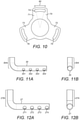
- FIG. 11A and FIG. 11B show, respectively, side and front end elevations of a first branch pipe and associated trunk portion pipe of the tree diffuser of FIGS. 6 to 9 ;
- FIG. 12A and FIG. 12B show respectively side and front end elevations of a second branch pipe and associated trunk portion pipe of the tree diffuser of FIGS. 6 to 9 ;
- FIG. 13A and FIG. 13B show respectively side and front end elevations of a third branch pipe and associated trunk portion pipe of the tree diffuser of FIGS. 6 to 9 ;
- FIGS. 14A to 14J are views of baffles used in the pig of FIGS. 2A and 2B .
- FIG. 1 there can be seen a pig 1000 .
- the pig 1000 may be used in a method of lining a water or sewage pipe as described in any of WO98/26919, WO2004/090411 or WO2004/090411; in some embodiments, the pig 1000 is designed to heat a liner sleeve of thermoplastic material and reinforcing elements.
- the pig 1000 can be used to heat a liner sleeve to form a rigid liner in any duct, for instance an electrical duct or a gas pipe as well as a water or sewage pipe.
- the pig 1000 is provided with a plurality of annular coiled heating elements 1001 to 1006 all arranged around a common axis 1007 .
- the pig 1000 has a gas inlet 1008 and heated gas leaves the pig 1000 in a radial direction via a series of apertures 1009 in an end ring 1020 of an outlet end 1010 of the pig 1000 .
- the inlet tube 1008 is radially offset from the axis 1007 , and gas delivered by the inlet tube 1008 passes through a first 90° bend 1011 and a second 90° bend 1012 , both formed in a passage provided in an end plate 1014 of the pig 1000 .
- the passage delivers the gas to a gas inlet 1015 via which gas is delivered to a cylindrical heating chamber 1017 of the pig 1000 , the heating chamber 1017 being the chamber in which the coiled heating elements 1001 - 1006 are located.
- the gas inlet 1015 lies on the axis 1007 .
- the cone 1018 in FIG. 1 illustrates expansion of gas in the heating chamber 1017 as it flows from an inlet end 1019 of the heating chamber to the outlet end 1010 of the heating chamber 1017 .
- the gas does not immediately flow to the inwardly facing cylindrical surface of the chamber 1017 and instead expands only gradually as it moves through the chamber 1017 , as illustrated by the cone 1018 .
- the pig 1000 cannot exceed a certain length (e.g. 700 mm) without the pig then becoming difficult to maneuver through a pipeline. Thus it is not possible to solve the problem of heating the gas effectively simply by extending the length of the cylindrical chamber 1017 and adding extra heating elements. Therefore there is a technical problem to be solved in improving the heating of the gas within a cylindrical chamber 1017 of a fixed length.
- the disclosure addresses this technical problem.
- FIG. 2A shows a cylindrical heating chamber 17 of a pig configured according to the disclosure, and does not show the remainder of the pig.
- the remainder of the pig will be similar to that shown in FIG. 1 .
- FIG. 2A shows Related reference numerals, e.g. the heating chamber is 17 in FIG. 2A and 1017 in FIG. 1 .
- FIG. 2A coiled heating elements 1 , 2 , 3 , 4 , 5 and 6 are shown, separated by baffles 19 , 20 , 21 , 22 and 23 , which will be described herein.
- the coiled heating elements 1 - 6 are arranged around a common axis 7 , which is a central axis of the cylindrical heating chamber 17 .
- the pig includes a tree diffuser 15 to deliver gas to the heating chamber 17 .
- the tree diffuser 15 comprises three sets of branch pipes: a set of branch pipes A, a set of branch pipes B and a set of branch pipes C.
- the branch pipes of the sets A, B and C all extend radially out from a central trunk 77 .
- Each branch pipe is connected with or formed integrally with its own trunk portion pipe of identical exterior and lumen diameters.
- the trunk portion pipes all extend adjacent to neighbouring trunk portion pipes to form the trunk 77 of the tree diffuser 15 , as will be described in relation to later figures.
- FIG. 2B shows an end face view of an inlet to the tree diffuser 15 .
- the set of branch pipes B comprises three branch pipes
- the set of branches A comprises also three branch pipes
- the set of branches C comprises six branch pipes.
- the trunk portion pipes associated with the branch pipes are shown in FIG. 2B , and they are shown all encased in a circular inlet pipe 78 .
- Each trunk portion pipe is circular in cross section, as can be seen in FIG. 2A , and each branch pipe will be of identical cross section to its associated trunk portion pipe; this is further described herein with reference to FIGS. 11A, 11B, 12A, 12B, 13A and 13B .
- the cross sectional areas of the lumens of the branch pipes and their associated trunk portion pipes are selected so that: the lumen of each branch pipe of set A carries 7.1% of the gas flow, with the lumens of three branch pipes of set A therefore carrying in total 21.3% of the gas flow; the lumen of each branch pipe of set B receives 10.3% of the air flow, with the lumens of the three branch pipes of set B together carrying 30.9% of the air flow; and the lumen of each branch pipe of set C receiving 4.98% of the gas flow, the six branch pipes of set C therefore carrying approximately 29.9% of the total gas flow.
- the remainder of the gas flow passes through the interstitial gaps defined between the trunk portion pipes of Sets A, B and C and the inlet pipe 78 which encases and surrounds them, such gaps being illustrated for instance as 24 , 25 and 26 in FIG. 2A .
- each branch pipe and associated trunk portion pipe of set A will have a lumen of a diameter of roughly 6.7 mm; each branch pipe and associated trunk portion pipe of set B will have a lumen of a diameter of roughly 8.04 mm; and each branch pipe and associated trunk portion pipe of set C will have a lumen of a diameter of roughly 5.58 mm.
- the inlet pipe 78 could be of a variety of diameters and then the diameters of the lumens of the pipes of sets A,B and C will vary also, the diameters being set in accordance with the ratios given in the previous paragraph.
- FIG. 3 shows branch pipes: 27 , 28 and 29 of set A; 30 , 31 and 32 of set B; and 34 , 35 , 36 , 37 , 38 , and 39 of set C.
- some branch pipes e.g. the branch pipes of set A
- other branch pipes e.g. the branch pipes of sets B and C
- the underlying branch pipes are shown in the view of FIG. 3 by making the overlying pipes “transparent” to some degree in the figure, although in practice all the pipes will be opaque metal pipes.
- Each pipe of set A has at least four apertures, for instance the apertures 40 , 41 , 42 and 43 of branch pipe 27 are shown in FIG. 3 .
- the arrows 44 , 45 , 46 , and 47 are shown to illustrate the flow of gas respectively from the apertures 40 , 41 , 42 and 43 .
- the other branch pipes 28 and 29 of set A have similar apertures and arrows are shown in the Figure to show the flow of gas from these apertures.
- the branch pipe 30 of the set of branch pipes B has apertures 48 , 49 , 50 , and 51 and the arrows 52 , 53 , 54 and 55 show the flow of gas respectively out of the apertures 48 , 49 , 50 and 51 .
- the other branch pipes 31 and 32 of the set B will have similar apertures, which for the sake of clarity are not referenced in the drawing, but arrows are given in FIG. 3 to show the direction of flow of gas from each of the apertures.
- the branch pipes of Set C shown as 34 - 39 in FIG. 3 , will each also have an end apertures provided in each of them to allow for the flow of gas out of them, as will be described later. However, for the sake of clarity in FIG. 3 these apertures are not shown, nor are arrows provided to illustrate the gas flow.
- FIG. 3 the arrows clearly show that the use of the tree diffuser 15 provides for the flow of gas across the transverse cross section area of the cylindrical chamber 17 .
- the branch pipes of Sets A, B and C extend between the coils of the coiled heating element 1 and the branch pipes of the Sets A and B extend out the majority of the distance to the inwardly facing surface of the cylindrical chamber 17 .
- the air introduced into the cylindrical chamber 17 by the tree diffuser 15 will flow over each of the coiled heating elements 1 to 6 and be heated thereby, significantly improving the heating efficiency of the pig.
- FIG. 4 shows a cover plate 70 which allows attachment of the tree diffuser to the end plate 14 of the pig.
- the cover plate 70 has three arms 71 , 72 and 73 , each of which is provided with a slot 74 , 75 , 76 .
- FIG. 5 it can be seen that the slots 74 , 75 and 76 align with threaded bores e.g. 79 , 80 in the end plate 14 of the pig.
- the cover plate 70 (and thereby the tree diffuser 15 ) will be secured in place by threaded bolts (not shown) screwed into the threaded bores (e.g. 79 , 80 ) in the end plate 14 .
- the slots 74 , 75 and 76 allow the cover plate to be secured in plate in a range of rotational orientations relative to the end plate 14 .
- a clearer view of the cover plate 70 is given in FIG. 10 , where the angle 90 is thirty degrees and this indicates that the slots 74 , 75 and 76 allow 30 degrees of rotation of the cover plate 70 relative to the adjacent end plate 14 .
- FIGS. 5, 6 and 7 it can be clearly seen the that the branch pipes 27 , 28 and 29 of set A extend over and overlay the underlying branch pipes 30 , 31 and 32 of the set B.
- FIG. 9 shows that this allows the angle 82 between the branch pipe 30 and the branch pipe 27 to be roughly 50 degrees (the angle 82 being the angle between the central axes of the branch pipes at their point of intersection when they are viewed as shown in FIG. 9 ).
- the angle 83 between the branch pipe 27 and the branch pipe 32 is roughly 70 degrees (the angle 83 being the angle between the central axes of the branch pipes at their point of intersection when they are viewed as shown in FIG. 9 ).
- the angle 84 between the branch pipe 32 and the branch pipe 29 is roughly 50 degrees (the angle 84 being the angle between the central axes of the branch pipes at their point of intersection when they are viewed as shown in FIG. 9 ).
- the angle 85 between the branch pipe 29 and the branch pipe 31 is roughly 70 degrees (the angle 85 being the angle between the central axes of the branch pipes at their point of intersection when they are viewed as shown in FIG. 9 ).
- the angle 86 between the branch pipe 31 and the branch pipe 28 is roughly 50 degrees (the angle 86 being the angle between the central axes of the branch pipes at their point of intersection when they are viewed as shown in FIG. 9 ).
- the angle 81 between the branch pipe 28 and the branch pipe 30 is roughly 70 degrees (the angle 81 being the angle between the central axes of the branch pipes at their point of intersection when they are viewed as shown in FIG. 9 ).
- the selected angles allow for a good distribution of gas flow around the heating chamber 17 as shown by the arrows in FIG. 3 .
- each of the branch pipes of the sets A and B has a closed end and a plurality of apertures spaced along its length formed in its cylindrical surface.
- FIGS. 13A and 13B Detailed views of branch pipe 34 of the set C are found in FIGS. 13A and 13B . It can been seen in FIG. 13A that the branch pipe 34 extends at right angles to a trunk portion pipe 34 A which is formed integrally therewith. It can be seen in FIG. 13B that the branch pipe 34 is provided with an outlet 90 at the open distal end of the branch pipe 34 .
- FIGS. 11A and 11B Detailed views of branch pipe 30 of the set B are found in FIGS. 11A and 11B .
- the branch pipe 30 extends at right angles to a trunk portion pipe 30 A which is formed integrally therewith.
- the trunk portion pipe 30 A of FIGS. 11A and 11B is significantly longer (preferably at least 50% longer) than the length of the trunk portion pipe 34 A of FIGS. 13A and 13B .
- the branch pipe 30 is significantly longer (preferably at least double in length) than the trunk portion pipe 30 A.
- the branch pipe 30 is provided with four apertures 301 , 302 , 303 and 304 in the cylindrical surface of the branch pipe 30 and spaced along its length, with the aperture 304 located close to the distal end of the branch pipe 30 .
- FIGS. 12A and 12B Detailed views of branch pipe 27 of the set A are found in FIGS. 12A and 12B .
- the branch pipe 27 extends at right angles to a trunk portion pipe 27 A which is formed integrally therewith.
- the trunk portion pipe 27 A of FIGS. 12A and 12B is significantly longer (preferably at least 50% longer) the length of the trunk portion pipe 30 A of FIGS. 11A and 11B .
- the branch pipe 27 is significantly longer (preferably at least double in length) than the trunk portion pipe 27 A.
- the branch pipe 27 is provided with four apertures 271 , 272 , 273 and 274 in the cylindrical surface of the branch pipe 27 and spaced along its length, with the aperture 274 located close to the distal end of the branch pipe 27 .
- baffles 19 to 23 The gas flow through the pig and the heating efficiency of the pig are further improved by the use of baffles 19 to 23 and a central core 56 on which the baffles 19 to 23 are mounted and which extends through apertures in the baffles 19 to 23 and through the central apertures of the coiled heating elements 2 to 6 (see FIG. 2A ).
- the central core 56 ensures that the gas flow through the cylindrical chamber 17 passes across the coiled heating elements 2 to 6 , rather than passing through their aligned central apertures.
- the baffles 19 to 23 are shown respectively in FIGS. 14 to 14E , all viewed face on from the inlet side of the heating chamber 17 .
- Each baffle has a central circular land and three arms extending radially out from the central circular land to a circular rim.
- the baffle 19 has a central circular land 57 and three arms 58 , 59 and 60 which connect the central land 57 to a circular exterior rim 61 .
- Each arm 58 , 59 and 60 is cruciform in shape, with a cross bar extending outwardly on both sides at a position approximately two thirds along the length of the arm, beginning at the land.
- the arm 58 has a cross bar 62
- the arm 59 has a cross bar 63
- the arm 60 has a cross bar 64 .
- the rim 61 is provided with notches 65 , 66 , 67 and 68 which are designed to engage detents provided on the inward facing surface of the cylindrical heating chamber 17 to hold the baffle 19 in place within the heating chamber 17 in a selected orientation.
- the baffles 20 , 21 , 22 and 23 have features identical to the baffle 19 , but the orientation of the arms of each baffle when secured in place within the cylindrical heating chamber 17 is different to the orientation of the arms of neighbouring baffles. For instance, looking at FIGS. 14A, 14B, and 14C it can be seen that the baffles 19 and 21 of FIGS. 14A and 14C have arms 58 and 58 ′ approximately at the 11 o'clock position, while the arm 58 ′′ of the baffle 20 in FIG. 14B is approximately at the 1 o'clock position.
- the arms 59 and 59 ′ of the baffles 19 and 21 are at the 3 o'clock position, whilst the arm 59 ′′ of the baffle 20 is at the 9 o'clock position. Furthermore the baffle arms 64 and 64 ′ of the baffles 19 and 21 are at the 7 o'clock position, whilst the arm 64 ′′ of the baffle 20 is at the 5 o'clock position.
- baffles The configuration of the baffles and their orientation with respect to each other are selected so that the flow of gas along the cylindrical chamber 17 is directed by the baffles across the coils of the coiled heating elements 1 - 6 .
- baffles 19 - 23 are all shown with a central land of a first diameter 57 of 53 mm
- alternative baffles 19 ′, 20 ′, 21 ′, 22 ′ and 23 ′ are shown in FIGS. 14F to 14J , with the baffles 19 ′, 20 ′, 21 ′, 22 ′ having a larger central land of a second diameter of 57 mm and the baffle 23 ′ having a much larger central land of a third diameter of 75 mm.
- baffles 19 ′, 20 ′, 21 ′, 22 ′ and 23 ′ could be used in place of the baffles 19 to 23 in certain situations in order to achieve a different arrangement of gas flow through the cylindrical heating chamber 17 .
- the baffle 23 ′ with the much larger central land could also be used with the baffles 19 - 22 , in place of the baffle 23 .
- the tree diffuser of the present invention improves the heating efficiency of the coiled heater elements by making sure the pressurized gas flows across the majority of the transverse cross section of the heating chamber 17 . Furthermore, the use of a plurality of different branch pipes achieves this effect without constraining the gas flow to such a degree that it becomes supersonic, which would be undesirable for the efficiency of the apparatus.
- the use of a plurality of branch pipes while also allowing also gas flow through the gaps between the trunk portion pipes and the surrounding heating chamber gas inlet pipe is important in preventing supersonic gas flow.
- the sets of branch pipes A and B described above could be swapped in position so that the slightly longer branch pipes A are sandwiched between the slightly shorter branch pipes B and the more numerous branch pipes C. This might make routing of the pipes easier in some situations.
Landscapes
- Engineering & Computer Science (AREA)
- General Engineering & Computer Science (AREA)
- Mechanical Engineering (AREA)
- Manufacturing & Machinery (AREA)
- Chemical & Material Sciences (AREA)
- Combustion & Propulsion (AREA)
- Physics & Mathematics (AREA)
- Thermal Sciences (AREA)
- Pipe Accessories (AREA)
- Lining Or Joining Of Plastics Or The Like (AREA)
Applications Claiming Priority (4)
| Application Number | Priority Date | Filing Date | Title |
|---|---|---|---|
| GB1616384 | 2016-09-27 | ||
| GB1616384.2 | 2016-09-27 | ||
| GB1616384.2A GB2554431B (en) | 2016-09-27 | 2016-09-27 | A pig for use in a system for lining ducts |
| PCT/GB2017/052887 WO2018060696A1 (en) | 2016-09-27 | 2017-09-27 | A pig for use in a system for lining ducts |
Publications (2)
| Publication Number | Publication Date |
|---|---|
| US20190234551A1 US20190234551A1 (en) | 2019-08-01 |
| US11280439B2 true US11280439B2 (en) | 2022-03-22 |
Family
ID=57539791
Family Applications (1)
| Application Number | Title | Priority Date | Filing Date |
|---|---|---|---|
| US16/336,458 Active 2038-12-06 US11280439B2 (en) | 2016-09-27 | 2017-09-27 | Pig for use in a system for lining ducts |
Country Status (7)
| Country | Link |
|---|---|
| US (1) | US11280439B2 (enExample) |
| EP (1) | EP3519723B1 (enExample) |
| JP (1) | JP6868701B2 (enExample) |
| AU (1) | AU2017335237B2 (enExample) |
| ES (1) | ES2843102T3 (enExample) |
| GB (1) | GB2554431B (enExample) |
| WO (1) | WO2018060696A1 (enExample) |
Families Citing this family (1)
| Publication number | Priority date | Publication date | Assignee | Title |
|---|---|---|---|---|
| GB2571127B (en) | 2018-02-19 | 2021-03-31 | Aqualiner Ltd | A pig for use in a system for lining ducts water or sewage pipes |
Citations (19)
| Publication number | Priority date | Publication date | Assignee | Title |
|---|---|---|---|---|
| US3643280A (en) | 1969-12-19 | 1972-02-22 | Marvin D Powers | Pipeline pigs |
| GB1366122A (en) | 1971-05-06 | 1974-09-11 | Gerber Garment Technology Inc | Method and apparatus for preparing bundles of sheet material |
| US4741795A (en) | 1985-08-15 | 1988-05-03 | Tate Pipe Lining Processes Limited | Method of and apparatus for lining pipes |
| US4781780A (en) | 1986-04-11 | 1988-11-01 | Du Pont (U.K.) Limited | Method of producing a thermoplastic polymer-lined pipe |
| JPH01154729A (ja) | 1987-12-11 | 1989-06-16 | Osaka Bosui Constr Co Ltd | 管内面の硬質チューブライニング工法 |
| DE3904524A1 (de) | 1989-02-15 | 1990-08-16 | Guenter Dr Ing Klemm | Verfahren zum auskleiden von rohrleitungen |
| US5309947A (en) | 1991-06-11 | 1994-05-10 | Werner & Pfleiderer, Gmbh | Apparatus for lining an inside wall of a sewer pipe |
| WO1996018493A1 (en) | 1994-12-17 | 1996-06-20 | John Wood | Re-forming thermoplastic members |
| WO1998026919A1 (en) | 1996-12-16 | 1998-06-25 | Severn Trent Water Limited | Thermoplastic composite products and method of lining pipework |
| JP2002086564A (ja) | 2000-09-20 | 2002-03-26 | Shonan Gosei Jushi Seisakusho:Kk | 管ライニング工法 |
| WO2002025156A2 (en) | 2000-09-19 | 2002-03-28 | Severn Trent Water Limited | Lining ducts |
| WO2004090411A1 (en) | 2003-04-12 | 2004-10-21 | Severn Trent Water Limited | Lining ducts |
| US20070275162A1 (en) * | 2006-05-23 | 2007-11-29 | Shonan Gosei-Jushi Seisakusho K.K. | Pipeline lining method |
| US7827646B2 (en) | 2008-02-08 | 2010-11-09 | Tdw Delaware, Inc. | Vortex inhibitor dispersal pig |
| US8281444B2 (en) | 2006-01-20 | 2012-10-09 | Rosen Swiss Ag | Cleaning pig |
| US20150265980A1 (en) * | 2012-10-19 | 2015-09-24 | Mitsubishi Rayon Co., Ltd. | Air diffusion device, air diffusion method, and water treatment device |
| US20170299106A1 (en) | 2016-04-19 | 2017-10-19 | Peanta Inventions AB c/o Deductio AB | Light head for use in relining pipes |
| EP3336404A1 (en) | 2016-12-14 | 2018-06-20 | Bolonia Servicios e Ingenieros, S.L. | A device for curing pipeline inner resin linings |
| GB2571127A (en) | 2018-02-19 | 2019-08-21 | Aqualiner Ltd | A pig for use in a system for lining ducts water or sewage pipes |
Family Cites Families (3)
| Publication number | Priority date | Publication date | Assignee | Title |
|---|---|---|---|---|
| JPH02194927A (ja) * | 1989-01-24 | 1990-08-01 | Sumitomo Metal Ind Ltd | 既設管の内面ライニング補修工法 |
| JPH0880566A (ja) * | 1994-09-12 | 1996-03-26 | Maruzen Polymer Kk | 埋設パイプ内面のライニング工法 |
| JP4916784B2 (ja) * | 2006-06-20 | 2012-04-18 | 吉佳株式会社 | 光硬化性ライニング材の光硬化方法及び該方法に用いる光硬化システム |
-
2016
- 2016-09-27 GB GB1616384.2A patent/GB2554431B/en not_active Expired - Fee Related
-
2017
- 2017-09-27 JP JP2019537898A patent/JP6868701B2/ja active Active
- 2017-09-27 EP EP17780151.1A patent/EP3519723B1/en active Active
- 2017-09-27 WO PCT/GB2017/052887 patent/WO2018060696A1/en not_active Ceased
- 2017-09-27 AU AU2017335237A patent/AU2017335237B2/en active Active
- 2017-09-27 ES ES17780151T patent/ES2843102T3/es active Active
- 2017-09-27 US US16/336,458 patent/US11280439B2/en active Active
Patent Citations (23)
| Publication number | Priority date | Publication date | Assignee | Title |
|---|---|---|---|---|
| US3643280A (en) | 1969-12-19 | 1972-02-22 | Marvin D Powers | Pipeline pigs |
| GB1366122A (en) | 1971-05-06 | 1974-09-11 | Gerber Garment Technology Inc | Method and apparatus for preparing bundles of sheet material |
| US4741795A (en) | 1985-08-15 | 1988-05-03 | Tate Pipe Lining Processes Limited | Method of and apparatus for lining pipes |
| US4781780A (en) | 1986-04-11 | 1988-11-01 | Du Pont (U.K.) Limited | Method of producing a thermoplastic polymer-lined pipe |
| EP0369998A2 (en) | 1986-04-11 | 1990-05-23 | Du Pont (UK) Limited | Radiant heater |
| JPH01154729A (ja) | 1987-12-11 | 1989-06-16 | Osaka Bosui Constr Co Ltd | 管内面の硬質チューブライニング工法 |
| DE3904524A1 (de) | 1989-02-15 | 1990-08-16 | Guenter Dr Ing Klemm | Verfahren zum auskleiden von rohrleitungen |
| US5309947A (en) | 1991-06-11 | 1994-05-10 | Werner & Pfleiderer, Gmbh | Apparatus for lining an inside wall of a sewer pipe |
| WO1996018493A1 (en) | 1994-12-17 | 1996-06-20 | John Wood | Re-forming thermoplastic members |
| US6228312B1 (en) | 1996-12-16 | 2001-05-08 | Severn Trent Water Limited | Thermoplastic composite products and method of lining pipework |
| WO1998026919A1 (en) | 1996-12-16 | 1998-06-25 | Severn Trent Water Limited | Thermoplastic composite products and method of lining pipework |
| WO2002025156A2 (en) | 2000-09-19 | 2002-03-28 | Severn Trent Water Limited | Lining ducts |
| US20040036202A1 (en) | 2000-09-19 | 2004-02-26 | Weatherby Nicholas Leo | Lining ducts |
| JP2002086564A (ja) | 2000-09-20 | 2002-03-26 | Shonan Gosei Jushi Seisakusho:Kk | 管ライニング工法 |
| WO2004090411A1 (en) | 2003-04-12 | 2004-10-21 | Severn Trent Water Limited | Lining ducts |
| US8281444B2 (en) | 2006-01-20 | 2012-10-09 | Rosen Swiss Ag | Cleaning pig |
| US20070275162A1 (en) * | 2006-05-23 | 2007-11-29 | Shonan Gosei-Jushi Seisakusho K.K. | Pipeline lining method |
| US7827646B2 (en) | 2008-02-08 | 2010-11-09 | Tdw Delaware, Inc. | Vortex inhibitor dispersal pig |
| US20150265980A1 (en) * | 2012-10-19 | 2015-09-24 | Mitsubishi Rayon Co., Ltd. | Air diffusion device, air diffusion method, and water treatment device |
| US20170299106A1 (en) | 2016-04-19 | 2017-10-19 | Peanta Inventions AB c/o Deductio AB | Light head for use in relining pipes |
| EP3336404A1 (en) | 2016-12-14 | 2018-06-20 | Bolonia Servicios e Ingenieros, S.L. | A device for curing pipeline inner resin linings |
| GB2571127A (en) | 2018-02-19 | 2019-08-21 | Aqualiner Ltd | A pig for use in a system for lining ducts water or sewage pipes |
| WO2019158950A1 (en) | 2018-02-19 | 2019-08-22 | Aqualiner Limited | A pig for use in a system for lining ducts water or sewage pipes |
Also Published As
| Publication number | Publication date |
|---|---|
| JP6868701B2 (ja) | 2021-05-12 |
| EP3519723B1 (en) | 2021-01-06 |
| WO2018060696A1 (en) | 2018-04-05 |
| ES2843102T3 (es) | 2021-07-15 |
| AU2017335237A1 (en) | 2019-04-18 |
| US20190234551A1 (en) | 2019-08-01 |
| GB201616384D0 (en) | 2016-11-09 |
| GB2554431A (en) | 2018-04-04 |
| JP2019529197A (ja) | 2019-10-17 |
| EP3519723A1 (en) | 2019-08-07 |
| AU2017335237B2 (en) | 2023-01-12 |
| GB2554431B (en) | 2018-08-22 |
Similar Documents
| Publication | Publication Date | Title |
|---|---|---|
| US11280439B2 (en) | Pig for use in a system for lining ducts | |
| US11613083B2 (en) | Pig for use in a system for lining ducts water or sewage pipes | |
| RU2019125249A (ru) | Композитные соединители и способы их изготовления | |
| JP6560645B2 (ja) | 配管継手を用いた配管システム | |
| US10465942B2 (en) | Integrated water heater | |
| KR102143793B1 (ko) | 나선형 날개를 갖는 열교환장치 | |
| US5448040A (en) | Roller for furnaces, particularly for iron and steel making furnaces for heating slabs or the like | |
| JP5996238B2 (ja) | 配管継手及びこれを用いた配管システム | |
| JP2019529197A5 (enExample) | ||
| JP7033954B2 (ja) | 管穴あけ用取り付け具 | |
| US11796215B2 (en) | Device for distributing air | |
| JP2551036B2 (ja) | 合成樹脂管の曲げ加工法 | |
| KR20230099795A (ko) | 동결 주조를 통해 관 벽에 에어로젤 구조물을 형성하는 장치 | |
| CN217685997U (zh) | 进出液组件、空调器 | |
| JP3699333B2 (ja) | 既設管路の補修工法 | |
| KR20240046535A (ko) | 공압식 재료 이송 시스템의 이송 파이프 배열체, 이송 파이프 배열체를 형성하기 위한 방법, 및 연결 피스 | |
| JP2003047118A (ja) | 光通信ケーブル用埋設管 | |
| KR20110017701A (ko) | 와이 분지관 및 이의 연결구조 | |
| JP2005042861A (ja) | 2重管継ぎ手およびそれに用いるアウターチューブ | |
| CN109662588A (zh) | 饮水机 |
Legal Events
| Date | Code | Title | Description |
|---|---|---|---|
| AS | Assignment |
Owner name: AQUALINER LIMITED, UNITED KINGDOM Free format text: ASSIGNMENT OF ASSIGNORS INTEREST;ASSIGNOR:ELSOM, ROBIN;REEL/FRAME:048693/0434 Effective date: 20190315 |
|
| FEPP | Fee payment procedure |
Free format text: ENTITY STATUS SET TO UNDISCOUNTED (ORIGINAL EVENT CODE: BIG.); ENTITY STATUS OF PATENT OWNER: LARGE ENTITY |
|
| STPP | Information on status: patent application and granting procedure in general |
Free format text: APPLICATION UNDERGOING PREEXAM PROCESSING |
|
| FEPP | Fee payment procedure |
Free format text: ENTITY STATUS SET TO SMALL (ORIGINAL EVENT CODE: SMAL); ENTITY STATUS OF PATENT OWNER: LARGE ENTITY |
|
| STPP | Information on status: patent application and granting procedure in general |
Free format text: APPLICATION DISPATCHED FROM PREEXAM, NOT YET DOCKETED |
|
| STPP | Information on status: patent application and granting procedure in general |
Free format text: DOCKETED NEW CASE - READY FOR EXAMINATION |
|
| FEPP | Fee payment procedure |
Free format text: ENTITY STATUS SET TO UNDISCOUNTED (ORIGINAL EVENT CODE: BIG.); ENTITY STATUS OF PATENT OWNER: LARGE ENTITY |
|
| STPP | Information on status: patent application and granting procedure in general |
Free format text: NOTICE OF ALLOWANCE MAILED -- APPLICATION RECEIVED IN OFFICE OF PUBLICATIONS |
|
| STPP | Information on status: patent application and granting procedure in general |
Free format text: PUBLICATIONS -- ISSUE FEE PAYMENT VERIFIED |
|
| FEPP | Fee payment procedure |
Free format text: PETITION RELATED TO MAINTENANCE FEES GRANTED (ORIGINAL EVENT CODE: PTGR); ENTITY STATUS OF PATENT OWNER: LARGE ENTITY |
|
| STCF | Information on status: patent grant |
Free format text: PATENTED CASE |
|
| FEPP | Fee payment procedure |
Free format text: PETITION RELATED TO MAINTENANCE FEES GRANTED (ORIGINAL EVENT CODE: PTGR); ENTITY STATUS OF PATENT OWNER: LARGE ENTITY |
|
| MAFP | Maintenance fee payment |
Free format text: PAYMENT OF MAINTENANCE FEE, 4TH YEAR, LARGE ENTITY (ORIGINAL EVENT CODE: M1551); ENTITY STATUS OF PATENT OWNER: LARGE ENTITY Year of fee payment: 4 |