US11271211B2 - Anode current collector, conductive material, and fluoride ion battery - Google Patents
Anode current collector, conductive material, and fluoride ion battery Download PDFInfo
- Publication number
- US11271211B2 US11271211B2 US15/252,693 US201615252693A US11271211B2 US 11271211 B2 US11271211 B2 US 11271211B2 US 201615252693 A US201615252693 A US 201615252693A US 11271211 B2 US11271211 B2 US 11271211B2
- Authority
- US
- United States
- Prior art keywords
- active material
- current collector
- ion battery
- fluoride
- anode
- Prior art date
- Legal status (The legal status is an assumption and is not a legal conclusion. Google has not performed a legal analysis and makes no representation as to the accuracy of the status listed.)
- Active, expires
Links
Images


Classifications
-
- H—ELECTRICITY
- H01—ELECTRIC ELEMENTS
- H01M—PROCESSES OR MEANS, e.g. BATTERIES, FOR THE DIRECT CONVERSION OF CHEMICAL ENERGY INTO ELECTRICAL ENERGY
- H01M4/00—Electrodes
- H01M4/02—Electrodes composed of, or comprising, active material
- H01M4/64—Carriers or collectors
- H01M4/66—Selection of materials
- H01M4/661—Metal or alloys, e.g. alloy coatings
-
- H—ELECTRICITY
- H01—ELECTRIC ELEMENTS
- H01M—PROCESSES OR MEANS, e.g. BATTERIES, FOR THE DIRECT CONVERSION OF CHEMICAL ENERGY INTO ELECTRICAL ENERGY
- H01M10/00—Secondary cells; Manufacture thereof
- H01M10/05—Accumulators with non-aqueous electrolyte
-
- H—ELECTRICITY
- H01—ELECTRIC ELEMENTS
- H01M—PROCESSES OR MEANS, e.g. BATTERIES, FOR THE DIRECT CONVERSION OF CHEMICAL ENERGY INTO ELECTRICAL ENERGY
- H01M10/00—Secondary cells; Manufacture thereof
- H01M10/05—Accumulators with non-aqueous electrolyte
- H01M10/056—Accumulators with non-aqueous electrolyte characterised by the materials used as electrolytes, e.g. mixed inorganic/organic electrolytes
- H01M10/0564—Accumulators with non-aqueous electrolyte characterised by the materials used as electrolytes, e.g. mixed inorganic/organic electrolytes the electrolyte being constituted of organic materials only
- H01M10/0566—Liquid materials
- H01M10/0568—Liquid materials characterised by the solutes
-
- H—ELECTRICITY
- H01—ELECTRIC ELEMENTS
- H01M—PROCESSES OR MEANS, e.g. BATTERIES, FOR THE DIRECT CONVERSION OF CHEMICAL ENERGY INTO ELECTRICAL ENERGY
- H01M10/00—Secondary cells; Manufacture thereof
- H01M10/05—Accumulators with non-aqueous electrolyte
- H01M10/056—Accumulators with non-aqueous electrolyte characterised by the materials used as electrolytes, e.g. mixed inorganic/organic electrolytes
- H01M10/0564—Accumulators with non-aqueous electrolyte characterised by the materials used as electrolytes, e.g. mixed inorganic/organic electrolytes the electrolyte being constituted of organic materials only
- H01M10/0566—Liquid materials
- H01M10/0569—Liquid materials characterised by the solvents
-
- H—ELECTRICITY
- H01—ELECTRIC ELEMENTS
- H01M—PROCESSES OR MEANS, e.g. BATTERIES, FOR THE DIRECT CONVERSION OF CHEMICAL ENERGY INTO ELECTRICAL ENERGY
- H01M4/00—Electrodes
- H01M4/02—Electrodes composed of, or comprising, active material
- H01M4/36—Selection of substances as active materials, active masses, active liquids
- H01M4/38—Selection of substances as active materials, active masses, active liquids of elements or alloys
- H01M4/381—Alkaline or alkaline earth metals elements
-
- H—ELECTRICITY
- H01—ELECTRIC ELEMENTS
- H01M—PROCESSES OR MEANS, e.g. BATTERIES, FOR THE DIRECT CONVERSION OF CHEMICAL ENERGY INTO ELECTRICAL ENERGY
- H01M4/00—Electrodes
- H01M4/02—Electrodes composed of, or comprising, active material
- H01M4/36—Selection of substances as active materials, active masses, active liquids
- H01M4/58—Selection of substances as active materials, active masses, active liquids of inorganic compounds other than oxides or hydroxides, e.g. sulfides, selenides, tellurides, halogenides or LiCoFy; of polyanionic structures, e.g. phosphates, silicates or borates
-
- H—ELECTRICITY
- H01—ELECTRIC ELEMENTS
- H01M—PROCESSES OR MEANS, e.g. BATTERIES, FOR THE DIRECT CONVERSION OF CHEMICAL ENERGY INTO ELECTRICAL ENERGY
- H01M4/00—Electrodes
- H01M4/02—Electrodes composed of, or comprising, active material
- H01M4/62—Selection of inactive substances as ingredients for active masses, e.g. binders, fillers
- H01M4/624—Electric conductive fillers
- H01M4/626—Metals
-
- H—ELECTRICITY
- H01—ELECTRIC ELEMENTS
- H01M—PROCESSES OR MEANS, e.g. BATTERIES, FOR THE DIRECT CONVERSION OF CHEMICAL ENERGY INTO ELECTRICAL ENERGY
- H01M4/00—Electrodes
- H01M4/02—Electrodes composed of, or comprising, active material
- H01M4/62—Selection of inactive substances as ingredients for active masses, e.g. binders, fillers
- H01M4/628—Inhibitors, e.g. gassing inhibitors, corrosion inhibitors
-
- H—ELECTRICITY
- H01—ELECTRIC ELEMENTS
- H01M—PROCESSES OR MEANS, e.g. BATTERIES, FOR THE DIRECT CONVERSION OF CHEMICAL ENERGY INTO ELECTRICAL ENERGY
- H01M4/00—Electrodes
- H01M4/02—Electrodes composed of, or comprising, active material
- H01M4/64—Carriers or collectors
- H01M4/66—Selection of materials
- H01M4/661—Metal or alloys, e.g. alloy coatings
- H01M4/662—Alloys
-
- H—ELECTRICITY
- H01—ELECTRIC ELEMENTS
- H01M—PROCESSES OR MEANS, e.g. BATTERIES, FOR THE DIRECT CONVERSION OF CHEMICAL ENERGY INTO ELECTRICAL ENERGY
- H01M4/00—Electrodes
- H01M4/02—Electrodes composed of, or comprising, active material
- H01M4/64—Carriers or collectors
- H01M4/66—Selection of materials
- H01M4/669—Steels
-
- H—ELECTRICITY
- H01—ELECTRIC ELEMENTS
- H01M—PROCESSES OR MEANS, e.g. BATTERIES, FOR THE DIRECT CONVERSION OF CHEMICAL ENERGY INTO ELECTRICAL ENERGY
- H01M10/00—Secondary cells; Manufacture thereof
- H01M10/05—Accumulators with non-aqueous electrolyte
- H01M10/052—Li-accumulators
-
- H—ELECTRICITY
- H01—ELECTRIC ELEMENTS
- H01M—PROCESSES OR MEANS, e.g. BATTERIES, FOR THE DIRECT CONVERSION OF CHEMICAL ENERGY INTO ELECTRICAL ENERGY
- H01M2300/00—Electrolytes
- H01M2300/0017—Non-aqueous electrolytes
- H01M2300/0025—Organic electrolyte
-
- H—ELECTRICITY
- H01—ELECTRIC ELEMENTS
- H01M—PROCESSES OR MEANS, e.g. BATTERIES, FOR THE DIRECT CONVERSION OF CHEMICAL ENERGY INTO ELECTRICAL ENERGY
- H01M2300/00—Electrolytes
- H01M2300/0017—Non-aqueous electrolytes
- H01M2300/0025—Organic electrolyte
- H01M2300/0028—Organic electrolyte characterised by the solvent
-
- H—ELECTRICITY
- H01—ELECTRIC ELEMENTS
- H01M—PROCESSES OR MEANS, e.g. BATTERIES, FOR THE DIRECT CONVERSION OF CHEMICAL ENERGY INTO ELECTRICAL ENERGY
- H01M4/00—Electrodes
- H01M4/02—Electrodes composed of, or comprising, active material
- H01M4/36—Selection of substances as active materials, active masses, active liquids
- H01M4/58—Selection of substances as active materials, active masses, active liquids of inorganic compounds other than oxides or hydroxides, e.g. sulfides, selenides, tellurides, halogenides or LiCoFy; of polyanionic structures, e.g. phosphates, silicates or borates
- H01M4/583—Carbonaceous material, e.g. graphite-intercalation compounds or CFx
- H01M4/5835—Comprising fluorine or fluoride salts
-
- Y—GENERAL TAGGING OF NEW TECHNOLOGICAL DEVELOPMENTS; GENERAL TAGGING OF CROSS-SECTIONAL TECHNOLOGIES SPANNING OVER SEVERAL SECTIONS OF THE IPC; TECHNICAL SUBJECTS COVERED BY FORMER USPC CROSS-REFERENCE ART COLLECTIONS [XRACs] AND DIGESTS
- Y02—TECHNOLOGIES OR APPLICATIONS FOR MITIGATION OR ADAPTATION AGAINST CLIMATE CHANGE
- Y02E—REDUCTION OF GREENHOUSE GAS [GHG] EMISSIONS, RELATED TO ENERGY GENERATION, TRANSMISSION OR DISTRIBUTION
- Y02E60/00—Enabling technologies; Technologies with a potential or indirect contribution to GHG emissions mitigation
- Y02E60/10—Energy storage using batteries
Definitions
- the present invention relates to an anode current collector that can inhibit the reaction with liquid electrolyte.
- a Li ion battery is known as a high-voltage and high-energy density battery.
- the Li ion battery is a cation-based battery utilizing a reaction between a Li ion and a cathode active material and a reaction between a Li ion and an anode active material.
- a fluoride ion battery utilizing a reaction of a fluoride ion is known.
- Patent Literature 1 discloses a Li ion battery including a carbonic cathode, LiF salt, and a non-aqueous electrolyte solution containing an anion receptor that connects to a fluoride ion. Further, it is described that this battery may be a dual intercalation electrode Li ion battery, and it is described that each electrode reversibly intercalate the ion supplied by LiF salt. Also, with regard to examples of the materials for a current collector, copper, silver, gold, platinum, nickel, cobalt, palladium, aluminum, or those alloy are disclosed.
- Patent Literature 2 disclosed a fluoride ion battery comprising an anode, a cathode, an electrolyte including a fluoride salt that is at least partially dissolved in a solvent, and an additive including a fluoride composite producing seed.
- specific example of the current collector is not described in Patent Literature 2.
- Patent Literature 1 Japanese Patent Application Laid-Open (JP-A) No. 2008-543002
- Patent Literature 2 JP-A No. 2014-501434
- Patent Literature 1 it is disclosed that Cu is used for an anode current collector.
- usage of Cu for an anode current collector in a fluoride ion battery arise a new problem that the reaction with a liquid electrolyte is caused at relatively high potential.
- the present invention was made in a nod to the circumstances and a main object thereof is to provide an anode current collector that is capable of inhibiting the reaction with a liquid electrolyte.
- the inventors have been researched as hard as possible and found out that the potential, at which the reaction with the liquid electrolyte occurs, increases in accordance with kinds of a metal to be used for an anode current collector. Above all, it was found out that the potential, at which the reaction with the liquid electrolyte occurs, significantly decreases when a specific metal is used for an anode current collector, and the present invention was achieved consequently.
- the present invention provides an anode current collector to be used for a fluoride ion battery, and the anode current collector is a simple substance of Fe, Mg, or Ti, or an alloy containing one or more of these metal elements.
- usage of the specific metal allows an anode current collector to be capable of inhibiting the reaction with the liquid electrolyte.
- the anode current collector is preferably a simple substance of Fe, or an alloy containing Fe.
- the alloy containing Fe is preferably a stainless steel.
- the present invention provides a conductive material to be used for a fluoride ion battery, the conductive material comprising a simple substance of Fe, Mg, or Ti, or an alloy containing one or more of these metal elements.
- usage of the specific metal allows a conductive material to be capable of inhibiting the reaction with the liquid electrolyte.
- the present invention provides a fluoride ion battery comprising a cathode active material layer containing a cathode active material, an anode active material layer containing an anode active material, an electrolyte layer formed between the cathode active material layer and the anode active material layer, a cathode current collector for collecting currents of the cathode active material layer, and an anode current collector for collecting currents of the anode active material layer, wherein the anode current collector is the anode current collector described above.
- usage of the above described anode current collector allows a fluoride ion battery to be capable of inhibiting reaction with the liquid electrolyte. Accordingly, improvement of the coulomb efficiency may be achieved, for example.
- the present invention may provide a fluoride ion battery comprising a cathode active material layer containing a cathode active material, an anode active material layer containing an anode active material, an electrolyte layer formed between the cathode active material layer and the anode active material layer, a cathode current collector for collecting currents of the cathode active material layer and an anode current collector for collecting currents of the anode active material layer, wherein at least one of the cathode active material layer and the anode active material layer contains the conductive material described above.
- usage of the above-described conductive material allows a fluoride ion battery to be capable of inhibiting reaction with the liquid electrolyte. Accordingly, improvement of the coulomb efficiency may be achieved, for example.
- An anode current collector of the present invention exhibits an effect that can inhibit the reaction with the liquid electrolyte.
- FIG. 1 is a schematic cross-sectional view showing an example of a fluoride ion battery of the present invention.
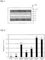
- FIG. 2 is the results of CP measurement for the measurement samples in Examples 1, 2 and Comparative Examples 1 to 5.
- FIG. 3 is the results of CP measurement for the measurement samples in Examples 3 to 5 and Comparative Examples 6 and 7.
- FIG. 4 is the results of CP measurement for the measurement samples in Examples 6 to 8.
- An anode current collector, a conductive material, and a fluoride ion battery of the present invention are hereinafter described in detail.
- An anode current collector of the present invention is the anode current collector to be used for a fluoride ion battery, and the anode current collector is a simple substance of Fe, Mg, or Ti, or an alloy containing one or more of these metal elements.
- the liquid electrolyte to be used for a fluoride ion battery usually has fluoride anion conductivity.
- fluoride anion conductivity refers to the ion conductivity in regard to fluoride ions in a broad sense. In terms of fluoride ions, an ion is not conducted well independently and is conducted as a fluoride anion (such as a fluoride complex anion) in some cases. Accordingly, the term fluoride anion conductivity is used in the present invention.
- a fluoride is an element with the highest electric negativity among all elements, and the fluoride anion that is the anion of such fluoride has significantly high reactivity.
- each element of Fe, Mg, and Ti is stable to the fluoride anion contained in the liquid electrolyte under reduction atmosphere so that the reaction with the liquid electrolyte may be inhibited.
- Cu is used as a typical anode current collector.
- the reaction with the liquid electrolyte occurs at high potential which is about 1 V vs. Li/Li + .
- the reaction of the anode current collector and the liquid electrolyte is not the objected reaction (fluoridation and defluoridation of the anode active material), but is the side reaction. It is presumed that the occurrence of the side reaction leads to decrease in coulomb efficiency of a battery and to malfunctioning as a battery.
- the anode current collector of the present invention is stable to the liquid electrolyte until the potential becomes 0.2 V vs. Li/Li + or less, for example. Accordingly, the anode current collector of the present invention is easily used with an anode active material with low reaction potential. Usage of an anode active material with low reaction potential allows comparatively large potential difference between a cathode active material and an anode active material, and thus a fluoride ion battery with high voltage may be obtained. Also, undesirable outcomes such as decrease in coulomb efficiency of a battery may be restrained.
- an anode active material containing a Ce element, an Mg element or a Ca element is an anode active material with high capacity.
- the theoretical potential of sCe/CeF 3 reaction is 0.45 V vs. Li/Li +
- the theoretical potential of Mg/MgF 2 reaction is 0.28 V vs. Li/Li ⁇
- the theoretical potential of Ca/CaF 2 reaction is ⁇ 0.23 V vs. Li/Li + .
- a fluoride ion with high capacity may be obtained by using these anode active materials along with the anode current collector of the present invention.
- the theoretical potential of Li/LiF reaction is ⁇ 0.27 V vs.
- the anode current collector is preferably stable to the liquid electrolyte until the potential becomes 0.4 V vs. Li/Li + or less for example, and is more preferably stable to the liquid electrolyte until the potential becomes 0.2 V vs. Li/Li + or less.
- the anode current collector that is a simple substance of Fe, Mg, or Ti, or an alloy containing one or more of these metal elements, is possibly a material known in the fields such as the field of lithium ion batteries.
- a fluoride anion has significantly high reactivity. In the field of fluoride ion batteries, whether a liquid electrolyte reacts with an anode current collector, and about what potential the liquid electrolyte reacts with the anode current collector at are not known.
- the potential, at which the reaction with the liquid electrolyte occurs greatly differs in accordance with the kind of a metal to be used for an anode current collector, and found out that the potential, at which the reaction with the liquid electrolyte occurs, is significantly decreased when the specific metal is used as the anode current collector.
- the anode current collector in the present invention is usually a simple substance of Fe, Mg, or Ti, or an alloy containing one or more of these metal elements.
- the alloy is an alloy containing an Me element (Me is at least one of Fe, Mg, and Ti).
- An Me element may be one kind, may be two kinds, and may be three kinds.
- the alloy may be an alloy constituted with just an Me element, and may be an alloy further containing one kind or two or more kinds of other elements.
- Examples of the other elements may include a C element, a Si element, a Mn element, a P element, a S element, a Ni element, a Cr element, a Mo element, a Cu element, a N element, an Al element, a Zn element, a Li element, a Ca element, a Sn element, and a V element.
- the alloy may include an alloy containing an Fe element, an alloy containing a Mg element, an alloy containing a Ti element, an alloy containing an Fe element and a Mg element, an alloy containing an Fe element and a Ti element, an alloy containing a Mg element and a Ti element, an alloy containing an Fe element, a Mg element and a Ti element.
- these alloys may be an alloy constituted with just an Me element and may be an alloy further containing other elements.
- Examples of the alloy containing an Fe element may include stainless steel.
- Examples of the alloy containing a Mg element may include a calcium magnesium alloy, and an aluminum magnesium alloy (a lithium aluminum magnesium alloy, an aluminum zinc magnesium alloy).
- Examples of the alloy containing a Ti element may include an aluminum titanium alloy (an aluminum vanadium titanium alloy, an aluminum chromium titanium alloy, and an aluminum tin titanium alloy).
- the ratio of an Me element in the whole anode current collector may be 1% by weight or more for example, may be 5% by weight or more, and may be 10% by weight or more.
- the ratio of an Me element in the whole anode current collector is 100% by weight at the maximum.
- the anode current collector in the present invention may contain an Me element as the main component.
- the ratio of an Me element in the whole alloy is 50% by weight or more for example, may be 70% by weight or more, and may be 90% by weight or more.
- the anode current collector in the present invention may contain other element than an Me element as the main component. In this case, the ratio of the other element in the whole alloy is 50% by weight or more for example, may be 70% by weight or more, and may be 90% by weight or more.
- the shape of the anode current collector may include a foil shape, a mesh shape, a porous shape, and a sponge shape.
- the thickness of the anode current collector is not particularly limited, but is preferably thin in the view point of the battery capacity improvement.
- the anode current collector may be disposed in arbitrary place to collect currents of the anode active material layer.
- the anode current collector is usually used for a fluoride ion battery.
- the conductive material of the present invention is a conductive material to be used for a fluoride ion battery, and comprises a simple substance of Fe, Mg, or Ti, or an alloy containing one or more of these metal elements.
- the conductive material may be capable of inhibiting the reaction with the liquid electrolyte.
- the contents of the conductive material of the present invention are basically the same as described in “A. Anode current collector”, thus the description herein is omitted.
- examples of the shape of the conductive material may include a foil shape, a mesh shape, a porous shape, and a sponge shape.
- an electrode may be obtained by preparing the electrode mixture containing at least the conductive material and active material, and then coating the current collector with the electrode mixture.
- the conductive material may also function as the current collector.
- FIG. 1 is a schematic cross-sectional view illustrating an example of a fluoride ion battery of the present invention.
- the fluoride ion battery 10 shown in FIG. 1 has a cathode active material layer 1 containing a cathode active material, an anode active material layer 2 containing an anode active material, an electrolyte layer 3 formed between the cathode active material layer 1 and the anode active material layer 2 , a cathode current collector 4 for collecting currents of the cathode active material layer 1 , an anode current collector 5 for collecting currents of the anode active material layer 2 , and a battery case 6 for storing these members.
- the present invention features the configuration in which the above described anode current collector is used as the anode current collector 5 .
- the present invention features the configuration in which at least one of the cathode active material layer 1 and the anode active material layer 2 contains the conductive material described above.
- usage of the above described anode current collector or conductive material allows a fluoride ion battery in which the reaction with the liquid electrolyte is inhibited. Accordingly, for example, improvement of the coulomb efficiency may be achieved.
- the fluoride ion battery of the present invention is hereinafter described in each constitution.
- the fluoride ion battery of the present invention has an anode active material layer, and an anode current collector for collecting currents of the anode active material layer.
- the anode active material layer is a layer containing at least an anode active material.
- the anode active material layer may further contain at least one of a conductive material and a binder other than the anode active material.
- the anode active material in the present invention is usually an active material that is fluorinated at the time of discharging.
- arbitrary active material that has lower potential than that of the cathode active material may be selected for the anode active material. Accordingly, the later described cathode active material may be used as the anode active material.
- the anode active materials may include a simple substance of metal, an alloy, a metal oxide, and fluorides of these.
- the metal elements contained in the anode active material may include La, Ca, Al, Eu, Li, Si, Ge, Sn, In, V, Cd, Cr, Fe, Zn, Ga, Ti, Nb, Mn, Yb, Zr, Sm, Ce, Mg, and Pb.
- the anode active material is preferably La, LaF x , Co, CoF x , Mg, MgF x , Ca, CaF x , Al, and AlF x .
- the “x” is a real number that is larger than 0.
- the theoretical potential (V vs. Li/Li ⁇ ) of M/MF x reaction in the anode active material (M) is 1 V or less for example, may be 0.5 V or less, and may be 0.3 V or less.
- the fluoride ion battery with high voltage may be obtained by using the anode active material with low potential.
- the theoretical potential (V vs. Li/Li + ) of M/MF x reaction in the anode active material (M) is ⁇ 1.0 V or more for example.
- the theoretical potential of M/MF x reaction in the anode active material (M) is preferably higher than the potential at which the anode current collector reacts with the liquid electrolyte.
- the conductive material is not particularly limited if the material has the desired electric conductivity, but examples thereof may include carbon materials and metal materials.
- the carbon materials may include carbon blacks such as acetylene black, Ketjen black, furnace black, and thermal black; graphene, fullerene, and carbon nanotube.
- the metal materials may include the same materials for above described anode current collector.
- the conductive material described in “B. Conductive material” above is preferably used.
- the anode active material layer contains the conductive material described in “B. Conductive material” above, the anode active material layer may or may not contain a carbon material as the conductive material.
- the binder is not particularly limited if it is chemically and electrically stable, but examples thereof may include fluoride-based binders such as polyvinylidene fluoride (PVDF), and polytetrafluoroethylene (PTFE), hydrocarbon-based binders such as polyimide, and silicon-based binders.
- fluoride-based binders such as polyvinylidene fluoride (PVDF), and polytetrafluoroethylene (PTFE)
- hydrocarbon-based binders such as polyimide
- silicon-based binders such as polyimide, and silicon-based binders.
- the content of the anode active material in the anode active material layer is preferably larger in the view point of the capacity; the content is 30% by weight or more for example, preferably 50% by weight or more, and more preferably 70% by weight or more. Also, the thickness of the anode active material layer varies greatly in accordance with the constitutions of the batteries, and not particularly limited.
- the fluoride ion battery of the present invention has an anode current collector for collecting currents of the anode active material layer.
- the anode current collector is in the same contents as the description in ‘A. Anode current collector’ above.
- the anode current collector may be used as the anode active material at the same time.
- the anode active material may be used as the anode current collector.
- the anode current collector and the anode active material may be different members. In this case, the material for the anode current collector and the material for the anode active material may be the same and may be different.
- the electrolyte layer in the present invention is a layer formed between a cathode active material layer and an anode active material layer.
- the electrolyte material that constitutes the electrolyte layer may be an electrolyte solution (a liquid electrolyte), and may be a solid electrolyte material.
- the liquid electrolyte in the present invention contains a fluoride salt and an organic solvent, for examples.
- the fluoride salt is not particularly limited if it generates a fluoride ion that reacts with an active material, and may be an inorganic fluoride salt and may be an organic fluoride salt. Also, the fluoride salt may be an ionic solution. Examples of the inorganic fluoride salt may include XF (X is Li, Na, K, Rb, or Cs).
- Examples of the cation of the organic fluoride salt may include alkyl ammonium cation, alkyl phosphonium cation, and alkyl sulfonium cation.
- Examples of the alkyl ammonium cation may include cations represented by N + (R 1 R 2 R 3 R 4 ).
- R 1 to R 4 is each independently an alkyl group or a fluoro alkyl group. The carbon number of R 1 to R 4 is usually 10 or less.
- Typical examples of the alkyl ammonium cation may include tetramethyl ammonium cation.
- the concentration of the fluoride salt in the liquid electrolyte is within a range of 0.1 mol % to 40 mol % for example, and preferably within a range of 1 mol % to 10 mol %.
- An organic solvent for the liquid electrolyte is usually a solvent that dissolves the fluoride salt.
- An example of the organic solvent is a glyme represented by the general formula R 1 —O(CH 2 CH 2 O) n —R 2 (R 1 and R 2 are each independently an alkyl group with carbon number of 4 or less, or a fluoro alkyl group with carbon number of 4 or less, and “n” is within a range of 2 to 10).
- the glyme may include diethylene glycol diethyl ether (G2), tri-ethylene glycol dimethyl ether (G3), tetra-ethylene glycol dimethyl ether (G4), diethylene glycol dibutyl ether, diethylene glycol methyl ethyl ether, tri-ethylene glycol methyl ethyl ether, and tri-ethylene glycol butyl methyl ether.
- G2 diethylene glycol diethyl ether
- G3 tri-ethylene glycol dimethyl ether
- G4 tetra-ethylene glycol dimethyl ether
- diethylene glycol dibutyl ether diethylene glycol methyl ethyl ether
- tri-ethylene glycol methyl ethyl ether tri-ethylene glycol butyl methyl ether
- organic solvent may include non-aqueous solvent.
- non-aqueous solvent may include cyclic carbonates such as ethylene carbonate (EC), fluoro ethylene carbonate (FEC), difluoro ethylene carbonate (DFEC), propylene carbonate (PC), and butylene carbonate (BC), and chain carbonates such as dimethyl carbonate (DMC), diethyl carbonate (DEC), and ethyl methyl carbonate (EMC).
- EC ethylene carbonate
- FEC fluoro ethylene carbonate
- DFEC difluoro ethylene carbonate
- PC propylene carbonate
- BC butylene carbonate
- chain carbonates such as dimethyl carbonate (DMC), diethyl carbonate (DEC), and ethyl methyl carbonate (EMC).
- EMC ethyl methyl carbonate
- an ionic solution may be used as the organic solvent.
- the liquid electrolyte in the present invention may be constituted with just the fluoride salt and the organic solvent, and may further contain other chemical compounds.
- the other chemical compounds may include Li amid salt having Li ion and sulfonyl amid anion.
- Sulfonyl amid anion is an anion in which N in amid anion (anion centered) and S in sulfonyl group are bonded.
- the sulfonyl amid anion may include bisfluoro sulfonyl amid (FSA) anion, and bistrifuloro methane sulfonyl amid (TFSA) anion.
- Another example of the other chemical compounds is a complex chemical compound containing Li ion and fluoride complex anion.
- the fluoride complex anion may include PF 6 ⁇ , BF 4 ⁇ , and (C 2 F 5 ) 3 PF 3 ⁇ .
- the liquid electrolyte in the present invention preferably contains the inorganic fluoride salt, at least one of Li amid salt and complex chemical compound, and the glyme, as in the later described Examples.
- examples of the solid electrolyte material may include a fluoride of a lanthanoid element such as La and Ce, a fluoride of an alkali element such as Li, Na, K, Rb, and Cs, and a fluoride of an alkali earth element such as Ca, Sr, and Ba.
- a fluoride of a lanthanoid element such as La and Ce
- a fluoride of an alkali element such as Li, Na, K, Rb, and Cs
- a fluoride of an alkali earth element such as Ca, Sr, and Ba.
- the thickness of the electrolyte layer in the present invention varies greatly in accordance with the constitution of the battery, and not particularly limited.
- the fluoride ion battery of the present invention has a cathode active material layer, and a cathode current collector for collecting currents of the cathode active material layer.
- the cathode active material layer is a layer containing at least a cathode active material.
- the cathode active material layer may further contain at least one of a conductive material and a binder other than the cathode active material.
- the cathode active material in the present invention is usually an active material that is defluorinated at the time of discharging.
- the cathode active material may include a simple substance of metal, an alloy, a metal oxide and the fluorides of these.
- the metal element to be contained in the cathode active material may include Cu, Ag, Ni, Co, Pb, Ce, Mn, Au, Pt, Rh, V, Os, Ru, Fe, Cr, Bi, Nb, Sb, Ti, Sn, and Zn.
- the cathode active material is preferably Cu, CuFx, Pb, PbFx, Bi, BiFx, Ag, and AgFx.
- the “x” is a real number larger than 0.
- cathode active material may include carbon materials and the fluorides thereof.
- the carbon materials may include graphite, coke, and carbon nano tube.
- another example of the cathode active material is a polymer material.
- the polymer material may include polyaniline, polypyrrole, polyacetylene, and polythiophene. Incidentally, the above described carbon materials and polymer materials may be used as the anode active material.
- the same materials as the descriptions in ‘1. Anode’ above may be used as the conductive material and the binder.
- the content of the cathode active material in the cathode active material layer is preferably larger in the view point of the capacity, and is 30% by weight or more for example, preferably 50% by weight or more, and more preferably 70% by weight or more.
- the thickness of the cathode active material layer varies greatly in accordance with the constitution of the battery, and is not particularly limited.
- the fluoride ion battery of the present invention has a cathode current collector for collecting currents of the cathode active material layer.
- Materials to be used for the cathode current collector are not particularly limited.
- the cathode current collector may be used as the cathode active material at the same time.
- the cathode active material may be used as the cathode current collector.
- the cathode current collector may be a different member from that of the cathode active material.
- the material for the cathode current collector and the material for the cathode active material may be the same and may be different.
- the fluoride ion battery of the present invention has the above described anode active material layer, anode current collector, electrolyte layer, cathode active material layer, and cathode current collector. Also, the fluoride ion battery of the present invention may have a separator between the cathode active material layer and the anode active material layer. The reason therefor is to obtain a battery with even higher safety.
- the fluoride ion battery of the present invention may be a primary battery or a secondary battery, but preferably a secondary battery among them.
- the reason therefor is to be repeatedly charged and discharged and be useful as a car-mounted battery for example.
- the primary battery includes a usage of a secondary battery as a primary battery (use for the purpose of just one time discharge after charging).
- examples of the shape of the fluoride ion battery of the present invention may include a coin shape, a laminate shape, a cylindrical shape, and a rectangular shape.
- the present invention is not limited to the embodiments.
- the embodiments are exemplification, and any is included in the technical scope of the present invention if it has substantially the same constitution as the technical idea described in the claim of the present invention and offers similar operation and effect thereto.
- An Fe plate (99.99% purity, manufactured by The Nilaco Corporation) was prepared as the measurement sample.
- the liquid electrolyte was obtained by mixing tetra-glyme (G4, manufactured by Kishida Chemical Co., Ltd.) with lithium bisfluoro sulfonyl amide (Li-FSA, manufactured by Kishida Chemical Co., Ltd.) and cesium fluoride (CsF, manufactured by KANTO CHEMICAL CO., INC.) so as to be 4.5 M and 0.45 M respectively, and then stirring the mixture in a sealed vessel made of fluoride resin under the condition of 30° C. In this manner, the measurement sample and the liquid electrolyte were prepared.
- the measurement sample and the liquid electrolyte were prepared in the same manner as in Example 1 except that an Mg ribbon (99.9% purity, manufactured by The Nilaco Corporation) was used as the measurement sample.
- the measurement sample and the liquid electrolyte were prepared in the same manner as in Example 1 except that a Cu plate (99.96% purity, manufactured by The Nilaco Corporation) was used as the measurement sample.
- the measurement sample and the liquid electrolyte were prepared in the same manner as in Example 1 except that a Pb plate (99.99% purity, manufactured by The Nilaco Corporation) was used as the measurement sample.
- the measurement sample and the liquid electrolyte were prepared in the same manner as in Example 1 except that a Pt plate (99.98% purity, manufactured by The Nilaco Corporation) was used as the measurement sample.
- the measurement sample and the liquid electrolyte were prepared in the same manner as in Example 1 except that a Sn plate (99.9% purity, manufactured by The Nilaco Corporation) was used as the measurement sample.
- the measurement sample and the liquid electrolyte were prepared in the same manner as in Example 1 except that a Zn plate (99.5% purity, manufactured by The Nilaco Corporation) was used as the measurement sample.
- An Fe plate (99.99% purity, manufactured by The Nilaco Corporation) was prepared as the measurement sample.
- the measurement sample and the liquid electrolyte were prepared in the same manner as in Example 3 except that an Mg ribbon (99.9% purity, manufactured by The Nilaco Corporation) was used as the measurement sample.
- the measurement sample and the liquid electrolyte were prepared in the same manner as in Example 3 except that a SUS304 plate (manufactured by The Nilaco Corporation) was used as the measurement sample.
- the measurement sample and the liquid electrolyte were prepared in the same manner as in Example 3 except that a Cu plate (99.96% purity, manufactured by The Nilaco Corporation) was used as the measurement sample.
- the measurement sample and the liquid electrolyte were prepared in the same manner as in Example 3 except that a Pt plate (99.98% purity, manufactured by The Nilaco Corporation) was used as the measurement sample.
- An Mg ribbon (99.9% purity, manufactured by The Nilaco Corporation) was prepared as the measurement sample.
- PC propylene carbonate
- LiPF 6 lithium hexafluoro phosphate
- LiF lithium fluoride
- the measurement sample and the liquid electrolyte were prepared in the same manner as in Example 6 except that a SUS304 plate (manufactured by The Nilaco Corporation) was used as the measurement sample.
- the measurement sample and the liquid electrolyte were prepared in the same manner as in Example 6 except that a Ti plate (99.5% purity, manufactured by The Nilaco Corporation) was used as the measurement sample.
- used reference electrode was such that an Ag line was soaked in acetonitrile solution, in which silver nitrate and tetrabutyl ammonium perchlorate were dissolved respectively at 0.1 M. Also, the measurement was conducted at room temperature, and the potential with the electricity amount of ⁇ 0.01 mAh/cm 2 was measured.
- the reaction with the liquid electrolyte was seen at high potential of 1 V or more in Comparative Example 1 (Cu).
- the reaction with the liquid electrolyte could not be seen until the potential of 0.2 V or less in Example 1 (Fe) and Example 2 (Mg). Consequently, it was suggested that the anode current collector of the present invention may be easily used with the anode active material with low reaction potential.
- the resistance becomes lower (becomes stable at less noble potential) if the measurement sample does not react with the liquid electrolyte. Therefore, it can be said that the less the potential becomes, the more excellent the anode current collector becomes.
- Example 3 (Fe) was a simple substance of Fe
- Example 5 (SUS) was an alloy containing Fe; it was suggested that either form is useful as an anode current collector.
Landscapes
- Chemical & Material Sciences (AREA)
- Chemical Kinetics & Catalysis (AREA)
- Electrochemistry (AREA)
- General Chemical & Material Sciences (AREA)
- Engineering & Computer Science (AREA)
- Materials Engineering (AREA)
- Manufacturing & Machinery (AREA)
- Inorganic Chemistry (AREA)
- General Physics & Mathematics (AREA)
- Condensed Matter Physics & Semiconductors (AREA)
- Physics & Mathematics (AREA)
- Battery Electrode And Active Subsutance (AREA)
- Secondary Cells (AREA)
- Cell Electrode Carriers And Collectors (AREA)
Priority Applications (1)
| Application Number | Priority Date | Filing Date | Title |
|---|---|---|---|
| US17/584,871 US20220149382A1 (en) | 2015-09-10 | 2022-01-26 | Anode current collector, conductive material, and fluoride ion battery |
Applications Claiming Priority (3)
| Application Number | Priority Date | Filing Date | Title |
|---|---|---|---|
| JP2015-178585 | 2015-09-10 | ||
| JP2015178585A JP6502804B2 (ja) | 2015-09-10 | 2015-09-10 | 負極集電体およびフッ化物イオン電池 |
| JPJP2015-178585 | 2015-09-10 |
Related Child Applications (1)
| Application Number | Title | Priority Date | Filing Date |
|---|---|---|---|
| US17/584,871 Division US20220149382A1 (en) | 2015-09-10 | 2022-01-26 | Anode current collector, conductive material, and fluoride ion battery |
Publications (2)
| Publication Number | Publication Date |
|---|---|
| US20170077521A1 US20170077521A1 (en) | 2017-03-16 |
| US11271211B2 true US11271211B2 (en) | 2022-03-08 |
Family
ID=58239042
Family Applications (2)
| Application Number | Title | Priority Date | Filing Date |
|---|---|---|---|
| US15/252,693 Active 2037-09-27 US11271211B2 (en) | 2015-09-10 | 2016-08-31 | Anode current collector, conductive material, and fluoride ion battery |
| US17/584,871 Abandoned US20220149382A1 (en) | 2015-09-10 | 2022-01-26 | Anode current collector, conductive material, and fluoride ion battery |
Family Applications After (1)
| Application Number | Title | Priority Date | Filing Date |
|---|---|---|---|
| US17/584,871 Abandoned US20220149382A1 (en) | 2015-09-10 | 2022-01-26 | Anode current collector, conductive material, and fluoride ion battery |
Country Status (4)
| Country | Link |
|---|---|
| US (2) | US11271211B2 (ko) |
| JP (1) | JP6502804B2 (ko) |
| KR (1) | KR101799693B1 (ko) |
| CN (1) | CN106532062B (ko) |
Families Citing this family (4)
| Publication number | Priority date | Publication date | Assignee | Title |
|---|---|---|---|---|
| JP7000011B2 (ja) * | 2016-06-02 | 2022-01-19 | トヨタ自動車株式会社 | フッ化物イオン電池用負極層およびフッ化物イオン電池 |
| JP7127452B2 (ja) * | 2018-09-20 | 2022-08-30 | トヨタ自動車株式会社 | 活物質およびフッ化物イオン電池 |
| JP7192811B2 (ja) * | 2020-03-06 | 2022-12-20 | トヨタ自動車株式会社 | 正極活物質およびフッ化物イオン電池 |
| JP2022123264A (ja) * | 2021-02-12 | 2022-08-24 | トヨタ自動車株式会社 | 負極材料およびフッ化物イオン電池 |
Citations (16)
| Publication number | Priority date | Publication date | Assignee | Title |
|---|---|---|---|---|
| JPH05325973A (ja) | 1992-05-18 | 1993-12-10 | Matsushita Electric Ind Co Ltd | 正極活物質並びにそれを用いた電池 |
| JPH0750165A (ja) | 1993-08-03 | 1995-02-21 | Sanyo Electric Co Ltd | 非水電解液電池 |
| US5542163A (en) * | 1993-04-19 | 1996-08-06 | Chang; On K. | Electrically-conducting adhesion-promoter |
| US20050112469A1 (en) * | 2003-11-25 | 2005-05-26 | Ngk Spark Plug Co., Ltd. | Lithium cell and method for manufacturing the same |
| US20060269834A1 (en) | 2005-05-26 | 2006-11-30 | West William C | High Voltage and High Specific Capacity Dual Intercalating Electrode Li-Ion Batteries |
| WO2007146453A2 (en) | 2006-03-03 | 2007-12-21 | California Institute Of Technology | Fluoride ion electrochemical cell |
| CN101558518A (zh) | 2006-11-17 | 2009-10-14 | 三菱重工业株式会社 | 非水电解质二次电池用正极活性物质及非水电解质二次电池用正极活性物质的制造方法 |
| US20100021800A1 (en) | 2008-07-24 | 2010-01-28 | Rachid Yazami | Carbon cathodes for fluoride ion storage |
| US20100035155A1 (en) | 2006-11-17 | 2010-02-11 | Mitsubishi Heavy Industries, Ltd. | Cathode active material for non-aqueous electrolyte secondary battery and manufacturing method of the same |
| WO2011057263A1 (en) | 2009-11-09 | 2011-05-12 | Rutgers, The State University Of New Jersey | Metal fluoride compositions for self formed batteries |
| US20110143219A1 (en) * | 2009-12-11 | 2011-06-16 | Contour Energy Systems, Inc. | Fluoride Ion Battery Electrolyte Compositions |
| US20120164541A1 (en) | 2010-12-22 | 2012-06-28 | Contour Energy Systems, Inc. | Fluoride ion battery compositions |
| JP2013084496A (ja) | 2011-10-12 | 2013-05-09 | Toyota Motor Corp | 全固体電池用正極、及び当該正極を備える全固体電池 |
| JP2014157801A (ja) | 2013-01-18 | 2014-08-28 | Sdc Tanaka Inc | 電池用耐食性金属部材 |
| JP2015125934A (ja) | 2013-12-26 | 2015-07-06 | 国立大学法人京都大学 | 二次電池 |
| WO2015108486A1 (en) * | 2014-01-14 | 2015-07-23 | Nanyang Technological University | Nanocomposite, electrode containing the nanocomposite, and method of making the nanocomposite |
Family Cites Families (4)
| Publication number | Priority date | Publication date | Assignee | Title |
|---|---|---|---|---|
| US20110262816A1 (en) * | 2009-01-12 | 2011-10-27 | Glenn Amatucci | Polyhydrogen fluoride based battery |
| KR101127616B1 (ko) * | 2010-09-13 | 2012-03-22 | 삼성에스디아이 주식회사 | 양극 활물질, 그 제조 방법 및 이를 이용한 리튬 이차 전지 |
| US20150357846A1 (en) * | 2013-01-24 | 2015-12-10 | Adven Solutions Inc. | Electrochemical cell and method of manufacture |
| JP6046655B2 (ja) * | 2014-03-28 | 2016-12-21 | トヨタ自動車株式会社 | フッ化物イオン電池用電解液およびフッ化物イオン電池 |
-
2015
- 2015-09-10 JP JP2015178585A patent/JP6502804B2/ja active Active
-
2016
- 2016-08-31 CN CN201610786784.4A patent/CN106532062B/zh active Active
- 2016-08-31 US US15/252,693 patent/US11271211B2/en active Active
- 2016-09-01 KR KR1020160112752A patent/KR101799693B1/ko active IP Right Grant
-
2022
- 2022-01-26 US US17/584,871 patent/US20220149382A1/en not_active Abandoned
Patent Citations (27)
| Publication number | Priority date | Publication date | Assignee | Title |
|---|---|---|---|---|
| JPH05325973A (ja) | 1992-05-18 | 1993-12-10 | Matsushita Electric Ind Co Ltd | 正極活物質並びにそれを用いた電池 |
| US5542163A (en) * | 1993-04-19 | 1996-08-06 | Chang; On K. | Electrically-conducting adhesion-promoter |
| JPH0750165A (ja) | 1993-08-03 | 1995-02-21 | Sanyo Electric Co Ltd | 非水電解液電池 |
| US5443930A (en) | 1993-08-03 | 1995-08-22 | Sanyo Electric Co., Ltd. | Nonaqueous electrolyte battery |
| US20050112469A1 (en) * | 2003-11-25 | 2005-05-26 | Ngk Spark Plug Co., Ltd. | Lithium cell and method for manufacturing the same |
| JP2008543002A (ja) | 2005-05-26 | 2008-11-27 | カリフォルニア インスティテュート オブ テクノロジー | 高電圧及び高比容量デュアルインターカレーション電極Liイオンバッテリー |
| US20060269834A1 (en) | 2005-05-26 | 2006-11-30 | West William C | High Voltage and High Specific Capacity Dual Intercalating Electrode Li-Ion Batteries |
| WO2007146453A2 (en) | 2006-03-03 | 2007-12-21 | California Institute Of Technology | Fluoride ion electrochemical cell |
| KR20140105871A (ko) | 2006-03-03 | 2014-09-02 | 캘리포니아 인스티튜트 오브 테크놀로지 | 불화물이온 전기화학 셀 |
| CN101558518A (zh) | 2006-11-17 | 2009-10-14 | 三菱重工业株式会社 | 非水电解质二次电池用正极活性物质及非水电解质二次电池用正极活性物质的制造方法 |
| US20100035155A1 (en) | 2006-11-17 | 2010-02-11 | Mitsubishi Heavy Industries, Ltd. | Cathode active material for non-aqueous electrolyte secondary battery and manufacturing method of the same |
| US20100021800A1 (en) | 2008-07-24 | 2010-01-28 | Rachid Yazami | Carbon cathodes for fluoride ion storage |
| WO2010036448A2 (en) | 2008-07-24 | 2010-04-01 | California Institute Of Technology | Carbon cathodes for fluoride ion storage |
| CN102106025A (zh) | 2008-07-24 | 2011-06-22 | 加州理工学院 | 贮存氟离子的碳阴极 |
| WO2011057263A1 (en) | 2009-11-09 | 2011-05-12 | Rutgers, The State University Of New Jersey | Metal fluoride compositions for self formed batteries |
| CN102754257A (zh) | 2009-11-09 | 2012-10-24 | 拉特格斯,新泽西州立大学 | 用于自形成电池的金属氟化物组合物 |
| US20130048924A1 (en) | 2009-11-09 | 2013-02-28 | Glenn G. Amatucci | Metal fluoride compositions for self formed batteries |
| JP2013510409A (ja) | 2009-11-09 | 2013-03-21 | ラトガース,ザ ステート ユニバーシティー オブ ニュージャージー | 自己形成バッテリのための金属フッ化物組成物 |
| US20110143219A1 (en) * | 2009-12-11 | 2011-06-16 | Contour Energy Systems, Inc. | Fluoride Ion Battery Electrolyte Compositions |
| US20120164541A1 (en) | 2010-12-22 | 2012-06-28 | Contour Energy Systems, Inc. | Fluoride ion battery compositions |
| JP2014501434A (ja) | 2010-12-22 | 2014-01-20 | コンツアー エナジー システムズ インコーポレイテッド | フッ化物イオン電池 |
| JP2013084496A (ja) | 2011-10-12 | 2013-05-09 | Toyota Motor Corp | 全固体電池用正極、及び当該正極を備える全固体電池 |
| JP2014157801A (ja) | 2013-01-18 | 2014-08-28 | Sdc Tanaka Inc | 電池用耐食性金属部材 |
| JP2015125934A (ja) | 2013-12-26 | 2015-07-06 | 国立大学法人京都大学 | 二次電池 |
| US20170033359A1 (en) | 2013-12-26 | 2017-02-02 | Kyoto University | Secondary battery |
| WO2015108486A1 (en) * | 2014-01-14 | 2015-07-23 | Nanyang Technological University | Nanocomposite, electrode containing the nanocomposite, and method of making the nanocomposite |
| US20160336598A1 (en) * | 2014-01-14 | 2016-11-17 | Nanyang Technological University | Nanocomposite, electrode containing the nanocomposite, and method of making the nanocomposite |
Also Published As
| Publication number | Publication date |
|---|---|
| JP6502804B2 (ja) | 2019-04-17 |
| US20170077521A1 (en) | 2017-03-16 |
| KR101799693B1 (ko) | 2017-11-20 |
| CN106532062B (zh) | 2020-10-30 |
| JP2017054721A (ja) | 2017-03-16 |
| US20220149382A1 (en) | 2022-05-12 |
| KR20170031037A (ko) | 2017-03-20 |
| CN106532062A (zh) | 2017-03-22 |
Similar Documents
| Publication | Publication Date | Title |
|---|---|---|
| KR101949041B1 (ko) | 불화물 이온 전지용 전해액 및 불화물 이온 전지 | |
| US20220149382A1 (en) | Anode current collector, conductive material, and fluoride ion battery | |
| US10305145B2 (en) | Liquid electrolyte for fluoride ion battery and fluoride ion battery | |
| US11050088B2 (en) | Liquid electrolyte for fluoride ion battery and fluoride ion battery | |
| US9935338B2 (en) | Liquid electrolyte for fluoride ion battery and fluoride ion battery | |
| KR101930988B1 (ko) | 리튬 전지용 전해액 및 리튬 전지 | |
| US20170062805A1 (en) | Fluoride ion battery | |
| US10770753B2 (en) | Electrolyte for fluoride ion battery and fluoride ion battery | |
| US20190140279A1 (en) | Cathode active material and fluoride ion battery | |
| EP3719908B1 (en) | Liquid electrolyte and fluoride-ion battery comprising the same | |
| US20230028385A1 (en) | Electrolytic solution and fluoride ion battery | |
| EP3876316A1 (en) | Cathode active material and fluoride ion battery |
Legal Events
| Date | Code | Title | Description |
|---|---|---|---|
| AS | Assignment |
Owner name: KYOTO UNIVERSITY, JAPAN Free format text: ASSIGNMENT OF ASSIGNORS INTEREST;ASSIGNORS:OGUMI, ZEMPACHI;ABE, TAKESHI;REEL/FRAME:039601/0946 Effective date: 20160708 Owner name: TOYOTA JIDOSHA KABUSHIKI KAISHA, JAPAN Free format text: ASSIGNMENT OF ASSIGNORS INTEREST;ASSIGNOR:NAKAMOTO, HIROFUMI;REEL/FRAME:039602/0053 Effective date: 20160715 Owner name: TOYOTA JIDOSHA KABUSHIKI KAISHA, JAPAN Free format text: ASSIGNMENT OF ASSIGNORS INTEREST;ASSIGNORS:OGUMI, ZEMPACHI;ABE, TAKESHI;REEL/FRAME:039601/0946 Effective date: 20160708 Owner name: KYOTO UNIVERSITY, JAPAN Free format text: ASSIGNMENT OF ASSIGNORS INTEREST;ASSIGNOR:NAKAMOTO, HIROFUMI;REEL/FRAME:039602/0053 Effective date: 20160715 |
|
| STPP | Information on status: patent application and granting procedure in general |
Free format text: FINAL REJECTION MAILED |
|
| STPP | Information on status: patent application and granting procedure in general |
Free format text: DOCKETED NEW CASE - READY FOR EXAMINATION |
|
| STPP | Information on status: patent application and granting procedure in general |
Free format text: NON FINAL ACTION MAILED |
|
| STPP | Information on status: patent application and granting procedure in general |
Free format text: RESPONSE TO NON-FINAL OFFICE ACTION ENTERED AND FORWARDED TO EXAMINER |
|
| STPP | Information on status: patent application and granting procedure in general |
Free format text: FINAL REJECTION MAILED |
|
| STPP | Information on status: patent application and granting procedure in general |
Free format text: RESPONSE AFTER FINAL ACTION FORWARDED TO EXAMINER |
|
| STPP | Information on status: patent application and granting procedure in general |
Free format text: NOTICE OF ALLOWANCE MAILED -- APPLICATION RECEIVED IN OFFICE OF PUBLICATIONS |
|
| STCF | Information on status: patent grant |
Free format text: PATENTED CASE |