US11216118B2 - Imaging apparatus, imaging method, and program - Google Patents
Imaging apparatus, imaging method, and program Download PDFInfo
- Publication number
- US11216118B2 US11216118B2 US17/106,490 US202017106490A US11216118B2 US 11216118 B2 US11216118 B2 US 11216118B2 US 202017106490 A US202017106490 A US 202017106490A US 11216118 B2 US11216118 B2 US 11216118B2
- Authority
- US
- United States
- Prior art keywords
- sensitivity
- index
- touch panel
- imaging apparatus
- case
- Prior art date
- Legal status (The legal status is an assumption and is not a legal conclusion. Google has not performed a legal analysis and makes no representation as to the accuracy of the status listed.)
- Active
Links
Images


Classifications
-
- G—PHYSICS
- G06—COMPUTING; CALCULATING OR COUNTING
- G06F—ELECTRIC DIGITAL DATA PROCESSING
- G06F3/00—Input arrangements for transferring data to be processed into a form capable of being handled by the computer; Output arrangements for transferring data from processing unit to output unit, e.g. interface arrangements
- G06F3/01—Input arrangements or combined input and output arrangements for interaction between user and computer
- G06F3/048—Interaction techniques based on graphical user interfaces [GUI]
- G06F3/0487—Interaction techniques based on graphical user interfaces [GUI] using specific features provided by the input device, e.g. functions controlled by the rotation of a mouse with dual sensing arrangements, or of the nature of the input device, e.g. tap gestures based on pressure sensed by a digitiser
- G06F3/0488—Interaction techniques based on graphical user interfaces [GUI] using specific features provided by the input device, e.g. functions controlled by the rotation of a mouse with dual sensing arrangements, or of the nature of the input device, e.g. tap gestures based on pressure sensed by a digitiser using a touch-screen or digitiser, e.g. input of commands through traced gestures
- G06F3/04886—Interaction techniques based on graphical user interfaces [GUI] using specific features provided by the input device, e.g. functions controlled by the rotation of a mouse with dual sensing arrangements, or of the nature of the input device, e.g. tap gestures based on pressure sensed by a digitiser using a touch-screen or digitiser, e.g. input of commands through traced gestures by partitioning the display area of the touch-screen or the surface of the digitising tablet into independently controllable areas, e.g. virtual keyboards or menus
-
- G—PHYSICS
- G06—COMPUTING; CALCULATING OR COUNTING
- G06F—ELECTRIC DIGITAL DATA PROCESSING
- G06F3/00—Input arrangements for transferring data to be processed into a form capable of being handled by the computer; Output arrangements for transferring data from processing unit to output unit, e.g. interface arrangements
- G06F3/01—Input arrangements or combined input and output arrangements for interaction between user and computer
- G06F3/03—Arrangements for converting the position or the displacement of a member into a coded form
- G06F3/041—Digitisers, e.g. for touch screens or touch pads, characterised by the transducing means
- G06F3/042—Digitisers, e.g. for touch screens or touch pads, characterised by the transducing means by opto-electronic means
- G06F3/0425—Digitisers, e.g. for touch screens or touch pads, characterised by the transducing means by opto-electronic means using a single imaging device like a video camera for tracking the absolute position of a single or a plurality of objects with respect to an imaged reference surface, e.g. video camera imaging a display or a projection screen, a table or a wall surface, on which a computer generated image is displayed or projected
-
- G—PHYSICS
- G03—PHOTOGRAPHY; CINEMATOGRAPHY; ANALOGOUS TECHNIQUES USING WAVES OTHER THAN OPTICAL WAVES; ELECTROGRAPHY; HOLOGRAPHY
- G03B—APPARATUS OR ARRANGEMENTS FOR TAKING PHOTOGRAPHS OR FOR PROJECTING OR VIEWING THEM; APPARATUS OR ARRANGEMENTS EMPLOYING ANALOGOUS TECHNIQUES USING WAVES OTHER THAN OPTICAL WAVES; ACCESSORIES THEREFOR
- G03B13/00—Viewfinders; Focusing aids for cameras; Means for focusing for cameras; Autofocus systems for cameras
- G03B13/02—Viewfinders
-
- G—PHYSICS
- G03—PHOTOGRAPHY; CINEMATOGRAPHY; ANALOGOUS TECHNIQUES USING WAVES OTHER THAN OPTICAL WAVES; ELECTROGRAPHY; HOLOGRAPHY
- G03B—APPARATUS OR ARRANGEMENTS FOR TAKING PHOTOGRAPHS OR FOR PROJECTING OR VIEWING THEM; APPARATUS OR ARRANGEMENTS EMPLOYING ANALOGOUS TECHNIQUES USING WAVES OTHER THAN OPTICAL WAVES; ACCESSORIES THEREFOR
- G03B17/00—Details of cameras or camera bodies; Accessories therefor
- G03B17/18—Signals indicating condition of a camera member or suitability of light
- G03B17/20—Signals indicating condition of a camera member or suitability of light visible in viewfinder
-
- G—PHYSICS
- G06—COMPUTING; CALCULATING OR COUNTING
- G06F—ELECTRIC DIGITAL DATA PROCESSING
- G06F3/00—Input arrangements for transferring data to be processed into a form capable of being handled by the computer; Output arrangements for transferring data from processing unit to output unit, e.g. interface arrangements
- G06F3/01—Input arrangements or combined input and output arrangements for interaction between user and computer
- G06F3/03—Arrangements for converting the position or the displacement of a member into a coded form
- G06F3/041—Digitisers, e.g. for touch screens or touch pads, characterised by the transducing means
- G06F3/0412—Digitisers structurally integrated in a display
-
- G—PHYSICS
- G06—COMPUTING; CALCULATING OR COUNTING
- G06F—ELECTRIC DIGITAL DATA PROCESSING
- G06F3/00—Input arrangements for transferring data to be processed into a form capable of being handled by the computer; Output arrangements for transferring data from processing unit to output unit, e.g. interface arrangements
- G06F3/01—Input arrangements or combined input and output arrangements for interaction between user and computer
- G06F3/03—Arrangements for converting the position or the displacement of a member into a coded form
- G06F3/041—Digitisers, e.g. for touch screens or touch pads, characterised by the transducing means
- G06F3/0414—Digitisers, e.g. for touch screens or touch pads, characterised by the transducing means using force sensing means to determine a position
-
- G—PHYSICS
- G06—COMPUTING; CALCULATING OR COUNTING
- G06F—ELECTRIC DIGITAL DATA PROCESSING
- G06F3/00—Input arrangements for transferring data to be processed into a form capable of being handled by the computer; Output arrangements for transferring data from processing unit to output unit, e.g. interface arrangements
- G06F3/01—Input arrangements or combined input and output arrangements for interaction between user and computer
- G06F3/048—Interaction techniques based on graphical user interfaces [GUI]
- G06F3/0481—Interaction techniques based on graphical user interfaces [GUI] based on specific properties of the displayed interaction object or a metaphor-based environment, e.g. interaction with desktop elements like windows or icons, or assisted by a cursor's changing behaviour or appearance
-
- G—PHYSICS
- G06—COMPUTING; CALCULATING OR COUNTING
- G06F—ELECTRIC DIGITAL DATA PROCESSING
- G06F3/00—Input arrangements for transferring data to be processed into a form capable of being handled by the computer; Output arrangements for transferring data from processing unit to output unit, e.g. interface arrangements
- G06F3/01—Input arrangements or combined input and output arrangements for interaction between user and computer
- G06F3/048—Interaction techniques based on graphical user interfaces [GUI]
- G06F3/0487—Interaction techniques based on graphical user interfaces [GUI] using specific features provided by the input device, e.g. functions controlled by the rotation of a mouse with dual sensing arrangements, or of the nature of the input device, e.g. tap gestures based on pressure sensed by a digitiser
- G06F3/0488—Interaction techniques based on graphical user interfaces [GUI] using specific features provided by the input device, e.g. functions controlled by the rotation of a mouse with dual sensing arrangements, or of the nature of the input device, e.g. tap gestures based on pressure sensed by a digitiser using a touch-screen or digitiser, e.g. input of commands through traced gestures
- G06F3/04883—Interaction techniques based on graphical user interfaces [GUI] using specific features provided by the input device, e.g. functions controlled by the rotation of a mouse with dual sensing arrangements, or of the nature of the input device, e.g. tap gestures based on pressure sensed by a digitiser using a touch-screen or digitiser, e.g. input of commands through traced gestures for inputting data by handwriting, e.g. gesture or text
-
- H—ELECTRICITY
- H04—ELECTRIC COMMUNICATION TECHNIQUE
- H04N—PICTORIAL COMMUNICATION, e.g. TELEVISION
- H04N23/00—Cameras or camera modules comprising electronic image sensors; Control thereof
- H04N23/60—Control of cameras or camera modules
-
- H—ELECTRICITY
- H04—ELECTRIC COMMUNICATION TECHNIQUE
- H04N—PICTORIAL COMMUNICATION, e.g. TELEVISION
- H04N23/00—Cameras or camera modules comprising electronic image sensors; Control thereof
- H04N23/60—Control of cameras or camera modules
- H04N23/62—Control of parameters via user interfaces
-
- H—ELECTRICITY
- H04—ELECTRIC COMMUNICATION TECHNIQUE
- H04N—PICTORIAL COMMUNICATION, e.g. TELEVISION
- H04N23/00—Cameras or camera modules comprising electronic image sensors; Control thereof
- H04N23/60—Control of cameras or camera modules
- H04N23/63—Control of cameras or camera modules by using electronic viewfinders
- H04N23/631—Graphical user interfaces [GUI] specially adapted for controlling image capture or setting capture parameters
-
- H—ELECTRICITY
- H04—ELECTRIC COMMUNICATION TECHNIQUE
- H04N—PICTORIAL COMMUNICATION, e.g. TELEVISION
- H04N23/00—Cameras or camera modules comprising electronic image sensors; Control thereof
- H04N23/60—Control of cameras or camera modules
- H04N23/63—Control of cameras or camera modules by using electronic viewfinders
- H04N23/633—Control of cameras or camera modules by using electronic viewfinders for displaying additional information relating to control or operation of the camera
- H04N23/635—Region indicators; Field of view indicators
-
- G—PHYSICS
- G06—COMPUTING; CALCULATING OR COUNTING
- G06F—ELECTRIC DIGITAL DATA PROCESSING
- G06F2203/00—Indexing scheme relating to G06F3/00 - G06F3/048
- G06F2203/048—Indexing scheme relating to G06F3/048
- G06F2203/04803—Split screen, i.e. subdividing the display area or the window area into separate subareas
Definitions
- the present invention relates to an imaging apparatus, an imaging method, and a program, and particularly relates to a technique of an imaging apparatus comprising a touch panel.
- a touch panel may be installed on a rear monitor of a body of a digital camera (imaging apparatus). A user can perform operation of various digital cameras by touching the rear monitor with a finger.
- JP2012-203143A discloses a technique of moving a display position of an auto focus (AF) target frame (focus area) in a finder monitor in accordance with the movement of a user finger detected by the touch panel of the rear monitor in a case where the user is looking into the finder.
- JP2012-203143A discloses a technique of changing the moving speed of the moving display of the AF target frame according to the moving speed of the movement of the user finger.
- the moving display is moved at a high speed in accordance with the moving direction of the finger (increase a moving width of a position of the moving display per unit time), and in a case where the moving speed of the user finger is not higher than a predetermined speed, the moving display is moved at a low speed in accordance with the moving direction of the finger (decrease a moving width of a position of the moving display per unit time).
- JP2018-013745A discloses a technique for easily moving a long distance of the AF target frame in a case where a user is looking into the finder. Specifically, in the technique disclosed in JP2018-013745A, in a case where a double-tap operation (operations that do not include touch position movement) is performed, the AF target frame is displayed at a position where the double-tap operation is performed without displaying a moving process of the AF target frame on a display unit.
- a double-tap operation operations that do not include touch position movement
- JP2012-203143A discloses a technique for changing the moving speed of the moving display of the AF target frame according to the moving speed of the movement of the user finger.
- the technique disclosed in JP2012-203143A in order to control the moving speed of the AF target, the user must accurately control the moving speed of the finger, and it is difficult to accurately and simply control the moving speed of the AF target.
- JP2018-013745A does not mention changing the moving speed of the AF target frame.
- the present invention has been made in view of such circumstances, and an object of the present invention is to provide an imaging apparatus, an imaging method, and a program which can accurately and simply control a movement sensitivity of an index displayed on a finder monitor to sensitivity desired by a user by using a touch panel installed on a rear monitor.
- the imaging apparatus which is one aspect of the present invention for achieving the above object, comprises a finder that displays a live view image and an index superimposed and displayed on the live view image, the finder displaying the index for indicating an imaging condition or an image processing condition according to a superimposed and displayed position, a touch panel that receives a swipe operation for moving the index, sensitivity setting unit that sets a first sensitivity for coarsely moving the index by the swipe operation or a second sensitivity for finely moving the index by the swipe operation, by detecting a contact operation to the touch panel in the swipe operation, and a movement control unit that moves the index on the basis of the swipe operation on the touch panel and sensitivity set by the sensitivity setting unit.
- the first sensitivity or the second sensitivity is set according to the contact operation to the touch panel, and the index is moved along the swipe operation on the basis of the set sensitivity. Accordingly, the user can accurately and easily move the index with the first sensitivity or the second sensitivity by changing the contact operation on the touch panel.
- the touch panel has a first region and a second region
- the sensitivity setting unit sets the sensitivity to the first sensitivity in a case where the contact operation is performed in the first region, and sets the sensitivity to the second sensitivity in a case where the contact operation is performed in the second region.
- the imaging apparatus further comprises a posture sensor that detects a posture of the imaging apparatus, and a region setting unit that sets the first region and the second region on the basis of a detection result of the posture sensor.
- the user can easily select the region for performing the contact operation according to the posture of the imaging apparatus.
- the touch panel further has a third region that is a non-sensitive region where the swipe operation is not detected.
- a region where the user unintentionally comes into contact with the touch panel is defined as the third region which is a non-sensitive region in which the swipe operation is not detected, so that erroneous operation unintended by the user can be suppressed and accurate movement control of the index can be performed.
- the sensitivity setting unit sets the sensitivity to the first sensitivity in a case where the contact operation is performed with a first pressing pressure, and sets the sensitivity to the second sensitivity in a case where the contact operation is performed with a second pressing pressure.
- the user in a case where the user wants to move the index with the first sensitivity, the user performs the contact operation with the first pressing pressure, and in a case where the user wants to move the index with the second sensitivity, the user performs the contact operation with the second pressing pressure. Accordingly, the user can accurately and simply move the index with the first sensitivity or the second sensitivity by selecting the pressing pressure of the contact operation.
- the sensitivity setting unit sets the sensitivity to the first sensitivity in a case where the contact operation is performed with a first contact area, and sets the sensitivity to the second sensitivity in a case where the contact operation is performed with a second contact area.
- the user in a case where the user wants to move the index with the first sensitivity, the user performs the contact operation with the first contact area, and in a case where the user wants to move the index with the second sensitivity, the user performs the contact operation with the second contact area. Accordingly, the user can accurately and simply move the index with the first sensitivity or the second sensitivity by selecting the contact area of the contact operation.
- the sensitivity setting unit sets the sensitivity to the first sensitivity in a case where the contact operation is performed with a first number of fingers, and sets the sensitivity to the second sensitivity in a case where the contact operation is performed with a second number of fingers.
- the user in a case where the user wants to move the index with the first sensitivity, the user performs the contact operation with the first number of fingers, and in a case where the user wants to move the index with the second sensitivity, the user performs the contact operation with the second number of fingers. Accordingly, the user can accurately and simply move the index with the first sensitivity or the second sensitivity by selecting the number of fingers of the contact operation.
- the imaging apparatus further comprises a forced sensitivity setting unit that setting the sensitivity forcibly, in which the touch panel detects a start point and an end point of the swipe operation, and the forced sensitivity setting unit forcibly switches a reception setting of the first sensitivity and a reception setting of the second sensitivity in a case where a distance between the start point and the end point is a threshold value or less.
- a forced sensitivity setting unit that setting the sensitivity forcibly, in which the touch panel detects a start point and an end point of the swipe operation, and the forced sensitivity setting unit forcibly switches a reception setting of the first sensitivity and a reception setting of the second sensitivity in a case where a distance between the start point and the end point is a threshold value or less.
- the forced sensitivity setting unit forcibly switches the reception setting of the first sensitivity and the reception setting of the second sensitivity. Accordingly, in this aspect, in a case where the index is moved at sensitivity unintended by the user, the sensitivity can be easily switched.
- the forced sensitivity setting unit forcibly switches the first sensitivity to the second sensitivity in a case where the distance between the start point and the end point is a first threshold value or less in the movement of the index at the first sensitivity, and forcibly switches the second sensitivity to the first sensitivity in a case where the distance between the start point and the end point is a second threshold value or less in the movement of the index at the second sensitivity.
- a predetermined threshold value is set for the distance between the start point and the end point according to the set sensitivity of the index, and the forced sensitivity setting unit switches the sensitivity on the basis of this threshold value. Accordingly, an appropriate sensitivity can be switched according to the moving sensitivity of the index.
- the index shows a position of the focus area.
- the user can move the position of the focus area according to an intended sensitivity.
- the index shows an amount of white balance correction.
- the user can change the amount of white balance correction according to the intended sensitivity.
- An imaging method is an imaging method of an imaging apparatus having a finder that displays a live view image and an index superimposed and displayed on the live view image, the finder displaying the index for indicating an imaging condition or an image processing condition according to a superimposed and displayed position, and a touch panel that receives a swipe operation for moving the index, the imaging method including sensitivity setting step of setting a first sensitivity for coarsely moving the index by the swipe operation or a second sensitivity for finely moving the index by the swipe operation, by detecting a contact operation to the touch panel in the swipe operation, and a movement control step of moving the index on the basis of the swipe operation on the touch panel and sensitivity set by the sensitivity setting unit.
- a program according to another aspect of the present invention is a program for causing a computer to execute an imaging process of an imaging apparatus comprising a finder that displays a live view image and an index superimposed and displayed on the live view image, the finder displaying the index for indicating an imaging condition or an image processing condition according to a superimposed and displayed position, and a touch panel that receives a swipe operation for moving the index, the program causing the computer to execute the imaging process including sensitivity setting step of setting a first sensitivity for coarsely moving the index by the swipe operation or a second sensitivity for finely moving the index by the swipe operation, by detecting a contact operation to the touch panel in the swipe operation, and a movement control step of moving the index on the basis of the swipe operation on the touch panel and sensitivity set by the sensitivity setting unit.
- the user can accurately and simply move the index with the first sensitivity or the second sensitivity by changing the touch operation to the touch panel.
- FIG. 1 is a perspective view showing an example of an imaging apparatus.
- FIG. 2 is a rear view showing an example of an imaging apparatus.
- FIG. 3 is a block diagram showing an embodiment of an internal configuration of an imaging apparatus.
- FIG. 4 is a block diagram showing an example of the main functional configuration of a CPU.
- FIG. 5 is a diagram showing an example of a region division of a touch panel.
- FIG. 6 is a diagram showing a swipe operation on a touch panel.
- FIG. 7 is a diagram showing movement of a focus area on a finder monitor.
- FIG. 8 is a diagram showing a swipe operation on a touch panel.
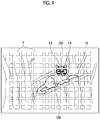
- FIG. 9 is a diagram showing movement of a focus area on a finder monitor.
- FIG. 10 is a flowchart showing an operation flow of an imaging apparatus.
- FIG. 11 is a diagram showing a region set on a touch panel.
- FIG. 12 is a block diagram showing an example of the main functional configuration of a CPU.
- FIG. 13 is a diagram showing an example of a region setting in a case where an imaging apparatus is in a vertical position.
- FIG. 14 is a diagram showing an example of a region setting in a case where an imaging apparatus is in a vertical position.
- FIG. 15 is a flowchart showing a flow of region setting of a coarse movement start region, a fine movement start region, and a non-sensitive region according to a vertical position and a horizontal position of an imaging apparatus.
- FIG. 16 is a block diagram showing an example of the main functional configuration of a CPU.
- FIG. 17 is a diagram showing a swipe operation on a touch panel.
- FIG. 18 is a diagram showing movement of a focus area on a finder monitor.
- FIG. 19 is a flowchart showing a flow of detecting a return operation and changing reception setting.
- FIG. 20 is a diagram showing that a white balance shift image is displayed on a finder monitor.
- FIGS. 1 and 2 are a perspective view and a rear view showing an example (digital camera) of an imaging apparatus, respectively.
- An imaging apparatus 10 is a digital camera that receives light that has passed through a lens by an imaging element, converts the light into a digital signal, and records the digital signal in a recording media as image data of a static image or a video image.
- the imaging apparatus 10 arranges an imaging lens 12 , a strobe 1 and the like on a front surface thereof, and a shutter button 2 , a power/mode switch 3 , a mode dial 4 and the like on an upper surface thereof.
- a rear monitor 30 composed of a liquid crystal (LCD) monitor, a zoom button 5 , a cross button 6 , a MENU/OK button 7 , a play button 8 , a BACK button 9 , a finder 11 , a finder monitor 13 composed of a liquid crystal monitor, an eye sensor 17 and the like are arranged on a rear surface of the camera.
- LCD liquid crystal
- the imaging lens 12 is composed of a retractable zoom lens, and is extended from a camera main body by setting an operation mode of the camera to an imaging mode by the power/mode switch 3 .
- the strobe 1 irradiates the main subject with strobe light.
- the imaging apparatus 10 performs an imaging preparation operation for performing auto focus (AF)/auto exposure (AE) control, and in a case where the shutter button 2 is “full push”, the imaging apparatus captures and records a static image.
- AF auto focus
- AE auto exposure
- the imaging apparatus 10 starts recording the video image, and in a case where the shutter button 2 is “full push” again, the imaging apparatus stops the recording and enters a standby state.
- the rear monitor 30 and the finder monitor 13 function as a part of a graphical user interface by displaying a live view image in the imaging mode, displaying the static image or the video image in the playback mode, and displaying a menu screen.
- a touch panel 31 FIG. 3 is integrally installed on the rear monitor 30 .
- the play button 8 is a button for switching to the playback mode in which the static image or the video image captured and recorded is displayed on the rear monitor 30 .
- buttons/switches Although members specific to the above-described buttons/switches are provided, the functions of those buttons/switches can be realized by operating the touch panel 31 .
- FIG. 3 is a block diagram showing an embodiment of an internal configuration of the imaging apparatus 10 .
- the imaging apparatus 10 records a captured image in a memory card 54 , and the operation of the entire apparatus is centrally controlled by a central processing unit (CPU) 40 .
- CPU central processing unit
- the imaging apparatus 10 is provided with an operation unit 38 such as the shutter button 2 , the power/mode switch 3 , the mode dial 4 , the tele button 5 T, the wide button 5 W, the cross button 6 , the MENU/OK button 7 , the play button 8 , the BACK button 9 , and the like.
- an operation unit 38 such as the shutter button 2 , the power/mode switch 3 , the mode dial 4 , the tele button 5 T, the wide button 5 W, the cross button 6 , the MENU/OK button 7 , the play button 8 , the BACK button 9 , and the like.
- Signals from the operation unit 38 are input to the CPU 40 , and the CPU 40 controls each circuit of the imaging apparatus 10 on the basis of the input signals, and performs, for example, driving control of the imaging element (image sensor) 16 by a sensor driving unit 32 , driving control of a mechanical shutter 15 by a shutter driving unit 33 , driving control of a stop 14 by a stop driving unit 34 , driving control of the imaging lens 12 by the lens driving unit 36 , as well as imaging operation control, image processing control, recording/playing control of image data, display control of the finder monitor 13 and the rear monitor 30 .
- An image signal (image data) read from the imaging element 16 at the time of imaging a video image or a static image is temporarily stored in a memory (synchronous dynamic random access memory (SDRAM)) 48 via an image input controller 22 , or is taken into an AF processing unit 42 , an AE detection unit 44 , and the like.
- SDRAM synchronous dynamic random access memory
- the AE detection unit 44 integrates image data (for example, a pixel value of a G pixel of the entire screen) acquired via the image input controller 22 , or integrates image data in which a central part of the screen and an edge part are weighted differently (a pixel value of G pixel) and the integrated value is output to the CPU 40 .
- the CPU 40 calculates a brightness of a subject (an imaging exposure value (Ev)) from the integrated value input from the AE detection unit 44 .
- the CPU 40 performs the AF control again in a case where the shutter button 2 is pressed at the first stage (half push), calculates the brightness (the imaging Ev value) of the subject in a case where the shutter button 2 is full push, determines an f number of the stop 14 and an exposure time (a shutter speed) by a mechanical shutter 15 according to the program diagram on the basis of the calculated imaging Ev value, and captures (exposure control) the static image.
- the CPU 40 moves the zoom lens forward and backward in the optical axis direction via the lens driving unit 36 in response to a zoom instruction from the zoom button 5 to change the focal length.
- a ROM 47 is a read only memory (ROM) or an electrically erasable programmable read-only memory (EEPROM) that stores a camera control program, defect information of the imaging element 16 , various parameters and tables used for image processing, and the like.
- ROM read only memory
- EEPROM electrically erasable programmable read-only memory
- the image processing unit 24 reads unprocessed image data (RAW data) that is acquired via the image input controller 22 at the time of capturing a video image or a static image and temporarily stored in the memory 48 .
- the image processing unit 24 performs offset processing, pixel interpolation processing (interpolation processing for a phase difference detecting pixel, damaged pixel, and the like), white balance correction, gain control processing including sensitivity correction, gamma-correction processing, synchronization processing (also called “demosaicing”), brightness and color difference signal generation processing, edge enhancement processing, color correction, and the like on the read RAW data.
- the VRAM 50 includes an A region and a B region that record each of image data representing an image for one frame.
- the image data representing the image for one frame is rewritten in the A region and the B region alternately.
- the written image data is read from another region, other than the region where the image data is rewritten, of the A region and the B region of the VRAM 50 .
- the image data read from the VRAM 50 is encoded by a video encoder 28 and output to the finder monitor 13 and the rear monitor 30 provided on a rear surface of a camera.
- the live view image showing the subject image is displayed on the finder monitor 13 and the rear monitor 30 .
- the display of the live view image on the finder monitor 13 or the rear monitor 30 is controlled by the detection of the eye sensor 17 . In a case where it is detected that a user is looking into the finder monitor 13 by the eye sensor 17 , the live view image is displayed on the finder monitor 13 , and in a case where it is detected that the user is not looking into the finder monitor 13 , the live view image is displayed on the rear monitor 30 .
- the eye sensor 17 is a sensor that detects whether or not the user is looking into the finder monitor 13 .
- the eye sensor 17 is composed of, for example, an infrared sensor.
- the touch panel 31 is provided integrally with the rear monitor 30 .
- the touch panel 31 detects a touch of a user finger 120 as an operation by the user.
- the touch panel 31 detects contact by various methods such as a resistance film method and a capacitance method.
- the touch sensor input unit 49 analyzes a touch position of the user finger 120 on the touch panel 31 and the movement of the user finger 120 from the signal from the touch panel 31 , and outputs the analysis result.
- a compression and expansion processing unit 26 performs compression processing on the brightness data (Y) and the color difference data (Cb), (Cr) processed by the image processing unit 24 and stored in the memory 48 at the time of recording a static image or a video image.
- a static image it is compressed in, for example, a joint photographic coding experts group (JPEG) format
- JPEG joint photographic coding experts group
- H.264 H.264 format
- the compression and expansion processing unit 26 also performs expansion processing on the compressed image data obtained from the memory card 54 via the media controller 52 in the playback mode.
- the media controller 52 records and reads the compressed image data to and from the memory card 54 .
- a posture sensor 51 is a sensor that detects the posture of the imaging apparatus 10 , and is composed of, for example, a gyro sensor.
- the posture sensor 51 detects whether the imaging apparatus 10 is in the horizontal position or the vertical position according to the imaging posture of the user. In a case where the imaging apparatus 10 is in the vertical position, the posture sensor 51 can detect whether the finder 13 is in the vertical position on the right side with respect to the imaging direction or the finder 13 is in the vertical position on the left side with respect to the imaging direction.
- FIG. 4 is a block diagram showing an example of the main functional configuration of the CPU 40 of the embodiment.
- the CPU 40 of the embodiment has sensitivity setting unit 101 and a movement control unit 103 .
- the sensitivity setting unit 101 sets the sensitivity in a case of moving the index.
- the sensitivity setting unit 101 sets the sensitivity of the index that moves according to the swipe operation received on the touch panel 31 .
- the sensitivity is the moving distance of the index according to the moving distance of the swipe operation received on the touch panel 31 .
- the index is a mark or the like that is superimposed and displayed on the live view image, and it is possible to instruct the imaging condition or the image processing condition according to a superimposed and displayed position.
- the index shows a focus area.
- the index shows the shift amount of the white balance shift.
- the touch panel 31 is configured with a coarse movement start region (the first region) W 1 and a fine movement start region (the second region) W 2 .
- the coarse movement start region W 1 and the fine movement start region W 2 are provided so as to divide a short side L 2 of the touch panel 31 into two equal parts.
- FIG. 6 is a diagram showing the swipe operation on the touch panel 31 .
- FIG. 7 is a diagram showing movement of the focus area F on the finder monitor 13 in conjunction with the swipe operation shown in FIG. 6 .
- a candidate of the focus area F on the finder monitor 13 is displayed in FIG. 7 , the candidate of the focus area F may not be displayed on the actual finder monitor 13 .
- the user uses the finger 120 to perform the swipe operation on the touch panel 31 .
- the contact operation of the finger 120 is performed.
- the finger 120 performs the swipe operation along the arrow 122 .
- the position of the focus area F moves from F 3 to F 4 along the arrow 124 in the finder monitor 13 .
- the movement of the focus area F is performed by the fine movement sensitivity.
- One processing unit may be configured with one of the various processors or may be configured with two or more processors of the same type or different types (for example, a plurality of FPGAs or a combination of a CPU and an FPGA).
- a plurality of processing units may be configured with one processor.
- a first aspect is configuring one processor with a combination of one or more CPUs and software and implementing functions of a plurality of processing units by the processor as represented by a computer such as a client and a server.
- a second aspect is using a processor that implements the function of the whole system including a plurality of processing units by one integrated circuit (IC) chip as represented by a system on chip (SoC) and the like.
- IC integrated circuit
- SoC system on chip
- the touch panel 31 is provided with a non-sensitive region (third region) W 3 in addition to the coarse movement start region W 1 and the fine movement start region W 2 .
- FIG. 11 is a diagram showing a region set on the touch panel 31 .
- the parts already described in FIG. 5 are designated by the same reference signs and the description thereof will be omitted.
- the touch panel 31 is provided with a coarse movement start region W 1 , a fine movement start region W 2 , and a non-sensitive region W 3 .
- the non-sensitive region W 3 is a region in which the swipe operation is not detected. By providing the non-sensitive region W 3 , it is possible to suppress the index from moving accidentally even in a case where the user unintentionally touches the touch panel 31 .
- the user can easily perform the swipe operation in the coarse movement start region W 1 and the fine movement start region W 2 even in a case where the imaging apparatus 10 is in the vertical position. Further, by providing the non-sensitive region W 3 at the position shown in the Figs, it is possible to suppress the index from moving accidentally by touching part of the face with the touch panel 31 in a case where the user looks into the finder 11 .
- the region setting unit 105 determines whether or not the finder 11 is in the vertical position on the left side in the imaging direction on the basis of the detection result of the posture sensor 51 (step S 23 ). In a case of determining that the finder 11 is on the left side, the region setting unit 105 sets the coarse movement start region W 1 and the fine movement start region W 2 for the vertical position (the finder 11 is on the left side) (step S 24 ).
- the example shown in FIG. 13 is an example of setting the coarse movement start region W 1 and the fine movement start region W 2 for the vertical position (the finder 11 is on the left side).
- the region setting unit 105 sets the coarse movement start region W 1 and the fine movement start region W 2 for the vertical position (the finder 11 is on the right side) (step S 25 ).
- the example shown in FIG. 14 is an example of setting the coarse movement start region W 1 and the fine movement start region W 2 for the vertical position (the finder 11 is on the right side).
- FIG. 16 is a block diagram showing an example of the main functional configuration of the CPU 40 of the embodiment.
- the parts already described in FIG. 4 are designated by the same reference signs and the description thereof will be omitted.
- FIG. 19 is a flowchart showing a flow of detecting the return operation and changing the reception setting.
- the forced sensitivity setting unit 107 determines the return operation using the threshold value and forcibly changes the sensitivity, so that the user can easily move the index with different sensitivity.
- the sensitivity setting unit 101 may set the sensitivity according to the number of fingers 120 touching the touch panel 31 .
- the sensitivity setting unit 101 sets the first sensitivity in a case where the contact operation is performed by the first number of fingers 120 , and sets the second sensitivity in a case where the contact operation is performed by the second number of fingers 120 .
- the white balance shift image (WB shift image) 131 superimposed and displayed on the live view image, each of a red axis (R), a blue axis (B), a green axis (G), and a yellow axis (Y) is shown, and the white balance shift amount is adjusted by moving an index S. Specifically, by moving the index S, the white balance shift amount is adjusted, and the white balance shift amount is reflected in the live view image, so that the user can perform the intended white balance adjustment.
- the index can be moved quickly and accurately on the WB shift image by moving the index with the fine movement sensitivity and the coarse movement sensitivity as intended by the user.
Priority Applications (2)
| Application Number | Priority Date | Filing Date | Title |
|---|---|---|---|
| US17/504,040 US11635856B2 (en) | 2018-06-27 | 2021-10-18 | Imaging apparatus, imaging method, and program |
| US18/182,755 US11954290B2 (en) | 2018-06-27 | 2023-03-13 | Imaging apparatus, imaging method, and program |
Applications Claiming Priority (4)
| Application Number | Priority Date | Filing Date | Title |
|---|---|---|---|
| JPJP2018-122043 | 2018-06-27 | ||
| JP2018-122043 | 2018-06-27 | ||
| JP2018122043 | 2018-06-27 | ||
| PCT/JP2019/021101 WO2020003862A1 (ja) | 2018-06-27 | 2019-05-28 | 撮像装置、撮像方法、及びプログラム |
Related Parent Applications (1)
| Application Number | Title | Priority Date | Filing Date |
|---|---|---|---|
| PCT/JP2019/021101 Continuation WO2020003862A1 (ja) | 2018-06-27 | 2019-05-28 | 撮像装置、撮像方法、及びプログラム |
Related Child Applications (1)
| Application Number | Title | Priority Date | Filing Date |
|---|---|---|---|
| US17/504,040 Continuation US11635856B2 (en) | 2018-06-27 | 2021-10-18 | Imaging apparatus, imaging method, and program |
Publications (2)
| Publication Number | Publication Date |
|---|---|
| US20210081074A1 US20210081074A1 (en) | 2021-03-18 |
| US11216118B2 true US11216118B2 (en) | 2022-01-04 |
Family
ID=68985611
Family Applications (3)
| Application Number | Title | Priority Date | Filing Date |
|---|---|---|---|
| US17/106,490 Active US11216118B2 (en) | 2018-06-27 | 2020-11-30 | Imaging apparatus, imaging method, and program |
| US17/504,040 Active US11635856B2 (en) | 2018-06-27 | 2021-10-18 | Imaging apparatus, imaging method, and program |
| US18/182,755 Active US11954290B2 (en) | 2018-06-27 | 2023-03-13 | Imaging apparatus, imaging method, and program |
Family Applications After (2)
| Application Number | Title | Priority Date | Filing Date |
|---|---|---|---|
| US17/504,040 Active US11635856B2 (en) | 2018-06-27 | 2021-10-18 | Imaging apparatus, imaging method, and program |
| US18/182,755 Active US11954290B2 (en) | 2018-06-27 | 2023-03-13 | Imaging apparatus, imaging method, and program |
Country Status (4)
| Country | Link |
|---|---|
| US (3) | US11216118B2 (zh) |
| JP (2) | JP6880326B2 (zh) |
| CN (1) | CN112352418B (zh) |
| WO (1) | WO2020003862A1 (zh) |
Cited By (1)
| Publication number | Priority date | Publication date | Assignee | Title |
|---|---|---|---|---|
| US20220035480A1 (en) * | 2018-06-27 | 2022-02-03 | Fujifilm Corporation | Imaging apparatus, imaging method, and program |
Families Citing this family (1)
| Publication number | Priority date | Publication date | Assignee | Title |
|---|---|---|---|---|
| WO2023053556A1 (ja) * | 2021-09-30 | 2023-04-06 | 富士フイルム株式会社 | 情報処理装置、情報処理方法、及びプログラム |
Citations (17)
| Publication number | Priority date | Publication date | Assignee | Title |
|---|---|---|---|---|
| US20090256817A1 (en) * | 2008-02-28 | 2009-10-15 | New York University | Method and apparatus for providing input to a processor, and a sensor pad |
| JP2010160581A (ja) | 2009-01-06 | 2010-07-22 | Olympus Imaging Corp | ユーザインタフェース装置、カメラ、ユーザインタフェース方法およびユーザインタフェース用プログラム |
| JP2012203143A (ja) | 2011-03-24 | 2012-10-22 | Olympus Imaging Corp | 表示装置 |
| CN103197770A (zh) | 2013-04-01 | 2013-07-10 | 深圳数字电视国家工程实验室股份有限公司 | 一种电视遥控器模拟鼠标操作的方法及装置 |
| US20160011720A1 (en) * | 2014-07-10 | 2016-01-14 | Thomas Christian Walther | Multi-Touch Interface for Blind Real-Time Interaction |
| CN105824361A (zh) | 2016-03-11 | 2016-08-03 | 合肥联宝信息技术有限公司 | 一种笔记本电脑及控制鼠标的方法 |
| WO2016147697A1 (ja) | 2015-03-13 | 2016-09-22 | オリンパス株式会社 | 内視鏡画像表示装置、内視鏡画像表示方法及び内視鏡画像表示プログラム |
| US20170060326A1 (en) * | 2015-08-31 | 2017-03-02 | Hideep Inc. | Pressure detector capable of adjusting pressure sensitivity and touch input device including the same |
| CN106980438A (zh) | 2017-03-20 | 2017-07-25 | 联想(北京)有限公司 | 光标控制方法、装置及系统 |
| JP2017174363A (ja) | 2016-03-25 | 2017-09-28 | ヤマハ株式会社 | 設定装置及び方法 |
| JP2018013745A (ja) | 2016-07-23 | 2018-01-25 | キヤノン株式会社 | 電子機器およびその制御方法 |
| US20180063418A1 (en) * | 2016-08-30 | 2018-03-01 | Canon Kabushiki Kaisha | Electronic apparatus, control method therefor, and storage medium |
| JP2018085570A (ja) | 2016-11-21 | 2018-05-31 | キヤノン株式会社 | 撮像装置、撮像方法及びプログラム |
| US20180220062A1 (en) | 2017-01-30 | 2018-08-02 | Canon Kabushiki Kaisha | Image capture apparatus and control method for the same |
| US20190034147A1 (en) * | 2017-07-31 | 2019-01-31 | Intel Corporation | Methods and apparatus to detect user-facing screens of multi-screen devices |
| US20200007750A1 (en) * | 2018-06-29 | 2020-01-02 | Canon Kabushiki Kaisha | Electronic apparatus and control method for electronic apparatus |
| US20200257445A1 (en) * | 2017-11-07 | 2020-08-13 | Huawei Technologies Co., Ltd. | Touch control method and apparatus |
Family Cites Families (13)
| Publication number | Priority date | Publication date | Assignee | Title |
|---|---|---|---|---|
| JP2007325051A (ja) * | 2006-06-02 | 2007-12-13 | Fujifilm Corp | 撮影装置および方法並びにプログラム |
| US7564449B2 (en) | 2006-06-16 | 2009-07-21 | Cirque Corporation | Method of scrolling that is activated by touchdown in a predefined location on a touchpad that recognizes gestures for controlling scrolling functions |
| JP5613005B2 (ja) * | 2010-10-18 | 2014-10-22 | オリンパスイメージング株式会社 | カメラ |
| JP2012191570A (ja) * | 2011-03-14 | 2012-10-04 | Seiko Epson Corp | 撮影装置、その制御方法及びプログラム |
| JP2013025503A (ja) | 2011-07-19 | 2013-02-04 | Canon Inc | 電子機器及びその制御方法、プログラム、並びに記憶媒体 |
| US8743055B2 (en) | 2011-10-13 | 2014-06-03 | Panasonic Corporation | Hybrid pointing system and method |
| JP2014067316A (ja) * | 2012-09-27 | 2014-04-17 | Canon Inc | 表示制御装置 |
| JP5995637B2 (ja) * | 2012-10-04 | 2016-09-21 | キヤノン株式会社 | 撮像装置、撮像装置の制御方法、プログラム、記憶媒体 |
| JP2014215885A (ja) * | 2013-04-26 | 2014-11-17 | 株式会社東芝 | 情報処理装置、タッチパッドの感度調整方法およびプログラム |
| WO2017085983A1 (ja) | 2015-11-17 | 2017-05-26 | ソニー株式会社 | 制御装置、制御方法、およびプログラム |
| CN206805468U (zh) * | 2017-05-11 | 2017-12-26 | 安徽师范大学 | 一种头戴式智能鼠标 |
| CN107707955A (zh) * | 2017-08-30 | 2018-02-16 | 上海与德科技有限公司 | 一种显示器上的光标控制方法及智能设备 |
| WO2020003862A1 (ja) * | 2018-06-27 | 2020-01-02 | 富士フイルム株式会社 | 撮像装置、撮像方法、及びプログラム |
-
2019
- 2019-05-28 WO PCT/JP2019/021101 patent/WO2020003862A1/ja active Application Filing
- 2019-05-28 CN CN201980042597.7A patent/CN112352418B/zh active Active
- 2019-05-28 JP JP2020527303A patent/JP6880326B2/ja active Active
-
2020
- 2020-11-30 US US17/106,490 patent/US11216118B2/en active Active
-
2021
- 2021-04-30 JP JP2021077003A patent/JP7152557B2/ja active Active
- 2021-10-18 US US17/504,040 patent/US11635856B2/en active Active
-
2023
- 2023-03-13 US US18/182,755 patent/US11954290B2/en active Active
Patent Citations (22)
| Publication number | Priority date | Publication date | Assignee | Title |
|---|---|---|---|---|
| US20090256817A1 (en) * | 2008-02-28 | 2009-10-15 | New York University | Method and apparatus for providing input to a processor, and a sensor pad |
| JP2010160581A (ja) | 2009-01-06 | 2010-07-22 | Olympus Imaging Corp | ユーザインタフェース装置、カメラ、ユーザインタフェース方法およびユーザインタフェース用プログラム |
| JP2012203143A (ja) | 2011-03-24 | 2012-10-22 | Olympus Imaging Corp | 表示装置 |
| CN103197770A (zh) | 2013-04-01 | 2013-07-10 | 深圳数字电视国家工程实验室股份有限公司 | 一种电视遥控器模拟鼠标操作的方法及装置 |
| US20160011720A1 (en) * | 2014-07-10 | 2016-01-14 | Thomas Christian Walther | Multi-Touch Interface for Blind Real-Time Interaction |
| US20180013973A1 (en) * | 2015-03-13 | 2018-01-11 | Olympus Corporation | Endoscope image display apparatus, endoscope image display method and endoscope image display program |
| WO2016147697A1 (ja) | 2015-03-13 | 2016-09-22 | オリンパス株式会社 | 内視鏡画像表示装置、内視鏡画像表示方法及び内視鏡画像表示プログラム |
| US20170060326A1 (en) * | 2015-08-31 | 2017-03-02 | Hideep Inc. | Pressure detector capable of adjusting pressure sensitivity and touch input device including the same |
| CN105824361A (zh) | 2016-03-11 | 2016-08-03 | 合肥联宝信息技术有限公司 | 一种笔记本电脑及控制鼠标的方法 |
| JP2017174363A (ja) | 2016-03-25 | 2017-09-28 | ヤマハ株式会社 | 設定装置及び方法 |
| US20190158761A1 (en) | 2016-07-23 | 2019-05-23 | Canon Kabushiki Kaisha | Electronic apparatus and method for controlling the same |
| JP2018013745A (ja) | 2016-07-23 | 2018-01-25 | キヤノン株式会社 | 電子機器およびその制御方法 |
| US20180063418A1 (en) * | 2016-08-30 | 2018-03-01 | Canon Kabushiki Kaisha | Electronic apparatus, control method therefor, and storage medium |
| JP2018036802A (ja) | 2016-08-30 | 2018-03-08 | キヤノン株式会社 | 電子機器およびその制御方法 |
| CN107797714A (zh) | 2016-08-30 | 2018-03-13 | 佳能株式会社 | 电子装置及其控制方法和存储介质 |
| JP2018085570A (ja) | 2016-11-21 | 2018-05-31 | キヤノン株式会社 | 撮像装置、撮像方法及びプログラム |
| US20180220062A1 (en) | 2017-01-30 | 2018-08-02 | Canon Kabushiki Kaisha | Image capture apparatus and control method for the same |
| JP2018125612A (ja) | 2017-01-30 | 2018-08-09 | キヤノン株式会社 | 撮像装置及びその制御方法 |
| CN106980438A (zh) | 2017-03-20 | 2017-07-25 | 联想(北京)有限公司 | 光标控制方法、装置及系统 |
| US20190034147A1 (en) * | 2017-07-31 | 2019-01-31 | Intel Corporation | Methods and apparatus to detect user-facing screens of multi-screen devices |
| US20200257445A1 (en) * | 2017-11-07 | 2020-08-13 | Huawei Technologies Co., Ltd. | Touch control method and apparatus |
| US20200007750A1 (en) * | 2018-06-29 | 2020-01-02 | Canon Kabushiki Kaisha | Electronic apparatus and control method for electronic apparatus |
Non-Patent Citations (4)
| Title |
|---|
| An Office Action issued by the State Intellectual Property Office of the People's Republic of China dated Sep. 30, 2021, which corresponds to Chinese Patent Application No. CN 201980042597.7. |
| An Office Action; "Notice of Reasons for Refusal," mailed by the Japanese Patent Office dated Jan. 12, 2021, which corresponds to Japanese Patent Application No. 2020-527303 and is related to U.S. Appl. No. 17/106,490 with English language translation. |
| International Preliminary Report on Patentability issued in PCT/JP2019/021101; completed Mar. 6, 2020. |
| International Search Report issued in PCT/JP2019/021101; dated Aug. 13, 2019. |
Cited By (3)
| Publication number | Priority date | Publication date | Assignee | Title |
|---|---|---|---|---|
| US20220035480A1 (en) * | 2018-06-27 | 2022-02-03 | Fujifilm Corporation | Imaging apparatus, imaging method, and program |
| US11635856B2 (en) * | 2018-06-27 | 2023-04-25 | Fujifilm Corporation | Imaging apparatus, imaging method, and program |
| US11954290B2 (en) | 2018-06-27 | 2024-04-09 | Fujifilm Corporation | Imaging apparatus, imaging method, and program |
Also Published As
| Publication number | Publication date |
|---|---|
| US11635856B2 (en) | 2023-04-25 |
| US11954290B2 (en) | 2024-04-09 |
| CN112352418A (zh) | 2021-02-09 |
| US20210081074A1 (en) | 2021-03-18 |
| JP7152557B2 (ja) | 2022-10-12 |
| WO2020003862A1 (ja) | 2020-01-02 |
| JP6880326B2 (ja) | 2021-06-02 |
| US20230217096A1 (en) | 2023-07-06 |
| US20220035480A1 (en) | 2022-02-03 |
| CN112352418B (zh) | 2023-11-21 |
| JP2021132383A (ja) | 2021-09-09 |
| JPWO2020003862A1 (ja) | 2021-04-22 |
Similar Documents
| Publication | Publication Date | Title |
|---|---|---|
| US11954290B2 (en) | Imaging apparatus, imaging method, and program | |
| US10200590B2 (en) | Image pickup apparatus and method of controlling the same | |
| KR100914084B1 (ko) | 촬상 장치 및 촬상 방법 | |
| JP4582212B2 (ja) | 撮像装置及びプログラム | |
| US7978968B2 (en) | Auto focus device | |
| JP2009225027A (ja) | 撮像装置、撮像制御方法、及びプログラム | |
| JP5409483B2 (ja) | 撮像装置 | |
| US20230276017A1 (en) | Video creation method | |
| JP4437988B2 (ja) | 電子カメラ | |
| US20220279106A1 (en) | Video creation method | |
| JP6172973B2 (ja) | 画像処理装置 | |
| JP4981955B2 (ja) | 撮像装置、及びその制御方法 | |
| WO2014129533A1 (ja) | 撮像装置及び制御プログラム並びに露出量制御方法 | |
| JP7001087B2 (ja) | 撮像装置 | |
| JP4785548B2 (ja) | 撮像装置、及びその制御方法 | |
| US20110032390A1 (en) | Digital photographing apparatus and moving picture capturing method performed by the same | |
| US11871106B2 (en) | Imaging apparatus, imaging method, and program | |
| WO2022071271A1 (ja) | 撮像装置、画像処理方法及び画像処理プログラム | |
| JP5225477B2 (ja) | 撮像装置、及びその制御方法 | |
| JP5965653B2 (ja) | 追尾装置及び追尾方法 | |
| US20230419459A1 (en) | Image processing apparatus, imaging apparatus, image processing method, and recording medium background | |
| JP2011004220A (ja) | デジタルカメラ | |
| JP2007067997A (ja) | カメラ機器及びその操作方法 | |
| JP2006054803A (ja) | デジタル撮影機器、デジタル撮影機器の画像表示方法、プログラム、および記録媒体 |
Legal Events
| Date | Code | Title | Description |
|---|---|---|---|
| AS | Assignment |
Owner name: FUJIFILM CORPORATION, JAPAN Free format text: ASSIGNMENT OF ASSIGNORS INTEREST;ASSIGNORS:SUGIHARA, YUKI;KOBAYASHI, MASARU;ISHIDA, KAZUKI;AND OTHERS;REEL/FRAME:054488/0800 Effective date: 20201020 |
|
| FEPP | Fee payment procedure |
Free format text: ENTITY STATUS SET TO UNDISCOUNTED (ORIGINAL EVENT CODE: BIG.); ENTITY STATUS OF PATENT OWNER: LARGE ENTITY |
|
| STPP | Information on status: patent application and granting procedure in general |
Free format text: DOCKETED NEW CASE - READY FOR EXAMINATION |
|
| STPP | Information on status: patent application and granting procedure in general |
Free format text: NOTICE OF ALLOWANCE MAILED -- APPLICATION RECEIVED IN OFFICE OF PUBLICATIONS |
|
| STPP | Information on status: patent application and granting procedure in general |
Free format text: PUBLICATIONS -- ISSUE FEE PAYMENT VERIFIED |
|
| STCF | Information on status: patent grant |
Free format text: PATENTED CASE |
|
| STPP | Information on status: patent application and granting procedure in general |
Free format text: WITHDRAW FROM ISSUE AWAITING ACTION |
|
| STPP | Information on status: patent application and granting procedure in general |
Free format text: AWAITING TC RESP., ISSUE FEE NOT PAID |
|
| STPP | Information on status: patent application and granting procedure in general |
Free format text: NOTICE OF ALLOWANCE MAILED -- APPLICATION RECEIVED IN OFFICE OF PUBLICATIONS |
|
| STPP | Information on status: patent application and granting procedure in general |
Free format text: PUBLICATIONS -- ISSUE FEE PAYMENT VERIFIED |
|
| STCF | Information on status: patent grant |
Free format text: PATENTED CASE |