US10917536B2 - Image sensor unit and image reading device - Google Patents
Image sensor unit and image reading device Download PDFInfo
- Publication number
- US10917536B2 US10917536B2 US16/575,507 US201916575507A US10917536B2 US 10917536 B2 US10917536 B2 US 10917536B2 US 201916575507 A US201916575507 A US 201916575507A US 10917536 B2 US10917536 B2 US 10917536B2
- Authority
- US
- United States
- Prior art keywords
- erecting equal
- lens array
- image sensor
- magnification
- magnification lens
- Prior art date
- Legal status (The legal status is an assumption and is not a legal conclusion. Google has not performed a legal analysis and makes no representation as to the accuracy of the status listed.)
- Active
Links
Images


Classifications
-
- H—ELECTRICITY
- H04—ELECTRIC COMMUNICATION TECHNIQUE
- H04N—PICTORIAL COMMUNICATION, e.g. TELEVISION
- H04N1/00—Scanning, transmission or reproduction of documents or the like, e.g. facsimile transmission; Details thereof
- H04N1/024—Details of scanning heads ; Means for illuminating the original
- H04N1/028—Details of scanning heads ; Means for illuminating the original for picture information pick-up
- H04N1/02815—Means for illuminating the original, not specific to a particular type of pick-up head
- H04N1/02845—Means for illuminating the original, not specific to a particular type of pick-up head using an elongated light source, e.g. tubular lamp, LED array
-
- H—ELECTRICITY
- H04—ELECTRIC COMMUNICATION TECHNIQUE
- H04N—PICTORIAL COMMUNICATION, e.g. TELEVISION
- H04N1/00—Scanning, transmission or reproduction of documents or the like, e.g. facsimile transmission; Details thereof
- H04N1/024—Details of scanning heads ; Means for illuminating the original
- H04N1/028—Details of scanning heads ; Means for illuminating the original for picture information pick-up
- H04N1/02815—Means for illuminating the original, not specific to a particular type of pick-up head
- H04N1/02885—Means for compensating spatially uneven illumination, e.g. an aperture arrangement
-
- H—ELECTRICITY
- H04—ELECTRIC COMMUNICATION TECHNIQUE
- H04N—PICTORIAL COMMUNICATION, e.g. TELEVISION
- H04N1/00—Scanning, transmission or reproduction of documents or the like, e.g. facsimile transmission; Details thereof
- H04N1/024—Details of scanning heads ; Means for illuminating the original
- H04N1/028—Details of scanning heads ; Means for illuminating the original for picture information pick-up
- H04N1/02815—Means for illuminating the original, not specific to a particular type of pick-up head
- H04N1/02895—Additional elements in the illumination means or cooperating with the illumination means, e.g. filters
-
- H—ELECTRICITY
- H04—ELECTRIC COMMUNICATION TECHNIQUE
- H04N—PICTORIAL COMMUNICATION, e.g. TELEVISION
- H04N1/00—Scanning, transmission or reproduction of documents or the like, e.g. facsimile transmission; Details thereof
- H04N1/024—Details of scanning heads ; Means for illuminating the original
- H04N1/028—Details of scanning heads ; Means for illuminating the original for picture information pick-up
- H04N1/03—Details of scanning heads ; Means for illuminating the original for picture information pick-up with photodetectors arranged in a substantially linear array
- H04N1/0306—Details of scanning heads ; Means for illuminating the original for picture information pick-up with photodetectors arranged in a substantially linear array using a plurality of optical elements arrayed in the main scan direction, e.g. an array of lenses
-
- G—PHYSICS
- G02—OPTICS
- G02B—OPTICAL ELEMENTS, SYSTEMS OR APPARATUS
- G02B5/00—Optical elements other than lenses
- G02B5/18—Diffraction gratings
- G02B5/1814—Diffraction gratings structurally combined with one or more further optical elements, e.g. lenses, mirrors, prisms or other diffraction gratings
-
- H—ELECTRICITY
- H04—ELECTRIC COMMUNICATION TECHNIQUE
- H04N—PICTORIAL COMMUNICATION, e.g. TELEVISION
- H04N2201/00—Indexing scheme relating to scanning, transmission or reproduction of documents or the like, and to details thereof
- H04N2201/0077—Types of the still picture apparatus
- H04N2201/0081—Image reader
Definitions
- the present invention relates to an image sensor unit and an image reading device in which the image sensor unit is used.
- An image reading device such as scanners are known to use an erecting equal-magnification imaging system.
- the use of an erecting equal-magnification imaging system can reduce the size of the image sensor unit better than reduction imaging optical systems.
- An image sensor unit using an erecting equal-magnification imaging system is primarily comprised of a linear light source, an erecting equal-magnification lens array, and a linear image sensor.
- SELFOC lens array (hereinafter, SLA, SELFOC is a registered trademark of Nippon Sheet Glass Co. Ltd.), which is a form of rod lens array including a large number of rod lenses arranged in the main scanning direction and integrated with each other, each of the rod lenses being embodied by a columnar graded index glass rod having a higher refraction index at the center.
- Other known examples include a resin rod lens array including a large number of similarly graded index rod lenses with a graded index inside arranged and integrated with each other, and a lens array plate or a stack thereof produced by forming a large number of convex lenses on the surface of a dielectric substrate plate.
- a color image sensor unit for reading a color image In a color image sensor unit for reading a color image, on-chip filters for RGB, etc. are formed on the sensor surface in order to provide a signal output from the light receiving device with color information.
- a spectral device such as a diffraction grating is provided in front of the sensor surface to separate the light into the RGB colors, and the lights subjected to color separation are caused to be incident on the R (red), G (green), and B (blue) light receiving devices, respectively (see, for example, patent literature 1).
- each of the R, G, B lights may arrive at the light receiving device of another color with a certain light intensity distribution (such a state is referred to as “color mixture”) with the result that the resolution may be lowered, if a spectral device is merely provided in front of the sensor surface.
- the present invention addresses the above-described issue, and a general purpose thereof is to provide a technology of preventing, in an image sensor unit including a color separation optical system, the light dispersed from producing color mixture on the sensor surface.
- An image sensor unit includes: a linear light source that illuminates a document with a light; a first erecting equal-magnification lens array and a second erecting equal-magnification lens array arranged in the stated order away from the document so as to receive a light reflected from the document and form an erecting equal-magnification image; a visual field restriction device provided on an intermediate imaging plane between the first erecting equal-magnification lens array and the second erecting equal-magnification lens array; a spectral device that disperses a light output from the second erecting equal-magnification lens array; and a linear image sensor that receives a light dispersed by the spectral device.
- the visual field restriction device is configured to restrict a visual field on the intermediate imaging plane in the sub-scanning direction.
- the visual field restriction device may be comprised of a slit that extends in the main scanning direction and has a predetermined width in the sub-scanning direction.
- the visual field restriction device may be comprised of a mirror that extends in the main scanning direction and has a predetermined width in the sub-scanning direction.
- the first erecting equal-magnification lens array and the second erecting equal-magnification lens array may be arranged such that an angle formed by the respective optical axes is a predetermined angle.
- the linear light source outputs a light with a first wavelength at first point of time and outputs a light with a second wavelength different from the first wavelength at a second point of time.
- the image reading device includes: the image sensor unit as defined above; and an image processing unit that processes data detected by the image sensor unit.
- FIG. 1 shows an image reading device in which an image sensor unit according to the embodiment of the present invention is used
- FIG. 2 is a schematic view of an erecting equal-magnification imaging system according to the first comparative example
- FIG. 3 shows a relative light intensity distribution on the sensor surface in the erecting equal-magnification imaging system according to the first comparative example
- FIG. 4 is a schematic view of an erecting equal-magnification imaging system according to the second comparative example
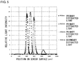
- FIG. 5 shows a relative light intensity distribution on the sensor surface in the erecting equal-magnification imaging system according to the second comparative example
- FIG. 6 is a schematic view of an erecting equal-magnification imaging system according to the third comparative example.
- FIG. 7 shows a relative light intensity distribution on the sensor surface in the erecting equal-magnification imaging system according to the third comparative example
- FIG. 8 is a schematic view of an erecting equal-magnification imaging system according to the fourth comparative example.
- FIG. 9 shows a relative light intensity distribution on the sensor surface in the erecting equal-magnification imaging system according to the fourth comparative example.
- FIGS. 10A and 10B are figures for illustrating the definition of color mixture
- FIG. 11 is a schematic view of the erecting equal-magnification imaging system in the image sensor unit according to the embodiment of the present invention described with reference to FIG. 1 ;
- FIG. 12 shows a relative light intensity distribution on the sensor surface that occurs when the slit width w is 50 ⁇ m in the erecting equal-magnification imaging system shown in FIG. 11 ;
- FIG. 13 shows a relative light intensity distribution on the sensor surface that occurs when the slit width w is 75 ⁇ m in the erecting equal-magnification imaging system shown in FIG. 11 ;
- FIG. 14 shows a relative light intensity distribution on the sensor surface that occurs when the slit width w is 100 ⁇ m in the erecting equal-magnification imaging system shown in FIG. 11 ;
- FIG. 15 shows a relative light intensity distribution on the sensor surface that occurs when the slit width w is 125 ⁇ m in the erecting equal-magnification imaging system shown in FIG. 11 ;
- FIG. 16 shows the degree of color mixture in the simulation result shown in FIGS. 12, 13, 14 and 15 ;
- FIG. 17 is a schematic view of an erecting equal-magnification imaging system in an image sensor unit according to another embodiment of the present invention.
- FIG. 18 shows an example of the mirror
- FIG. 19 shows another example of the mirror
- FIG. 20 shows a relative light intensity distribution on the sensor surface in the erecting equal-magnification imaging system shown in FIG. 17 ;
- FIG. 21 is a schematic view of an erecting equal-magnification imaging system in an image sensor unit according to still another embodiment of the present invention.
- FIG. 22 shows a specification of the dimension of the erecting equal-magnification lens array plate used in the simulation
- FIG. 23 shows a relative light intensity distribution on the sensor surface in the erecting equal-magnification imaging system shown in FIG. 21 ;
- FIG. 24 shows a relative light intensity distribution on the sensor surface that occurs when a linear light source outputting lights with five wavelengths 410 nm, 450 nm, 550 nm, 650 nm, and 850 nm is used in the erecting equal-magnification imaging system shown in FIG. 11 ;
- FIGS. 25A, 25B and 25C show relative light intensity distributions on the sensor surface that occur when the linear light source outputs lights at three different points of time.
- FIG. 26 is a schematic view of the sensor surface of the linear image sensor.
- FIG. 1 shows an image reading device 100 in which an image sensor unit 10 according to the embodiment of the present invention is used.
- the image sensor unit 10 according to the embodiment is an image sensor unit including a color separation optical system.
- the image sensor unit 10 is elongated in a direction perpendicular to the paper surface, and FIG. 1 shows a cross section of the image sensor unit 10 revealed by cutting the image sensor unit 10 by a plane parallel to the paper surface.
- the image reading device 100 includes an image sensor unit 10 , a plate glass document table 13 configured to support a document G on a top surface 131 , a driving mechanism (not shown) for driving the image sensor unit 10 for scanning, and an image processing unit (not shown) for processing data read by the image sensor unit 10 .
- the image sensor unit 10 includes a linear light source 14 for illuminating the document G placed on the plate glass document table 13 , an erecting equal-magnification imaging system 11 for condensing a light reflected from the document G, a linear image sensor 15 for receiving a light condensed by the erecting equal-magnification imaging system 11 , and a housing (not shown) that fixes these components.
- the linear light source 14 , the erecting equal-magnification imaging system 11 , and the linear image sensor 15 are fixed by the housing (not shown) so as to maintain predetermined relative positions.
- the direction of the arrow (the direction parallel to the paper surface) represents the sub-scanning direction
- the direction perpendicular to the sub-scanning direction (the direction perpendicular to the paper surface) is the main scanning direction.
- the linear light source 14 is elongated in the main scanning direction and illuminates the document G line by line along the main scanning direction.
- the linear light source 14 may emit lights with three wavelengths (e.g., 650 nm, 550 nm, and 450 nm) corresponding to the RGB colors. As described in FIG.
- the linear image sensor 15 may be configured such that a plurality of light receiving devices (photoelectric transducer) 301 are arranged in a tile pattern along the main scanning direction and the sub-scanning direction on a sensor surface of a substrate 61 elongated in the main scanning direction, and such that the longitudinal direction of the arrangement is parallel to the main scanning direction.
- ten light receiving devices (photoelectric transducers) 301 are arranged in the sub-scanning direction. The arrangement may not be as illustrated provided that as many devices as the number of colors sought to be separated in one sitting or more are arranged.
- the light receiving device (photoelectric transducer) 301 may be configured such that on-chip filters corresponding to the RGB colors are formed on the surface.
- the optical axis Ax of the erecting equal-magnification imaging system 11 is arranged to be perpendicular to the principal surface of the plate glass document table 13 .
- the linear light source 14 is arranged such that the illumination light illuminates an area F including an intersection f between the optical axis Ax of the erecting equal-magnification imaging system 11 and the top surface 131 of the plate glass document table 13 evenly and most brightly.
- the linear image sensor 15 is arranged such that the sensor surface (light receiving surface) is positioned on the ultimate imaging plane of the erecting equal-magnification imaging system 11 .
- the document G is read by causing the illuminating light from the linear light source 14 to irradiate the document G via the plate glass document table 13 , and causing the erecting equal-magnification imaging system 11 to condense the light reflected from the document G to form an image on the linear image sensor 15 .
- the light reflecting area on the document G can be considered as a virtual light source that outputs a linear light.
- the image reading device 100 can read a desired area on the document G by scanning the document G with the image sensor unit 10 in the sub-scanning direction.
- the erecting equal-magnification imaging system 11 is provided with a first erecting equal-magnification lens array 16 , a slit 17 , a second erecting equal-magnification lens array 18 , and a diffraction grating 19 in the stated order away from the document.
- the first erecting equal-magnification lens array 16 on the document side (object side) and the second erecting equal-magnification lens array 18 on the side of the sensor (image plane side) are SELFOC lens arrays (SLA) including a large number of rod lenses arranged in the main scanning direction and integrated with each other.
- SLA SELFOC lens arrays
- the first erecting equal-magnification lens array 16 and the second erecting equal-magnification lens array 18 are arranged in a series such that the optical axes of the respective rod lenses are aligned to receive the light reflected from the document G and to form an erecting equal-magnification image of the document G on the ultimate imaging plane (the sensor surface of the linear image sensor 15 ).
- the erecting equal-magnification image of the document G is formed on an intermediate plane (the intermediate plane will be referred to as “intermediate imaging plane”) between the first erecting equal-magnification lens array 16 and the second erecting equal-magnification lens array 18 .
- the diffraction grating 19 functions as a spectral device that disperses the light output from the second erecting equal-magnification lens array 18 in the sub-scanning direction.
- the light including a mixture of the RGB colors output from the read area on the document G is subject to RGB color separation by the diffraction grating 19 and is guided toward the sensor surface of the linear image sensor 15 .
- the diffraction grating 19 is provided between the second erecting equal-magnification lens array 18 and the linear image sensor 15 .
- the diffraction grating 19 may be provided immediately after the second erecting equal-magnification lens array 18 as shown in FIG. 1 .
- the diffraction grating 19 may be a blazed transmission grating that maximizes the intensity of the primary diffracted light.
- the linear image sensor 15 is arranged at a position displaced from the optical axis Ax of the erecting equal-magnification imaging system 11 that occurs when the diffraction grating 19 is not provided in FIG. 1 .
- the slit 17 is provided on the intermediate imaging plane.
- the slit 17 extends in the main scanning direction and has a predetermined width in the sub-scanning direction.
- the slit 17 functions as a visual field restriction device that restricts the visual field on the intermediate imaging plane in the sub-scanning direction.
- the direction of arrangement of the plurality of single lenses (i.e., the rod lenses) forming the first erecting equal-magnification lens array 16 and the second erecting equal-magnification lens array 18 is the main scanning direction, and the direction perpendicular to the main scanning direction is the sub-scanning direction.
- the slit 17 may be formed by forming a light-shielding film on a portion of the surface of the transparent substrate made of glass, etc.
- the visual field restriction device may limit or control the luminous flux or aperture.
- the erecting equal-magnification image of the document G is formed on the intermediate imaging plane, overlapping of the dispersed light on the sensor surface (i.e., color mixture) is prevented by restricting the visual field in the sub-scanning direction by the slit 17 .
- the slit like this can restrict the visual field in the sub-scanning direction and inhibit color mixture on the sensor surface equally when the slit is provided on the document surface or immediately after thereof.
- the device configuration makes it difficult to actually provide the slit on the document surface.
- the plate glass document table 13 is provided immediately after the document and so it is not easy to provide the slit there as well.
- the light directed to the document G from the linear light source 14 may be blocked. Since a driving mechanism (a rail, etc.) for driving the image sensor unit 10 for scanning need to be provided near the document surface, it is not realistic to provide the slit on the document surface or immediately after thereof.
- a movable part such as a driving mechanism is not located on the intermediate imaging plane between the first erecting equal-magnification lens array 16 and the second erecting equal-magnification lens array 18 , and the intermediate imaging plane is substantially equivalent to the document surface. Therefore, the provision of the slit 17 on the intermediate imaging plane in this embodiment inhibits color mixture on the sensor surface as in the case of providing the slit on the document surface or immediately after the document, without causing the inconvenience as described above.
- FIG. 2 is a schematic view of an erecting equal-magnification imaging system 200 according to the first comparative example.
- FIG. 3 shows a relative light intensity distribution on the sensor surface in the erecting equal-magnification imaging system 200 according to the first comparative example.
- the erecting equal-magnification imaging system 200 according to the first comparative example forms an erecting equal-magnification image of the document on the sensor surface by means of a single erecting equal-magnification lens array 201 .
- a diffraction grating 202 is provided immediately after the erecting equal-magnification lens array 201 .
- the vertical axis represents the relative value of light intensity reaching the sensor surface.
- the light source is defined as outputting lights with three wavelengths 650 nm, 550 nm, and 450 nm corresponding to the RGB colors, respectively.
- light rays (1 ⁇ 10 8 rays per each color) of an uniform intensity is emitted in 90° Lambertian emission from an area of ⁇ 1 mm around the intersection between the optical axis Ax of the erecting equal-magnification imaging system 200 and the document surface that occurs when the diffraction grating 202 is not provided in FIG. 2 .
- Zemax Optic Studio lens/illumination design software from Zemax, is used.
- the light intensity distributions of the primary diffracted light with the wavelength 450 nm (B), the primary diffracted light with the wavelength 550 nm (G), and the primary diffracted light with the wavelength 650 nm (R) are mainly formed on the sensor surface.
- the light intensities of lights having the wavelengths corresponding to the RGB colors overlap each other over an extensive area on the sensor surface, revealing that color separation is not properly performed in the first comparative example. This is because the problem of color mixture does not occur in the case the diffraction grating 202 is used to disperse the light in the sub-scanning direction provided that a point on the document surface is imaged on the sensor surface, but, in reality, there is a visual field.
- FIG. 4 is a schematic view of an erecting equal-magnification imaging system 300 according to the second comparative example.
- FIG. 5 shows a relative light intensity distribution on the sensor surface in the erecting equal-magnification imaging system 300 according to the second comparative example.
- the erecting equal-magnification imaging system 300 according to the second comparative example differs from the erecting equal-magnification imaging system 200 according to the first comparative example in that a slit 203 is provided on the document surface.
- the erecting equal-magnification imaging system 300 according to the second comparative example produces intensity distributions of the lights with the wavelengths corresponding to the RGB colors that are separated and occur at different positions on the sensor surface, revealing that color separation is favorable.
- the structure of the image sensor unit requires that the plate glass document table, etc. be located immediately beneath the document so that it is difficult to realize the second comparative example.
- FIG. 6 is a schematic view of an erecting equal-magnification imaging system 400 according to the third comparative example.
- FIG. 7 shows a relative light intensity distribution on the sensor surface in the erecting equal-magnification imaging system 400 according to the third comparative example.
- the slit 203 is provided on the document surface.
- the presence of the plate glass document table immediately beneath the document is allowed for, and the slit 203 is provided at a distance of 1.4 mm from the document surface toward the sensor surface.
- the other simulation conditions are the same as those of the second comparative example.
- color mixture occurs on the sensor surface in the erecting equal-magnification imaging system 400 according to the third comparative example. It is therefore clear that color separation is not favorable.
- FIG. 8 is a schematic view of an erecting equal-magnification imaging system 500 according to the fourth comparative example.
- FIG. 9 shows a relative light intensity distribution on the sensor surface in the erecting equal-magnification imaging system 500 according to the fourth comparative example.
- the erecting equal-magnification imaging system 500 according to the fourth comparative example differs from the erecting equal-magnification imaging system 200 according to the first comparative example in that a planoconcave cylindrical lens 204 is provided immediately before the erecting equal-magnification lens array 201 for the purpose of configuring the imaging magnification in the sub-scanning direction to be larger than the imaging magnification in the main scanning direction to prevent color mixture from occurring after the colors are separated.
- color mixture is produced on the sensor surface in the erecting equal-magnification imaging system 500 according to the fourth comparative example as well, revealing that color separation is not favorable.
- FIGS. 10A and 10B are figures for illustrating the definition of color mixture.
- Color mixture is defined as a state in which the light intensity distributions of the lights with the wavelengths corresponding to the RGB colors on the sensor surface overlap each other.
- the degree of color mixture is defined for numerically determining a state in which “color mixture is not identified” or “colors are separated” and a state in which “color mixture is identified” or “colors are not separated”.
- FIG. 10A shows an exemplary light intensity distribution in a state in which “color mixture is not identified” or “colors are separated”.
- FIG. 10B shows an exemplary light distribution in a state in which “color mixture is identified” or “colors are not separated”.
- the intersection with the highest light intensity is denoted by L
- the intersection with the highest light intensity is denoted by H
- the component of the line LH parallel to the horizontal axis is denoted by W B .
- W B /W A is defined as the degree of color mixture.
- the state in which W B /W A >1 is defined as a state in which “color mixture is not identified” or “colors are separated”, and the state in which W B /W A ⁇ 1 is defined as a state in which “color mixture is identified”, “colors are not separated”, or “color separation is insufficient”.
- FIG. 11 is a schematic view of the erecting equal-magnification imaging system in the image sensor unit 10 according to the embodiment of the present invention described with reference to FIG. 1 .
- the erecting equal-magnification imaging system 11 according to the embodiment is configured such that the slit 17 is provided on the intermediate imaging plane between the first erecting equal-magnification lens array 16 and the second erecting equal-magnification lens array 18 , and the diffraction grating 19 is provided immediately beneath the second erecting equal-magnification lens array 18 .
- FIGS. 12-15 show relative light intensity distributions on the sensor surface in the image sensor unit 10 according to the embodiment of the present invention.
- FIGS. 12-15 show simulation results yielded when the slit width w is changed.
- FIG. 12 shows a light intensity distribution that occurs when the slit width w is 50 ⁇ m.
- FIG. 13 shows a light intensity distribution that occurs when the slit width w is 75 ⁇ m.
- FIG. 14 shows a light intensity distribution that occurs when the slit width w is 100 ⁇ m.
- FIG. 15 shows a light intensity distribution that occurs when the slit width w is 125 ⁇ m.
- the first erecting equal-magnification lens array 16 on the document side and the second erecting equal-magnification lens array 18 on the sensor surface side are arranged such that the optical distance L 0 between the document surface and the document side end face of the first erecting equal-magnification lens array 16 is 2.8 mm, the optical distance L 2 between the sensor surface side end face of the first erecting equal-magnification lens array 16 and the document side end face of the second erecting equal-magnification lens array 18 is 5.6 mm, and the optical distance L 3 between the sensor surface side end face of the second erecting equal-magnification lens array 18 and the sensor surface is 2.8 mm.
- the other simulation conditions are the same as those in the first comparative example described above.
- FIG. 16 shows the degree of color mixture W B /W A in the simulation result of the embodiment of the present invention shown in FIGS. 12-15 .
- FIG. 16 shows that, when the slit width w is 75 ⁇ m or smaller, the degree of color mixture W B /W A is larger than 1, and color mixture is prevented, and, when the slit width w is 50 ⁇ m or smaller, color mixture is prevented more properly.
- FIG. 17 is a schematic view of an erecting equal-magnification imaging system 31 according to another embodiment of the present invention.
- the erecting equal-magnification imaging system 31 is provided with two erecting equal-magnification lens arrays (the first erecting equal-magnification lens array 32 on the document surface side and the second erecting equal-magnification lens array 33 on the sensor surface side).
- a mirror 34 extending in the main scanning direction and having a predetermined width (v) in the sub-scanning direction is provided in place of the slit on the intermediate imaging plane between the first erecting equal-magnification lens array 32 and the second erecting equal-magnification lens array 33 .
- the mirror 34 functions as a visual field restriction device that restricts the visual field in the sub-scanning direction.
- the width v of the mirror 34 may be, for example, 50 ⁇ m.
- the first erecting equal-magnification lens array 32 and the second erecting equal-magnification lens array 33 are arranged such that the angle formed by the optical axis Ax 1 of the first erecting equal-magnification lens array 32 and the optical axis Ax 2 of the second erecting equal-magnification lens array 33 is a predetermined angle (e.g., 90°).
- FIG. 18 shows an example of the mirror 34 .
- the mirror 34 may include a mirror surface 34 a of a rectangular strip shape elongated in the main scanning direction and having a width v in the sub-scanning direction.
- FIG. 19 shows another example of the mirror 34 .
- the mirror 34 may be configured such that, of the mirror surface having a certain effective area, the portion other than an area having a predetermined width v and elongated in the main scanning direction is shielded by a light shielding film 34 b so as to form the mirror surface 34 a of a rectangular strip shape.
- the dimension of the mirror 34 is increased, which is advantageous in terms of implementation.
- FIG. 20 shows a relative light intensity distribution on the sensor surface in the erecting equal-magnification imaging system 31 shown in FIG. 17 .
- color separation is favorable in the case the mirror 34 of a rectangular strip shape is provided on the intermediate imaging plane.
- the light ray from the document surface can be bent at a predetermined angle (e.g., 90°), which is advantageous for the purpose of saving the space in the image sensor unit.
- FIG. 21 is a schematic view of an erecting equal-magnification imaging system 41 in an image sensor unit according to still another embodiment of the present invention.
- the erecting equal-magnification imaging system 41 is provided with two erecting equal-magnification lens array plates arranged in series such that the optical axes are aligned (a first erecting equal-magnification lens array plate 42 on the document surface side and a second erecting equal-magnification lens array plate 43 on the sensor surface side).
- the first erecting equal-magnification lens array plate 42 and the second erecting equal-magnification lens array plate 43 have same optical performance.
- the erecting equal-magnification lens array plate is configured such that two lens array plates each including a large number of convex lenses arranged in the main scanning direction on both surfaces of a transparent dielectric (e.g., plastic) substrate are layered such that the optical axes of the individual convex lenses are aligned.
- the erecting equal-magnification lens array plate includes a first surface lens 51 , a second surface lens 52 , a third surface lens 53 , and a fourth surface lens 54 in the stated order away from the document.
- FIG. 22 shows a specification of the dimension of the erecting equal-magnification lens array plate used in the simulation.
- the shape of the first surface lens 51 -the fourth surface lens 54 is based on the following expression (unit: mm). It should be noted that the reference symbols R, AD, AE, AF, and AG are inverted in the second surface lens 52 and in the fourth surface lens 54 .
- the erecting equal-magnification imaging system 41 is also configured such that a slit 44 is provided on the intermediate imaging plane between the first erecting equal-magnification lens array plate 42 and the second erecting equal-magnification lens array plate 43 . Further, a diffraction grating 45 is provided immediately after the second erecting equal-magnification lens array plate 43 .
- FIG. 23 shows a relative light intensity distribution on the sensor surface in the erecting equal-magnification imaging system 41 shown in FIG. 21 . As shown in FIG. 23 , color separation is favorable when the erecting equal-magnification lens array plate is used in place of the SLA.
- the linear light source outputs lights with the three wavelengths 650 nm, 550 nm, and 450 nm corresponding to the RGB colors.
- a larger number of wavelengths may be used.
- lights with 410 nm (ultraviolet), 850 nm (near infrared), may be used.
- FIG. 24 shows a relative light intensity distribution on the sensor surface that occur when a linear light source outputting lights with five wavelengths 410 nm, 450 nm, 550 nm, 650 nm, and 850 nm is used in the erecting equal-magnification imaging system 11 shown in FIG. 11 .
- the simulation result shows that color separation is not successful between the primary diffracted lights with 410 nm and 450 nm, and between the primary diffracted light with 850 nm and the secondary diffracted lights with 410 nm and 450 nm. In this case, color separation is improved by changing the timing of output from the linear light source from one wavelength to another.
- FIGS. 25A-25C show relative light intensity distributions on the sensor surface that occur when the linear light source outputs lights at three different points of time.
- FIG. 25A shows a relative light intensity distribution, on the sensor surface, of the light with the wavelength 410 nm output at a first point of time.
- FIG. 25B shows a relative light intensity distribution, on the sensor surface, of the lights with the wavelengths 450 nm and 650 nm output at a second point of time.
- FIG. 25C shows a relative light intensity distribution, on the sensor surface, of the lights with the wavelengths 550 nm and 850 nm output at a third point of time.
- FIGS. 25A-25C reveal that color separation is improved by causing the linear light source to output lights at different points of time.
Landscapes
- Engineering & Computer Science (AREA)
- Multimedia (AREA)
- Signal Processing (AREA)
- Facsimile Heads (AREA)
- Facsimile Scanning Arrangements (AREA)
- Vehicle Body Suspensions (AREA)
- Color Television Image Signal Generators (AREA)
Applications Claiming Priority (3)
| Application Number | Priority Date | Filing Date | Title |
|---|---|---|---|
| JP2017059767 | 2017-03-24 | ||
| JP2017-059767 | 2017-03-24 | ||
| PCT/JP2018/010430 WO2018173946A1 (fr) | 2017-03-24 | 2018-03-16 | Ensemble capteur d'image et dispositif de lecture d'image |
Related Parent Applications (1)
| Application Number | Title | Priority Date | Filing Date |
|---|---|---|---|
| PCT/JP2018/010430 Continuation WO2018173946A1 (fr) | 2017-03-24 | 2018-03-16 | Ensemble capteur d'image et dispositif de lecture d'image |
Publications (2)
| Publication Number | Publication Date |
|---|---|
| US20200014813A1 US20200014813A1 (en) | 2020-01-09 |
| US10917536B2 true US10917536B2 (en) | 2021-02-09 |
Family
ID=63586118
Family Applications (1)
| Application Number | Title | Priority Date | Filing Date |
|---|---|---|---|
| US16/575,507 Active US10917536B2 (en) | 2017-03-24 | 2019-09-19 | Image sensor unit and image reading device |
Country Status (6)
| Country | Link |
|---|---|
| US (1) | US10917536B2 (fr) |
| EP (1) | EP3606021B1 (fr) |
| JP (1) | JP7026104B2 (fr) |
| CN (1) | CN110463172B (fr) |
| TW (1) | TWI768010B (fr) |
| WO (1) | WO2018173946A1 (fr) |
Families Citing this family (2)
| Publication number | Priority date | Publication date | Assignee | Title |
|---|---|---|---|---|
| WO2021237212A1 (fr) | 2020-05-22 | 2021-11-25 | Optimus Ride, Inc. | Système et procédé d'affichage |
| CN113965658B (zh) * | 2021-10-26 | 2025-07-18 | 威海华菱光电股份有限公司 | 接触式图像传感器 |
Citations (13)
| Publication number | Priority date | Publication date | Assignee | Title |
|---|---|---|---|---|
| US4560863A (en) * | 1982-08-30 | 1985-12-24 | Canon Kabushiki Kaisha | Focus detecting device |
| JPS62178922A (ja) | 1986-02-03 | 1987-08-06 | Sony Corp | 光学装置 |
| EP0383308A2 (fr) | 1989-02-15 | 1990-08-22 | Canon Kabushiki Kaisha | Dispositif de lecture d'images |
| US5481381A (en) * | 1991-11-20 | 1996-01-02 | Canon Kabushiki Kaisha | Color image reading apparatus |
| US20020028011A1 (en) | 2000-09-05 | 2002-03-07 | Fuji Photo Film Co., Ltd. | Signal correcting method for radiation image read-out apparatuses |
| JP2002218158A (ja) | 2001-01-16 | 2002-08-02 | Oki Electric Ind Co Ltd | カラーイメージセンサ |
| JP2007306154A (ja) | 2006-05-09 | 2007-11-22 | Fuji Xerox Co Ltd | 画像読取装置および画像形成装置 |
| CN102608680A (zh) | 2011-01-21 | 2012-07-25 | 精工爱普生株式会社 | 成像光学元件、成像光学阵列及图像读取装置 |
| JP2013228625A (ja) | 2012-04-26 | 2013-11-07 | Nippon Sheet Glass Co Ltd | 正立等倍レンズアレイ、光走査ユニット、画像読取装置、および画像書込装置 |
| US8681397B2 (en) | 2011-08-10 | 2014-03-25 | Nippon Sheet Glass Company, Limited | Erecting equal-magnification lens array plate, optical scanning unit, and image reading device |
| CN103782216A (zh) | 2011-08-26 | 2014-05-07 | 京瓷株式会社 | 正立等倍透镜阵列单元、图像读取装置和图像形成装置 |
| CN203825370U (zh) | 2014-03-07 | 2014-09-10 | 东芝泰格有限公司 | 光写入单元 |
| JP2017017391A (ja) | 2015-06-26 | 2017-01-19 | 日本板硝子株式会社 | イメージセンサユニット及び画像読取装置の製造方法 |
Family Cites Families (8)
| Publication number | Priority date | Publication date | Assignee | Title |
|---|---|---|---|---|
| JP2004335992A (ja) * | 2003-04-18 | 2004-11-25 | Victor Co Of Japan Ltd | 光源装置及びこの光源装置を適用した投射型表示装置 |
| JP2005037448A (ja) * | 2003-07-15 | 2005-02-10 | Ricoh Opt Ind Co Ltd | ライン像結像光学系およびライン像書込み装置およびライン像読取装置 |
| JP4495942B2 (ja) * | 2003-10-20 | 2010-07-07 | リコー光学株式会社 | 結像光学系・画像形成装置・プリンターおよび画像読取装置 |
| JP4950103B2 (ja) * | 2007-08-20 | 2012-06-13 | 日本板硝子株式会社 | 正立等倍レンズアレイプレート、イメージセンサユニットおよび画像読取装置 |
| DE102009024894A1 (de) * | 2009-06-15 | 2010-12-16 | Fraunhofer-Gesellschaft zur Förderung der angewandten Forschung e.V. | Projektionsdisplay und dessen Verwendung |
| JP5402740B2 (ja) * | 2010-03-15 | 2014-01-29 | 株式会社リコー | 分光特性取得装置、画像評価装置及び画像形成装置 |
| TW201245768A (en) * | 2011-03-29 | 2012-11-16 | Sony Corp | Image pickup apparatus, image pickup device, image processing method, aperture control method, and program |
| JP6311267B2 (ja) * | 2013-05-10 | 2018-04-18 | 株式会社リコー | 分光特性取得装置、画像評価装置、画像形成装置 |
-
2018
- 2018-03-16 WO PCT/JP2018/010430 patent/WO2018173946A1/fr not_active Ceased
- 2018-03-16 EP EP18771208.8A patent/EP3606021B1/fr active Active
- 2018-03-16 JP JP2019507628A patent/JP7026104B2/ja active Active
- 2018-03-16 CN CN201880020265.4A patent/CN110463172B/zh active Active
- 2018-03-20 TW TW107109500A patent/TWI768010B/zh active
-
2019
- 2019-09-19 US US16/575,507 patent/US10917536B2/en active Active
Patent Citations (14)
| Publication number | Priority date | Publication date | Assignee | Title |
|---|---|---|---|---|
| US4560863A (en) * | 1982-08-30 | 1985-12-24 | Canon Kabushiki Kaisha | Focus detecting device |
| JPS62178922A (ja) | 1986-02-03 | 1987-08-06 | Sony Corp | 光学装置 |
| EP0383308A2 (fr) | 1989-02-15 | 1990-08-22 | Canon Kabushiki Kaisha | Dispositif de lecture d'images |
| US5481381A (en) * | 1991-11-20 | 1996-01-02 | Canon Kabushiki Kaisha | Color image reading apparatus |
| US20020028011A1 (en) | 2000-09-05 | 2002-03-07 | Fuji Photo Film Co., Ltd. | Signal correcting method for radiation image read-out apparatuses |
| JP2002218158A (ja) | 2001-01-16 | 2002-08-02 | Oki Electric Ind Co Ltd | カラーイメージセンサ |
| JP2007306154A (ja) | 2006-05-09 | 2007-11-22 | Fuji Xerox Co Ltd | 画像読取装置および画像形成装置 |
| JP4844225B2 (ja) | 2006-05-09 | 2011-12-28 | 富士ゼロックス株式会社 | 画像読取装置および画像形成装置 |
| CN102608680A (zh) | 2011-01-21 | 2012-07-25 | 精工爱普生株式会社 | 成像光学元件、成像光学阵列及图像读取装置 |
| US8681397B2 (en) | 2011-08-10 | 2014-03-25 | Nippon Sheet Glass Company, Limited | Erecting equal-magnification lens array plate, optical scanning unit, and image reading device |
| CN103782216A (zh) | 2011-08-26 | 2014-05-07 | 京瓷株式会社 | 正立等倍透镜阵列单元、图像读取装置和图像形成装置 |
| JP2013228625A (ja) | 2012-04-26 | 2013-11-07 | Nippon Sheet Glass Co Ltd | 正立等倍レンズアレイ、光走査ユニット、画像読取装置、および画像書込装置 |
| CN203825370U (zh) | 2014-03-07 | 2014-09-10 | 东芝泰格有限公司 | 光写入单元 |
| JP2017017391A (ja) | 2015-06-26 | 2017-01-19 | 日本板硝子株式会社 | イメージセンサユニット及び画像読取装置の製造方法 |
Non-Patent Citations (4)
| Title |
|---|
| Communication dated Nov. 19, 2020 by the European Patent Office in application No. 18771208.8. |
| Communication dated Nov. 20, 2020 by the State Intellectual Property Office of People's Republic of China in application No. 201880020265.4. |
| International Preliminary Report on Patentability with the translation of Written Opinion dated Oct. 3, 2019, issued by the International Bureau in corresponding application No. PCT/JP2018/010430. |
| International Search Report dated May 15, 2018, issued by the International Searching Authority in corresponding application No. PCT/JP2018/010430. |
Also Published As
| Publication number | Publication date |
|---|---|
| TWI768010B (zh) | 2022-06-21 |
| EP3606021B1 (fr) | 2023-10-25 |
| EP3606021A4 (fr) | 2020-12-23 |
| JPWO2018173946A1 (ja) | 2020-01-30 |
| CN110463172A (zh) | 2019-11-15 |
| WO2018173946A1 (fr) | 2018-09-27 |
| US20200014813A1 (en) | 2020-01-09 |
| EP3606021A1 (fr) | 2020-02-05 |
| TW201840956A (zh) | 2018-11-16 |
| CN110463172B (zh) | 2022-03-25 |
| JP7026104B2 (ja) | 2022-02-25 |
Similar Documents
| Publication | Publication Date | Title |
|---|---|---|
| CN101743740B (zh) | 图像读取装置 | |
| US8228566B2 (en) | Image reading apparatus | |
| US8446647B2 (en) | Image reading device | |
| JP5411778B2 (ja) | 分光測色装置、およびそれを用いた画像形成装置 | |
| JP4453752B2 (ja) | 画像読取装置 | |
| JP5802408B2 (ja) | 正立等倍レンズアレイプレート、光走査ユニット、画像読取装置および画像書込装置 | |
| US8593704B2 (en) | Erecting equal-magnification lens array plate, optical scanning unit, image reading device, and image writing device | |
| US8576459B2 (en) | Erecting equal-magnification lens array plate, optical scanning unit, and image reading device | |
| CN102930631A (zh) | 图像传感器单元和图像读取装置 | |
| US20100238520A1 (en) | Erecting equal-magnification lens array plate, optical scanning unit, and image reading device | |
| US20090052044A1 (en) | Erecting equal-magnification lens array plate, image sensor unit, and image reading device | |
| US20110176183A1 (en) | Erecting equal-magnification lens array plate and image reading device | |
| US10917536B2 (en) | Image sensor unit and image reading device | |
| JP5802405B2 (ja) | 正立等倍レンズアレイプレート、光走査ユニット、画像読取装置および画像書込装置 | |
| JP3509534B2 (ja) | 光学装置 | |
| WO2007072210A3 (fr) | Appareil et procede d'impression electrophotographique utilisant des sources lumineuses de diffusion et appareil et procede de balayage d'un document | |
| JP5820845B2 (ja) | 照明装置、イメージセンサユニットおよび紙葉類識別装置 | |
| US20080123081A1 (en) | Apparatus For Examining Documents | |
| JP4594411B2 (ja) | イメージセンサ | |
| JP4953660B2 (ja) | 光電式エンコーダ | |
| JP2008278048A (ja) | 正立等倍像結像光学系およびイメージ読取ユニットおよび読取装置 | |
| JPH11261763A (ja) | 画像読取装置 | |
| JPH03179868A (ja) | カラー画像読取装置 | |
| JP2016163146A (ja) | 装置 | |
| JP2009246743A (ja) | 導光体および紙葉類の印刷パターン読取装置 |
Legal Events
| Date | Code | Title | Description |
|---|---|---|---|
| AS | Assignment |
Owner name: NIPPON SHEET GLASS COMPANY, LIMITED, JAPAN Free format text: ASSIGNMENT OF ASSIGNORS INTEREST;ASSIGNORS:TSUNETOMO, KEIJI;KUSAKA, SATORU;REEL/FRAME:050432/0545 Effective date: 20190902 |
|
| FEPP | Fee payment procedure |
Free format text: ENTITY STATUS SET TO UNDISCOUNTED (ORIGINAL EVENT CODE: BIG.); ENTITY STATUS OF PATENT OWNER: LARGE ENTITY |
|
| STPP | Information on status: patent application and granting procedure in general |
Free format text: DOCKETED NEW CASE - READY FOR EXAMINATION |
|
| STPP | Information on status: patent application and granting procedure in general |
Free format text: NOTICE OF ALLOWANCE MAILED -- APPLICATION RECEIVED IN OFFICE OF PUBLICATIONS |
|
| STPP | Information on status: patent application and granting procedure in general |
Free format text: PUBLICATIONS -- ISSUE FEE PAYMENT VERIFIED |
|
| STPP | Information on status: patent application and granting procedure in general |
Free format text: AWAITING TC RESP., ISSUE FEE NOT PAID |
|
| STPP | Information on status: patent application and granting procedure in general |
Free format text: NOTICE OF ALLOWANCE MAILED -- APPLICATION RECEIVED IN OFFICE OF PUBLICATIONS |
|
| STCF | Information on status: patent grant |
Free format text: PATENTED CASE |
|
| MAFP | Maintenance fee payment |
Free format text: PAYMENT OF MAINTENANCE FEE, 4TH YEAR, LARGE ENTITY (ORIGINAL EVENT CODE: M1551); ENTITY STATUS OF PATENT OWNER: LARGE ENTITY Year of fee payment: 4 |