US10495579B2 - System and method for compensation of illumination beam misalignment - Google Patents
System and method for compensation of illumination beam misalignment Download PDFInfo
- Publication number
- US10495579B2 US10495579B2 US15/477,885 US201715477885A US10495579B2 US 10495579 B2 US10495579 B2 US 10495579B2 US 201715477885 A US201715477885 A US 201715477885A US 10495579 B2 US10495579 B2 US 10495579B2
- Authority
- US
- United States
- Prior art keywords
- corrected
- zero
- offset
- corrected beam
- motors
- Prior art date
- Legal status (The legal status is an assumption and is not a legal conclusion. Google has not performed a legal analysis and makes no representation as to the accuracy of the status listed.)
- Active, expires
Links
- 238000005286 illumination Methods 0.000 title claims description 107
- 238000000034 method Methods 0.000 title claims description 54
- 238000012544 monitoring process Methods 0.000 claims abstract description 71
- 238000013519 translation Methods 0.000 claims description 39
- 230000003287 optical effect Effects 0.000 claims description 38
- 230000029058 respiratory gaseous exchange Effects 0.000 claims description 30
- 238000003384 imaging method Methods 0.000 claims description 28
- 238000007689 inspection Methods 0.000 description 21
- 230000000712 assembly Effects 0.000 description 18
- 238000000429 assembly Methods 0.000 description 18
- 238000010586 diagram Methods 0.000 description 14
- 241001270131 Agaricus moelleri Species 0.000 description 13
- 239000004065 semiconductor Substances 0.000 description 13
- 238000005259 measurement Methods 0.000 description 7
- 238000012545 processing Methods 0.000 description 7
- 230000005540 biological transmission Effects 0.000 description 6
- 230000007547 defect Effects 0.000 description 6
- 230000008569 process Effects 0.000 description 6
- 230000006870 function Effects 0.000 description 5
- 238000010276 construction Methods 0.000 description 3
- 239000000463 material Substances 0.000 description 3
- 238000012986 modification Methods 0.000 description 3
- 230000004048 modification Effects 0.000 description 3
- 238000004891 communication Methods 0.000 description 2
- 238000004519 manufacturing process Methods 0.000 description 2
- 238000007493 shaping process Methods 0.000 description 2
- 239000000758 substrate Substances 0.000 description 2
- JBRZTFJDHDCESZ-UHFFFAOYSA-N AsGa Chemical compound [As]#[Ga] JBRZTFJDHDCESZ-UHFFFAOYSA-N 0.000 description 1
- 229910001218 Gallium arsenide Inorganic materials 0.000 description 1
- GPXJNWSHGFTCBW-UHFFFAOYSA-N Indium phosphide Chemical compound [In]#P GPXJNWSHGFTCBW-UHFFFAOYSA-N 0.000 description 1
- 238000013459 approach Methods 0.000 description 1
- 230000008859 change Effects 0.000 description 1
- 230000001276 controlling effect Effects 0.000 description 1
- 230000002596 correlated effect Effects 0.000 description 1
- 238000001514 detection method Methods 0.000 description 1
- 238000009826 distribution Methods 0.000 description 1
- 230000010354 integration Effects 0.000 description 1
- 230000003993 interaction Effects 0.000 description 1
- 239000004973 liquid crystal related substance Substances 0.000 description 1
- 239000003607 modifier Substances 0.000 description 1
- 229910021421 monocrystalline silicon Inorganic materials 0.000 description 1
- 239000002245 particle Substances 0.000 description 1
- 238000010926 purge Methods 0.000 description 1
- 230000005855 radiation Effects 0.000 description 1
- 238000012552 review Methods 0.000 description 1
- -1 short Substances 0.000 description 1
- 238000004513 sizing Methods 0.000 description 1
- 239000007787 solid Substances 0.000 description 1
- 238000001228 spectrum Methods 0.000 description 1
- 230000000153 supplemental effect Effects 0.000 description 1
- 239000011800 void material Substances 0.000 description 1
Images


Classifications
-
- G—PHYSICS
- G01—MEASURING; TESTING
- G01N—INVESTIGATING OR ANALYSING MATERIALS BY DETERMINING THEIR CHEMICAL OR PHYSICAL PROPERTIES
- G01N21/00—Investigating or analysing materials by the use of optical means, i.e. using sub-millimetre waves, infrared, visible or ultraviolet light
- G01N21/84—Systems specially adapted for particular applications
- G01N21/88—Investigating the presence of flaws or contamination
- G01N21/8806—Specially adapted optical and illumination features
-
- H—ELECTRICITY
- H01—ELECTRIC ELEMENTS
- H01L—SEMICONDUCTOR DEVICES NOT COVERED BY CLASS H10
- H01L22/00—Testing or measuring during manufacture or treatment; Reliability measurements, i.e. testing of parts without further processing to modify the parts as such; Structural arrangements therefor
- H01L22/30—Structural arrangements specially adapted for testing or measuring during manufacture or treatment, or specially adapted for reliability measurements
-
- G—PHYSICS
- G01—MEASURING; TESTING
- G01N—INVESTIGATING OR ANALYSING MATERIALS BY DETERMINING THEIR CHEMICAL OR PHYSICAL PROPERTIES
- G01N21/00—Investigating or analysing materials by the use of optical means, i.e. using sub-millimetre waves, infrared, visible or ultraviolet light
- G01N21/84—Systems specially adapted for particular applications
- G01N21/88—Investigating the presence of flaws or contamination
- G01N21/95—Investigating the presence of flaws or contamination characterised by the material or shape of the object to be examined
- G01N21/9501—Semiconductor wafers
-
- G—PHYSICS
- G01—MEASURING; TESTING
- G01N—INVESTIGATING OR ANALYSING MATERIALS BY DETERMINING THEIR CHEMICAL OR PHYSICAL PROPERTIES
- G01N21/00—Investigating or analysing materials by the use of optical means, i.e. using sub-millimetre waves, infrared, visible or ultraviolet light
- G01N21/84—Systems specially adapted for particular applications
- G01N21/88—Investigating the presence of flaws or contamination
- G01N21/95—Investigating the presence of flaws or contamination characterised by the material or shape of the object to be examined
- G01N21/956—Inspecting patterns on the surface of objects
-
- G—PHYSICS
- G02—OPTICS
- G02B—OPTICAL ELEMENTS, SYSTEMS OR APPARATUS
- G02B26/00—Optical devices or arrangements for the control of light using movable or deformable optical elements
- G02B26/08—Optical devices or arrangements for the control of light using movable or deformable optical elements for controlling the direction of light
- G02B26/10—Scanning systems
- G02B26/108—Scanning systems having one or more prisms as scanning elements
-
- H—ELECTRICITY
- H01—ELECTRIC ELEMENTS
- H01L—SEMICONDUCTOR DEVICES NOT COVERED BY CLASS H10
- H01L21/00—Processes or apparatus adapted for the manufacture or treatment of semiconductor or solid state devices or of parts thereof
- H01L21/67—Apparatus specially adapted for handling semiconductor or electric solid state devices during manufacture or treatment thereof; Apparatus specially adapted for handling wafers during manufacture or treatment of semiconductor or electric solid state devices or components ; Apparatus not specifically provided for elsewhere
- H01L21/67005—Apparatus not specifically provided for elsewhere
- H01L21/67242—Apparatus for monitoring, sorting or marking
-
- H—ELECTRICITY
- H01—ELECTRIC ELEMENTS
- H01L—SEMICONDUCTOR DEVICES NOT COVERED BY CLASS H10
- H01L22/00—Testing or measuring during manufacture or treatment; Reliability measurements, i.e. testing of parts without further processing to modify the parts as such; Structural arrangements therefor
- H01L22/10—Measuring as part of the manufacturing process
- H01L22/12—Measuring as part of the manufacturing process for structural parameters, e.g. thickness, line width, refractive index, temperature, warp, bond strength, defects, optical inspection, electrical measurement of structural dimensions, metallurgic measurement of diffusions
-
- H—ELECTRICITY
- H01—ELECTRIC ELEMENTS
- H01L—SEMICONDUCTOR DEVICES NOT COVERED BY CLASS H10
- H01L22/00—Testing or measuring during manufacture or treatment; Reliability measurements, i.e. testing of parts without further processing to modify the parts as such; Structural arrangements therefor
- H01L22/20—Sequence of activities consisting of a plurality of measurements, corrections, marking or sorting steps
- H01L22/24—Optical enhancement of defects or not directly visible states, e.g. selective electrolytic deposition, bubbles in liquids, light emission, colour change
Definitions
- the present invention generally relates to wafer inspection and review, and, in particular, to adjusting an illumination beam in an inspection system to compensate for misalignment.
- Fabricating semiconductor devices such as logic and memory devices typically includes processing a substrate such as a semiconductor wafer using a large number of semiconductor fabrication processes to form various features and multiple levels of the semiconductor devices. Multiple semiconductor devices may be fabricated in an arrangement on a single semiconductor wafer and then separated into individual semiconductor devices.
- Semiconductor devices may develop defects during the fabrication processes.
- the demand for integrated circuits having ever-smaller device features continues to increase, the need for improved inspection systems of these ever-shrinking devices continues to grow. Compensating for misalignment of an illumination beam in these improved inspection systems becomes more and more critical, as even minute system jitter may directly impact capture rate of the ever-smaller devices.
- System jitter may originate from multiple sources, resulting in a jitter frequency distribution ranging from 0.1 Hz to 100 Hz.
- One system jitter source is “air wiggle”, or turbulent air flow along the illumination beam path caused by purge air creating zones of pressure change and changing the refractive index of the air, which affects the pointing and translation components of a position of the illumination beam in a frequency range of 5 Hz to 100 Hz.
- Another system jitter source is the illumination light source, which will have intrinsic instabilities ranging in frequency from 0.5 to 10 Hz.
- a third source of system jitter is the mechanical vibration of inspection system components such as optic mounts and mechanical contacts, potentially excited by various external forces, which affect the pointing and translation components of the position of the illumination beam in a frequency range of 0.1 Hz to 100 Hz.
- the system includes a beam steering assembly configured to adjust an incident beam to form a corrected beam.
- the system includes a beam monitoring assembly optically coupled to the beam steering assembly.
- the beam monitoring assembly is configured to generate monitoring data for the corrected beam.
- the monitoring data includes one or more offset parameters of the corrected beam.
- the system includes a controller communicatively coupled to the beam monitoring assembly and the beam steering assembly.
- the controller includes one or more processors configured to execute a set of program instructions stored in memory.
- the program instructions are configured to cause the one or more processors to store one or more zero parameters of the corrected beam. In another illustrative embodiment, the program instructions are configured to cause the one or more processors to calculate at least one difference between the one or more zero parameters and the one or more offset parameters of the corrected beam. In another illustrative embodiment, the program instructions are configured to cause the one or more processors to determine one or more beam position adjustments of the incident beam based on the at least one difference between the one or more zero parameters and the one or more offset parameters of the corrected beam. In another illustrative embodiment, the program instructions are configured to cause the one or more processors to direct the beam steering assembly, via one or more motor drivers, to actuate one or more motors to adjust the incident beam to form the corrected beam.
- the method may include, but is not limited to, receiving an incident beam.
- the method may include, but is not limited to, adjusting the incident beam to form a corrected beam via a beam steering assembly.
- the method may include, but is not limited to, generating monitoring data for the corrected beam.
- the monitoring data includes one or more offset parameters of the corrected beam, via a beam monitoring assembly.
- the method may include, but is not limited to, storing one or more zero parameters of the corrected beam.
- the method may include, but is not limited to, calculating at least one difference between the one or more zero parameters and the one or more offset parameters of the corrected beam. In another embodiment, the method may include, but is not limited to, determining one or more beam position adjustments of the incident beam based on the at least one difference between the one or more zero parameters and the one or more offset parameters of the corrected beam. In another embodiment, the method may include, but is not limited to, directing the beam steering assembly, via one or more motor drivers, to actuate one or more motors based on the one or more beam position adjustments to adjust the incident beam to form the corrected beam.
- FIG. 1A illustrates a graph of relative intensity versus beam position for a
- Gaussian illumination beam profile in accordance with one or more embodiments of the present disclosure.
- FIG. 1B illustrates a graph of relative intensity versus beam position for a flat-top illumination beam profile generated by a beam modulator from a Gaussian illumination beam, in accordance with one or more embodiments of the present disclosure.
- FIG. 1C illustrates a graph of relative intensity versus beam position for a modeled flat-top illumination beam profile generated by a beam modulator from an offset Gaussian illumination beam, in accordance with one or more embodiments of the present disclosure.
- FIG. 1D illustrates a graph of relative intensity versus beam position for a modeled flat-top illumination beam profile generated by a beam modulator from an offset Gaussian illumination beam, in accordance with one or more embodiments of the present disclosure.
- FIG. 1E illustrates a graph of relative intensity versus beam position for multiple flat-top illumination beam profiles generated by a beam modulator from multiple off-centered Gaussian illumination beams, in accordance with one or more embodiments of the present disclosure.
- FIG. 1F illustrates a graph of jitter measured as a function of time within an inspection system, in accordance with one or more embodiments of the present disclosure.
- FIG. 1G illustrates a graph of the relative amplitude of jitter versus the frequency of jitter within an inspection system, in accordance with one or more embodiments of the present disclosure.
- FIG. 3A illustrates a block diagram view of a beam steering assembly, in accordance with one or more embodiments of the present disclosure.
- FIG. 3B illustrates a block diagram view of a beam steering assembly, in accordance with one or more embodiments of the present disclosure.
- FIG. 3C illustrates a block diagram view of a beam steering assembly, in accordance with one or more embodiments of the present disclosure.
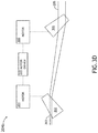
- FIG. 3D illustrates a block diagram view of a beam steering assembly, in accordance with one or more embodiments of the present disclosure.
- FIG. 3E illustrates a block diagram view of a beam steering assembly, in accordance with one or more embodiments of the present disclosure.
- FIG. 4 illustrates a block diagram view of a beam steering assembly, in accordance with one or more embodiments of the present disclosure.
- FIG. 5 illustrates a block diagram view of a beam steering assembly, in accordance with one or more embodiments of the present disclosure.
- FIG. 6A illustrates a block diagram view of a beam monitoring assembly, in accordance with one or more embodiments of the present disclosure.
- FIG. 6B illustrates a block diagram view of a beam monitoring assembly, in accordance with one or more embodiments of the present disclosure.
- FIG. 6C illustrates a block diagram view of a beam monitoring assembly, in accordance with one or more embodiments of the present disclosure.
- FIG. 7 illustrates a flow diagram depicting a method to compensate for illumination beam misalignment, in accordance with one or more embodiments of the present disclosure.
- FIGS. 1A through 7 a system and a method to compensate for illumination beam misalignment are disclosed, in accordance with one or more embodiments of the present disclosure.
- inspection systems implement an illumination beam focused at the Gaussian beam focal plane. Being focused at the focal plane, these inspection systems observe only a minimal impact of the illumination beam position from translational jitter in the inspection system.
- FIG. 1A illustrates a graph 100 of relative intensity versus beam position (in ⁇ m) for a Gaussian illumination beam profile, with data 102 and a fit curve 104 .
- FIG. 1B illustrates a graph 110 of relative intensity versus beam position (in ⁇ m) for a flat-top illumination beam profile, with data 112 .
- FIG. 1C illustrates a graph 120 of relative intensity versus beam position (in mm) for a modeled flat-top illumination beam profile generated by a beam modulator from an Gaussian illumination beam offset by ⁇ 0.1 mm, with data 122 , a fit curve 124 , and a comparison curve 126 .
- FIG. 1C illustrates a graph 120 of relative intensity versus beam position (in mm) for a modeled flat-top illumination beam profile generated by a beam modulator from an Gaussian illumination beam offset by ⁇ 0.1 mm, with data 122 , a fit curve 124 , and a comparison curve 126 .
- 1D illustrates a graph 130 of relative intensity versus beam position (in mm) for a modeled flat-top illumination beam profile generated by a beam modulator from an Gaussian illumination beam offset by +0.1 mm, with data 132 , a fit curve 134 , and a comparison curve 136 .
- FIG. 1E illustrates a graph 140 of relative intensity versus beam position for multiple modeled flat-top illumination beam profiles generated by a beam modulator from multiple offset Gaussian illumination beams.
- data 142 a and a fit curve 142 b illustrate a beam offset of ⁇ 150 ⁇ m.
- data 144 a and a fit curve 144 b illustrate a beam offset of ⁇ 300 ⁇ m.
- data 146 a and a fit curve 146 b illustrate a beam offset of ⁇ 50 ⁇ m.
- data 148 a and a fit curve 148 b illustrate a beam offset of 150 ⁇ m.
- data 150 a and a fit curve 150 b illustrate a beam offset of 300 ⁇ m.
- data 152 a and a fit curve 152 b illustrate a beam offset of 50 ⁇ m.
- FIG. 1F illustrates a graph 160 of jitter (in ⁇ m) measured as a function of time (in sec) within an inspection system, with data 162 .
- FIG. 1G illustrates a graph 170 of the relative amplitude of jitter versus the frequency of jitter (in Hz) within an inspection system, with data 172 .
- Embodiments of the present disclosure are directed to a system and a method to compensate for illumination beam misalignment.
- Embodiments of the present disclosure are also directed to measuring one or more of the following: a translational component of the position of an illumination beam, a pointing component of the position of the illumination beam, an illumination beam size, and/or illumination beam breathing data.
- Embodiments of the present disclosure are also directed to determining one or more illumination beam adjustments based on measured data.
- Embodiments of the present disclosure are also directed to forming a corrected illumination beam by adjusting one or more of the following: a translation component of a position of the illumination beam, a pointing component a position of the illumination beam, a drift in the size of the illumination beam, and/or a variance in the illumination beam breathing data.
- Embodiments of the present disclosure are also directed to measuring the illumination beam, determining adjustments for the illumination beam, and adjusting an illumination beam to form the corrected beam in one or more of an x-direction and/or a y
- FIG. 2 illustrates a block diagram view of a system 200 to compensate for illumination beam misalignment, in accordance with one or more embodiments of the present disclosure.
- the system 200 includes an illumination source 202 .
- the system 200 includes a beam steering assembly 204 .
- the system 200 includes a beam monitoring assembly 206 .
- the system 200 includes a controller 210 .
- the system 200 includes one or more motor drivers 220 .
- the system 200 includes a beam modulator 230 .
- the illumination source 202 may include any illumination source known in the art including, but not limited to, a broadband light source or a narrowband light source.
- the illumination source 202 includes one or more lasers.
- the illumination source 202 may include any laser or laser system known in the art capable of emitting radiation in the infrared, visible and/or ultraviolet portions of the electromagnetic spectrum.
- the illumination source 202 may include, but is not limited to, one or more diode lasers, one or more continuous wave (CW) lasers, one or more ion lasers, and the like.
- CW continuous wave
- the beam steering assembly 204 adjusts the incident beam 203 to form a corrected beam 205 .
- the beam monitoring assembly 206 is optically coupled to the beam steering assembly 204 .
- the beam steering assembly 204 directs the corrected beam 205 to the beam monitoring assembly 206 .
- the beam steering assembly 204 may direct the corrected beam 205 to the beam monitoring assembly 206 through an optical element assembly 250 .
- the optical element assembly 250 may include one or more optical elements known in the optical arts such as, but not limited to, steering optics, mirrors, beam splitters, lenses, collecting apertures, filters, and the like.
- the beam steering assembly 204 is communicatively coupled to one or more of the controller 210 and the one or more motor drivers 220 .
- the beam monitoring assembly 206 directs at least a portion of the corrected beam 205 to the beam modulator 230 .
- the beam modulator 230 may include, but is not limited to, a beam shaping optical element.
- the beam shaping optical element may include, but is not limited to, a multi-curved lens or a diffractive optical element.
- the beam monitoring assembly 206 may direct the corrected beam 205 to the beam modulator 230 through an optical element assembly 260 .
- the optical element assembly 260 may include one or more optical elements known in the optical arts such as, but not limited to, steering optics, mirrors, beam splitters, lenses, collecting apertures, filters, and the like.
- the beam monitoring assembly 206 is communicatively coupled to the controller 210 .
- the beam monitoring assembly 206 generates one or more sets of monitoring data for the corrected beam 205 .
- the one or more sets of monitoring data are generated via one or more beam monitoring sensors.
- the one or more beam monitoring sensors may include, but are not limited to, one or more cameras or one or more bi-cell detectors, described in detail further herein.
- the one or more sets of monitoring data include one or more offset parameters of the corrected beam 205 .
- the one or more offset parameters may include, but are not limited to, an offset pointing component of an offset position of the corrected beam 205 .
- the one or more offset parameters may include, but are not limited to, an offset translation component of the offset position of the corrected beam 205 .
- the one or more offset parameters may include, but are not limited to, an offset beam size.
- the one or more offset parameters may include, but are not limited to, offset beam breathing data.
- the one or more offset parameters of the corrected beam 205 includes one or more of an x-direction component and/or a y-direction component.
- the beam monitoring assembly 206 transmits the one or more sets of monitoring data for the corrected beam 205 to the controller 210 .
- the one or more motor drivers 220 are communicatively coupled to one or more of the beam steering assembly 204 and the controller 210 . In another embodiment, the one or more motor drivers 220 actuate one or more motors in the beam steering assembly 204 based on one or more beam position adjustments received from the controller 210 , as described in detail further herein.
- the beam steering assembly 204 includes one or more encoders.
- the encoders generate data following actuation of the one or more motors.
- the beam steering assembly 204 aggregates the generated encoder data prior to transmission to the controller 210 , and the controller 210 de-aggregates the aggregated encoder data upon receipt.
- the system 200 receives the generated encoder data in a non-aggregated form.
- the controller 210 includes one or more processors 212 and a memory medium 214 .
- one or more sets of program instructions 216 are stored in memory medium 214 .
- the one or more processors 212 are configured to execute the sets of program instructions 216 to carry out one or more of the various steps described throughout the present disclosure.
- the controller 210 is communicatively coupled to one or more of the beam steering assembly 204 , the beam monitoring assembly 206 , and the one or more motor drivers 220 .
- the controller 210 is configured to receive and/or acquire data or information from other systems or assemblies (e.g., the one or more sets of monitoring data from the beam monitoring assembly 206 , one or more sets of encoder data from the beam steering assembly 204 , or one or more user inputs received via a user interface) by a transmission medium that may include wireline and/or wireless portions.
- the controller 210 of the system 200 is configured to transmit data or information (e.g., the output of one or more procedures disclosed herein) to one or more systems or assemblies (e.g., one or more commands to the one or more motor drivers 220 , the beam steering assembly 204 , the beam monitoring assembly 206 , or a user interface) by a transmission medium that may include wireline and/or wireless portions.
- the transmission medium may serve as a data link between the controller 210 and other assemblies of the system 200 .
- the controller 210 is configured to send data to external systems via a transmission medium (e.g., network connection).
- the set of program instructions 216 are programmed to cause the one or more processors 212 to store one or more zero parameters for the corrected beam 206 .
- the one or more zero parameters may include, but are not limited to, a zero pointing component of a zero position of the corrected beam 205 .
- the one or more zero parameters may include, but are not limited to, a zero translation component of the zero position of the corrected beam 205 .
- the one or more zero parameters may include, but are not limited to, a zero beam size.
- the one or more zero parameters may include, but are not limited to, zero beam breathing data.
- the one or more zero parameters of the corrected beam 205 include one or more of an x-direction component and/or a y-direction component.
- the set of program instructions 216 are programmed to cause the one or more processors 212 to receive the one or more sets of monitoring data from the beam monitoring assembly 206 .
- the controller 210 calculates one or more differences between the one or more zero parameters and the one or more offset parameters of the corrected beam 205 .
- calculating the one or more differences may include calculating a pointing difference between the zero pointing component of the zero position of the corrected beam 205 and the offset pointing component of the offset position of the corrected beam 205 .
- calculating one or more differences may include calculating a translation difference between the zero translation component of the zero position of the corrected beam 205 and the offset translation component of the offset position of the corrected beam 205 .
- calculating one or more differences may include calculating a beam size difference between the zero beam size and the offset beam size.
- calculating one or more differences may include calculating a beam breathing data difference between the zero beam breathing data and the offset beam breathing data.
- the set of program instructions 216 are programmed to cause the one or more processors 212 to determine one or more beam position adjustments of the incident beam 203 based on the calculated one or more differences between the one or more zero parameters and the one or more offset parameters of the corrected beam 205 .
- the controller 210 transmits the one or more beam position adjustments to the one or more motor drivers 220 .
- the set of program instructions 216 are programmed to cause the one or more processors 212 to direct the beam steering assembly 204 , via the one or more motor drivers 220 , to actuate one or more motors and adjust the incident beam 203 to form the corrected beam 205 .
- the one or more motors drivers 220 may adjust the incident beam 203 based on the one or more beam position adjustments.
- the one or more beam position adjustments may include one or more commands to actuate the one or more motors coupled to one or more optical components of the beam steering assembly 204 , described in detail further herein.
- the set of program instructions 216 are programmed to cause the one or more processors 212 to verify the actuation of the one or more motors based on generated encoder data received from the beam steering assembly 204 .
- the one or more processors 212 of controller 210 include any one or more processing elements known in the art.
- the one or more processors 212 may include any microprocessor device configured to execute algorithms and/or instructions.
- the one or more processors 212 may consist of a desktop computer, mainframe computer system, workstation, image computer, parallel processor, vehicle on-board computer, handheld computer (e.g. tablet, smartphone, or phablet), or other computer system (e.g., networked computer) configured to execute a program configured to operate the system 200 , as described throughout the present disclosure. It should be recognized that the steps described throughout the present disclosure may be carried out by a single computer system or, alternatively, multiple computer systems.
- processor may be broadly defined to encompass any device having one or more processing elements, which execute the program instructions 216 from a non-transitory memory medium (e.g., memory 214 ).
- a non-transitory memory medium e.g., memory 214
- different assemblies of the system 200 e.g., the beam steering assembly 204 , the beam monitoring assembly 206 , the one or more motor drivers 220 , or a user interface
- the memory medium 214 of controller 210 includes any memory medium known in the art suitable for storing the program instructions 216 executable by the associated one or more processors 212 .
- the memory medium 214 may include a non-transitory memory medium.
- the memory medium 214 may include, but is not limited to, a read-only memory, a random access memory, a magnetic or optical memory device (e.g., disk), a magnetic tape, a solid state drive and the like.
- the memory 214 is configured to provide display information to a display device and/or the output of the various steps described herein. It is further noted that memory 214 may be housed in a common controller housing with the one or more processors 212 .
- the memory 214 may be located remotely with respect to the physical location of the processors 212 and controller 210 .
- the one or more processors 212 of controller 210 may access a remote memory (e.g., server), accessible through a network (e.g., internet, intranet and the like).
- the memory medium 214 stores the program instructions 216 for causing the one or more processors 212 to carry out the various steps described through the present disclosure.
- the system 200 includes a user interface.
- the user interface is communicatively coupled to the one or more processors 212 of controller 210 .
- the user interface includes a display device (e.g., a liquid crystal display (LCD), an organic light emitted diode (OLED) display, a cathode-ray tube (CRT) display, and the like).
- the user interface includes a user input device (e.g., a keyboard, a mouse, a touch screen, and the like).
- the system 200 may include a stage configured to secure a sample.
- an illumination beam generated by the beam modulator 230 illuminates the sample secured on the stage.
- the sample includes a wafer.
- the sample may include, but is not limited to, a semiconductor wafer.
- the term “wafer” refers to a substrate formed of a semiconductor and/or non-semi-conductor material.
- a semiconductor or semiconductor material may include, but are not limited to, monocrystalline silicon, gallium arsenide, and indium phosphide.
- the sample stage may include any appropriate mechanical and/or robotic assembly known in the art.
- the controller 210 (or another controller in the system 200 ) may actuate the sample stage.
- the sample stage may be configured by the controller 210 (or another controller in the system 200 ) to actuate the sample to a selected position or orientation.
- the sample stage may include or may be mechanically coupled to one or more actuators including, but not limited to, a motor or servo, where the one or more actuators are configured to translate or rotate the sample for positioning, focusing, and/or scanning in accordance with a selected inspection or metrology algorithm, several of which are known to the art.
- the system 200 may include one or more optical components configured to direct illumination reflected and/or scattered from the surface of the sample to one or more detectors.
- the detectors may include any appropriate detector known in the art.
- the detectors may include, but is not limited to, one or more photo-multiplier tubes (PMTs), charge coupled devices (CCDs), time delay integration (TDI) camera, and the like.
- the output of the detector may be communicatively coupled to the controller 210 .
- the detector may be coupled to the controller 210 in any suitable manner (e.g., by one or more transmission media indicated by the dotted line shown in FIG. 1 ) such that the controller 210 may receive the output generated by the detector.
- the controller 210 may be coupled to the multiple detectors as described above. It is noted herein the controller 210 may be configured to detect one or more defects of the sample using detection data collected and transmitted by the detector, utilizing any method and/or algorithm known in the art to detect defects on the wafer.
- the detector may be configured to accept instructions from another assembly of the system 200 including, but not limited to, controller 210 .
- the detector may include any detector configured to collect and analyze illumination reflected, scattered, diffracted, and/or radiated from a surface of the sample to locate one or more defects.
- a defect may be classified as a void, short, particle, residue, scum, or any other defect known in the art.
- the portion of the system 200 including the generation of monitoring data with the beam monitoring assembly 206 and the adjustment of the incident beam 203 to form the corrected beam 205 via the one or more motor drivers 220 , where the adjustments to the incident beam 203 are based on one or more beam adjustments determined by the controller 210 from the monitoring data is a closed compensation loop for purposes of the present disclosure.
- one or more external sources may act on the system 200 , such that the previously-described portion of the system 200 may instead be an open compensation loop. Therefore, the above description should not be interpreted as a limitation on the present disclosure but merely an illustration.
- the embodiments of the system 200 illustrated in FIG. 2 may be further configured as described herein.
- the system 200 may be configured to perform any other steps(s) of any of the system and method embodiment(s) described herein.
- FIGS. 3A-5 illustrate beam steering assemblies 204 a , 204 b , and 204 c , in accordance with one or more embodiments of the present disclosure. It is noted herein the embodiments and examples described throughout the present disclosure should be interpreted to extend to the beam steering assemblies 204 a , 204 b , and 204 c in FIGS. 3A-5 unless otherwise noted.
- FIGS. 3A-3E illustrate the beam steering assembly 204 a , in accordance with one or more embodiments of the present disclosure.
- the beam steering assembly 204 a includes a first prism 302 coupled to one or more motors 304 .
- the one or more motors 304 are coupled to one or more motor drivers 220 .
- the beam steering assembly 204 a includes a second prism 306 coupled to one or more motors 308 .
- the one or more motors 308 are coupled to one or more motor drivers 220 .
- FIGS. 3B-3E illustrate how translating and/or tilting one or more of the prism 302 or the prism 306 adjusts the incident beam 203 to form the corrected beam 205 .
- changing the distance between the prism 302 and the prism 306 adjusts the translation component of a position of the incident beam 203 to form the corrected beam 205 .
- tilting one or more of the prism 302 and the prism 306 adjusts the pointing component of the position of the incident beam 203 to form the corrected beam 205 .
- FIG. 3E illustrates the tilting of both the prism 302 and the prism 306 through prism positions (a), (b), and (c).
- a combination of changing the distance between the prism 302 and the prism 306 , and tilting one or more of the prism 302 and the prism 306 adjusts the size of the incident beam 203 to form the corrected beam 205 .
- linear motion of the prism 302 and/or the prism 306 is driven via one or more direct-drive motors 304 and/or 308 , respectively.
- rotational motion of the prism 302 and/or the prism 306 is driven via one or more stepper motors 304 and/or 308 operating in brushless mode, respectively. It is contemplated that the combination of one or more direct-drive motors for linear motion and one or more stepper motors operating in brushless mode for rotational motion is fast enough to actively adjust the incident beam 203 to form the corrected beam 205 via one or more of translation or rotation of one or more of the prisms 302 and 306 .
- the beam steering assembly 204 a is not limited to the two prisms 302 and 306 .
- the beam steering assembly 204 a may include may include up to an N number of prisms.
- the beam steering assembly 204 a may include one or more pairs of prisms per beam adjustment direction (i.e. at least four prisms to adjust the incident beam 203 in both the x-direction and the y-direction to form the corrected beam 205 , or at least two prisms to adjust the incident beam 203 in either the x-direction or the y-direction to form the corrected beam 205 ). Therefore, the above description should not be interpreted as a limitation on the present disclosure but merely an illustration.
- FIGS. 3A-3E Although a single motor driver 220 is illustrated in FIGS. 3A-3E as controlling the one or more motors 304 and the one or more motors 308 , it is noted herein that at least some of the one or more motors 304 and the one or more motors 308 may be controlled by a motor-specific motor driver 220 . Therefore, the above description should not be interpreted as a limitation on the present disclosure but merely an illustration.
- FIG. 4 illustrates the beam steering assembly 204 b , in accordance with one or more embodiments of the present disclosure.
- the beam steering assembly 204 b includes a reflecting mirror 402 coupled to one or more motors 404 .
- the one or more motors 404 may be a piezoelectric motor.
- the one or more motors 404 are coupled to the motor driver 220 . It is noted herein that where there are multiple motors 404 , at least some of the multiple motors 404 may be controlled by a motor-specific motor driver 220 .
- the reflecting mirror 402 at position (a) will reflect the incident beam 203 to the beam monitoring assembly 206 without adjusting the incident beam 203 .
- moving the reflecting mirror 402 from position (a) to position (b) adjusts the pointing component of the position of the incident beam 203 to form the corrected beam 205 in one or more of the x-direction and/or the y-direction. It is noted, however, that moving the reflecting mirror 402 from position (a) to position (b) will not adjust the translation component of the position of the incident beam 203 to form the corrected beam 205 .
- FIG. 5 illustrates the beam steering assembly 204 c , in accordance with one or more embodiments of the present disclosure.
- the beam steering assembly 204 c includes a rectangular prism 502 coupled to one or more motors 504 .
- the one or more motors 404 may be a servo motor.
- the one or more motors 404 are coupled to the motor driver 220 . It is noted herein that where there are multiple motors 504 , at least some of the multiple motors 504 may be controlled by a motor-specific motor driver 220 .
- the prism 502 at position (a) will direct the incident beam 203 to the beam monitoring assembly 206 without adjusting the incident beam 203 .
- rotating the prism 502 from position (a) to position (b) adjusts the translation component of the position of the incident beam 203 to form the corrected beam 205 in one or more of the x-direction and/or the y-direction. It is noted, however, that rotating the prism 502 from position (a) to position (b) will not adjust the pointing component of the position of the incident beam 203 to form the corrected beam 205 .
- beam steering assemblies 204 a , 204 b , and 204 c are not limited to the previously-disclosed types of motors 304 , 308 , 404 , or 504 .
- motors 304 , 308 , 404 , or 504 may be any of a direct-drive motor, a direct drive motor, a stepper motor, a stepper motor operating in brushless mode, a piezoelectric motor, a servo motor, or any other motor known in the art. Therefore, the above description should not be interpreted as a limitation on the present disclosure but merely an illustration.
- FIGS. 6A-6C illustrate beam monitoring assemblies 206 a , 206 b , and 206 c , in accordance with one or more embodiments of the present disclosure. It is noted herein the embodiments and examples described throughout the present disclosure should be interpreted to extend to the beam monitoring assemblies 206 a , 206 b , and 206 c in FIGS. 6A-6C unless otherwise noted.
- beam monitoring assemblies 206 a , 206 b , and 206 c receive the corrected beam 205 .
- beam monitoring assemblies 206 a , 206 b , and 206 c include a leak mirror 602 .
- the leak mirror 602 reflects at least a portion of the corrected beam 205 to the beam modulator 230 .
- the leak mirror 602 directs at least a portion of the corrected beam 205 to a beam splitter 604 .
- the beam splitter 604 directs at least a portion of the corrected beam 205 directed by the leak mirror 602 to a first imaging device 610 through at least one optical element 606 .
- the at least one optical element 606 may include, but is not limited to, a telescope beam expander.
- the telescope beam expander 606 may increase the size, while maintaining beam collimation, of the splitter-directed portion of the corrected beam 205 .
- the at least one optical element 606 may be any optical element known in the art.
- the beam splitter 604 reflects at least a portion of the corrected beam 205 directed by the leak mirror 602 to a second imaging device 612 through at least one optical element 608 .
- the at least one optical element 608 may include, but is not limited to, a focusing lens.
- the imaging device 612 will be on the focal plane of the focusing lens.
- the at least one optical element 608 may be any optical element known in the art.
- the ratio of the corrected beam 205 directed to the first imaging device 610 versus than the portion of the corrected beam 205 reflected to the second imaging device 612 may be 50/50.
- the beam splitter 604 may reflect/direct the corrected beam 205 in any ratio. Therefore, the above description should not be interpreted as a limitation on the present disclosure but merely an illustration.
- imaging devices 610 and 612 are cameras capable of measuring one or more of illumination beam translational jitter, illumination beam pointing jitter, illumination beam size, and illumination beam breathing data in both the x-direction and the y-direction (i.e. are two-dimensional cameras).
- the cameras 610 and 612 monitor one or more of translational jitter and pointing jitter of the corrected beam 205 as a function of time.
- camera 610 may measure translational jitter, pointing jitter, and beam size in both the x-direction and the y-direction.
- camera 612 may measure the pointing jitter in both the x-direction and the y-direction.
- the measurements taken by the cameras 610 and 612 may be processed via digital signal processor (DSP) code.
- DSP digital signal processor
- a centroid position fitting of an illumination beam measured by the cameras 610 and 612 may be determined via DSP code.
- the decoupling of translational jitter and pointing jitter in the measurements taken by the cameras 610 and 612 may be done in real time via DSP code.
- the beam monitoring assemblies 206 a , 206 b , and 206 c may include a mixed number of cameras and bi-cell detectors. Therefore, the above description should not be interpreted as a limitation on the present disclosure but merely an illustration.
- Advantages of embodiments of the present disclosure include compensating for illumination beam misalignment in one or more of an x-direction and/or a y-direction. Advantages of embodiments of the present disclosure also include measuring one or more of the following: a translational component of the position of an illumination beam, a pointing component of the position of the illumination beam, an illumination beam size, and illumination beam breathing data. Advantages of embodiments of the present disclosure also include forming a corrected beam from the illumination beam by adjusting one or more of the following: the translational component of the position of the illumination beam, the pointing component of the position of the illumination beam, and drifts in the size of the illumination beam.
- system 200 may be configured with at least a third set of capabilities which operate in one or more of an x-direction and/or a y-direction.
- the at least a third set of capabilities includes one or more of the first set of capabilities and/or the second set of capabilities.
- FIG. 7 illustrates a process flow diagram depicting a method 700 to compensate for illumination beam misalignment.
- the method may also include any other step(s) that can be performed by the output acquisition subsystem and/or computer subsystem(s) or system(s) described herein.
- the steps may be performed by one or more computer systems, which may be configured according to any of the embodiments described herein. It is noted herein that the steps of method 700 may be implemented all or in part by the system 200 . It is recognized, however, that the method 700 is not limited to the system 200 in that additional or alternative system-level embodiments may carry out all or part of the steps of method 700 .
- an incident beam 203 is adjusted to form a corrected beam 205 .
- the incident beam 203 is received by the beam steering assembly 204 from the illumination source 202 .
- the beam steering assembly 204 adjusts the incident beam 203 to form the corrected beam 205 .
- the system 200 may implement any of the beam steering assemblies 204 a , 204 b , or 204 c to adjust the incident beam 203 to form the corrected beam 205 .
- the corrected beam 205 is directed by the beam steering assembly 204 to the beam monitoring assembly 206 .
- monitoring data is generated.
- the monitoring data is generated by the beam monitoring assembly 206 .
- the system 200 may implement any of the beam monitoring assemblies 206 a , 206 b , or 206 c to generate the monitoring data.
- the monitoring data includes one or more offset parameters of the corrected beam 205 .
- the one or more sets of monitoring data include one or more offset parameters of the corrected beam 205 .
- the one or more offset parameters may include, but are not limited to, an offset pointing component of the offset position of the corrected beam 205 .
- the one or more offset parameters may include, but are not limited to, an offset translation component of the offset position of the corrected beam 205 .
- the one or more offset parameters may include, but are not limited to, an offset beam size.
- the one or more offset parameters may include, but are not limited to, offset beam breathing data.
- the one or more offset parameters of the corrected beam 205 include one or more of an x-direction component and/or a y-direction component.
- the beam monitoring assembly 206 transmits the one or more sets of monitoring data for the corrected beam 205 to the controller 210 .
- one or more zero parameters of the corrected beam 205 are stored.
- the one or more zero parameters are stored by the controller 210 .
- the one or more zero parameters may include, but are not limited to, a zero pointing component of the zero position of the corrected beam 205 .
- the zero parameters may include a zero translation component of the zero position of the corrected beam 205 .
- the one or more zero parameters may include, but are not limited to, a zero beam size.
- the one or more zero parameters may include, but are not limited to, zero beam breathing data.
- the one or more zero parameters of the corrected beam 205 include one or more of an x-direction component and/or a y-direction component.
- calculating one or more differences may include calculating a translation difference between the zero translation component of the zero position of the corrected beam 205 and the offset translation component of the offset position of the corrected beam 205 .
- calculating one or more differences may include calculating a beam size difference between the zero beam size and the offset beam size.
- calculating one or more differences may include calculating a beam breathing data difference between the zero beam breathing data and the offset beam breathing data.
- a beam steering assembly is directed to adjust the incident beam 203 to form the corrected beam 205 .
- the beam steering assembly 204 includes one or more motors coupled to one or more optical components.
- the one or more motors are actuated by the one or more motor drivers 220 .
- the one or more beam positions adjustments are received by the one or more motor drivers 220 .
- the one or more beam adjustments may include one or more commands to actuate the one or more motors of the beam steering assembly 204 . For instance, actuating the one or more motors moves the one or more optical components, which adjusts the incident beam 203 to form the corrected beam 205 .
- encoder data for the one or more motors following actuation of the one or more motors is generated.
- the beam steering assembly 204 includes one or more encoders.
- the actuation of the one or more motors via the one or more motor drivers 220 based on the one or more beam position adjustments is recorded by the one or more encoders as the encoder data.
- the encoder data is transmitted to the controller 210 .
- All of the methods described herein may include storing results of one or more steps of the method embodiments in a memory medium.
- the results may include any of the results described herein and may be stored in any manner known in the art.
- the memory medium may include any memory medium described herein or any other suitable memory medium known in the art.
- the results can be accessed in the memory medium and used by any of the method or system embodiments described herein, formatted for display to a user, used by another software module, method, or system, etc.
- the results may be stored “permanently,” “semi-permanently,” temporarily, or for some period of time.
- the memory medium may be random access memory (RAM), and the results may not necessarily persist indefinitely in the memory medium.
- a typical data processing system generally includes one or more of a system unit housing, a display device, a memory such as volatile and non-volatile memory, processors such as microprocessors and digital signal processors, computational entities such as operating systems, drivers, graphical user interfaces, and applications programs, one or more interaction devices, such as a touch pad or screen, and/or control systems including feedback loops and control motors (e.g., feedback for sensing position and/or velocity; control motors for moving and/or adjusting components and/or quantities).
- a typical data processing system may be implemented utilizing any suitable commercially available components, such as those typically found in data computing/communication and/or network computing/communication systems.
Landscapes
- Engineering & Computer Science (AREA)
- Physics & Mathematics (AREA)
- General Physics & Mathematics (AREA)
- Manufacturing & Machinery (AREA)
- Analytical Chemistry (AREA)
- Chemical & Material Sciences (AREA)
- Life Sciences & Earth Sciences (AREA)
- Biochemistry (AREA)
- General Health & Medical Sciences (AREA)
- Immunology (AREA)
- Pathology (AREA)
- Health & Medical Sciences (AREA)
- Computer Hardware Design (AREA)
- Microelectronics & Electronic Packaging (AREA)
- Power Engineering (AREA)
- Optics & Photonics (AREA)
- Condensed Matter Physics & Semiconductors (AREA)
- Length Measuring Devices By Optical Means (AREA)
- Testing Or Measuring Of Semiconductors Or The Like (AREA)
- Investigating Materials By The Use Of Optical Means Adapted For Particular Applications (AREA)
- Mounting And Adjusting Of Optical Elements (AREA)
- Mechanical Light Control Or Optical Switches (AREA)
- Slot Machines And Peripheral Devices (AREA)
- Exposure And Positioning Against Photoresist Photosensitive Materials (AREA)
Priority Applications (9)
| Application Number | Priority Date | Filing Date | Title |
|---|---|---|---|
| US15/477,885 US10495579B2 (en) | 2016-05-02 | 2017-04-03 | System and method for compensation of illumination beam misalignment |
| PCT/US2017/030258 WO2017192403A1 (en) | 2016-05-02 | 2017-04-28 | System and method for compensation of illumination beam misalignment |
| CN201780027202.7A CN109075099B (zh) | 2016-05-02 | 2017-04-28 | 用于照明光束未对准的补偿的系统及方法 |
| SG11201806925PA SG11201806925PA (en) | 2016-05-02 | 2017-04-28 | System and method for compensation of illumination beam misalignment |
| DE112017002293.2T DE112017002293B4 (de) | 2016-05-02 | 2017-04-28 | System und Verfahren zur Kompensation von Fehlausrichtungen von Beleuchtungsstrahlung |
| KR1020187033743A KR102190345B1 (ko) | 2016-05-02 | 2017-04-28 | 조명 빔 오정렬의 보정을 위한 시스템 및 방법 |
| JP2018557327A JP6741787B2 (ja) | 2016-05-02 | 2017-04-28 | 照明ビームの位置ずれの補償のためのシステムおよび方法 |
| TW106114548A TWI728104B (zh) | 2016-05-02 | 2017-05-02 | 用於照明光束未對準之補償之系統及方法 |
| IL262231A IL262231B (en) | 2016-05-02 | 2018-10-09 | System and method for compensating misalignment of an illumination beam |
Applications Claiming Priority (2)
| Application Number | Priority Date | Filing Date | Title |
|---|---|---|---|
| US201662330756P | 2016-05-02 | 2016-05-02 | |
| US15/477,885 US10495579B2 (en) | 2016-05-02 | 2017-04-03 | System and method for compensation of illumination beam misalignment |
Publications (2)
| Publication Number | Publication Date |
|---|---|
| US20170336329A1 US20170336329A1 (en) | 2017-11-23 |
| US10495579B2 true US10495579B2 (en) | 2019-12-03 |
Family
ID=60203214
Family Applications (1)
| Application Number | Title | Priority Date | Filing Date |
|---|---|---|---|
| US15/477,885 Active 2037-08-14 US10495579B2 (en) | 2016-05-02 | 2017-04-03 | System and method for compensation of illumination beam misalignment |
Country Status (9)
| Country | Link |
|---|---|
| US (1) | US10495579B2 (enExample) |
| JP (1) | JP6741787B2 (enExample) |
| KR (1) | KR102190345B1 (enExample) |
| CN (1) | CN109075099B (enExample) |
| DE (1) | DE112017002293B4 (enExample) |
| IL (1) | IL262231B (enExample) |
| SG (1) | SG11201806925PA (enExample) |
| TW (1) | TWI728104B (enExample) |
| WO (1) | WO2017192403A1 (enExample) |
Families Citing this family (3)
| Publication number | Priority date | Publication date | Assignee | Title |
|---|---|---|---|---|
| US10365211B2 (en) * | 2017-09-26 | 2019-07-30 | Kla-Tencor Corporation | Systems and methods for metrology beam stabilization |
| DE102020209268B3 (de) | 2020-07-22 | 2021-10-14 | Hochschule Emden/Leer | Optisches System |
| CN117110311B (zh) * | 2022-05-17 | 2025-09-12 | 深圳中科飞测科技股份有限公司 | 一种光学检测系统及图像动态对准方法 |
Citations (14)
| Publication number | Priority date | Publication date | Assignee | Title |
|---|---|---|---|---|
| US4696047A (en) | 1985-02-28 | 1987-09-22 | Texas Instruments Incorporated | Apparatus for automatically inspecting electrical connecting pins |
| JP2001334376A (ja) | 2000-05-26 | 2001-12-04 | Nec Toyama Ltd | レーザ加工装置及びレーザ光スポット位置補正方法 |
| JP2003179142A (ja) | 2001-12-10 | 2003-06-27 | Nec Microsystems Ltd | ジッタ検査回路を搭載した半導体装置およびそのジッタ検査方法 |
| US20040109487A1 (en) | 2002-12-06 | 2004-06-10 | Zhang Guangzhi G. | External cavity laser with dispersion compensation for mode-hop-free tuning |
| US6831736B2 (en) | 2002-10-07 | 2004-12-14 | Applied Materials Israel, Ltd. | Method of and apparatus for line alignment to compensate for static and dynamic inaccuracies in scanning |
| US20060202115A1 (en) * | 2005-03-10 | 2006-09-14 | Hitachi Via Mechanics, Ltd. | Apparatus and method for beam drift compensation |
| US7149234B2 (en) | 1998-07-18 | 2006-12-12 | Cymer, Inc. | High repetition rate gas discharge laser with precise pulse timing control |
| US7307711B2 (en) * | 2004-10-29 | 2007-12-11 | Hitachi Via Mechanics (Usa), Inc. | Fluorescence based laser alignment and testing of complex beam delivery systems and lenses |
| KR20080014385A (ko) | 2006-08-11 | 2008-02-14 | 동부일렉트로닉스 주식회사 | 레이저 빔 위치 자동 조정 장치 및 이를 이용한 레이저 빔위치 자동 조정 방법 |
| KR20110050821A (ko) | 2009-11-09 | 2011-05-17 | 삼성전자주식회사 | 지터를 감소시킬 수 있는 dll회로 및 이를 포함하는 반도체 장치 |
| US8379204B1 (en) | 2007-08-17 | 2013-02-19 | Gsi Group Corporation | System and method for automatic laser beam alignment |
| US20130151185A1 (en) | 2010-08-20 | 2013-06-13 | Fujitsu Limited | Semiconductor device |
| US8885146B2 (en) | 2008-02-26 | 2014-11-11 | 3M Innovative Properties Company | Multi-photon exposure system |
| US20150170357A1 (en) | 2013-03-15 | 2015-06-18 | Kla-Tencor Corporation | Image synchronization of scanning wafer inspection system |
Family Cites Families (5)
| Publication number | Priority date | Publication date | Assignee | Title |
|---|---|---|---|---|
| JPS60221720A (ja) * | 1984-04-18 | 1985-11-06 | Fuji Photo Film Co Ltd | 光ビ−ム走査装置 |
| JP4908925B2 (ja) * | 2006-02-08 | 2012-04-04 | 株式会社日立ハイテクノロジーズ | ウェハ表面欠陥検査装置およびその方法 |
| JP5331586B2 (ja) * | 2009-06-18 | 2013-10-30 | 株式会社日立ハイテクノロジーズ | 欠陥検査装置および検査方法 |
| US9068952B2 (en) * | 2009-09-02 | 2015-06-30 | Kla-Tencor Corporation | Method and apparatus for producing and measuring dynamically focussed, steered, and shaped oblique laser illumination for spinning wafer inspection system |
| JP5134603B2 (ja) * | 2009-09-09 | 2013-01-30 | 株式会社日立ハイテクノロジーズ | 光ビーム調整方法及び光ビーム調整装置 |
-
2017
- 2017-04-03 US US15/477,885 patent/US10495579B2/en active Active
- 2017-04-28 JP JP2018557327A patent/JP6741787B2/ja active Active
- 2017-04-28 CN CN201780027202.7A patent/CN109075099B/zh active Active
- 2017-04-28 KR KR1020187033743A patent/KR102190345B1/ko active Active
- 2017-04-28 SG SG11201806925PA patent/SG11201806925PA/en unknown
- 2017-04-28 WO PCT/US2017/030258 patent/WO2017192403A1/en not_active Ceased
- 2017-04-28 DE DE112017002293.2T patent/DE112017002293B4/de active Active
- 2017-05-02 TW TW106114548A patent/TWI728104B/zh active
-
2018
- 2018-10-09 IL IL262231A patent/IL262231B/en active IP Right Grant
Patent Citations (14)
| Publication number | Priority date | Publication date | Assignee | Title |
|---|---|---|---|---|
| US4696047A (en) | 1985-02-28 | 1987-09-22 | Texas Instruments Incorporated | Apparatus for automatically inspecting electrical connecting pins |
| US7149234B2 (en) | 1998-07-18 | 2006-12-12 | Cymer, Inc. | High repetition rate gas discharge laser with precise pulse timing control |
| JP2001334376A (ja) | 2000-05-26 | 2001-12-04 | Nec Toyama Ltd | レーザ加工装置及びレーザ光スポット位置補正方法 |
| JP2003179142A (ja) | 2001-12-10 | 2003-06-27 | Nec Microsystems Ltd | ジッタ検査回路を搭載した半導体装置およびそのジッタ検査方法 |
| US6831736B2 (en) | 2002-10-07 | 2004-12-14 | Applied Materials Israel, Ltd. | Method of and apparatus for line alignment to compensate for static and dynamic inaccuracies in scanning |
| US20040109487A1 (en) | 2002-12-06 | 2004-06-10 | Zhang Guangzhi G. | External cavity laser with dispersion compensation for mode-hop-free tuning |
| US7307711B2 (en) * | 2004-10-29 | 2007-12-11 | Hitachi Via Mechanics (Usa), Inc. | Fluorescence based laser alignment and testing of complex beam delivery systems and lenses |
| US20060202115A1 (en) * | 2005-03-10 | 2006-09-14 | Hitachi Via Mechanics, Ltd. | Apparatus and method for beam drift compensation |
| KR20080014385A (ko) | 2006-08-11 | 2008-02-14 | 동부일렉트로닉스 주식회사 | 레이저 빔 위치 자동 조정 장치 및 이를 이용한 레이저 빔위치 자동 조정 방법 |
| US8379204B1 (en) | 2007-08-17 | 2013-02-19 | Gsi Group Corporation | System and method for automatic laser beam alignment |
| US8885146B2 (en) | 2008-02-26 | 2014-11-11 | 3M Innovative Properties Company | Multi-photon exposure system |
| KR20110050821A (ko) | 2009-11-09 | 2011-05-17 | 삼성전자주식회사 | 지터를 감소시킬 수 있는 dll회로 및 이를 포함하는 반도체 장치 |
| US20130151185A1 (en) | 2010-08-20 | 2013-06-13 | Fujitsu Limited | Semiconductor device |
| US20150170357A1 (en) | 2013-03-15 | 2015-06-18 | Kla-Tencor Corporation | Image synchronization of scanning wafer inspection system |
Non-Patent Citations (1)
| Title |
|---|
| ACS Motion Control, "Dual Axis EtherCAT NanoPWM Drive Module", Aug. 2015, 2 pages, Ver 3.0, www.acsmotioncontrol.com. |
Also Published As
| Publication number | Publication date |
|---|---|
| CN109075099B (zh) | 2023-07-14 |
| SG11201806925PA (en) | 2018-11-29 |
| US20170336329A1 (en) | 2017-11-23 |
| KR20180132923A (ko) | 2018-12-12 |
| DE112017002293B4 (de) | 2025-06-05 |
| IL262231B (en) | 2021-06-30 |
| DE112017002293T5 (de) | 2019-02-14 |
| WO2017192403A1 (en) | 2017-11-09 |
| TWI728104B (zh) | 2021-05-21 |
| CN109075099A (zh) | 2018-12-21 |
| TW201743048A (zh) | 2017-12-16 |
| KR102190345B1 (ko) | 2020-12-11 |
| JP6741787B2 (ja) | 2020-08-19 |
| JP2019523981A (ja) | 2019-08-29 |
| IL262231A (en) | 2018-11-29 |
Similar Documents
| Publication | Publication Date | Title |
|---|---|---|
| US6798498B2 (en) | Apparatus for evaluating polysilicon film | |
| CN116724225B (zh) | 用于计量的光瞳平面光束扫描 | |
| US6833918B2 (en) | Light scattering particle size distribution measuring apparatus and method of use | |
| US10495579B2 (en) | System and method for compensation of illumination beam misalignment | |
| EP3290982B1 (en) | Optical apparatus, machining apparatus, and article manufacturing method | |
| US20080192264A1 (en) | Device for Determining the Position of at Least One Structure on an Object, Use of an Illumination Apparatus with the Device and Use of Protective Gas with the Device | |
| JPWO2001083859A1 (ja) | メルトレベル検出装置及び検出方法 | |
| WO2022162881A1 (ja) | 欠陥検査装置 | |
| US11170971B2 (en) | Multiple working distance height sensor using multiple wavelengths | |
| US9146156B2 (en) | Light source tracking in optical metrology system | |
| US6179448B1 (en) | Automated light tuner | |
| EP4423456A1 (en) | Extra tall target metrology | |
| CN220490702U (zh) | 一种基于光散射技术的晶体体缺陷三维检测装置 | |
| CN106255911A (zh) | 自动聚焦系统 | |
| US20230305154A1 (en) | Laser tracking device | |
| CN118565774B (zh) | 改进型刀口测量红外光学传递函数测量系统的调测方法 | |
| TWI727393B (zh) | 雷射與攝像整合系統及其方法 | |
| TW202347906A (zh) | 雷射光的光軸調整方法及裝置 | |
| KR20230100034A (ko) | 광 정렬 틀어짐 현상 개선을 위한 자동 정렬 장치 | |
| KR20240117179A (ko) | 레이저 빔을 이용한 카메라 정렬 장치 및 그를 포함하는 검사 시스템 | |
| Aleksandrov et al. | Automatic adjustment system for the multipass eight-channel power module of a megajoule laser | |
| WO2025158581A1 (ja) | 光学検査装置及び光学検査方法 | |
| CN103091990B (zh) | 一种调焦调平系统中光斑水平位置调整机构及方法 | |
| CN114626182A (zh) | 线宽压窄模块温度监测装置及其监测方法 | |
| JPH01144553A (ja) | 電子線マイクロアナライザ |
Legal Events
| Date | Code | Title | Description |
|---|---|---|---|
| AS | Assignment |
Owner name: KLA-TENCOR CORPORATION, CALIFORNIA Free format text: ASSIGNMENT OF ASSIGNORS INTEREST;ASSIGNORS:LI, FRANK;XU, ZHIWEI;SWISHER, TIMOTHY;AND OTHERS;SIGNING DATES FROM 20170609 TO 20170623;REEL/FRAME:043003/0136 |
|
| STPP | Information on status: patent application and granting procedure in general |
Free format text: NON FINAL ACTION MAILED |
|
| STPP | Information on status: patent application and granting procedure in general |
Free format text: RESPONSE TO NON-FINAL OFFICE ACTION ENTERED AND FORWARDED TO EXAMINER |
|
| STPP | Information on status: patent application and granting procedure in general |
Free format text: NOTICE OF ALLOWANCE MAILED -- APPLICATION RECEIVED IN OFFICE OF PUBLICATIONS |
|
| STPP | Information on status: patent application and granting procedure in general |
Free format text: AWAITING TC RESP., ISSUE FEE NOT PAID |
|
| STPP | Information on status: patent application and granting procedure in general |
Free format text: NOTICE OF ALLOWANCE MAILED -- APPLICATION RECEIVED IN OFFICE OF PUBLICATIONS |
|
| STPP | Information on status: patent application and granting procedure in general |
Free format text: PUBLICATIONS -- ISSUE FEE PAYMENT VERIFIED |
|
| STCF | Information on status: patent grant |
Free format text: PATENTED CASE |
|
| MAFP | Maintenance fee payment |
Free format text: PAYMENT OF MAINTENANCE FEE, 4TH YEAR, LARGE ENTITY (ORIGINAL EVENT CODE: M1551); ENTITY STATUS OF PATENT OWNER: LARGE ENTITY Year of fee payment: 4 |