US10344729B2 - Engine including direct injector and port injector - Google Patents
Engine including direct injector and port injector Download PDFInfo
- Publication number
- US10344729B2 US10344729B2 US15/595,042 US201715595042A US10344729B2 US 10344729 B2 US10344729 B2 US 10344729B2 US 201715595042 A US201715595042 A US 201715595042A US 10344729 B2 US10344729 B2 US 10344729B2
- Authority
- US
- United States
- Prior art keywords
- port
- injector
- intake
- cylinder
- intake port
- Prior art date
- Legal status (The legal status is an assumption and is not a legal conclusion. Google has not performed a legal analysis and makes no representation as to the accuracy of the status listed.)
- Active
Links
Images


Classifications
-
- F—MECHANICAL ENGINEERING; LIGHTING; HEATING; WEAPONS; BLASTING
- F02—COMBUSTION ENGINES; HOT-GAS OR COMBUSTION-PRODUCT ENGINE PLANTS
- F02M—SUPPLYING COMBUSTION ENGINES IN GENERAL WITH COMBUSTIBLE MIXTURES OR CONSTITUENTS THEREOF
- F02M69/00—Low-pressure fuel-injection apparatus ; Apparatus with both continuous and intermittent injection; Apparatus injecting different types of fuel
- F02M69/04—Injectors peculiar thereto
- F02M69/042—Positioning of injectors with respect to engine, e.g. in the air intake conduit
-
- F—MECHANICAL ENGINEERING; LIGHTING; HEATING; WEAPONS; BLASTING
- F02—COMBUSTION ENGINES; HOT-GAS OR COMBUSTION-PRODUCT ENGINE PLANTS
- F02M—SUPPLYING COMBUSTION ENGINES IN GENERAL WITH COMBUSTIBLE MIXTURES OR CONSTITUENTS THEREOF
- F02M35/00—Combustion-air cleaners, air intakes, intake silencers, or induction systems specially adapted for, or arranged on, internal-combustion engines
- F02M35/10—Air intakes; Induction systems
- F02M35/10006—Air intakes; Induction systems characterised by the position of elements of the air intake system in direction of the air intake flow, i.e. between ambient air inlet and supply to the combustion chamber
- F02M35/10078—Connections of intake systems to the engine
- F02M35/10085—Connections of intake systems to the engine having a connecting piece, e.g. a flange, between the engine and the air intake being foreseen with a throttle valve, fuel injector, mixture ducts or the like
-
- F—MECHANICAL ENGINEERING; LIGHTING; HEATING; WEAPONS; BLASTING
- F02—COMBUSTION ENGINES; HOT-GAS OR COMBUSTION-PRODUCT ENGINE PLANTS
- F02M—SUPPLYING COMBUSTION ENGINES IN GENERAL WITH COMBUSTIBLE MIXTURES OR CONSTITUENTS THEREOF
- F02M35/00—Combustion-air cleaners, air intakes, intake silencers, or induction systems specially adapted for, or arranged on, internal-combustion engines
- F02M35/10—Air intakes; Induction systems
- F02M35/1015—Air intakes; Induction systems characterised by the engine type
- F02M35/10157—Supercharged engines
-
- F—MECHANICAL ENGINEERING; LIGHTING; HEATING; WEAPONS; BLASTING
- F02—COMBUSTION ENGINES; HOT-GAS OR COMBUSTION-PRODUCT ENGINE PLANTS
- F02M—SUPPLYING COMBUSTION ENGINES IN GENERAL WITH COMBUSTIBLE MIXTURES OR CONSTITUENTS THEREOF
- F02M35/00—Combustion-air cleaners, air intakes, intake silencers, or induction systems specially adapted for, or arranged on, internal-combustion engines
- F02M35/10—Air intakes; Induction systems
- F02M35/1015—Air intakes; Induction systems characterised by the engine type
- F02M35/10177—Engines having multiple fuel injectors or carburettors per cylinder
-
- F—MECHANICAL ENGINEERING; LIGHTING; HEATING; WEAPONS; BLASTING
- F02—COMBUSTION ENGINES; HOT-GAS OR COMBUSTION-PRODUCT ENGINE PLANTS
- F02M—SUPPLYING COMBUSTION ENGINES IN GENERAL WITH COMBUSTIBLE MIXTURES OR CONSTITUENTS THEREOF
- F02M35/00—Combustion-air cleaners, air intakes, intake silencers, or induction systems specially adapted for, or arranged on, internal-combustion engines
- F02M35/10—Air intakes; Induction systems
- F02M35/10209—Fluid connections to the air intake system; their arrangement of pipes, valves or the like
- F02M35/10216—Fuel injectors; Fuel pipes or rails; Fuel pumps or pressure regulators
-
- F—MECHANICAL ENGINEERING; LIGHTING; HEATING; WEAPONS; BLASTING
- F02—COMBUSTION ENGINES; HOT-GAS OR COMBUSTION-PRODUCT ENGINE PLANTS
- F02M—SUPPLYING COMBUSTION ENGINES IN GENERAL WITH COMBUSTIBLE MIXTURES OR CONSTITUENTS THEREOF
- F02M35/00—Combustion-air cleaners, air intakes, intake silencers, or induction systems specially adapted for, or arranged on, internal-combustion engines
- F02M35/10—Air intakes; Induction systems
- F02M35/104—Intake manifolds
- F02M35/116—Intake manifolds for engines with cylinders in V-arrangement or arranged oppositely relative to the main shaft
-
- F—MECHANICAL ENGINEERING; LIGHTING; HEATING; WEAPONS; BLASTING
- F02—COMBUSTION ENGINES; HOT-GAS OR COMBUSTION-PRODUCT ENGINE PLANTS
- F02M—SUPPLYING COMBUSTION ENGINES IN GENERAL WITH COMBUSTIBLE MIXTURES OR CONSTITUENTS THEREOF
- F02M61/00—Fuel-injectors not provided for in groups F02M39/00 - F02M57/00 or F02M67/00
- F02M61/14—Arrangements of injectors with respect to engines; Mounting of injectors
- F02M61/145—Arrangements of injectors with respect to engines; Mounting of injectors the injection nozzle opening into the air intake conduit
-
- F—MECHANICAL ENGINEERING; LIGHTING; HEATING; WEAPONS; BLASTING
- F02—COMBUSTION ENGINES; HOT-GAS OR COMBUSTION-PRODUCT ENGINE PLANTS
- F02M—SUPPLYING COMBUSTION ENGINES IN GENERAL WITH COMBUSTIBLE MIXTURES OR CONSTITUENTS THEREOF
- F02M63/00—Other fuel-injection apparatus having pertinent characteristics not provided for in groups F02M39/00 - F02M57/00 or F02M67/00; Details, component parts, or accessories of fuel-injection apparatus, not provided for in, or of interest apart from, the apparatus of groups F02M39/00 - F02M61/00 or F02M67/00; Combination of fuel pump with other devices, e.g. lubricating oil pump
-
- F—MECHANICAL ENGINEERING; LIGHTING; HEATING; WEAPONS; BLASTING
- F02—COMBUSTION ENGINES; HOT-GAS OR COMBUSTION-PRODUCT ENGINE PLANTS
- F02M—SUPPLYING COMBUSTION ENGINES IN GENERAL WITH COMBUSTIBLE MIXTURES OR CONSTITUENTS THEREOF
- F02M69/00—Low-pressure fuel-injection apparatus ; Apparatus with both continuous and intermittent injection; Apparatus injecting different types of fuel
- F02M69/04—Injectors peculiar thereto
- F02M69/042—Positioning of injectors with respect to engine, e.g. in the air intake conduit
- F02M69/046—Positioning of injectors with respect to engine, e.g. in the air intake conduit for injecting into both the combustion chamber and the intake conduit
-
- F—MECHANICAL ENGINEERING; LIGHTING; HEATING; WEAPONS; BLASTING
- F02—COMBUSTION ENGINES; HOT-GAS OR COMBUSTION-PRODUCT ENGINE PLANTS
- F02B—INTERNAL-COMBUSTION PISTON ENGINES; COMBUSTION ENGINES IN GENERAL
- F02B75/00—Other engines
- F02B75/12—Other methods of operation
- F02B2075/125—Direct injection in the combustion chamber for spark ignition engines, i.e. not in pre-combustion chamber
-
- F—MECHANICAL ENGINEERING; LIGHTING; HEATING; WEAPONS; BLASTING
- F02—COMBUSTION ENGINES; HOT-GAS OR COMBUSTION-PRODUCT ENGINE PLANTS
- F02B—INTERNAL-COMBUSTION PISTON ENGINES; COMBUSTION ENGINES IN GENERAL
- F02B33/00—Engines characterised by provision of pumps for charging or scavenging
- F02B33/32—Engines with pumps other than of reciprocating-piston type
- F02B33/34—Engines with pumps other than of reciprocating-piston type with rotary pumps
- F02B33/36—Engines with pumps other than of reciprocating-piston type with rotary pumps of positive-displacement type
- F02B33/38—Engines with pumps other than of reciprocating-piston type with rotary pumps of positive-displacement type of Roots type
-
- F—MECHANICAL ENGINEERING; LIGHTING; HEATING; WEAPONS; BLASTING
- F02—COMBUSTION ENGINES; HOT-GAS OR COMBUSTION-PRODUCT ENGINE PLANTS
- F02B—INTERNAL-COMBUSTION PISTON ENGINES; COMBUSTION ENGINES IN GENERAL
- F02B75/00—Other engines
- F02B75/16—Engines characterised by number of cylinders, e.g. single-cylinder engines
- F02B75/18—Multi-cylinder engines
- F02B75/22—Multi-cylinder engines with cylinders in V, fan, or star arrangement
-
- F—MECHANICAL ENGINEERING; LIGHTING; HEATING; WEAPONS; BLASTING
- F02—COMBUSTION ENGINES; HOT-GAS OR COMBUSTION-PRODUCT ENGINE PLANTS
- F02D—CONTROLLING COMBUSTION ENGINES
- F02D41/00—Electrical control of supply of combustible mixture or its constituents
- F02D41/30—Controlling fuel injection
- F02D41/3094—Controlling fuel injection the fuel injection being effected by at least two different injectors, e.g. one in the intake manifold and one in the cylinder
-
- Y—GENERAL TAGGING OF NEW TECHNOLOGICAL DEVELOPMENTS; GENERAL TAGGING OF CROSS-SECTIONAL TECHNOLOGIES SPANNING OVER SEVERAL SECTIONS OF THE IPC; TECHNICAL SUBJECTS COVERED BY FORMER USPC CROSS-REFERENCE ART COLLECTIONS [XRACs] AND DIGESTS
- Y02—TECHNOLOGIES OR APPLICATIONS FOR MITIGATION OR ADAPTATION AGAINST CLIMATE CHANGE
- Y02T—CLIMATE CHANGE MITIGATION TECHNOLOGIES RELATED TO TRANSPORTATION
- Y02T10/00—Road transport of goods or passengers
- Y02T10/10—Internal combustion engine [ICE] based vehicles
- Y02T10/12—Improving ICE efficiencies
-
- Y02T10/123—
-
- Y02T10/144—
Definitions
- This invention relates to an engine including a direct injector and a port injector.
- PTL 1 and PTL 2 disclose an engine including a direct injector and a port injector.
- the engine includes a cylinder block including a plurality of cylinders and a cylinder head attached on the cylinder block.
- the cylinder head includes for each of the cylinders, an intake port extending from a combustion chamber upward and obliquely relative to an axis of the cylinder.
- An intake manifold is connected to the cylinder head and has an intake air passage which is formed to be branched and communicates with the intake port.
- the engine disclosed in PTL 1 has the direct injector on an outer side of the intake port in a cylinder radial direction, and has the port injector on an inner side of the intake manifold, on the opposite side of the direct injector relative to the intake port.
- the engine disclosed in PTL 2 has the direct injector on the outer side of the intake port in the cylinder radial direction, and has the port injector on the outer side of the intake manifold, on the same side as the direct injector relative to the intake port, in the cylinder radial direction.
- the engine disclosed in PTL 1 has the direct injector on the inner side of the intake port in a cylinder radial direction, and has the port injector on an inner side of the intake manifold, on the opposite side of the direct injector relative to the intake port.
- the port injector cannot be disposed without increasing the entire level of the engine.
- the engine disclosed in PTL 2 has the port injector on the outer side of the intake manifold, on the same side as the direct injector relative to the intake port, in the cylinder radial direction.
- the intake port is formed to have a linear shape.
- the port injector needs to be provided at a position separated from the intake valve, or the fuel injected from the port injector is not sufficiently mixed with air flowing in the intake port.
- an object of the present invention is to provide an engine in which a direct injector and a port injector can be efficiently arranged, and fuel injected from the port injector is favorably mixed with air.
- An engine according to one embodiment of the present invention includes:
- a cylinder block including a plurality of cylinders
- a cylinder head attached on the cylinder block and including, for each of the cylinders, an intake port extending from a combustion chamber upward and obliquely relative to an axis of the cylinder;
- a direct injector disposed at a position on an outer side of the intake port in a cylinder radial direction and directly injecting fuel into the combustion chamber;
- a port injector disposed at a position on a same side as the direct injector relative to the intake port, and injecting fuel into the intake port
- the intake port includes:
- valve seat provided at an intake air inlet opened to the combustion chamber
- an injection direction of the port injector is orientated in a direction in which the fuel injected from the port injector passes through a lower area of the arc portion.
- the intake port includes: a valve seat provided at an intake air inlet opened to the combustion chamber; and an arc portion protruding downward in a center area of the intake port on an upstream side of the valve seat, and an injection direction of the port injector is orientated in a direction in which the fuel injected from the port injector passes through a lower area of the arc portion.
- the direct injector and the port injector can be efficiently arranged, and fuel injected from the port injector is favorably mixed with air.
- an angle between the injection direction of the port injector and a lower surface of the cylinder head is larger than an angle between a straight line, which passes through an injection position of the port injector and contacts a lower most surface of the arc portion, and the lower surface of the cylinder head.
- the fuel injected from the port injector passes through a lower area of the arc portion, and thus can be suppressed from attaching to the arc portion.
- the intake port is bifurcated on a downstream side of the port injector.
- the direct injector can be disposed in a lower area of the bifurcated intake port and thus can be efficiently arranged.
- the center axes of the direct injector and the port injector are disposed on a same plane passing through the axis of the cylinders.
- the fuel injected from the port injector can be evenly distributed between both sides of a plane passing through the center of the direct injector.
- the center axes of the direct injector and the port injector are in parallel with each other or cross each other on a front side in a fuel injection direction.
- the fuel injected from the direct injector spreads against a tumble flow generated in the cylinder.
- the mixing of the fuel and the air in the cylinder is facilitated.
- an angle between the center axis of the port injector and the lower surface of the cylinder head is equal to or larger than an angle between the center axis of the direct injector and the lower surface of the cylinder head.
- the fuel injected from the port injector can be suppressed from attaching to the inner wall surface of the intake port, and the fuel injected from the direct injector can be suppressed from attaching to the inner wall surface of the cylinder.
- the plane passing through the axis of the cylinder is orthogonal to an arrangement direction of the cylinders.
- the direct injector and the port injector are arranged to be orthogonal to the arrangement direction of the cylinders.
- a high pressure delivery pipe for supplying fuel to the direct injector can be arranged in the arrangement direction of the cylinders
- a low pressure delivery pipe for supplying fuel to the port injector can be arranged in the arrangement direction of the cylinders.
- any one of the configurations (1) to (7) described above further includes an intake manifold connected to the cylinder head and having an intake air passage, which is formed to be branched and communicates with the intake port, and the port injector is fixed to the intake manifold.
- the intake manifold can be fixed to the cylinder head in a state where the port injector is fixed to the intake manifold.
- the intake port is opened to a flat surface extending in a horizontal direction on an upper surface of the cylinder head
- the intake manifold includes a joining surface which is joined to the flat surface of the cylinder head and through which the intake air passage passes
- the port injector has a nozzle portion protruding toward the intake port beyond the joining surface
- the thickness of the port injector attachment seat can be reduced compared with a case where the nozzle portion of the port injector is positioned closer to the intake manifold than the joining surface.
- the port injector has an injection axis oriented to an umbrella center of an intake valve closing the intake port.
- the fuel injected from the port injector flows toward a center of a bell-shape of the intake valve, and thus can be suppressed from attaching to the inner wall surface of the intake port.
- the cylinder block has a V shape formed by the plurality of cylinders alternately arranged on left and right sides, and the direct injector and the port injector are disposed on an inner side of a bank of the cylinder block.
- the direct injector and the port injector can be provided on the inner side of the bank of the cylinder block in a concentrated manner.
- the port injector is disposed at a position where the intake port is most protruded toward the inner side of the bank of the cylinder block.
- the port injector can be efficiently arranged on the inner side of the bank.
- the direct injector and the port injector can be efficiently arranged, and the fuel injected from the port injector is favorably mixed with air flowing in the intake port.
- FIG. 1 is a front view illustrating an overall configuration of a V engine according to an embodiment as viewed from a crankshaft direction front surface, and is a partial cross-sectional view.
- FIG. 2 is a plan view illustrating the overall configuration of the V engine illustrated in FIG. 1 .
- FIG. 3 is a cross-sectional view of a combustion chamber provided to a cylinder head illustrated in FIG. 1 .
- FIG. 4 is a schematic view of the combustion chamber illustrated in FIG. 3 as viewed in the IV-IV direction.
- FIG. 5 is a cross-sectional view of an intake port provided to the cylinder head illustrated in FIG. 1 .
- FIG. 6 is a schematic view of the intake port as viewed in the VI-VI direction in FIG. 5 .
- FIG. 7 is a front view of an air intake system illustrated in FIG. 1 and FIG. 2 .
- FIG. 8 is a side view of the air intake system illustrated in FIG. 1 and FIG. 2 , and is a partial cross-sectional view.
- FIG. 9 is an enlarged front view of a fuel supply system illustrated in FIG. 1 .
- FIG. 10 is a plan view illustrating a state where an electrical connector is attached to a connector attachment member illustrated in FIG. 9 .
- FIG. 11 is a front view illustrating a direct injector and a port injector illustrated in FIG. 9 .
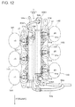
- FIG. 12 is a plan view illustrating the direct injector and the port injector illustrated in FIG. 9 .
- expressions that represent shapes mean not only what they refer to in a geometrically strict sense but also represent shapes including irregularities, chamfers, or the like that can exhibit the same level of effects.
- Directions of an engine described in the present embodiment is based on a driver's seat of an automobile with the engine installed in a vehicle body front portion.
- a figure based on a crankshaft direction front surface has left and right reversed, meaning that the left and right sides in the figure are respectively referred to as right and left sides.
- FIG. 1 is a front view illustrating an overall configuration of a V engine 1 according to the present embodiment, as viewed from the crankshaft direction front surface and is a partial cross-sectional view
- FIG. 2 is a plan view illustrating the overall configuration of the V engine 1 illustrated in FIG. 1 .
- the V engine 1 includes an engine main body 10 as well as devices for an air intake system 3 and a fuel supply system 7 .
- the engine main body 10 is a four-cycle six-cylinder SOHC (Single Over Head Camshaft) gasoline V engine, with a bank angle (bank narrow angle) of 60°.
- SOHC Single Over Head Camshaft
- the engine main body 10 includes: a cylinder block 11 having a V shape formed by bank of cylinders (banks) 12 A and 12 B; cylinder heads 2 A and 2 B respectively joined on upper sides of the left and the right banks 12 A and 12 B; and a crank casing 13 joined to a lower side of the cylinder block 11 .
- the cylinder block 11 having the V shape include the left and the right banks 12 A and 12 B offset from each other in a front and rear direction (crankshaft direction) in such a manner that the right side (left side in FIG. 2 ) bank 12 A is positioned on the front side and the left side (right side in FIG. 2 ) bank 12 B is positioned on the rear side.
- the left and the right banks 12 A and 12 B each include a corresponding one of sets of three cylinders 14 A and 14 B arranged side by side (see FIG. 12 ), and a single common crankshaft 15 is rotatably supported by the crank casing 13 in a lower area of the cylinders.
- the sets of three cylinders 14 A and 14 B are arranged side by side in the left and the right banks 12 A and 12 B in such a manner that the cylinder 14 A on the front most side in the right side bank 12 A serves as a first cylinder #1, and a second cylinder #2, a third cylinder #3, a fourth cylinder #4, a fifth cylinder #5, and a sixth cylinder #6 thereafter are alternately arranged on the left and right sides toward the rear side of the cylinder block 11 (see FIG. 12 ), with the number indicating the order of ignition of an ignition plug 22 described later (see FIG. 3 ).
- the cylinders 14 A and 14 B each have a cylindrical shape, with a piston 16 that reciprocates in axis directions L 3 and L 4 accommodated in each of the cylinders 14 A and 14 B.
- the piston 16 is formed to have the cylindrical shape and has a head portion closed and a pin hole formed through a body portion thereof in a radial direction.
- a connecting rod 17 has one end (small end (not illustrated)) accommodated in the body portion of the piston 16 . The small end of the connecting rod 17 is coupled to the piston 16 with a piston pin 162 provided through a pin hole.
- the crankshaft 15 with the connecting rod 17 converts the reciprocating motion (downward motion) of the piston 16 into rotational motion, and has a crank pin (not illustrated) in parallel with an axis passing through a rotation center of the crankshaft 15 .
- the connecting rod 17 has the other end (large end (not illustrated)) coupled to the crank pin.
- FIG. 3 is a cross-sectional view of a combustion chamber provided in the cylinder head illustrated in FIG. 1
- FIG. 4 is a schematic view of the combustion chamber illustrated in FIG. 3 as viewed in the IV-IV direction.
- FIG. 5 is a cross-sectional view of an intake port provided to the cylinder head illustrated in FIG. 1
- FIG. 6 is a schematic view of the intake port, illustrated in FIG. 5 , as viewed in the VI-VI direction.
- a combustion chamber 21 is formed at a position, in each of the cylinder heads 2 A and 2 B, corresponding to the cylinder 14 A or 14 B formed in the cylinder block 11 , and the ignition plug 22 is attached to each combustion chamber 21 as illustrated in FIG. 3 .
- the ignition plug 22 ignites and burns an air-fuel mixture supplied to the combustion chamber 21 and an air-fuel mixture mixed in the combustion chamber 21 or the cylinder (cylinders 14 A and 14 B).
- the cylinder heads 2 A and 2 B according to the present embodiment are positioned on the inner sides of the left and the right banks 12 A and 12 B.
- the combustion chambers 21 are each provided with two intake air inlets 23 and two exhaust air outlets 24 .
- the two intake air inlets 23 provided to each combustion chamber 21 , are aligned in a row along the arrangement direction of the cylinders 14 A and 14 B on the inner side of the banks 12 A and 12 B, and are opened to the combustion chamber 21 .
- the two exhaust air outlets 24 provided to each combustion chamber 21 are aligned in a row along the arrangement direction of the cylinders 14 A and 14 B on the outer side of the banks 12 A and 12 B, and are opened to the corresponding combustion chamber 21 .
- the two intake air inlets 23 provided to each combustion chamber 21 are each provided with a valve seat (seat surface) 231 , and are closed by an intake valve 25 provided to each of the intake air inlets 23 .
- the two exhaust air outlets 24 provided to each combustion chamber 21 are each provided with a valve seat (seat surface) 241 , and are closed by an exhaust valve 26 provided to each of the exhaust air outlets 24 .
- the cylinder heads 2 A and 2 B are provided with an intake port 27 and a discharge port 28 for each combustion chamber 21 .
- the intake ports 27 pass through the axes L 3 and L 4 of the cylinders 14 A and 14 B, and are disposed along directions (hereinafter, referred to as “intake-discharge direction”) orthogonal to the arrangement direction of the cylinders 14 A and 14 B and communicate with the two intake air inlets 23 opened to the combustion chamber 21 .
- the intake port 27 includes an upstream side port 271 and a downstream side port 272 .
- the upstream side port 271 serves as a flow path provided to each of the two intake air inlets 23 provided to each combustion chamber 21 , provided on the upstream side in the intake port 27 , and has an axis N passing through its cross-sectional center disposed on a plane passing through the axes L 3 and L 4 of the cylinders 14 A and 14 B.
- the upstream side port 271 is opened to a horizontal surface on the inner side of the cylinder heads 2 A and 2 B (see FIG. 5 ).
- the cylinder heads 2 A and 2 B are each provided with: an upstream side port opening 273 which has an oval shape elongated in the front and rear direction; and a flange (port injector attachment seat) 275 including a flat joining surface 274 provided around the opening (see FIG. 5 ).
- the downstream side port 272 serves as one flow passage provided to each intake air inlet 23 , and is provided to branch from the upstream side port 271 on the downstream side of the upstream side port 271 .
- each of the two downstream side ports 272 has an inlet provided to an outlet of the upstream side port 271 , and has an outlet provided to an inlet of the valve seat 231 provided to the intake air inlet 23 .
- the intake port 27 includes an arc portion 276 protruding downward in a center area of the intake port 27 on the upstream side of the valve seat 231 .
- the arc portion 276 is provided for bending the axis N passing through the cross-sectional center of the intake port 27 , so that a long intake air passage can be achieved, whereby the fuel injected from a port injector 91 is favorably mixed with air flowing in the intake port 27 .
- the discharge port 28 is provided along the intake and discharge direction on the opposite side of the intake port 27 relative to the combustion chamber 21 , and communicates with the two exhaust air outlets 24 opened to the combustion chamber 21 .
- the discharge port 28 includes upstream side ports 281 and downstream side ports (not illustrated).
- the upstream side ports 281 are flow paths each provided for the two exhaust air outlets 24 provided to each combustion chamber 21 , and are each provided on the upstream side of the discharge port 28 .
- the downstream side ports are flow paths each provided to the two exhaust air outlets 24 provided to each combustion chamber 21 and disposed on the downstream side of the two upstream side ports 281 such that the two upstream side ports 281 are joined, and have an axis passing through their centers disposed on planes passing through the axes of the cylinders 14 A and 14 B.
- the two upstream side ports 281 have an inlet provided to an outlet of the valve seat 241 provided to the exhaust air outlet 24 , and has an outlet provided to an inlet of the downstream side port.
- the engine main body 10 employs an offset crank structure as illustrated in FIG. 1 .
- a general V engine (the engine with the left and right banks not offset in the direction that is the same as the rotation direction of the crankshaft) has the axes L 1 and L 2 of the cylinders 14 A and 14 B in the left and the right banks 12 A and 12 B disposed in such a manner as to pass through a center P of the crankshaft 15 .
- the left and the right banks are at positions indicated by two dot chain lines in FIG. 1 .
- the axes L 1 and L 2 of the cylinders 14 A and 14 B of the left and the right banks 12 A and 12 B are translated in the direction that is same as the rotation direction (direction indicated by an arrow E) of the crankshaft 15 relative to the center P of the crankshaft 15 , with the distance between the center P of the crankshaft 15 and the upper surfaces of the cylinder heads 2 A and 2 B maintained.
- the axes L 1 and L 2 of the cylinders 14 A and 14 B of the left and the right banks 12 A and 12 B are offset to L 3 and L 4 with the bank angle maintained, and the axes L 1 and L 2 of the cylinders 14 A and 14 B move by ⁇ (offset amount).
- the right side bank (left side bank in FIG. 1 ) 2 A is positioned at a higher position than the left side bank (right side bank in FIG. 1 ) 2 B so that the level difference is provided, and the same level difference (H 2 -H 1 ) is provided between the inlet openings of the intake ports 27 of the right side bank 12 A and the left side bank 12 B.
- the engine main body 10 has an arrangement relationship in which the right side bank 12 A is disposed on the front side than the left side bank 12 B, and the right side bank 12 A is disposed at a position higher than the left side bank 12 B.
- a camshaft (not illustrated), a rocker arm (not illustrated), and the like as a valve driving mechanism are disposed in an upper area of the cylinder heads 2 A and 2 B, and a rocker cover 29 are attached to cover these members.
- the intake valve 25 and the exhaust valve 26 are opened/closed with the camshaft and the rocker arm at a predetermined timing.
- FIG. 7 is a front view of the air intake system 3 illustrated in FIG. 1 and FIG. 2 .
- FIG. 8 is a side view of the air intake system 3 illustrated in FIG. 1 and FIG. 2 , and is a partial cross-sectional view.
- the air intake system 3 is for turbo charging air to the intake port 27 provided to each combustion chamber 21 of the cylinder heads 2 A and 2 B of the left and the right banks 12 A and 12 B.
- the air intake system 3 includes: intake manifolds 4 A and 4 B joined to the cylinder heads 2 A and 2 B of the left and the right banks 12 A and 12 B; inter coolers 5 A and 5 B joined on the left and the right intake manifolds 4 A and 4 B; an outlet housing 31 that connects the left and the right inter coolers 5 A and 5 B to each other; and a supercharger 6 suspended from the outlet housing 31 .
- the supercharger 6 is driven by driving force transmitted from the crankshaft 15 (see FIG. 1 ) to send out air (intake air), and is attached between the left and the right banks 12 A and 12 B and above the left and the right rocker covers 29 .
- the supercharger 6 is positioned above crankshaft 15 , with the lower surface of the supercharger 6 disposed above the upper surface of the rocker cover 29 .
- the supercharger 6 discharges the supplied air (intake air) to the downstream side in a compressing manner, and thus increases the pressure of air (intake air) supplied to the engine main body 10 .
- the supercharger 6 according to the present embodiment includes a four-blade root supercharger.
- the supercharger 6 includes: a housing 61 ; an input rotation shaft 62 (see FIG. 8 ) that is rotatably supported by the housing 61 and protrudes to the forward side of the housing 61 ; and a pair of rotors 63 A and 63 B that are accommodated in the housing 61 and are rotated in opposite directions by the rotation of the input rotation shaft 62 .
- the housing 61 includes: a housing main body 61 A; an inlet housing 61 B joined to the rear surface of the housing main body 61 A; and a bearing housing 61 C joined to the front surface of the housing main body 61 A.
- the housing main body 61 A has an accommodating space in which the pair of rotors 63 A and 63 B are accommodated while being meshed with each other.
- the accommodating space is opened to the rear surface and an upper surface front area of the housing main body 61 A.
- the air taken in through a rear surface opening passes between the pair of rotors 63 A and 63 B accommodated in the accommodating space, and then is discharged through an upper surface front area opening 61 A 1 (see FIG. 8 ).
- the housing main body 61 A has an upper surface provided with a recess in which the upper surface front area opening 61 A 1 is formed.
- the recess has a rectangular shape with a short hand direction extending in the left and right direction and a longitudinal direction extending in the front and rear direction, and a flat joining surface is provided around the recess.
- the inlet housing 61 B has an intake air passage through which the air, taken into the housing main body 61 A, passes.
- the intake air passage is opened to the left side surface and the front surface of the inlet housing 61 B, and thus the air taken in through the side opening passes through the intake air passage and then is taken into the housing main body 61 A through the front surface opening.
- the inlet housing 61 B has a right side surface (a left side surface in FIG. 2 ) provided with a throttle body 64 .
- the throttle body 64 has a side surface provided with a cylindrical air inlet 64 A and has an inner portion provided with a throttle valve (not illustrated).
- a throttle valve not illustrated
- the bearing housing 61 C has a cylindrical bearing portion provided on the right side (left side in FIG. 2 ) of the front surface of the housing main body 61 A, so that the input rotation shaft 62 can be rotatably supported.
- the input rotation shaft 62 is disposed on the side of the right side bank 12 A.
- the input rotation shaft 62 is an input shaft that rotates when driving force is transmitted thereto from the crankshaft 15 , and has a belt 68 wound around a pulley 67 provided to a front end portion thereof and a pulley (not illustrated) provided to a front end portion of the crankshaft 15 as illustrated in FIG. 1 .
- the rotation of the crankshaft 15 is transmitted to the input rotation shaft 62 from the crankshaft 15 through the belt 68 , and thus the driving force is transmitted from the crankshaft 15 to the input rotation shaft 62 .
- the transmission of the driving force from the crankshaft 15 to the input rotation shaft 62 is not limited to a driving force transmission unit as a combination of the pulley 67 and the belt 68 , and a driving force transmission unit as a combination of a sprocket and a chain may be employed for example.
- the pair of rotors 63 A and 63 B are accommodated in the housing main body 61 A and are meshed with each other in the housing main body 61 A.
- the rotor 63 A (hereinafter, referred to as “drive rotor 63 A”) as one of the pair of rotors 63 A and 63 B has a rotation shaft including the input rotation shaft 62 , and the rotation of the input rotation shaft 62 causes the drive rotor 63 A to rotate in the same direction as the rotation direction of the input rotation shaft 62 .
- the other rotor 63 B (hereinafter, referred to as “driven rotor 63 B”) in mesh with the drive rotor 63 A is driven by the drive rotor 63 A to rotate in the direction opposite to the rotation direction of the drive rotor 63 A.
- driven rotor 63 B The other rotor 63 B (hereinafter, referred to as “driven rotor 63 B”) in mesh with the drive rotor 63 A is driven by the drive rotor 63 A to rotate in the direction opposite to the rotation direction of the drive rotor 63 A.
- air in a space enclosed by the drive rotor 63 A, the driven rotor 63 B, and the housing main body 61 A is pushed out to be discharged through the upper surface front area opening 61 A 1 of the housing main body 61 A.
- the outlet housing 31 distributes the air discharged from the supercharger 6 to the left and the right banks 12 A and 12 B, and is formed of light metal such as aluminum and synthetic resin such as FRP and prepreg.
- the outlet housing 31 can have a light weight, and can be integrally formed through forging of the light metal or from synthetic resin, which allows easier manufacturing of the same.
- the outlet housing 31 is provided to connect the left and the right banks 12 A and 12 B to each other at the center of the left and the right banks 12 A and 12 B in the front and rear direction.
- the outlet housing 31 has a rectangular parallelepiped shape that is short in the level direction, has a rectangular shape in plan view with a longitudinal direction extending along the left and right direction, a short hand direction extending along the front and rear direction, and has an upper surface inclined to have a level reducing gradually reducing from the rear side toward the front side (see FIG. 8 ).
- the outlet housing 31 has a distribution passage 32 through which the air discharged from the supercharger 6 is distributed to the left and the right banks 12 A and 12 B.
- the distribution passage 32 is formed along the outer shape of the outlet housing 31 , and has a ceiling surface 32 A inclined in such a manner that the level reduced from the rear side toward the front side, as in the case of the upper surface of the outlet housing 31 .
- the air (intake air) discharged from the supercharger 6 obliquely collides against the ceiling surface 32 A of the distribution passage 32 , resulting in a larger area in which intake air collides against the ceiling surface 32 A, and thus the colliding sound can be reduced compared with a configuration involving orthogonal collision against the ceiling surface 32 A.
- smaller sound radiation due to the discharge pressure from the supercharger 6 can be achieved.
- the distribution passage 32 is open at the center of the lower surface of the outlet housing 31 in the left and right direction.
- the outlet housing 31 has a center opening 33 formed in the same manner as the recess formed on the housing main body 61 A (the rectangular shape with the short hand direction extending in the left and right direction and the longitudinal direction extending along the front and rear direction), and has a flat joining surface provided therearound.
- the supercharger 6 is attached to the outlet housing 31 , with the joining surface of the housing main body 61 A joined to this joining surface with six bolts. Thus, the supercharger 6 is suspended from the center of the outlet housing 31 in the left and right direction.
- the distribution passage 32 is opened on both sides in the left and right direction on the lower surface of the outlet housing 31 .
- the left and the right openings 34 A and 34 B of the outlet housing 31 are each formed to have a rectangular shape smaller than the center opening 33 , with a flange with a flat joining surface provided therearound.
- the distribution passage 32 has a ceiling surface provided with a ridge 32 A 1 protruding downward at the center in the left and right direction.
- the ridge 32 A 1 is extends along the front and rear direction to divide the distribution passage 32 in two, that is, to left and right sides.
- the air introduced through the center opening 33 is distributed to left and right passage by the ridge 32 A 1 in such a manner that air distributed to the right is discharged from the right opening 34 A and the air introduced to the left is discharged from the left opening 34 B.
- the distribution of the air (intake air) discharged from the supercharger 6 to the left and the right banks 12 A and 12 B is facilitated, and thus the intake air is evenly supplied to the left and the right banks 12 A and 12 B.
- the distribution passage 32 is opened at the center of the rear surface of the outlet housing 31 in the left and right direction.
- the rear surface opening of the outlet housing 31 is an opening that communicates with a bypass path 691 described later, has a circular shape, and has a joining surface provided therearound.
- a bypass housing 69 is joined to this joining surface, and the bypass housing 69 is attached to the outlet housing 31 with two bolts.
- the bypass housing 69 includes the bypass path 691 through which the air discharged from the supercharger 6 is bypassed to the inlet housing 61 B.
- the bypass path 691 is opened on the front surface and the lower surface of the bypass housing 69 .
- the front surface opening of the bypass housing 69 is formed to be substantially the same as the rear surface opening of the outlet housing 31 , and communicates with the rear surface opening of the outlet housing 31 as described above.
- the bypass housing 69 has a lower surface provided with a bypass valve 66 .
- the bypass valve 66 has a lower surface connected to the inlet housing 61 B, and the bypass path 691 and the intake air passage communicate with each other via the bypass valve 66 .
- the air (intake air) discharged to the outlet housing 31 from the supercharger 6 partially returns to the intake air passage through the bypass path 691 , and thus the discharge air pressure (discharge intake air pressure) is adjusted.
- Returning air pressure (return intake air pressure) is adjusted with the bypass valve 66 .
- the left and the right inter coolers 5 A and 5 B respectively cools the air discharged from the supercharger 6 and distributed to the left and right sides, and are separately provided to the left and the right banks 12 A and 12 B while being positioned on both left and right sides of the supercharger 6 and above the left and the right rocker covers 29 .
- the left and right inter coolers 5 A and 5 B have the same structures on left and right sides, and each include: a casing 51 ; an inter cooler core 52 accommodated in the casing 51 ; and a plurality of collars 55 arranged around the casing 51 .
- the casing 51 accommodates the inter cooler core 52 and is formed of light metal such as aluminum or synthetic resin such as FRP and prepreg.
- the casing 51 can have a light weight, and can be formed through forging of the light metal or integrally formed from synthetic resin, which allows easier manufacturing of the same.
- the casing 51 has a rectangular parallelepiped shape and has a rectangular shape in plan view, with the short hand direction extending in the left and right direction and the longitudinal direction extending in the front and rear direction, and incorporates an intake air passage through which the air passes to be supplied to the intake manifolds 4 A and 4 B from the outlet housing 31 .
- the intake air passage is opened in the upper surface and the lower surface of the casing 51 .
- the upper surface opening of the casing 51 is formed in the same manner as the left and right openings 34 A and 34 B of the outlet housing 31 (the rectangular shape with the short hand direction extending in the left and right direction and the longitudinal direction extending in the front and rear direction) and has a flat joining surface provided therearound.
- the joining surface of the flange provided to the outlet housing 31 is joined to this joining surface.
- the lower surface opening of the casing 51 is formed in the same manner as the upper surface opening (the rectangular shape with the short hand direction extending in the left and right direction and the longitudinal direction extending in the front and rear direction) and has a flat joining surface provided therearound.
- the inter cooler core 52 cools the air flowing in the intake air passage, and is provided in such a manner that a pipe, through which cooling water, supplied from the outside of the casing 51 and discharged to the outside of the casing 51 , passes, is formed therethrough.
- the pipe has an inlet side 54 A (see FIG. 1 ) disposed on the upper side of the front surface of the casing 51 , and an outlet side 54 B (see FIG. 1 ) disposed on the lower side of the front surface of the casing 51 .
- bubbles in the cooling water is discharged upward.
- the plurality of collars 55 are provided for transmitting a load from the outlet housing 31 to the intake manifolds 4 A and 4 B and for protecting the casing 51 .
- the plurality of collars 55 according to the present embodiment include six collars that are arranged between the flange of the casing 51 and the outlet housing 31 at a substantially equal interval.
- the six collars 55 are each a cylindrical tube member in which a bolt is inserted, and disk-shaped flanges are provided on both sides of the tube member.
- the level of the collar 55 is the same as the level of the lower surface of the outlet housing 31 from the upper surface of the flange of the casing 51 , or is set to be higher than the level by a length corresponding to a gasket (not illustrated).
- the six bolt are each inserted through the flange of the outlet housing 31 , the collar 55 , and the flange of the casing 51 , and are each screwed with a female screw provided on a flange of the intake manifold 4 A, 4 B described later.
- the outlet housing 31 , the inter coolers 5 A and 5 B, and the intake manifolds 4 A and 4 B are integrated.
- the load is transmitted from the outlet housing 31 to the intake manifolds 4 A and 4 B, whereby the casing 51 is protected.
- the left and the right intake manifolds 4 A and 4 B are provided for distributing air (intake air) among the plurality of cylinders (the sets of three cylinders 14 A and 14 B) provided to the left and the right banks 12 A and 12 B, and is formed of light metal such as aluminum or synthetic resin such as an FRP or prepreg.
- the left and the right intake manifolds 4 A and 4 B can be light weight.
- the left and the right intake manifolds 4 A and 4 B formed through forging of the light metal or integrally formed from synthetic resin, which allows easier manufacturing of the same.
- the left and the right intake manifolds 4 A and 4 B are further provided for supporting the supercharger 6 , the outlet housing 31 , and the left and the right inter coolers 5 A and 5 B.
- the left and the right intake manifolds 4 A and 4 B are integrally formed while being provided between the lower surfaces of the inter coolers 5 A and 5 B and the joining surfaces of the cylinder heads 2 A and 2 B.
- the engine main body 10 employs the offset crank structure.
- the right side bank 12 A (the left side bank in FIG. 2 ) is positioned at a higher level than the left side bank 12 B (the right side bank in FIG. 2 ), so that the difference in level is provided.
- the same difference in level is provided between inlet openings of the intake ports 27 of the right side bank 12 A and the left side bank 12 B.
- the same difference in level (H 2 -H 2 ) is further provided between the attachment levels (the inlet openings of the intake ports 27 ) between the intake manifolds 4 A and 4 B according to the present embodiment in the right side bank 12 A and the left side bank 12 B.
- the left and the right intake manifolds 4 A and 4 B have a configuration in which the intake manifold 4 A (hereinafter, referred to as “right side intake manifold 4 A”) on the side of the right side bank 12 A (the left side bank in FIG. 7 ) is set to be shorter than the intake manifold 4 B (hereinafter, referred to as “left side intake manifold 4 B”) on the side of the left side bank 12 B (the right side bank in FIG. 7 ).
- the outlet housing 31 and the supercharger 6 suspended from the outlet housing 31 take a horizontal posture.
- the right side intake manifold 4 A has a support rigidity higher than that of the left side intake manifold 4 B.
- the input rotation shaft 62 (see FIG. 2 ) is disposed on the side of the right side bank 12 A and thus is disposed on the side (the side of the right side intake manifold 4 A) with a higher support rigidity and a front side position (the right side bank 12 A) of the engine main body 10 , and thus can suppress the vibration of the supercharger 6 .
- the left and the right intake manifolds 4 A and 4 B are curved from the left and right inter coolers 5 A and 5 B toward the left and the right banks 12 A and 12 B along the outer shape of the rocker cover 29 , and support the supercharger 6 , the outlet housing 31 , and the left and the right inter coolers 5 A and 5 B.
- the left and the right intake manifolds 4 A and 4 B include surge portions facing the joining surfaces of the inter coolers 5 A and 5 B, and include branch passages branched from the surge portions to the intake ports of the left and the right cylinder heads 2 B.
- the surge portions are opened to the joining surfaces of the inter coolers 5 A and 5 B, and the branched passages are opened to the joining surfaces joined to the intake ports 27 .
- the left and the right intake manifolds 4 A and 4 B have surge portion openings formed in the same manner as the lower surface opening of the casing 51 (a rectangular shape with the short hand direction extending in the left and right direction and the longitudinal direction extending in the front and rear direction) with flanges with a flat joining surface provided therearound.
- the joining surfaces of the flanges provided to the inter coolers 5 A and 5 B are joined to the joining surfaces, and six bolts are inserted through the flange of the outlet housing 31 , the collars 55 , and the flange of the casing 51 to be screwed with the female screws provided on the flanges of the intake manifolds 4 A and 4 B.
- the outlet housing 31 , the inter coolers 5 A and 5 B, and the intake manifolds 4 A and 4 B are integrated.
- the intake port joining surface openings of the left and the right intake manifolds 4 A and 4 B are formed in the same manner as the upstream side port openings of the cylinder heads 2 A and 2 B (oval shape elongated in the front and rear direction), and have flanges with flat joining surfaces provided therearound. The joining surfaces are joined to the joining surfaces of the cylinder heads 2 A and 2 B.
- Four bolts are provided for each of the left and the right banks 12 A and 12 B. The bolts are inserted through the flanges of the intake manifolds 4 A and 4 B to be screwed with male screwed provided to the flanges 275 of the cylinder heads 2 A and 2 B.
- the left and the right intake manifolds 4 A and 4 B integrated with the outlet housing 31 and the inter coolers 5 A and 5 B, are attached to the cylinder heads 2 A and 2 B.
- a coupling wall is provided between adjacent branched passages in the left and the right intake manifolds 4 A and 4 B.
- the coupling wall couples the adjacent branched passages to each other, closes a space between the adjacent branched passages, and forms a tunnel shaped space between the banks 12 A and 12 B.
- the coupling wall has a wall surface provided with a reinforcement rib.
- the coupling wall forms the tunnel shaped space between the left and the right banks 12 A and 12 B, and thus both side wall surfaces of the coupling wall have a function of guiding air flowing in the tunnel shaped space.
- the left and the right intake manifolds 4 A and 4 B have lower end portions provided with left and right coupling portions.
- the left and the right coupling portions are provided between lower end portions of the left and the right intake manifolds 4 A and 4 B so that the lower end portions are coupled to each other.
- the left and the right coupling portions may be provided on both sides in the front and rear direction, may be provided at a plurality of portions along the front and rear direction at an interval, or may be provided in such a manner as to form a surface so that a bottom wall can be formed.
- the rigidity of the left and the right intake manifolds 4 A and 4 B can further be improved.
- the supercharger 6 is disposed on the inner side of the closed cross-sectional structure enclosed by the outlet housing 31 , the left and right inter coolers 5 A and 5 B, and the left and the right intake manifolds 4 A and 4 B, as viewed from the front surface in the direction of the crankshaft 15 .
- the suspended supporting structure of the supercharger 6 can have an even higher rigidity, whereby more stable supporting can be achieved.
- the outlet housing 31 , the left and right inter coolers 5 A and 5 B, and the left and the right intake manifolds 4 A and 4 B as separate structures can be assembled by being fastened to each other with bolts.
- a structure in which the pipes and the components of the fuel injection devices 8 and 9 are accommodated on the inner sides of the left and the right banks can be easily assembled.
- the outlet housing 31 , the left and right inter coolers 5 A and 5 B, and the left and the right intake manifolds 4 A and 4 B are formed as separate structures.
- the structure can conform with the difference between the side of the right side bank (high bank) 12 A and the side of the left side bank (low bank) 12 B simply by changing the levels of the left and the right intake manifolds 4 A and 4 B.
- the left and right inter coolers 5 A and 5 B can be shared by the left and the right banks 12 A and 12 B.
- the outlet housing 31 and the casing 51 of the left and right inter coolers 5 A and 5 B are formed of rigid resin or with light metal, and thus can have lighter weight.
- a weight load on the left and the right intake manifolds 4 A and 4 B can be reduced.
- the durability of the left and the right intake manifolds 4 A and 4 B can be improved.
- the lighter air intake system 3 leads to a lower center of gravity of the V engine 1 and thus contributes to improvement of the maneuverability of the vehicle (prevention of under steering).
- a sound absorbing material may be provided between the components (the outlet housing 31 , the left and the right inter coolers 5 A and 5 B, and the left and the right intake manifolds 4 A and 4 B) and the supercharger 6 .
- the sound radiation from the supercharger 6 is reduced, and a load due to attack of the supercharger 6 to the fuel related components at the time of collision can be reduced.
- the supercharger 6 is suspended from the outlet housing 31 has a flat rectangular parallelepiped shape extending in the direction of the left and the right banks.
- this suspending structure should not be construed in a limiting sense.
- the charger may be placed and fixed on the left and right inter coolers 5 A and 5 B.
- FIG. 9 is a front view illustrating a cylinder injection device and a port injection device illustrated in FIG. 1 .
- FIG. 10 is a plan view illustrating a state in which an electrical connector is attached to a connector attachment member in FIG. 9 .
- FIG. 11 is a front view illustrating the direct injector and the port injector illustrated in FIG. 9 .
- FIG. 12 is a plan view illustrating the direct injector and the port injector illustrated in FIG. 9 .
- the fuel supply system includes two types of fuel injection devices 8 and 9 which is a cylinder injection type directly injecting fuel into the combustion chamber 21 provided to each of the cylinders 14 A and 14 B and a port injection type injecting fuel in to the intake port 27 provided to each combustion chamber 21 .
- the cylinder injection fuel injection device 8 (hereinafter, referred to a “cylinder injection device 8 ”) includes: direct injectors 81 each provided for a corresponding one of the cylinders 14 A and 14 B in the left and the right banks 12 A and 12 B; high pressure delivery pipes 82 A and 82 B commonly provided to the plurality of direct injectors 81 in the left and the right banks 12 A and 12 B; and a high pressure fuel pump (not illustrated) that supplies fuel to the high pressure delivery pipes 82 A and 82 B.
- the direct injectors 81 are for directly injecting fuel into the combustion chambers 21 provided to the cylinders 14 A and 14 B, and are disposed along the intake and discharge direction at positions one the outer side of the intake port 27 in the cylinder radial direction as illustrated in FIG. 3 . More specifically, the direct injectors 81 are arranged to have the center axis disposed on a plane passing through the axis L 3 (L 4 ) of the cylinder 14 A( 14 B) in a lower area of the downstream side port 272 as a bifurcated portion of the intake port 27 . Thus, the direct injectors 81 are arranged to be orthogonal to the arrangement direction of the cylinders 14 A ( 14 B) and are alternately arranged on the inner sides of the left and the right banks 12 A and 12 B in plan view.
- the direct injector 81 includes: a nozzle portion 81 a with a small diameter; a body portion 81 b with a larger diameter than the nozzle portion 81 a ; a delivery pipe coupling portion (not illustrated) having a larger diameter than the nozzle portion 81 a and a smaller diameter than the body portion 81 b ; and a connector attachment member 81 d (first connector attachment member) provided on a radially outer side of the body portion 81 b .
- the nozzle portion 81 a has a distal end provided with an injection hole (not illustrated) with which fuel, supplied from the high pressure fuel pump, is injected while spreading in a conical form.
- the body portion 81 b accommodates a control device (not illustrated) that controls an injected amount and an injected timing of the fuel.
- High pressure delivery pipes 82 A and 82 B are coupled to the delivery pipe coupling portion, and fuel is supplied from the high pressure fuel pump through high pressure delivery pipes 82 A and 82 B.
- the electrical connector 83 (first electrical connector) is attached to the connector attachment member 81 d .
- a direction in which the electrical connector 83 is attached to the connector attachment member 81 d is the radial direction of the direct injector 81 (body portion 81 b ).
- the electrical connector 83 is attached to the connector attachment member 81 d from the outer side in the radial direction.
- the electrical connector 83 is detached from the connector attachment member 81 d toward the outer side in the radial direction.
- the direct injectors 81 have the connector attachment members 81 d alternately arranged between the left and the right banks 12 A and 12 B which facing each other in oblique parallel directions in plan view.
- the connector attachment members 81 d on the right side bank 12 A are orientated obliquely rearward and the connector attachment members 81 d on the left side bank 12 B (the right side bank in FIG. 10 ), offset rearward relative to the right side bank 12 A, are orientated obliquely forward.
- the direct injector 81 has the center axis inclined to be directed obliquely upward in the space between the left and the right banks 12 A and 12 B, and is attached in such a manner that the fuel injected from the direct injector 81 (injection axis S) is oriented into the cylinder.
- the high pressure delivery pipes 82 A and 82 B supply fuel to the direct injector 81 .
- the direct injectors 81 are arranged to be orthogonal to the arrangement direction of the cylinders 14 A ( 14 B).
- the high pressure delivery pipes 82 A ( 82 B) are arranged along the arrangement direction of the cylinders 14 A ( 14 B).
- the high pressure delivery pipes 82 A and 82 B are disposed on the inner sides of the left and the right banks 12 A and 12 B and are coupled to the delivery pipe coupling portions of the direct injectors 81 (see FIG. 9 ).
- the fuel supplied to the high pressure delivery pipes 82 A and 82 B is supplied to the direct injector 81 through the high pressure delivery pipes 82 A and 82 B.
- the control device accommodated in the body portion 81 b is controlled with an electrical signal supplied from the electrical connector 83 attached to the connector attachment member 81 d , in such a manner that a desired amount of fuel is supplied to the nozzle portion 81 a at a desired injection timing.
- the fuel supplied to the nozzle portion 81 a is injected through a nozzle port into a cylinder (cylinders 14 A and 14 B) in such a manner as to spread in a conical form.
- the high pressure delivery pipes 82 A and 82 B provided to the left and the right banks 12 A and 12 B have inlets on a rear end portion side.
- the high pressure delivery pipe 82 A (hereinafter, referred to as “right side high pressure delivery pipe 82 A”) provided to the right side bank 12 A has a rear end portion 82 A 1 connected to the high pressure fuel pump through a fuel pipe 84 a .
- the rear end portion 82 A 1 of the right side high pressure delivery pipe 82 A and a rear end portion 82 B 1 of the high pressure delivery pipe 82 B (hereinafter, referred to as “left side high pressure delivery pipe 82 B”) provided to the left side bank 12 B are connected to each other through a fuel pipe 84 b .
- the fuel supplied from the high pressure fuel pump to the right side high pressure delivery pipe 82 A is distributed to the left side high pressure delivery pipe 82 B.
- the fuel supplied to the right side high pressure delivery pipe 82 A is supplied to the direct injector 81 provided to the right side bank 12 A.
- the fuel supplied to the left side high pressure delivery pipe 82 B is supplied to the direct injector 81 provided to the left side bank 12 B.
- the engine main body 10 employs the offset crank structure.
- the right side bank 12 A (the left side bank in FIG. 9 ) is disposed at a position higher than the left side bank 12 B (the right side bank in FIG. 9 ). Due to the level difference, the same level difference is provided between the intake ports 27 on the right side bank 12 A and the left side bank 12 B.
- the same level difference is provided also between the direct injectors 81 according to the present embodiment in the right side bank 12 A and the left side bank 12 B.
- the same level difference is provided between the connector attachment members 81 d.
- the same level difference is provided between attachment levels of the high pressure delivery pipes 82 A and 82 B according to the present embodiment in the right side bank 12 A and the left side bank 12 B.
- the port injection fuel injection device 9 (hereinafter, referred to as a “port injection device 9 ”) includes a port injector 91 provided to the intake port 27 provided for each combustion chamber 21 in the left and the right banks 12 A and 12 B; low pressure delivery pipes 92 A and 92 B commonly provided for a plurality of the port injectors 91 in the left and the right banks 12 A and 12 B, and a low pressure fuel pump (not illustrated) that supplied fuel to the low pressure delivery pipes 92 A and 92 B.
- a port injector 91 provided to the intake port 27 provided for each combustion chamber 21 in the left and the right banks 12 A and 12 B
- low pressure delivery pipes 92 A and 92 B commonly provided for a plurality of the port injectors 91 in the left and the right banks 12 A and 12 B
- a low pressure fuel pump (not illustrated) that supplied fuel to the low pressure delivery pipes 92 A and 92 B.
- the port injectors 91 inject fuel to the intake port 27 provided for each combustion chamber 21 , and are arranged along the intake and discharge direction at positions on the same side as the direct injectors 81 relative to the intake port 27 as illustrated in FIG. 5 . More specifically, the port injector 91 has the center axis positioned on a plane passing through the axis L 3 (L 4 ) of the cylinders 14 A ( 14 B) at a position where the intake port 27 is most protruded toward the inner side of the bank of the cylinder block 11 . Thus, the center axis of the port injector 91 is disposed on the same plane as the center axis of the direct injector 81 .
- the port injectors 91 are arranged to be orthogonal to the arrangement direction of the cylinders 14 A ( 14 B). Thus, the port injectors 91 are alternately disposed on the inner sides of the left and the right banks 12 A and 12 B in plan view.
- the fuel (injection axis T) injected from the port injector 91 is distributed to the two branches of the downstream side ports 272 on the downstream side of the intake port 27 , and thus is evenly distributed on both sides of the plane passing through the axis L 3 (L 4 ) of the cylinder 14 A ( 14 B) and the center axis of the direct injectors 81 .
- an injection axis T indicating the injection direction of the port injector 91
- an angle between the injection axis T indicating the injection direction of the port injector 91 and the lower surface of the cylinder head 2 A ( 2 B) is larger than an angle between a straight line, which passes through an injection position of the port injector 91 and contacts a lower most surface of the arc portion 276 , and the lower surface of the cylinder head 2 A ( 2 B).
- An injection axis S of the port injector 91 and the injection axis T of the direct injector 81 are in parallel with each other or cross each other on a front side in the fuel injection direction (see FIG. 3 ).
- an angle between the injection axis S of the port injector 91 and the lower surface of the cylinder head 2 A ( 2 B) is equal to or larger than an angle between the injection axis T of the direct injector 81 and the lower surface of the cylinder head 2 A ( 2 B).
- the fuel injected from the direct injector 81 spreads against a tumble flow generated in the cylinder 14 A ( 14 B).
- the port injector 91 includes: a nozzle portion 91 a with a small diameter; a body portion 91 b with a larger diameter than the nozzle portion 91 a ; a delivery pipe coupling portion (not illustrated) having a larger diameter than the nozzle portion 91 a and a smaller diameter than the body portion 91 b ; and a connector attachment member 91 d (second connector attachment member) provided on a radially outer side of the body portion 91 b .
- the nozzle portion 91 a has a distal end provided with an injection hole (not illustrated) with which fuel, supplied from the low pressure fuel pump, is injected while spreading in a conical form toward two downstream ports.
- the body portion 91 b accommodates a control device (not illustrated) that controls an injected amount and an injected timing of the fuel.
- Low pressure delivery pipes 92 A and 92 B are coupled to the delivery pipe coupling portion, and fuel is supplied from the low pressure fuel pump through low pressure delivery pipes 92 A and 92 B.
- the electrical connector 93 (second electrical connector) is attached to the connector attachment member 91 d .
- a direction in which the electrical connector 93 is attached to the connector attachment member 91 d is an obliquely upward direction relative to the port injector 91 (body portion 91 b ).
- the electrical connector 93 is attached to the connector attachment member 91 d from the obliquely upward direction.
- the electrical connector 93 is detached from the connector attachment member 91 d toward the obliquely upward direction.
- the port injector 91 has the connector attachment member 91 d arranged toward the outer side of the bank. Specifically, the nozzle portion 81 a of the port injector 91 is arranged to protrude toward the intake port 27 (cylinder head 2 A) beyond the joining surfaces of the cylinder head 2 A and the intake manifolds 4 A and 4 B. The nozzle portion 91 a of the port injector 91 has a distal end positioned in the intake port 27 .
- the center axis of the port injector 91 is inclined toward obliquely upper side in the space between the left and the right banks 12 A and 12 B.
- the port injector 91 is attached in such a manner that the injected fuel (injection axis T) is oriented to the umbrella center of the intake valve 25 .
- the low pressure delivery pipes 92 A and 92 B supply fuel to the port injector 91 and are provided on the inner sides of the left and the right banks 12 A and 12 B to be overlapped with the high pressure delivery pipes 82 A and 82 B as illustrated in FIG. 12 .
- the delivery pipe coupling portion of the port injector 91 is coupled to the low pressure delivery pipes 92 A and 92 B.
- the fuel supplied to the low pressure delivery pipes 92 A and 92 B is supplied to the port injector 91 through the low pressure delivery pipe 92 A.
- the control device accommodated in the body portion 91 b is controlled with an electrical signal supplied from the electrical connector 93 attached to the connector attachment member 91 d , in such a manner that a desired amount of fuel is supplied to the nozzle portion 91 a at a desired injection timing.
- the fuel supplied to the nozzle portion 91 a is injected through a nozzle port into two downstream side ports in such a manner as to spread to be in a conical form.
- the low pressure delivery pipes 92 A and 92 B provided to the left and the right banks 12 A and 12 B have inlets on a front end portion side.
- the low pressure delivery pipe 92 A (hereinafter, referred to as “right side low pressure delivery pipe 92 A”) provided to the right side bank 12 A has a front end portion 92 A 1 connected to a fuel pipe (branch pipe) 94 b branched from the fuel pipe (main pipe) 94 a .
- the low pressure delivery pipe 92 B (hereinafter, referred to as “left side low pressure delivery pipe 92 B”) provided to the left side bank 12 B has a front end portion 94 B 1 connected to the fuel pipe (main pipe) 94 a .
- the fuel discharged from the low pressure fuel pump is supplied to the right side low pressure delivery pipe 92 A and to the left side low pressure delivery pipe through the fuel pipes 94 a and 94 b .
- the fuel supplied to the right side low pressure delivery pipe 92 A is supplied to the port injector 91 provided to the right side bank 12 A.
- the fuel provided to the left side low pressure delivery pipe 92 B is supplied to the port injector 91 provided to the left side bank 12 B.
- the engine main body 10 employs the offset crank structure.
- the right side bank 12 A (the left side bank in FIG. 9 ) is disposed at a position higher than the left side bank 12 B (the right side bank in FIG. 9 ). Due to the level difference, the same level difference of the intake ports 27 is provided between the right side bank 12 A and the left side bank 12 B. Thus, the same level difference is provided also between the port injectors 91 according to the present embodiment in the right side bank 12 A and the left side bank 12 B. The same level difference is provided between the connector attachment members 91 d.
- the same level difference is provided between attachment levels of the low pressure delivery pipes 92 A and 92 B according to the present embodiment in the right side bank 12 A and the left side bank 12 B.
- the V engine 1 has the valve seat 231 provided at the intake air inlet 23 opened to the combustion chamber 21 , and has the arc portion 276 protruding downward in a center area of the intake port 27 on the upstream side of the valve seat 231 .
- the injection axis T indicating the injection direction of the port injector 91 is orientated in a direction in which the fuel injected from the port injector 91 passes through the lower area of the arc portion 276 .
- the direct injector 81 and the port injector 91 can be efficiently arranged, and the fuel injected from the port injector 91 is favorably mixed with air flowing in the intake port 27 .
- the direct injector 81 can be disposed in the lower area of the bifurcated downstream side ports 272 , and thus can be efficiently arranged.
- the fuel injected from the direct injector 81 spreads against the tumble flow generated in the cylinders 14 A and 14 B. Thus, the mixing of the fuel and the air is facilitated in the cylinders 14 A and 14 B.
- the direct injectors 81 and the port injectors 91 are arranged to be orthogonal to the arrangement direction of the cylinders 14 A and 14 B.
- the high pressure delivery pipes 82 A and 82 B supplying fuel to the direct injectors 81 can be arranged in the arrangement direction of the cylinders 14 A and 14 B.
- the low pressure delivery pipes 92 A and 92 B supplying fuel to the port injectors 91 can be arranged in the arrangement direction of the cylinders 14 A and 14 B.
- the intake manifolds 4 A and 4 B can be fixed to the cylinder heads 2 A and 2 B, in a state where the port injectors 91 are fixed to the intake manifolds 4 A and 4 B.
- the thickness of the port injector attachment seat can be reduced compared with a configuration where the nozzle portion 91 a of the port injector 91 is positioned closer to the intake manifolds 4 A and 4 B than the joining surface 274 .
- the fuel (injection axis T) injected from the port injector 91 flows toward the umbrella center of the intake valve 25 , and thus can be suppressed from attaching to the inner wall surface of the intake port 27 .
- the direct injectors 81 and the port injectors 91 can be arranged on the inner sides of the banks of the cylinder blocks 11 in a concentrated manner.
- the plurality of direct injector 81 include the connector attachment members 81 d , to which the electrical connectors 83 are connected, protruding outward from the body portions 81 b in the radial direction and having different levels between the banks.
- the electrical connectors 83 can be attached to the direct injectors 81 , with the interference of the electrical connectors 83 between the direct injector 81 in one bank 12 A ( 12 B) and the direct injectors 81 in the other bank 12 B ( 12 A) within a limited space between the banks.
- the electrical connector 83 can be attached to the connector attachment member 81 d from the outer side of the direct injector 81 in the radial direction.
- the electrical connector 83 can be detached from the connector attachment member 81 d toward the outer side of the direct injector 81 in the radial direction.
- the direct injector 81 disposed in the left side bank 12 B is disposed at a lower position than the direct injector 81 disposed in the right side bank 12 A.
- the electrical connectors 83 can be attached to the direct injectors 81 , with the interference of the electrical connectors 83 between the direct injector 81 in one bank 12 A on the right and the direct injectors 81 in the other bank on the left prevented within a limited space between the banks.
- the connector attachment member 81 d is oriented obliquely backward.
- the connector attachment member 81 d is oriented obliquely forward.
- the electrical connectors 83 can be attached to the connector attachment members 81 d of the direct injectors 81 disposed in the right side bank 12 A, and the electrical connectors 83 can be attached to the connector attachment members 81 d of the direct injectors 81 disposed in the left side bank 12 B, with the interference of the electrical connectors 83 between the direct injector 81 in one bank 12 A on the right and the direct injectors 81 in the other bank on the left prevented.
- the plurality of port injectors 91 include the connector attachment members 91 d , to which the electrical connectors 93 are connected, protruding outward from the body portions 91 b in the radial direction.
- the electrical connectors 93 can be attached to the port injectors, with the interference of the electrical connectors 93 between the port injector 91 in one bank 12 A ( 12 B) and the port injectors 91 in the other bank 12 B ( 12 A) prevented.
- the electrical connector 93 can be attached to the connector attachment member 91 d from the obliquely upper side of the port injector 91 .
- the electrical connector 93 can be detached from the connector attachment member 91 d toward the obliquely upper side of the port injector 91 .
- the low pressure delivery pipes 92 A and 92 B overlap with the high pressure delivery pipes 82 A and 82 B in plan view.
- the low pressure delivery pipes 92 A and 92 B do not largely protrude outward beyond the high pressure delivery pipes 82 A and 82 B.
- the high pressure delivery pipes 82 A and 82 B and the low pressure delivery pipes 92 A and 92 B are closely arranged, whereby efficient pipe operations of the high pressure delivery pipes 82 A and 82 B and the low pressure delivery pipes 92 A and 92 B can be achieved.
- the high pressure delivery pipes 82 A and 82 B and the low pressure delivery pipes 92 A and 92 B are disposed on the inner sides of the banks of the cylinder blocks 11 in a concentrated manner. Thus, an efficient pipe operations of the high pressure delivery pipes 82 A and 82 B and the low pressure delivery pipes 92 A and 92 B can be achieved.
- the high pressure delivery pipes 82 A and 82 B and the low pressure delivery pipes 92 A and 92 B in the left and the right banks 12 A and 12 B are alternately arranged while being shifted from each other in the upper and lower direction, as viewed in the direction of the crankshaft 15 , and thus can be arranged between the V banks.
- the higher bank (right side bank 12 A) and the lower bank (left side bank 12 B) are shifted in the direction of the crankshaft 15 in plan view.
- the high pressure delivery pipes 82 A and 82 B and the low pressure delivery pipes 92 A and 92 B in the left and the right banks 12 A and 12 B are alternately arranged while being shifted from each other in the front and rear direction, and thus can be more easily arranged between the V banks.
- the inlet side of the high pressure delivery pipes 82 A and 82 B and the inlet side of the low pressure delivery pipes 92 A and 92 B are positioned on sides to each other in the arrangement direction of the cylinders 14 A and 14 B.
- the high pressure delivery pipes 82 A and 82 B and the low pressure delivery pipes 92 A and 92 B need not to be in a complex arrangement to be prevented from interfering each other on the fuel supply inlet side.
- the intake manifolds 4 A and 4 B can be fixed to the cylinder heads 2 A and 2 B, in the state where the low pressure delivery pipes 92 A and 92 B are fixed to the intake manifolds 4 A and 4 B.
- the direct injectors 81 and the port injectors 91 as well as their fuel supply pipes are arranged to be surrounded by the outlet housing 31 , the supercharger 6 , and the left and the right banks 12 A and 12 B. This is expected to be effective for safety at the time of collision, and a cooling effect with the enclosed internal space guiding the air flow due to vehicle traveling.
Applications Claiming Priority (1)
| Application Number | Priority Date | Filing Date | Title |
|---|---|---|---|
| PCT/JP2014/084348 WO2016103408A1 (fr) | 2014-12-25 | 2014-12-25 | Moteur |
Related Parent Applications (1)
| Application Number | Title | Priority Date | Filing Date |
|---|---|---|---|
| PCT/JP2014/084348 Continuation WO2016103408A1 (fr) | 2014-12-25 | 2014-12-25 | Moteur |
Publications (2)
| Publication Number | Publication Date |
|---|---|
| US20170248103A1 US20170248103A1 (en) | 2017-08-31 |
| US10344729B2 true US10344729B2 (en) | 2019-07-09 |
Family
ID=56149503
Family Applications (1)
| Application Number | Title | Priority Date | Filing Date |
|---|---|---|---|
| US15/595,042 Active US10344729B2 (en) | 2014-12-25 | 2017-05-15 | Engine including direct injector and port injector |
Country Status (5)
| Country | Link |
|---|---|
| US (1) | US10344729B2 (fr) |
| EP (1) | EP3239515A4 (fr) |
| JP (1) | JP6332776B2 (fr) |
| CN (1) | CN107002618B (fr) |
| WO (1) | WO2016103408A1 (fr) |
Cited By (1)
| Publication number | Priority date | Publication date | Assignee | Title |
|---|---|---|---|---|
| US10989220B2 (en) * | 2016-12-06 | 2021-04-27 | Hitachi, Ltd. | Casing and turbo machine |
Families Citing this family (4)
| Publication number | Priority date | Publication date | Assignee | Title |
|---|---|---|---|---|
| IL255916B (en) * | 2017-11-26 | 2020-08-31 | Yacob Rafaeli | Rotary valve assembly for an engine head in an internal combustion engine |
| JP6536668B1 (ja) * | 2017-12-28 | 2019-07-03 | マツダ株式会社 | エンジン |
| US10415518B2 (en) * | 2017-12-29 | 2019-09-17 | Chien-Hsiang Huang | Supercharger structure for an all terrain vehicle or a utility vehicle |
| WO2020145158A1 (fr) * | 2019-01-07 | 2020-07-16 | 三菱自動車工業株式会社 | Culasse |
Citations (11)
| Publication number | Priority date | Publication date | Assignee | Title |
|---|---|---|---|---|
| JPH01240765A (ja) | 1988-03-19 | 1989-09-26 | Mazda Motor Corp | V型エンジンの燃料供給装置 |
| US4932368A (en) | 1988-01-28 | 1990-06-12 | Mazda Motor Corporation | Suction arrangement for internal combustion engine |
| JPH1037752A (ja) | 1996-07-26 | 1998-02-10 | Hitachi Ltd | 内燃機関の吸気装置 |
| US6269797B1 (en) * | 1997-11-19 | 2001-08-07 | Yamaha Hatsudoki Kabushiki Kaisha | Cylinder head and manifold arrangement for injected engine |
| US20020014228A1 (en) * | 2000-08-02 | 2002-02-07 | Tetsurou Yamada | In-cylinder injection engine with supercharger |
| US20050235961A1 (en) * | 2004-04-23 | 2005-10-27 | Denso Corporation | Fuel injector designed to optimize pattern of fuel spray |
| US20060207555A1 (en) | 2005-03-18 | 2006-09-21 | Yukikazu Ito | Internal combustion engine provided with double system of fuel injection |
| US20060207527A1 (en) * | 2005-03-18 | 2006-09-21 | Tetsuya Saeki | Dual-injector fuel injection engine |
| US20090235890A1 (en) | 2008-03-18 | 2009-09-24 | Yamaha Hatsudoki Kabushiki Kaisha | Intake control device for an engine |
| US8047180B2 (en) * | 2008-03-28 | 2011-11-01 | Honda Motor Co., Ltd. | Intake air control system of V-type internal combustion engine |
| US20160201593A1 (en) * | 2015-01-14 | 2016-07-14 | Ford Global Technologies, Llc | Method and system for fuel injection |
Family Cites Families (2)
| Publication number | Priority date | Publication date | Assignee | Title |
|---|---|---|---|---|
| JP2609297B2 (ja) * | 1988-07-29 | 1997-05-14 | マツダ株式会社 | V型エンジンの吸気構造 |
| EP2369167B1 (fr) * | 2003-11-07 | 2013-06-05 | Yamaha Hatsudoki Kabushiki Kaisha | Dispositif d'alimentation en carburant et véhicule l'utilisant |
-
2014
- 2014-12-25 EP EP14909015.1A patent/EP3239515A4/fr not_active Withdrawn
- 2014-12-25 CN CN201480084063.8A patent/CN107002618B/zh active Active
- 2014-12-25 JP JP2016565766A patent/JP6332776B2/ja active Active
- 2014-12-25 WO PCT/JP2014/084348 patent/WO2016103408A1/fr active Application Filing
-
2017
- 2017-05-15 US US15/595,042 patent/US10344729B2/en active Active
Patent Citations (17)
| Publication number | Priority date | Publication date | Assignee | Title |
|---|---|---|---|---|
| US4932368A (en) | 1988-01-28 | 1990-06-12 | Mazda Motor Corporation | Suction arrangement for internal combustion engine |
| JPH0674777B2 (ja) | 1988-03-19 | 1994-09-21 | マツダ株式会社 | V型エンジンの燃料供給装置 |
| JPH01240765A (ja) | 1988-03-19 | 1989-09-26 | Mazda Motor Corp | V型エンジンの燃料供給装置 |
| JP3557314B2 (ja) | 1996-07-26 | 2004-08-25 | 株式会社日立製作所 | 内燃機関の吸気装置 |
| JPH1037752A (ja) | 1996-07-26 | 1998-02-10 | Hitachi Ltd | 内燃機関の吸気装置 |
| US6269797B1 (en) * | 1997-11-19 | 2001-08-07 | Yamaha Hatsudoki Kabushiki Kaisha | Cylinder head and manifold arrangement for injected engine |
| EP1179676A1 (fr) | 2000-08-02 | 2002-02-13 | Yamaha Hatsudoki Kabushiki Kaisha | Moteur à combustion interne à injection directe |
| JP2002048035A (ja) | 2000-08-02 | 2002-02-15 | Yamaha Motor Co Ltd | 過給機付筒内噴射エンジン |
| US20020014228A1 (en) * | 2000-08-02 | 2002-02-07 | Tetsurou Yamada | In-cylinder injection engine with supercharger |
| US20050235961A1 (en) * | 2004-04-23 | 2005-10-27 | Denso Corporation | Fuel injector designed to optimize pattern of fuel spray |
| US20060207555A1 (en) | 2005-03-18 | 2006-09-21 | Yukikazu Ito | Internal combustion engine provided with double system of fuel injection |
| US20060207527A1 (en) * | 2005-03-18 | 2006-09-21 | Tetsuya Saeki | Dual-injector fuel injection engine |
| WO2006100943A1 (fr) | 2005-03-18 | 2006-09-28 | Toyota Jidosha Kabushiki Kaisha | Moteur a combustion interne a double systeme d'injection de carburant |
| JP4495211B2 (ja) | 2005-03-18 | 2010-06-30 | トヨタ自動車株式会社 | 2系統燃料噴射式エンジン |
| US20090235890A1 (en) | 2008-03-18 | 2009-09-24 | Yamaha Hatsudoki Kabushiki Kaisha | Intake control device for an engine |
| US8047180B2 (en) * | 2008-03-28 | 2011-11-01 | Honda Motor Co., Ltd. | Intake air control system of V-type internal combustion engine |
| US20160201593A1 (en) * | 2015-01-14 | 2016-07-14 | Ford Global Technologies, Llc | Method and system for fuel injection |
Non-Patent Citations (2)
| Title |
|---|
| Chinese Office Action and Search Report, dated Sep. 4, 2018, for Chinese Application No. 201480084063.8, along with an English translation. |
| Japanese Office Action dated Dec. 1, 2017 issued in corresponding Japanese Patent Application No. 2016-565766 with an English Translation. |
Cited By (1)
| Publication number | Priority date | Publication date | Assignee | Title |
|---|---|---|---|---|
| US10989220B2 (en) * | 2016-12-06 | 2021-04-27 | Hitachi, Ltd. | Casing and turbo machine |
Also Published As
| Publication number | Publication date |
|---|---|
| CN107002618A (zh) | 2017-08-01 |
| CN107002618B (zh) | 2019-06-18 |
| EP3239515A1 (fr) | 2017-11-01 |
| WO2016103408A1 (fr) | 2016-06-30 |
| US20170248103A1 (en) | 2017-08-31 |
| JPWO2016103408A1 (ja) | 2017-07-06 |
| EP3239515A4 (fr) | 2018-08-29 |
| JP6332776B2 (ja) | 2018-05-30 |
Similar Documents
| Publication | Publication Date | Title |
|---|---|---|
| US10344729B2 (en) | Engine including direct injector and port injector | |
| US9062645B2 (en) | Fuel feed system for V-type engine | |
| US10961948B2 (en) | Engine device | |
| JP6492643B2 (ja) | V型エンジン | |
| JP5308477B2 (ja) | 4サイクルエンジン | |
| EP1001160B1 (fr) | Moteur à combustion | |
| EP1681459B1 (fr) | Dispositif d'alimentation en carburant, vehicule et procede d'assemblage de dispositif d'alimentation en carburant | |
| EP2915990B1 (fr) | Agencement de collecteur d'admission, culasse et injecteurs | |
| JP6459045B2 (ja) | エンジン | |
| JP6500434B2 (ja) | V型エンジン | |
| JP2017133493A (ja) | V型2シリンダ汎用エンジンの燃料供給装置 | |
| US9683487B2 (en) | Outboard motor | |
| JP7211216B2 (ja) | エンジンの燃料供給装置 | |
| JP7386193B2 (ja) | エンジン装置 | |
| US9677467B2 (en) | Vertical engine | |
| JP6455707B2 (ja) | 車両用内燃機関 | |
| US20150198117A1 (en) | Gaseous fuel feeding system | |
| JP6296374B2 (ja) | V型エンジン | |
| EP3656996B1 (fr) | Moteur comprenant un compresseur de suralimentation mécanique | |
| CN117722301A (zh) | 一种二冲程活塞发动机进气管部件冗余设计结构 | |
| EP3855007A1 (fr) | Véhicule du type à selle | |
| GB2554922B (en) | Exhaust duct for internal combustion engine | |
| JP6296373B2 (ja) | V型エンジン | |
| WO2016103403A1 (fr) | Moteur en v |
Legal Events
| Date | Code | Title | Description |
|---|---|---|---|
| AS | Assignment |
Owner name: MITSUBISHI JIDOSHA ENGINEERING KABUSHIKI KAISHA, J Free format text: ASSIGNMENT OF ASSIGNORS INTEREST;ASSIGNORS:NISHIDONO, TAKEHIRO;TAKAI, JUNJI;YOKOYAMA, TOSHIO;REEL/FRAME:042387/0899 Effective date: 20170427 Owner name: MITSUBISHI JIDOSHA KOGYO KABUSHIKI KAISHA, JAPAN Free format text: ASSIGNMENT OF ASSIGNORS INTEREST;ASSIGNORS:NISHIDONO, TAKEHIRO;TAKAI, JUNJI;YOKOYAMA, TOSHIO;REEL/FRAME:042387/0899 Effective date: 20170427 |
|
| STPP | Information on status: patent application and granting procedure in general |
Free format text: NOTICE OF ALLOWANCE MAILED -- APPLICATION RECEIVED IN OFFICE OF PUBLICATIONS |
|
| STPP | Information on status: patent application and granting procedure in general |
Free format text: PUBLICATIONS -- ISSUE FEE PAYMENT VERIFIED |
|
| STCF | Information on status: patent grant |
Free format text: PATENTED CASE |
|
| CC | Certificate of correction | ||
| AS | Assignment |
Owner name: MITSUBISHI JIDOSHA KOGYO KABUSHIKI KAISHA, JAPAN Free format text: CHANGE OF ADDRESS;ASSIGNOR:MITSUBISHI JIDOSHA KOGYO KABUSHIKI KAISHA;REEL/FRAME:055472/0944 Effective date: 20190104 |
|
| MAFP | Maintenance fee payment |
Free format text: PAYMENT OF MAINTENANCE FEE, 4TH YEAR, LARGE ENTITY (ORIGINAL EVENT CODE: M1551); ENTITY STATUS OF PATENT OWNER: LARGE ENTITY Year of fee payment: 4 |