US10249960B2 - Distributed antenna system and method of manufacturing a distributed antenna system - Google Patents
Distributed antenna system and method of manufacturing a distributed antenna system Download PDFInfo
- Publication number
- US10249960B2 US10249960B2 US14/354,197 US201214354197A US10249960B2 US 10249960 B2 US10249960 B2 US 10249960B2 US 201214354197 A US201214354197 A US 201214354197A US 10249960 B2 US10249960 B2 US 10249960B2
- Authority
- US
- United States
- Prior art keywords
- waveguide
- openings
- elliptical
- different
- antenna system
- Prior art date
- Legal status (The legal status is an assumption and is not a legal conclusion. Google has not performed a legal analysis and makes no representation as to the accuracy of the status listed.)
- Active, expires
Links
Images


Classifications
-
- H—ELECTRICITY
- H01—ELECTRIC ELEMENTS
- H01Q—ANTENNAS, i.e. RADIO AERIALS
- H01Q1/00—Details of, or arrangements associated with, antennas
-
- H—ELECTRICITY
- H01—ELECTRIC ELEMENTS
- H01Q—ANTENNAS, i.e. RADIO AERIALS
- H01Q21/00—Antenna arrays or systems
- H01Q21/0006—Particular feeding systems
- H01Q21/0037—Particular feeding systems linear waveguide fed arrays
- H01Q21/0043—Slotted waveguides
-
- H—ELECTRICITY
- H01—ELECTRIC ELEMENTS
- H01Q—ANTENNAS, i.e. RADIO AERIALS
- H01Q1/00—Details of, or arrangements associated with, antennas
- H01Q1/007—Details of, or arrangements associated with, antennas specially adapted for indoor communication
-
- H—ELECTRICITY
- H01—ELECTRIC ELEMENTS
- H01Q—ANTENNAS, i.e. RADIO AERIALS
- H01Q13/00—Waveguide horns or mouths; Slot antennas; Leaky-waveguide antennas; Equivalent structures causing radiation along the transmission path of a guided wave
- H01Q13/10—Resonant slot antennas
- H01Q13/12—Longitudinally slotted cylinder antennas; Equivalent structures
-
- H—ELECTRICITY
- H01—ELECTRIC ELEMENTS
- H01Q—ANTENNAS, i.e. RADIO AERIALS
- H01Q13/00—Waveguide horns or mouths; Slot antennas; Leaky-waveguide antennas; Equivalent structures causing radiation along the transmission path of a guided wave
- H01Q13/20—Non-resonant leaky-waveguide or transmission-line antennas; Equivalent structures causing radiation along the transmission path of a guided wave
-
- H—ELECTRICITY
- H01—ELECTRIC ELEMENTS
- H01P—WAVEGUIDES; RESONATORS, LINES, OR OTHER DEVICES OF THE WAVEGUIDE TYPE
- H01P3/00—Waveguides; Transmission lines of the waveguide type
- H01P3/12—Hollow waveguides
- H01P3/127—Hollow waveguides with a circular, elliptic, or parabolic cross-section
-
- H—ELECTRICITY
- H01—ELECTRIC ELEMENTS
- H01P—WAVEGUIDES; RESONATORS, LINES, OR OTHER DEVICES OF THE WAVEGUIDE TYPE
- H01P3/00—Waveguides; Transmission lines of the waveguide type
- H01P3/12—Hollow waveguides
- H01P3/14—Hollow waveguides flexible
-
- Y—GENERAL TAGGING OF NEW TECHNOLOGICAL DEVELOPMENTS; GENERAL TAGGING OF CROSS-SECTIONAL TECHNOLOGIES SPANNING OVER SEVERAL SECTIONS OF THE IPC; TECHNICAL SUBJECTS COVERED BY FORMER USPC CROSS-REFERENCE ART COLLECTIONS [XRACs] AND DIGESTS
- Y10—TECHNICAL SUBJECTS COVERED BY FORMER USPC
- Y10T—TECHNICAL SUBJECTS COVERED BY FORMER US CLASSIFICATION
- Y10T29/00—Metal working
- Y10T29/49—Method of mechanical manufacture
- Y10T29/49002—Electrical device making
- Y10T29/49016—Antenna or wave energy "plumbing" making
Definitions
- the present invention relates to a distributed antenna system for transmitting and/or receiving radio frequency, RF, signals.
- the present invention further relates to a method of manufacturing a distributed antenna system of the aforementioned type.
- coaxial cable can be operated only up to the so-called cut-off frequency which is a function of the cable diameter.
- the frequency range supported by this cable is a very important characteristic. The higher the operational frequency is the smaller the coaxial cable has to be.
- the attenuation increases with decreasing diameter and increasing frequency.
- the relatively high attenuation incapacitates coaxial radiating cable to provide RF coverage at frequencies above 4 GHz in long distance systems like tunnels. Repeaters have to be installed in very short distance.
- said antenna system comprising at least one elliptical waveguide having a basically elliptical cross-section, wherein said waveguide comprises a plurality of openings.
- an elliptical waveguide having a basically elliptical cross-section and a plurality of openings may advantageously be employed as a distributed antenna system, because the elliptical waveguide as such is optimally suited for transmitting electromagnetic signals, especially in the RF range, over longer distances since it has a particularly low attenuation even for higher frequencies within said RF range.
- no repeaters or the like have to be provided even in large-scale installations with overall waveguide lengths of several hundred meters or more.
- the distributed antenna system comprises one single elliptical waveguide which has a plurality of openings, thus forming a very simple configuration of a distributed antenna system.
- the elliptical waveguide may easily be optimised for different frequency ranges.
- the distributed antenna system according to the embodiments can more easily be scaled to even higher frequencies in the RF range, i.e. to frequencies above 3 GHz, than prior art distributed antenna systems which comprise discrete antenna elements or radiating coaxial cables.
- said elliptical waveguide comprises at least one corrugated section which on the one hand increases mechanical flexibility of the waveguide and thus facilitates deployment of the waveguide according to the embodiments in complex scenarios, where e.g. bending of the waveguide is required. Furthermore, the bandwidth of the distributed antenna system according to the embodiments is increased by providing corrugations.
- a distributed antenna system which comprises first and second sections of elliptical waveguide which are not corrugated and which are connected to each other by a third section of elliptical waveguide which is corrugated and thus offers an increased mechanical flexibility facilitating bending.
- the complete elliptical waveguide is of the corrugated type.
- the at least one elliptical waveguide is manufactured in one single piece, e.g. as a kind of endless material, which further facilitates installation in the field, because there is no requirement of connecting various smaller waveguide sections by welding or the like in the field.
- the openings which enable to radiate electromagnetic waves from the interior of the elliptical waveguide to a surrounding area are comprised within corrugated sections of the waveguide, preferably in radially outer portions of the corrugations.
- said openings may also be provided in non-corrugated sections of the elliptical waveguide. Combinations of both variants are also possible.
- At least one of said openings comprises a substantially elliptical cross-section.
- Circular or polygonal cross-sections or other shapes are also possible for implementing the openings within the elliptical waveguide.
- different openings which are provided at different length coordinates of said waveguide, are arranged at different angular positions with respect to a major axis of said elliptical cross-section, which advantageously enables to control a coupling strength for the electromagnetic coupling that characterizes the leakage of RF signals from the interior of the elliptical waveguide to the surrounding area.
- the coupling loss decreases when the openings are placed closer to the small axis and increases when the openings are placed closer to the large axis.
- the angular position increases with a distance from a feeding end of the elliptical waveguide, to which an RF signal transmitter or transceiver may be attached, whereby a longitudinal attenuation for signals travelling within the elliptical waveguide from said feeding end to a second end may be accounted for in that radiating openings which are close to the feeding end are provided such that they enable less coupling between the interior and the surroundings of the elliptical waveguide as compared to further openings which are remote from the feeding end.
- These further openings may rather be arranged such that they provide an increased electromagnetic coupling between the interior and the outside of the elliptical waveguide to account for the increased longitudinal attenuation the RF signals have suffered prior to arriving at the remote portions of the elliptical waveguide.
- a very homogenous distribution of radiated power from the different openings of the elliptical waveguide along the length coordinate (i.e., parallel to a longitudinal axis) of the elliptical waveguide may be attained.
- the cross-section of the waveguide may also comprise a circular shape, e.g. the length of the major axis of the elliptical cross-section is substantially equal to the length of the minor axis of the elliptical cross-section.
- different sections of the elliptical waveguide may be defined which per se comprise a different level of electromagnetic coupling, whereby the RF signal level radiated by the various openings may be controlled independently for the various longitudinal sections of the elliptical waveguide.
- a first longitudinal section of the elliptical waveguide may be defined which offers a strong coupling and thus a corresponding RF signal supply outside the radiating elliptical waveguide
- a further longitudinal section of the elliptical waveguide may be defined with openings that offer less electromagnetic coupling and thus a correspondingly smaller RF signal supply outside the radiating elliptical waveguide.
- a longitudinal attenuation of the waveguide may advantageously be compensated by choosing an appropriate position of the openings with respect to e.g. the major axis of the elliptical cross-section.
- different ones of said plurality of openings each comprise a different geometry and/or orientation with respect to a surface and/or a longitudinal axis of the waveguide.
- a first number of openings of the elliptical waveguide may comprise elliptical or substantially elliptical geometry as already mentioned above, whereas further openings of the elliptical waveguide according to the embodiments comprise a non-elliptical geometry, i.e. a polygonal shape or other geometries.
- a further embodiment it is also possible to vary at least one physical property (size, shape, orientation of a normal vector of the opening's surface) of the openings along the length coordinate of the waveguide.
- These measures inter alia also enable to compensate a longitudinal attenuation along the length coordinate. For instance, a size of the openings may increase along the length coordinate to compensate for the longitudinal attenuation.
- one or more openings of the elliptical waveguide comprise an orientation with respect to the surface of the elliptical waveguide such that a normal vector of an opening surface of the respective opening is parallel to a normal vector of the respective surface portion of the waveguide the opening is arranged in, i.e. parallel to a radial coordinate of said waveguide.
- the openings may either be arranged on the radially outer sections of the waveguide, for example with an orientation such that a surface normal is basically arranged in a radial direction, or on the radially inner sections of the corrugated waveguide.
- a combination of both variants is also possible for different openings.
- Orientations of openings such that their surface normal vectors are basically arranged in a partially non-radial (i.e., axial) direction are also possible according to a further embodiment, e.g. on sloped wall portions of the elliptical waveguide defined between radially inner and radially outer sections of corrugations.
- said at least one elliptical waveguide is configured to transmit electromagnetic waves with a frequency of at least 4 GHz.
- said at least one elliptical waveguide comprises a longitudinal attenuation of about 4 dB per 100 meters for electromagnetic waves with a frequency of about 6 GHz.
- an elliptical waveguide according to the embodiments for the same frequency band of about 6 GHz, has an attenuation of just 4 dB/100 m. That means the coverage length of a system made with radiating elliptical waveguides according to the embodiments can be approximately 4 times longer compared to a prior art solution with coaxial cable.
- said system comprises at least one transmitter for transmitting RF signals to said at least one elliptical waveguide and/or at least one receiver for receiving RF signals from said at least one elliptical waveguide.
- the aforementioned devices may e.g. be arranged at a first, i.e. feeding, end of the waveguide and/or at an opposing second end. It is also possible to provide a transceiver which combines transmitting and receiving functionality.
- a further solution to the object of the present invention is given by a method of manufacturing a distributed antenna system, wherein an elliptical waveguide is provided (i.e., at least one elliptical waveguide), and wherein a plurality of openings are created within said elliptical waveguide.
- an elliptical waveguide i.e., at least one elliptical waveguide
- the openings are created by milling and/or drilling and/or laser cutting respective wall portions of the elliptical waveguide.
- an elliptical corrugated waveguide of the E60 type manufactured by Radio Frequency Systems could be used as a basis for manufacturing the distributed antenna system according to the embodiments.
- the openings defined in the elliptical waveguide allow electromagnetic waves transmitted by the elliptical waveguide to leave the waveguide to some extent for distribution to free space, which is surrounding the elliptical waveguide.
- RF signal supply i.e. for the purpose of wireless communications can be established in a location which comprises at least one distributed antenna system according to the embodiments.
- a very simple setup for a distributed antenna system comprises only one single elliptical waveguide comprising a plurality of openings, i.e. the single radiating elliptical waveguide represents the distributed antenna system, according to this very simple embodiment.
- the plurality of openings represent individual radiating sections (“antennas”) providing radio coverage.
- a reception of signals is also possible by receiving a portion of electromagnetic signals travelling in an area surrounding the elliptical waveguide by means of said openings and by forwarding said received portions of the electromagnetic field surrounding the elliptical waveguide to one or both ends of the elliptical waveguides, where a receiver device could be arranged in addition to a transmitter device providing the RF signal(s) to be transmitted via the distributed antenna system according to the embodiments.
- the openings are created after a step of installing said waveguide in the field, wherein said step of installing said waveguide in the field preferably comprises bending at least one section of said waveguide.
- FIG. 1 schematically depicts a top view of a distributed antenna system comprising a single elliptical waveguide according to a first embodiment
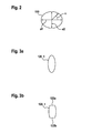
- FIG. 2 schematically depicts a cross-section of an elliptical waveguide according to an embodiment
- FIGS. 3 a , 3 b depict a possible geometry for the radiating openings according to further embodiments
- FIG. 4 schematically depicts a partial cross-section of an elliptical waveguide according to an embodiment
- FIGS. 5 a , 5 b schematically depict further partial cross-sections of elliptical waveguides according to the embodiments
- FIG. 6 depicts a perspective view of an elliptical waveguide according to an embodiment
- FIG. 7 depicts an angular position of the radiating openings of the waveguide versus a length of the waveguide according to an embodiment
- FIG. 8 depicts a simplified flow chart of a method according to an embodiment
- FIG. 9 a to 9 f schematically depict top views of waveguides with different configurations of radiating openings according to the embodiments.
- FIG. 1 schematically depicts a top view of a distributed antenna system 100 according to a first embodiment.
- the distributed antenna system 100 comprises an elliptical waveguide 110 which has a basically elliptical cross-section.
- the elliptical cross-section of the elliptical waveguide 110 is exemplarily depicted by FIG. 2 .
- the basically elliptical cross-section as depicted by FIG. 2 may be defined by a major axis a 1 and a minor axis a 2 , which is arranged orthogonal to the major axis a 1 .
- An angle ⁇ serves to define an angular position of openings comprised within the elliptical waveguide 110 as detailed below.
- the elliptical waveguide 110 has several openings 120 _ 1 , 120 _ 2 , 120 _ 3 distributed along its longitudinal axis (not shown).
- the openings 120 _ 1 , 120 _ 2 , 120 _ 3 advantageously enable electromagnetic waves travelling within the elliptical waveguide 110 to be transmitted from the interior of the elliptical waveguide 110 to a surrounding area outside the elliptical waveguide 110 , i.e. to be radiated.
- each of the openings 120 _ 1 , 120 _ 2 , 120 _ 3 defines a radiating element or antenna, respectively.
- a minimum configuration according to the embodiments for the distributed antenna system 100 comprises a single elliptical waveguide 110 as depicted by FIG. 1 and a plurality of openings 120 _ 1 , 120 _ 2 , 120 _ 3 comprised therein.
- radio frequency signals are transmitted by the per se known mechanism of (hollow) waveguide transmission along the longitudinal axis of the elliptical waveguide 110 , i.e. in FIG. 1 from the feeding end 130 a at the left to the further end 130 b at the right.
- portions of the RF signal are radiated to the surrounding space thus providing radio coverage for an area surrounding the elliptical waveguide 110 .
- Reception of RF signals can also be effected, wherein RF signals radiated onto the openings 120 _ 1 , 120 _ 2 , 120 _ 3 at least partly couple into the elliptical waveguide 110 and are guided to e.g. an optional receiver 150 .
- the devices 140 , 150 (as well as any other active device used together with the waveguide 110 —will preferably be colocated, e.g. at the first end 130 a of the waveguide 110 or the second end 130 b —according to a further advantageous embodiment to facilitate service and maintenance tasks.
- RF signals received by the waveguide 110 through its openings 120 _ 1 , 120 _ 2 , 120 _ 3 are transmitted in both directions (upstream and downstream) of the length coordinate l.
- FIG. 3 a schematically depicts an opening 120 _ 1 provided within the elliptical waveguide 110 of FIG. 1 .
- the opening 120 _ 1 comprises a basically elliptical shape, which may be attained by providing an elliptical waveguide that has no openings, and by defining the openings 120 _ 1 therein by means of drilling and/or milling and/or laser cutting.
- FIG. 3 b depicts a further geometry for the openings 120 _ 1 , 120 _ 2 , 120 _ 3 within the elliptical waveguide 110 ( FIG. 1 ), which comprises a basically elliptical shape with two basically flat edge sections 122 a , 122 b , which are arranged in antipodal regions of the basically elliptical shape along its major axis.
- openings 120 _ 1 are also possible, e.g. polygonal shapes or circular shapes or the like.
- FIG. 4 schematically depicts a partial cross-section of an elliptical waveguide 110 a according to a further embodiment.
- the elliptical waveguide 110 a comprises corrugations, which are defined by alternately providing different radii r 1 , r 2 as seen from a central axis or longitudinal axis ca of the elliptical waveguide 110 a .
- the corrugations improve a frequency range for which low attenuation, particularly low longitudinal attenuation, can be attained.
- the corrugated section 110 a comprises an increased mechanical flexibility and hence advantageously enables to deploy the elliptical waveguide 110 a in complicated mounting situations which required bending.
- a plurality of openings 120 _ 1 , . . . , 120 _ 6 of the elliptical waveguide section 110 a are provided in the radially outer sections, which comprise a distance r 2 from the central axis ca.
- all openings 120 _ 1 , . . . , 120 _ 6 comprise basically the same angular position, cf. the angle ⁇ as defined above with reference to FIG. 2 .
- openings 120 _ 1 , . . . , 120 _ 6 could alternatively or additionally also be comprised within other sections of the elliptical waveguide 110 a , for example in the radially inner sections at a distance r 1 as seen from the central axis ca or at the sloped connecting sections between the radially inner sections at radius r 1 and the radially outer sections at radius r 2 .
- openings 120 _ 1 , . . . , 120 _ 6 could alternatively or additionally also be arranged at different angular positions, i.e. ⁇ >0°.
- FIG. 5 a depicts a further embodiment of an elliptical waveguide 110 b that may be used for the distributed antenna system 100 .
- only every second radially outer section of the corrugated surface of the elliptical waveguide 110 b as seen along the central axis ca, cf. FIG. 4 , comprises a respective opening 120 _ 7 , 120 _ 8 for radiation of electromagnetic waves from the interior of the elliptical waveguide 110 b to a surrounding space.
- FIG. 5 b depicts a further embodiment of the invention, wherein different sections of the elliptical waveguide 110 c comprise openings of different geometry.
- a first portion 110 c ′ of the elliptical waveguide 110 c comprises an opening 120 _ 9 comprising a first, comparatively small, geometry
- a second section 110 c ′′ of the elliptical waveguide 110 c comprises an opening 120 _ 10 comprising a comparatively large geometry, and so on.
- FIG. 6 depicts a perspective view of a distributed antenna system 100 a according to a further embodiment.
- a radio frequency signal source (not depicted) could be connected to the elliptical waveguide 110 d at said feeding end 130 a to couple RF signals to be transmitted via said elliptical waveguide 110 d into said waveguide 110 d .
- receiving means could also be arranged at the feeding end 130 a or at the other end 130 b of the elliptical waveguide 110 d as depicted by FIG. 6 .
- the distributed antenna system 100 a as depicted by FIG. 6 provides a comparatively homogenous RF signal supply over its whole length, i.e. up to the second end 130 b.
- a longitudinal attenuation is comparatively low as compared to radiating coaxial cables or the like.
- the operating frequency range of the elliptical waveguide 110 d is easily scalable by altering the geometry of the waveguide.
- different openings 120 _ 1 , 120 _ 2 , . . . of the elliptical waveguide 110 d ( FIG. 6 ), which are provided at different length coordinates l 1 , l 2 of said waveguide 110 d , are arranged at different angular positions with respect to the major axis a 1 ( FIG. 2 ) of the elliptical cross-section of the waveguide.
- This advantageously enables to control a coupling strength between the interior of the elliptical waveguide 110 d and the exterior which enables to compensate a longitudinal attenuation of RF signals travelling within the elliptical waveguide 110 d.
- the angular position ⁇ as defined by FIG. 2 increases with a distance 1 from the feeding end 130 a ( FIG. 6 ) of the elliptical waveguide 110 d .
- a comparatively high coupling attenuation is attained for electromagnetic radiation passing said opening.
- FIGS. 4 to 6 depict annularly corrugated waveguides
- the waveguide according to the embodiments may instead also comprises helical corrugations (not shown).
- a waveguide according to the embodiments may be uncorrugated or comprise annular or helical corrugations. These different types of corrugations may also be combined within several waveguides of the system 100 according to the embodiments.
- FIG. 7 exemplarily depicts an angular position ⁇ for the various openings 120 _ 1 , 120 _ 2 , . . . over the longitudinal coordinate l.
- the angular position linearly changes from a first value ⁇ 1 to a second value ⁇ 2 between the positions l 0 , lx along the elliptical waveguide.
- Further embodiments may also provide for a gradual, i.e. stepwise, or exponential or logarithmic change of the angular position ⁇ over length l, or combinations thereof, which may e.g. be applied to different length sections of the waveguide.
- the variation of the angular position ⁇ over length l may advantageously be employed for defining different length sections of the waveguide 110 d which provide for different radiated RF field strengths.
- a first range of the angular position ⁇ of the openings may be contemplated which offers a higher degree of radiated energy
- a further range of the angular position ⁇ of the respective openings may be contemplated which offers a smaller degree of radiated energy adapted to the smaller tunnel diameter.
- the arbitrary variation of the angular position ⁇ to account for the surrounding areas' volume may be combined with the—basically monotonous—variation of the angular position ⁇ that compensates for longitudinal attenuation, which depends on the length coordinate l, i.e. the distance of a specific waveguide section from the feeding end 130 a.
- ⁇ In analogy to varying an angular position ⁇ of the openings along the length coordinate l of the waveguide 110 , according to a further embodiment it is also possible to vary at least one physical property (size, shape, orientation of a normal vector of the opening's surface) of the openings 120 _ 1 , 120 _ 2 , . . . along the length coordinate l of the waveguide 110 .
- These measures inter alia also enable to compensate a longitudinal attenuation along the length coordinate l to some extent. For instance, a size of the openings 120 _ 1 , 120 _ 2 , . . . may increase along the length coordinate l to compensate for the longitudinal attenuation. Combinations of the aforementioned measures are also possible.
- a single waveguide with changing openings or changing angular positions of the openings along its length coordinate l it is also possible to provide different waveguide sections or complete waveguides which have openings of same, i.e. constant properties, such as e.g. angular position, over the whole waveguide section or complete waveguide.
- a change of the properties along a length coordinate l may be effected when connecting in series the various waveguide sections or waveguides.
- different openings within the waveguide may also be arranged in several groups, wherein each group comprises a predetermined number of openings with the same parameters (angular position, size, and the like) along the length coordinate.
- different groups of openings may be arrange one after the other along the length coordinate.
- a waveguide 110 FIG. 1
- said waveguide may comprise a second number of openings of a second type, and so on. It is also possible to provide several openings in a first length section of the wave guide, and to provide no openings in a subsequent length section of the waveguide.
- FIG. 8 depicts a simplified block diagram of a method according to an embodiment.
- a first step 200 an elliptical waveguide is provided.
- a further step 210 a plurality of openings 120 _ 1 , 120 _ 2 , 120 _ 3 ( FIG. 1 ) are provided in the elliptical waveguide thus enabling electromagnetic waves being radiated from the interior to the exterior of the elliptical waveguide.
- a radiating elliptical waveguide 110 , 110 d of the type as depicted by FIG. 1 or FIG. 6 is obtained.
- corrugations may be provided to the elliptical waveguide, either after the step 200 of providing the elliptical waveguide of FIG. 8 or in the course of providing, i.e. manufacturing the elliptical waveguide.
- an elliptical corrugated waveguide of the E60 type manufactured by Radio Frequency Systems could be used within step 200 as a basis for manufacturing the distributed antenna system according to the embodiments.
- the waveguide 110 may be covered by a cable jacket (not shown) which also covers the radiating openings without significantly changing radiation characteristics.
- At least some of said openings 120 _ 1 , 120 _ 2 , . . . are created after a step of installing said waveguide 110 d ( FIG. 6 ) in the field, wherein said step of installing said waveguide 110 d in the field preferably comprises bending at least one section of said waveguide 110 d .
- a very precise creation of radiating sections having said openings 120 _ 1 , 120 _ 2 , . . . is possible, because the position of the openings 120 _ 1 , 120 _ 2 , . . . may be defined depending on the specific mounting condition of the elliptical waveguide 110 d in the field, e.g. in a tunnel or the like.
- the openings 120 _ 1 , 120 _ 2 , . . . are made manually by a technician who assesses the mounting condition of the elliptical waveguide 110 d in the field and who defines the positions of openings in the elliptical waveguide 110 d depending thereon, e.g. assisted by measurement and/or simulation equipment for measuring and/or calculating a resulting electromagnetic field distribution with respect to the position of the waveguide 110 d and its openings.
- the benefits of the system according to the embodiments are a low longitudinal loss that allows using radiating waveguides for long distances at high frequencies. About 4 times longer passive systems can be achieved compared to conventional radiating coaxial cable.
- variable positioning of openings 120 _ 1 , 120 _ 2 , . . . (e.g., slots) on the circumference of the waveguide 100 d (cf. the angular position ⁇ ) enable gradual adjustment of coupling loss.
- the elliptical waveguides 110 a , 110 b , 110 c , 110 d according to the embodiments are flexible and can advantageously be produced in very long, virtually endless, length. Installation is significantly faster and efficient compared with rectangular waveguides.
- only a first number of openings may be defined in the waveguide, e.g. according to a standard RF signal radiation behavior required in many cases. Further openings may even be defined in a waveguide installed in the field, i.e. manually by a service technician with a drilling machine or the like, to optimally account for individual mounting conditions.
- the embodiments offer a particularly easy and quick installation due to the arbitrary lengths of waveguide material 110 d that can be supplied in one piece (i.e., no connecting work as welding or the like required in the field), a homogeneous radiated RF signal coverage comparing to existing systems with discrete antennas or conventional radiating coaxial cables, easy implementation of the openings in the waveguide (e.g., by milling of an existing corrugated waveguide), low longitudinal loss of the radiating waveguide at high frequencies up to the 40 GHz range and higher, an opportunity of using standard accessories (connectors, clamps etc.) in case different waveguides have to be connected in the field, because the radiating waveguides according to the embodiments may be derived from standard-type waveguides or they may at least basically comprise the same geometrical form, especially at their end sections 130 a , 130 b ( FIG. 6 ).
- At least one waveguide 110 of the system 100 is not required to have an exactly elliptical cross-section in a strict mathematical sense.
- FIG. 9 a to 9 f schematically depict top views of waveguides 110 e , . . . , 110 j with different configurations of radiating openings according to the embodiments.
- the various radiating openings are not individually assigned reference numerals, they are rather symbolized by elliptical and/or circular and/or rectangular shapes in FIG. 9 a to 9 f .
- a cable jacket which may cover the waveguide(s) 110 e , . . . , 110 j for electrical isolation and protection, is not depicted.
- FIG. 9 a depicts a radiating waveguide 110 e which comprises along its length coordinate l two rows of radiating openings with identical geometry and equal inter-opening spacing along the length coordinate l.
- Each row can be interpreted to be arranged at a specific angular position ⁇ as explained above.
- a single row or more than two rows are also possible.
- subsequent openings along the length coordinate l of a same row may also have varying angular position, whereby e.g. a helical configuration of openings (not shown) may be attained on the surface of the waveguide 110 e .
- FIG. 1 depicts a radiating waveguide 110 e which comprises along its length coordinate l two rows of radiating openings with identical geometry and equal inter-opening spacing along the length coordinate l.
- Each row can be interpreted to be arranged at a specific angular position ⁇ as explained above.
- a single row or more than two rows are also possible.
- FIG. 9 b depicts a radiating waveguide 110 f which comprises along its length coordinate l two rows of radiating openings with identical geometry and equal inter-opening spacing per row along the length coordinate l.
- each row alternately comprises two openings and therebetween a length section comprising no openings.
- a first row of the FIG. 9 b embodiment comprises two openings within the first length section ls 1 , whereas in a subsequent second length section ls 2 , the same first row does not comprise openings.
- This pattern repeats for the further length sections ls 3 , ls 4 .
- the second row of the FIG. 9 b embodiment comprises a basically identical pattern of openings distributed along the length coordinate l, which is, however, shifted by a displacement corresponding to about the length of a length section ls 1 with respect to the first row.
- FIG. 9 c depicts a waveguide 110 g according to a further embodiment, wherein only a single row of radiating openings is provided. Along a length section ls 5 , three subsequent openings are depicted. The next length section ls 6 is without openings and as such does not radiate. The further length section ls 7 again comprises three openings.
- FIG. 9 d depicts a radiating waveguide 110 h which comprises along its length coordinate l two rows of radiating openings with about equal inter-opening spacing per row along the length coordinate l, but varying geometry, particularly size, along the length coordinate l.
- the openings comprised within length section ls 8 are basically identical and comprise a comparatively small first opening size.
- the openings comprised within the next length section ls 9 are again basically identical to each other and comprise a second opening size, which is larger than the first opening size.
- the length sections ls 10 , ls 11 comprise even larger openings each.
- a further length section ls 12 of the waveguide 110 h comprises openings which have a size comparable to the openings of the length section ls 8 .
- FIG. 9 e depicts a radiating waveguide 110 i which comprises along its length coordinate l an increasing number of rows of radiating openings with about equal inter-opening spacing per row along the length coordinate l.
- a first length section ls 13 of the waveguide 110 i only one row of openings is provided, whereas in a subsequent second length section ls 15 of the waveguide 110 i , two rows of openings are provided.
- a further length section ls 15 of the waveguide 110 i three rows of openings are provided.
- FIG. 9 f depicts a radiating waveguide 110 j which comprises along its length coordinate l various radiating openings that comprise different geometry.
- the openings provide a basically circular shape, whereas in the further length sections ls 17 , ls 18 , the openings comprise a rectangular shape.
- Other polygonal shapes are also possible for defining the radiating openings.
- the aforementioned configurations of openings may also be combined with each other, either within a single waveguide or within different waveguides of the system 100 .
Applications Claiming Priority (4)
| Application Number | Priority Date | Filing Date | Title |
|---|---|---|---|
| EP11290496.6A EP2587586B1 (de) | 2011-10-26 | 2011-10-26 | Verteiltes Antennensystem und Verfahren zur Herstellung eines verteilten Antennensystems |
| EP11290496.6 | 2011-10-26 | ||
| EP11290496 | 2011-10-26 | ||
| PCT/EP2012/069477 WO2013060557A1 (en) | 2011-10-26 | 2012-10-02 | Distributed antenna system and method of manufacturing a distributed antenna system |
Publications (2)
| Publication Number | Publication Date |
|---|---|
| US20140292603A1 US20140292603A1 (en) | 2014-10-02 |
| US10249960B2 true US10249960B2 (en) | 2019-04-02 |
Family
ID=46963759
Family Applications (1)
| Application Number | Title | Priority Date | Filing Date |
|---|---|---|---|
| US14/354,197 Active 2032-12-07 US10249960B2 (en) | 2011-10-26 | 2012-10-02 | Distributed antenna system and method of manufacturing a distributed antenna system |
Country Status (7)
| Country | Link |
|---|---|
| US (1) | US10249960B2 (de) |
| EP (1) | EP2587586B1 (de) |
| JP (1) | JP2014531173A (de) |
| KR (2) | KR101969207B1 (de) |
| CN (1) | CN103907240B (de) |
| IN (1) | IN2014CN03037A (de) |
| WO (1) | WO2013060557A1 (de) |
Families Citing this family (5)
| Publication number | Priority date | Publication date | Assignee | Title |
|---|---|---|---|---|
| DE102013012315B4 (de) * | 2013-07-25 | 2018-05-24 | Airbus Defence and Space GmbH | Hohlleiter-Strahler. Gruppenantennen-Strahler und Synthetik-Apertur-Radar-System |
| CN107834140A (zh) * | 2017-10-23 | 2018-03-23 | 中天射频电缆有限公司 | 一种mimo波导漏缆 |
| CN109066093B (zh) * | 2018-08-07 | 2019-06-21 | 江苏亨鑫科技有限公司 | 一种漏缆外导体开槽的生产工艺 |
| JPWO2020149407A1 (ja) * | 2019-01-18 | 2021-09-09 | 株式会社フジクラ・ダイヤケーブル | 漏洩導波管 |
| CN110048203A (zh) * | 2019-05-15 | 2019-07-23 | 上海传输线研究所(中国电子科技集团公司第二十三研究所) | 一种椭圆波导负载 |
Citations (37)
| Publication number | Priority date | Publication date | Assignee | Title |
|---|---|---|---|---|
| US2480181A (en) | 1945-01-24 | 1949-08-30 | Us Sec War | Directive high-frequency antenna |
| US2635188A (en) * | 1945-04-03 | 1953-04-14 | Henry J Riblet | Antenna for producing elliptically polarized waves |
| DE886164C (de) | 1944-03-28 | 1953-08-13 | Telefunken Gmbh | Antennensystem mit schwenkbarer Richtcharakteristik |
| US2711440A (en) | 1944-10-09 | 1955-06-21 | Rines Robert Harvey | Microwave scanning system |
| GB957702A (en) | 1962-01-31 | 1964-05-13 | Csf | Improvements in or relating to scanning aerial systems |
| US3281591A (en) * | 1961-05-16 | 1966-10-25 | Takeya Takeo | Induction wireless communicating system |
| JPS4327062Y1 (de) | 1966-10-03 | 1968-11-09 | ||
| US3648172A (en) | 1968-10-02 | 1972-03-07 | Sumitomo Electric Industries | Circular leaky waveguide train communication system |
| US3691488A (en) * | 1970-09-14 | 1972-09-12 | Andrew Corp | Radiating coaxial cable and method of manufacture thereof |
| JPS5387036U (de) | 1976-12-17 | 1978-07-18 | ||
| US4144510A (en) * | 1977-06-29 | 1979-03-13 | Andrew Corporation | Corrugated electrical waveguide with permanent twist |
| US4429290A (en) * | 1979-10-29 | 1984-01-31 | The United States Of America As Represented By The Secretary Of The Navy | Flexi-bend corrugated waveguide |
| US4590479A (en) * | 1984-03-29 | 1986-05-20 | Rca Corporation | Broadcast antenna system with high power aural/visual self-diplexing capability |
| JPS61154204A (ja) | 1984-12-26 | 1986-07-12 | Nec Corp | コルゲート変換器 |
| US4613869A (en) * | 1983-12-16 | 1986-09-23 | Hughes Aircraft Company | Electronically scanned array antenna |
| JPS61154204U (de) * | 1985-03-15 | 1986-09-25 | ||
| US4673905A (en) * | 1984-08-22 | 1987-06-16 | Nec Corporation | Corrugated elliptical waveguide or horn |
| US4872020A (en) * | 1987-01-23 | 1989-10-03 | Hughes Aircraft Company | Slot antenna in circular waveguide |
| US4956620A (en) * | 1989-07-17 | 1990-09-11 | The United States Of America As Represented By The United States Department Of Energy | Waveguide mode converter and method using same |
| JPH04113708A (ja) | 1990-09-04 | 1992-04-15 | Ocean Cable Co Ltd | 密度傾斜型マルチスロット同軸ケーブル |
| US5231411A (en) * | 1991-05-31 | 1993-07-27 | Hughes Aircraft Company | One piece millimeter wave phase shifter/antenna |
| US5289200A (en) * | 1992-09-28 | 1994-02-22 | Hughes Aircraft Company | Tab coupled slots for waveguide fed slot array antennas |
| JPH07273511A (ja) | 1994-04-01 | 1995-10-20 | Junkosha Co Ltd | 漏洩誘電体線路 |
| US5541612A (en) * | 1991-11-29 | 1996-07-30 | Telefonaktiebolaget Lm Ericsson | Waveguide antenna which includes a slotted hollow waveguide |
| JPH09307346A (ja) | 1996-05-16 | 1997-11-28 | Hitachi Cable Ltd | 波付漏洩導波管 |
| US5705967A (en) * | 1995-04-07 | 1998-01-06 | Institut Scientifique De Service Public | High-frequency radiating line |
| JP2000286632A (ja) | 1999-03-30 | 2000-10-13 | Hitachi Cable Ltd | 漏洩導波管 |
| JP2000286633A (ja) | 1999-03-30 | 2000-10-13 | Hitachi Cable Ltd | 漏洩導波管 |
| JP2002164734A (ja) | 2000-11-28 | 2002-06-07 | Mitsubishi Cable Ind Ltd | 漏洩導波管及びその製法 |
| JP2002335118A (ja) | 2001-05-11 | 2002-11-22 | Mitsubishi Cable Ind Ltd | 漏洩導波管の製法 |
| US20030038691A1 (en) * | 2001-03-27 | 2003-02-27 | Fiedziuszko Slawomir J. | Flexible waveguide with rounded corrugations |
| US20070063914A1 (en) | 2005-09-19 | 2007-03-22 | Becker Charles D | Waveguide-based wireless distribution system and method of operation |
| US20100066623A1 (en) * | 2006-12-01 | 2010-03-18 | Astrium Gmbh | Waveguide radiator, especially for synthetic aperture radar systems |
| US20100217251A1 (en) | 2009-02-20 | 2010-08-26 | Vivant Medical, Inc. | Leaky-Wave Antennas for Medical Applications |
| US20100321265A1 (en) * | 2008-02-28 | 2010-12-23 | Mitsubishi Electric Corporation | Waveguide slot array antenna apparatus |
| US7872609B2 (en) * | 2006-01-23 | 2011-01-18 | Oki Electric Industry Co., Ltd. | Circular waveguide antenna and circular waveguide array antenna |
| US20110234338A1 (en) * | 2010-03-23 | 2011-09-29 | Sony Corporation | Bundled leaky transmission line, communication device, and communication system |
-
2011
- 2011-10-26 EP EP11290496.6A patent/EP2587586B1/de active Active
-
2012
- 2012-10-02 JP JP2014537544A patent/JP2014531173A/ja active Pending
- 2012-10-02 US US14/354,197 patent/US10249960B2/en active Active
- 2012-10-02 IN IN3037CHN2014 patent/IN2014CN03037A/en unknown
- 2012-10-02 CN CN201280052737.7A patent/CN103907240B/zh active Active
- 2012-10-02 KR KR1020167020671A patent/KR101969207B1/ko active IP Right Grant
- 2012-10-02 WO PCT/EP2012/069477 patent/WO2013060557A1/en active Application Filing
- 2012-10-02 KR KR1020147011070A patent/KR20140081839A/ko active Application Filing
Patent Citations (39)
| Publication number | Priority date | Publication date | Assignee | Title |
|---|---|---|---|---|
| DE886164C (de) | 1944-03-28 | 1953-08-13 | Telefunken Gmbh | Antennensystem mit schwenkbarer Richtcharakteristik |
| US2711440A (en) | 1944-10-09 | 1955-06-21 | Rines Robert Harvey | Microwave scanning system |
| US2480181A (en) | 1945-01-24 | 1949-08-30 | Us Sec War | Directive high-frequency antenna |
| US2635188A (en) * | 1945-04-03 | 1953-04-14 | Henry J Riblet | Antenna for producing elliptically polarized waves |
| US3281591A (en) * | 1961-05-16 | 1966-10-25 | Takeya Takeo | Induction wireless communicating system |
| GB957702A (en) | 1962-01-31 | 1964-05-13 | Csf | Improvements in or relating to scanning aerial systems |
| JPS4327062Y1 (de) | 1966-10-03 | 1968-11-09 | ||
| US3648172A (en) | 1968-10-02 | 1972-03-07 | Sumitomo Electric Industries | Circular leaky waveguide train communication system |
| US3691488A (en) * | 1970-09-14 | 1972-09-12 | Andrew Corp | Radiating coaxial cable and method of manufacture thereof |
| JPS5387036U (de) | 1976-12-17 | 1978-07-18 | ||
| US4144510A (en) * | 1977-06-29 | 1979-03-13 | Andrew Corporation | Corrugated electrical waveguide with permanent twist |
| US4429290A (en) * | 1979-10-29 | 1984-01-31 | The United States Of America As Represented By The Secretary Of The Navy | Flexi-bend corrugated waveguide |
| US4613869A (en) * | 1983-12-16 | 1986-09-23 | Hughes Aircraft Company | Electronically scanned array antenna |
| US4590479A (en) * | 1984-03-29 | 1986-05-20 | Rca Corporation | Broadcast antenna system with high power aural/visual self-diplexing capability |
| US4673905A (en) * | 1984-08-22 | 1987-06-16 | Nec Corporation | Corrugated elliptical waveguide or horn |
| JPS61154204A (ja) | 1984-12-26 | 1986-07-12 | Nec Corp | コルゲート変換器 |
| JPS61154204U (de) * | 1985-03-15 | 1986-09-25 | ||
| US4872020A (en) * | 1987-01-23 | 1989-10-03 | Hughes Aircraft Company | Slot antenna in circular waveguide |
| US4956620A (en) * | 1989-07-17 | 1990-09-11 | The United States Of America As Represented By The United States Department Of Energy | Waveguide mode converter and method using same |
| JPH04113708A (ja) | 1990-09-04 | 1992-04-15 | Ocean Cable Co Ltd | 密度傾斜型マルチスロット同軸ケーブル |
| US5231411A (en) * | 1991-05-31 | 1993-07-27 | Hughes Aircraft Company | One piece millimeter wave phase shifter/antenna |
| US5541612A (en) * | 1991-11-29 | 1996-07-30 | Telefonaktiebolaget Lm Ericsson | Waveguide antenna which includes a slotted hollow waveguide |
| US5289200A (en) * | 1992-09-28 | 1994-02-22 | Hughes Aircraft Company | Tab coupled slots for waveguide fed slot array antennas |
| JPH07273511A (ja) | 1994-04-01 | 1995-10-20 | Junkosha Co Ltd | 漏洩誘電体線路 |
| US5705967A (en) * | 1995-04-07 | 1998-01-06 | Institut Scientifique De Service Public | High-frequency radiating line |
| JPH09307346A (ja) | 1996-05-16 | 1997-11-28 | Hitachi Cable Ltd | 波付漏洩導波管 |
| JP2000286632A (ja) | 1999-03-30 | 2000-10-13 | Hitachi Cable Ltd | 漏洩導波管 |
| JP2000286633A (ja) | 1999-03-30 | 2000-10-13 | Hitachi Cable Ltd | 漏洩導波管 |
| JP2002164734A (ja) | 2000-11-28 | 2002-06-07 | Mitsubishi Cable Ind Ltd | 漏洩導波管及びその製法 |
| US20030038691A1 (en) * | 2001-03-27 | 2003-02-27 | Fiedziuszko Slawomir J. | Flexible waveguide with rounded corrugations |
| JP2002335118A (ja) | 2001-05-11 | 2002-11-22 | Mitsubishi Cable Ind Ltd | 漏洩導波管の製法 |
| US20070063914A1 (en) | 2005-09-19 | 2007-03-22 | Becker Charles D | Waveguide-based wireless distribution system and method of operation |
| CN101496225A (zh) | 2005-09-19 | 2009-07-29 | 查尔斯·D·贝克尔 | 基于波导管的无线分配系统和操作方法 |
| US7872609B2 (en) * | 2006-01-23 | 2011-01-18 | Oki Electric Industry Co., Ltd. | Circular waveguide antenna and circular waveguide array antenna |
| US20100066623A1 (en) * | 2006-12-01 | 2010-03-18 | Astrium Gmbh | Waveguide radiator, especially for synthetic aperture radar systems |
| US20100321265A1 (en) * | 2008-02-28 | 2010-12-23 | Mitsubishi Electric Corporation | Waveguide slot array antenna apparatus |
| US20100217251A1 (en) | 2009-02-20 | 2010-08-26 | Vivant Medical, Inc. | Leaky-Wave Antennas for Medical Applications |
| JP2010194317A (ja) | 2009-02-20 | 2010-09-09 | Vivant Medical Inc | 医療用途のための漏洩波アンテナ |
| US20110234338A1 (en) * | 2010-03-23 | 2011-09-29 | Sony Corporation | Bundled leaky transmission line, communication device, and communication system |
Non-Patent Citations (18)
| Title |
|---|
| English Bibliography for Chinese Patent Application Publication No. CN101496225A, Published Jul. 29, 2009, Printed From Thomson Innovation on Nov. 13, 2015, 5 Pp. |
| English Bibliography for Japanese Patent Application Publication No. JP 2000286632A, Published Oct. 13, 2000, Printed From Thomson Innovation on Nov. 13, 2015, 3 Pp. |
| English Bibliography for Japanese Patent Application Publication No. JP 2000286633A, Published Oct. 13, 2000, Printed From Thomson Innovation on Nov. 13, 2015, 3 Pp. |
| English Bibliography for Japanese Patent Application Publication No. JP 2002164734A, Published Jun. 7, 2002, Printed From Thomson Innovation on Nov. 13, 2015, 3 Pp. |
| English Bibliography for Japanese Patent Application Publication No. JP 2010194317A, Published Sep. 9, 2010, Printed From Thomson Innovation on May 28, 2015, 4 Pp. |
| English Bibliography for Japanese Patent Application Publication No. JP 43027062Y1, Published Nov. 9, 2009, Printed From Thomson Innovation on May 28, 2015, 2 Pp. |
| English Bibliography for Japanese Patent Application Publication No. JP 9307346A, Published Nov. 28, 1997, Printed From Thomson Innovation on May 28, 2015, 3 Pp. |
| English Translation on the Fly Result for Japanese Patent Application Publication No. JPS4327062Y1, Published Nov. 9, 1943, (translated on Oct. 16, 2015), 3 Pp. |
| European Pat. App. No. 11290496.6, Extended European Search Report, dated Mar. 12, 2012, 8 pp. |
| European Pat. App. No. 11290496.6, Extended European Search Report, dated Mar. 14, 2012, 8 pp. |
| International Search Report for PCT/EP2012/069477 dated Oct. 30, 2012. |
| Koich Mikoshiba et al., "Leaky Waveguide: TEA DEG 01 Circular Waveguide with Periodic Array of Circular Apertures," IEEE Transactions on Microwave Theory and Techniques, vol. MTT-17, No. 1, pp. 15-19, XP001383519, Jan. 1, 1969. |
| KOICH MIKOSHIBA; MASAO KAMIMURA: "Leaky Waveguide: TE°01 Circular Waveguide with Periodic Array of Circular Apertures", IEEE TRANSACTIONS ON MICROWAVE THEORY AND TECHNIQUES, vol. MTT-17, no. 1, 1 January 1969 (1969-01-01), pages 15 - 19, XP001383519 |
| PCT Pat. App. No. PCT/EP2012/069477, Written Opinion of the International Searching Authority, dated Oct. 30, 2012, 7 pp. |
| The ARRL Antenna Book, Gerald (Jerry) Hall. * |
| The ARRL ANtenna Book, Published by the American Radio Relay League. * |
| Waveguide textbook, p. 363. Section 9.1. * |
| Waveguide textbook. * |
Also Published As
| Publication number | Publication date |
|---|---|
| KR20160096216A (ko) | 2016-08-12 |
| WO2013060557A1 (en) | 2013-05-02 |
| IN2014CN03037A (de) | 2015-07-03 |
| EP2587586B1 (de) | 2017-01-04 |
| US20140292603A1 (en) | 2014-10-02 |
| KR20140081839A (ko) | 2014-07-01 |
| JP2014531173A (ja) | 2014-11-20 |
| CN103907240A (zh) | 2014-07-02 |
| EP2587586A1 (de) | 2013-05-01 |
| KR101969207B1 (ko) | 2019-04-15 |
| CN103907240B (zh) | 2018-08-21 |
Similar Documents
| Publication | Publication Date | Title |
|---|---|---|
| EP1816704B1 (de) | Antenne mit abstrahlendem Koaxialkabel | |
| US10249960B2 (en) | Distributed antenna system and method of manufacturing a distributed antenna system | |
| US9515386B2 (en) | Antenna arrangement | |
| US11069981B2 (en) | Radiating cable and method of manufacturing a radiating cable with an inner and outer conductor, each having openings | |
| CN107851896B (zh) | 无线通信装置及其设置方法 | |
| CN104518279A (zh) | 双向天线、无线接入点和列车控制系统 | |
| JP2009130701A (ja) | 無線通信システム及び無線通信端末 | |
| KR100817981B1 (ko) | 광대역 누설 동축 케이블 | |
| CA2246724C (en) | Method and device for directional emission and reception of electromagnetic waves | |
| JP2021141360A (ja) | 無線アンテナ、無線通信システム | |
| US20110037670A1 (en) | Radio communication system and method of setting the same | |
| EP3748768A1 (de) | Kommunikationskabel | |
| KR100761599B1 (ko) | 단일 빔 방사형 누설 동축 케이블 | |
| CN216361536U (zh) | 一种用于无人机防御系统的等电平导波管 | |
| KR100766180B1 (ko) | 전송거리를 향상시킨 누설 동축 케이블 | |
| JP7312091B2 (ja) | マルチビームアンテナ | |
| KR102428139B1 (ko) | 밀리미터파용 균일 원형 배열 안테나 | |
| JP2022158202A (ja) | 無線アンテナ、無線通信システム | |
| KR100737581B1 (ko) | 광대역 누설 동축 케이블 | |
| Radwan et al. | Leaky coaxial cable with continuous scanning directive beam | |
| KR20200026632A (ko) | 5g 이동통신 휴대 단말용 커버 | |
| JP2000165139A (ja) | アンテナ装置 | |
| JP2011250118A (ja) | 無線通信システム | |
| Hess et al. | Design of an Overmoded-Waveguide Directional Antenna for Use in In-Building Ventilation Duct Wireless Networks | |
| JP2005159745A (ja) | 無線通信システム |
Legal Events
| Date | Code | Title | Description |
|---|---|---|---|
| AS | Assignment |
Owner name: ALCATEL LUCENT, FRANCE Free format text: ASSIGNMENT OF ASSIGNORS INTEREST;ASSIGNORS:THOMAS, ALEXANDER;MAHLANDT, ERHARD;REEL/FRAME:032755/0399 Effective date: 20121002 |
|
| AS | Assignment |
Owner name: CREDIT SUISSE AG, NEW YORK Free format text: SECURITY INTEREST;ASSIGNOR:ALCATEL LUCENT;REEL/FRAME:033500/0302 Effective date: 20140806 |
|
| AS | Assignment |
Owner name: ALCATEL LUCENT, FRANCE Free format text: RELEASE OF SECURITY INTEREST;ASSIGNOR:CREDIT SUISSE AG;REEL/FRAME:033655/0304 Effective date: 20140819 |
|
| STCF | Information on status: patent grant |
Free format text: PATENTED CASE |
|
| MAFP | Maintenance fee payment |
Free format text: PAYMENT OF MAINTENANCE FEE, 4TH YEAR, LARGE ENTITY (ORIGINAL EVENT CODE: M1551); ENTITY STATUS OF PATENT OWNER: LARGE ENTITY Year of fee payment: 4 |
|
| AS | Assignment |
Owner name: RFS TECHNOLOGIES, INC., CONNECTICUT Free format text: ASSIGNMENT OF ASSIGNORS INTEREST;ASSIGNOR:ALCATEL LUCENT;REEL/FRAME:064659/0956 Effective date: 20230529 |