US10173370B2 - Joining method - Google Patents
Joining method Download PDFInfo
- Publication number
- US10173370B2 US10173370B2 US15/128,565 US201515128565A US10173370B2 US 10173370 B2 US10173370 B2 US 10173370B2 US 201515128565 A US201515128565 A US 201515128565A US 10173370 B2 US10173370 B2 US 10173370B2
- Authority
- US
- United States
- Prior art keywords
- hole
- joining method
- opening
- resin
- joining
- Prior art date
- Legal status (The legal status is an assumption and is not a legal conclusion. Google has not performed a legal analysis and makes no representation as to the accuracy of the status listed.)
- Expired - Fee Related, expires
Links
- 238000005304 joining Methods 0.000 title claims abstract description 162
- 238000000034 method Methods 0.000 title claims abstract description 140
- 239000000463 material Substances 0.000 claims abstract description 105
- 239000000470 constituent Substances 0.000 claims abstract description 74
- 238000002844 melting Methods 0.000 claims abstract description 50
- 238000010030 laminating Methods 0.000 claims abstract description 46
- 230000008018 melting Effects 0.000 claims abstract description 14
- 229920005989 resin Polymers 0.000 claims description 59
- 239000011347 resin Substances 0.000 claims description 59
- 239000000835 fiber Substances 0.000 claims description 16
- 239000002657 fibrous material Substances 0.000 claims description 13
- 229910052751 metal Inorganic materials 0.000 description 29
- 239000002184 metal Substances 0.000 description 29
- 238000003756 stirring Methods 0.000 description 13
- 238000003466 welding Methods 0.000 description 13
- 230000004048 modification Effects 0.000 description 12
- 238000012986 modification Methods 0.000 description 12
- 229920005992 thermoplastic resin Polymers 0.000 description 10
- 230000007246 mechanism Effects 0.000 description 9
- 230000000694 effects Effects 0.000 description 7
- 239000000853 adhesive Substances 0.000 description 6
- 230000001070 adhesive effect Effects 0.000 description 6
- 239000011248 coating agent Substances 0.000 description 6
- 238000000576 coating method Methods 0.000 description 6
- -1 polypropylene Polymers 0.000 description 6
- 125000002887 hydroxy group Chemical group [H]O* 0.000 description 5
- 238000004519 manufacturing process Methods 0.000 description 4
- 239000011159 matrix material Substances 0.000 description 4
- 239000002023 wood Substances 0.000 description 4
- 239000004952 Polyamide Substances 0.000 description 3
- 239000004698 Polyethylene Substances 0.000 description 3
- 239000004743 Polypropylene Substances 0.000 description 3
- 229920001577 copolymer Polymers 0.000 description 3
- 230000005484 gravity Effects 0.000 description 3
- 230000002093 peripheral effect Effects 0.000 description 3
- 229920002647 polyamide Polymers 0.000 description 3
- 229920000573 polyethylene Polymers 0.000 description 3
- 229920001155 polypropylene Polymers 0.000 description 3
- OAKJQQAXSVQMHS-UHFFFAOYSA-N Hydrazine Chemical compound NN OAKJQQAXSVQMHS-UHFFFAOYSA-N 0.000 description 2
- MCMNRKCIXSYSNV-UHFFFAOYSA-N Zirconium dioxide Chemical compound O=[Zr]=O MCMNRKCIXSYSNV-UHFFFAOYSA-N 0.000 description 2
- 229910052796 boron Inorganic materials 0.000 description 2
- 229910052799 carbon Inorganic materials 0.000 description 2
- 230000003247 decreasing effect Effects 0.000 description 2
- 239000003822 epoxy resin Substances 0.000 description 2
- 229920003229 poly(methyl methacrylate) Polymers 0.000 description 2
- 229920001707 polybutylene terephthalate Polymers 0.000 description 2
- 229920000647 polyepoxide Polymers 0.000 description 2
- 229920000728 polyester Polymers 0.000 description 2
- 229920000139 polyethylene terephthalate Polymers 0.000 description 2
- 239000005020 polyethylene terephthalate Substances 0.000 description 2
- 239000004926 polymethyl methacrylate Substances 0.000 description 2
- 229920006324 polyoxymethylene Polymers 0.000 description 2
- 238000002360 preparation method Methods 0.000 description 2
- 229920001187 thermosetting polymer Polymers 0.000 description 2
- SMZOUWXMTYCWNB-UHFFFAOYSA-N 2-(2-methoxy-5-methylphenyl)ethanamine Chemical compound COC1=CC=C(C)C=C1CCN SMZOUWXMTYCWNB-UHFFFAOYSA-N 0.000 description 1
- NIXOWILDQLNWCW-UHFFFAOYSA-N 2-Propenoic acid Natural products OC(=O)C=C NIXOWILDQLNWCW-UHFFFAOYSA-N 0.000 description 1
- KXGFMDJXCMQABM-UHFFFAOYSA-N 2-methoxy-6-methylphenol Chemical compound [CH]OC1=CC=CC([CH])=C1O KXGFMDJXCMQABM-UHFFFAOYSA-N 0.000 description 1
- ZOXJGFHDIHLPTG-UHFFFAOYSA-N Boron Chemical compound [B] ZOXJGFHDIHLPTG-UHFFFAOYSA-N 0.000 description 1
- 229920000049 Carbon (fiber) Polymers 0.000 description 1
- RYGMFSIKBFXOCR-UHFFFAOYSA-N Copper Chemical compound [Cu] RYGMFSIKBFXOCR-UHFFFAOYSA-N 0.000 description 1
- 229920000106 Liquid crystal polymer Polymers 0.000 description 1
- 239000004977 Liquid-crystal polymers (LCPs) Substances 0.000 description 1
- 239000004640 Melamine resin Substances 0.000 description 1
- 229920000877 Melamine resin Polymers 0.000 description 1
- 239000002033 PVDF binder Substances 0.000 description 1
- 239000004696 Poly ether ether ketone Substances 0.000 description 1
- 229930182556 Polyacetal Natural products 0.000 description 1
- 239000004962 Polyamide-imide Substances 0.000 description 1
- 239000004695 Polyether sulfone Substances 0.000 description 1
- 239000004697 Polyetherimide Substances 0.000 description 1
- 239000004721 Polyphenylene oxide Substances 0.000 description 1
- 239000004734 Polyphenylene sulfide Substances 0.000 description 1
- 239000004793 Polystyrene Substances 0.000 description 1
- OFOBLEOULBTSOW-UHFFFAOYSA-N Propanedioic acid Natural products OC(=O)CC(O)=O OFOBLEOULBTSOW-UHFFFAOYSA-N 0.000 description 1
- 229910052581 Si3N4 Inorganic materials 0.000 description 1
- 229910000831 Steel Inorganic materials 0.000 description 1
- 229920000122 acrylonitrile butadiene styrene Polymers 0.000 description 1
- 229910052782 aluminium Inorganic materials 0.000 description 1
- XAGFODPZIPBFFR-UHFFFAOYSA-N aluminium Chemical compound [Al] XAGFODPZIPBFFR-UHFFFAOYSA-N 0.000 description 1
- PNEYBMLMFCGWSK-UHFFFAOYSA-N aluminium oxide Inorganic materials [O-2].[O-2].[O-2].[Al+3].[Al+3] PNEYBMLMFCGWSK-UHFFFAOYSA-N 0.000 description 1
- 239000004917 carbon fiber Substances 0.000 description 1
- 229920002678 cellulose Polymers 0.000 description 1
- 239000001913 cellulose Substances 0.000 description 1
- 239000000919 ceramic Substances 0.000 description 1
- 230000008602 contraction Effects 0.000 description 1
- 229910052802 copper Inorganic materials 0.000 description 1
- 239000010949 copper Substances 0.000 description 1
- 230000006866 deterioration Effects 0.000 description 1
- HDERJYVLTPVNRI-UHFFFAOYSA-N ethene;ethenyl acetate Chemical group C=C.CC(=O)OC=C HDERJYVLTPVNRI-UHFFFAOYSA-N 0.000 description 1
- 229920001038 ethylene copolymer Polymers 0.000 description 1
- 239000003365 glass fiber Substances 0.000 description 1
- 230000020169 heat generation Effects 0.000 description 1
- 238000010438 heat treatment Methods 0.000 description 1
- 239000012784 inorganic fiber Substances 0.000 description 1
- 238000003475 lamination Methods 0.000 description 1
- 238000003754 machining Methods 0.000 description 1
- VZCYOOQTPOCHFL-UPHRSURJSA-N maleic acid Chemical compound OC(=O)\C=C/C(O)=O VZCYOOQTPOCHFL-UPHRSURJSA-N 0.000 description 1
- 239000011976 maleic acid Substances 0.000 description 1
- 239000000113 methacrylic resin Substances 0.000 description 1
- VNWKTOKETHGBQD-UHFFFAOYSA-N methane Chemical compound C VNWKTOKETHGBQD-UHFFFAOYSA-N 0.000 description 1
- 239000000203 mixture Substances 0.000 description 1
- 239000005011 phenolic resin Substances 0.000 description 1
- 229920001568 phenolic resin Polymers 0.000 description 1
- 229920005670 poly(ethylene-vinyl chloride) Polymers 0.000 description 1
- 229920002312 polyamide-imide Polymers 0.000 description 1
- 239000004417 polycarbonate Substances 0.000 description 1
- 229920000515 polycarbonate Polymers 0.000 description 1
- 229920006393 polyether sulfone Polymers 0.000 description 1
- 229920002530 polyetherether ketone Polymers 0.000 description 1
- 229920001601 polyetherimide Polymers 0.000 description 1
- 229920006380 polyphenylene oxide Polymers 0.000 description 1
- 229920000069 polyphenylene sulfide Polymers 0.000 description 1
- 239000004800 polyvinyl chloride Substances 0.000 description 1
- 229920002981 polyvinylidene fluoride Polymers 0.000 description 1
- 230000002787 reinforcement Effects 0.000 description 1
- HBMJWWWQQXIZIP-UHFFFAOYSA-N silicon carbide Chemical compound [Si+]#[C-] HBMJWWWQQXIZIP-UHFFFAOYSA-N 0.000 description 1
- 229910010271 silicon carbide Inorganic materials 0.000 description 1
- HQVNEWCFYHHQES-UHFFFAOYSA-N silicon nitride Chemical compound N12[Si]34N5[Si]62N3[Si]51N64 HQVNEWCFYHHQES-UHFFFAOYSA-N 0.000 description 1
- 239000010959 steel Substances 0.000 description 1
- 239000000126 substance Substances 0.000 description 1
- 229920001169 thermoplastic Polymers 0.000 description 1
- 239000004416 thermosoftening plastic Substances 0.000 description 1
- VZCYOOQTPOCHFL-UHFFFAOYSA-N trans-butenedioic acid Natural products OC(=O)C=CC(O)=O VZCYOOQTPOCHFL-UHFFFAOYSA-N 0.000 description 1
- XLYOFNOQVPJJNP-UHFFFAOYSA-N water Substances O XLYOFNOQVPJJNP-UHFFFAOYSA-N 0.000 description 1
Images


Classifications
-
- B—PERFORMING OPERATIONS; TRANSPORTING
- B29—WORKING OF PLASTICS; WORKING OF SUBSTANCES IN A PLASTIC STATE IN GENERAL
- B29C—SHAPING OR JOINING OF PLASTICS; SHAPING OF MATERIAL IN A PLASTIC STATE, NOT OTHERWISE PROVIDED FOR; AFTER-TREATMENT OF THE SHAPED PRODUCTS, e.g. REPAIRING
- B29C65/00—Joining or sealing of preformed parts, e.g. welding of plastics materials; Apparatus therefor
- B29C65/02—Joining or sealing of preformed parts, e.g. welding of plastics materials; Apparatus therefor by heating, with or without pressure
- B29C65/06—Joining or sealing of preformed parts, e.g. welding of plastics materials; Apparatus therefor by heating, with or without pressure using friction, e.g. spin welding
-
- B—PERFORMING OPERATIONS; TRANSPORTING
- B21—MECHANICAL METAL-WORKING WITHOUT ESSENTIALLY REMOVING MATERIAL; PUNCHING METAL
- B21D—WORKING OR PROCESSING OF SHEET METAL OR METAL TUBES, RODS OR PROFILES WITHOUT ESSENTIALLY REMOVING MATERIAL; PUNCHING METAL
- B21D39/00—Application of procedures in order to connect objects or parts, e.g. coating with sheet metal otherwise than by plating; Tube expanders
- B21D39/03—Application of procedures in order to connect objects or parts, e.g. coating with sheet metal otherwise than by plating; Tube expanders of sheet metal otherwise than by folding
- B21D39/031—Joining superposed plates by locally deforming without slitting or piercing
- B21D39/032—Joining superposed plates by locally deforming without slitting or piercing by fitting a projecting part integral with one plate in a hole of the other plate
-
- B—PERFORMING OPERATIONS; TRANSPORTING
- B21—MECHANICAL METAL-WORKING WITHOUT ESSENTIALLY REMOVING MATERIAL; PUNCHING METAL
- B21J—FORGING; HAMMERING; PRESSING METAL; RIVETING; FORGE FURNACES
- B21J15/00—Riveting
- B21J15/02—Riveting procedures
- B21J15/027—Setting rivets by friction heating
-
- B—PERFORMING OPERATIONS; TRANSPORTING
- B21—MECHANICAL METAL-WORKING WITHOUT ESSENTIALLY REMOVING MATERIAL; PUNCHING METAL
- B21K—MAKING FORGED OR PRESSED METAL PRODUCTS, e.g. HORSE-SHOES, RIVETS, BOLTS OR WHEELS
- B21K25/00—Uniting components to form integral members, e.g. turbine wheels and shafts, caulks with inserts, with or without shaping of the components
- B21K25/005—Uniting components to form integral members, e.g. turbine wheels and shafts, caulks with inserts, with or without shaping of the components by friction heat forging
-
- B—PERFORMING OPERATIONS; TRANSPORTING
- B23—MACHINE TOOLS; METAL-WORKING NOT OTHERWISE PROVIDED FOR
- B23K—SOLDERING OR UNSOLDERING; WELDING; CLADDING OR PLATING BY SOLDERING OR WELDING; CUTTING BY APPLYING HEAT LOCALLY, e.g. FLAME CUTTING; WORKING BY LASER BEAM
- B23K20/00—Non-electric welding by applying impact or other pressure, with or without the application of heat, e.g. cladding or plating
- B23K20/12—Non-electric welding by applying impact or other pressure, with or without the application of heat, e.g. cladding or plating the heat being generated by friction; Friction welding
- B23K20/122—Non-electric welding by applying impact or other pressure, with or without the application of heat, e.g. cladding or plating the heat being generated by friction; Friction welding using a non-consumable tool, e.g. friction stir welding
- B23K20/1245—Non-electric welding by applying impact or other pressure, with or without the application of heat, e.g. cladding or plating the heat being generated by friction; Friction welding using a non-consumable tool, e.g. friction stir welding characterised by the apparatus
- B23K20/1255—Tools therefor, e.g. characterised by the shape of the probe
-
- B—PERFORMING OPERATIONS; TRANSPORTING
- B23—MACHINE TOOLS; METAL-WORKING NOT OTHERWISE PROVIDED FOR
- B23K—SOLDERING OR UNSOLDERING; WELDING; CLADDING OR PLATING BY SOLDERING OR WELDING; CUTTING BY APPLYING HEAT LOCALLY, e.g. FLAME CUTTING; WORKING BY LASER BEAM
- B23K20/00—Non-electric welding by applying impact or other pressure, with or without the application of heat, e.g. cladding or plating
- B23K20/12—Non-electric welding by applying impact or other pressure, with or without the application of heat, e.g. cladding or plating the heat being generated by friction; Friction welding
- B23K20/122—Non-electric welding by applying impact or other pressure, with or without the application of heat, e.g. cladding or plating the heat being generated by friction; Friction welding using a non-consumable tool, e.g. friction stir welding
- B23K20/127—Non-electric welding by applying impact or other pressure, with or without the application of heat, e.g. cladding or plating the heat being generated by friction; Friction welding using a non-consumable tool, e.g. friction stir welding friction stir welding involving a mechanical connection
-
- B—PERFORMING OPERATIONS; TRANSPORTING
- B23—MACHINE TOOLS; METAL-WORKING NOT OTHERWISE PROVIDED FOR
- B23K—SOLDERING OR UNSOLDERING; WELDING; CLADDING OR PLATING BY SOLDERING OR WELDING; CUTTING BY APPLYING HEAT LOCALLY, e.g. FLAME CUTTING; WORKING BY LASER BEAM
- B23K20/00—Non-electric welding by applying impact or other pressure, with or without the application of heat, e.g. cladding or plating
- B23K20/22—Non-electric welding by applying impact or other pressure, with or without the application of heat, e.g. cladding or plating taking account of the properties of the materials to be welded
- B23K20/233—Non-electric welding by applying impact or other pressure, with or without the application of heat, e.g. cladding or plating taking account of the properties of the materials to be welded without ferrous layer
-
- B—PERFORMING OPERATIONS; TRANSPORTING
- B29—WORKING OF PLASTICS; WORKING OF SUBSTANCES IN A PLASTIC STATE IN GENERAL
- B29C—SHAPING OR JOINING OF PLASTICS; SHAPING OF MATERIAL IN A PLASTIC STATE, NOT OTHERWISE PROVIDED FOR; AFTER-TREATMENT OF THE SHAPED PRODUCTS, e.g. REPAIRING
- B29C65/00—Joining or sealing of preformed parts, e.g. welding of plastics materials; Apparatus therefor
- B29C65/02—Joining or sealing of preformed parts, e.g. welding of plastics materials; Apparatus therefor by heating, with or without pressure
- B29C65/06—Joining or sealing of preformed parts, e.g. welding of plastics materials; Apparatus therefor by heating, with or without pressure using friction, e.g. spin welding
- B29C65/0681—Joining or sealing of preformed parts, e.g. welding of plastics materials; Apparatus therefor by heating, with or without pressure using friction, e.g. spin welding created by a tool
-
- B—PERFORMING OPERATIONS; TRANSPORTING
- B29—WORKING OF PLASTICS; WORKING OF SUBSTANCES IN A PLASTIC STATE IN GENERAL
- B29C—SHAPING OR JOINING OF PLASTICS; SHAPING OF MATERIAL IN A PLASTIC STATE, NOT OTHERWISE PROVIDED FOR; AFTER-TREATMENT OF THE SHAPED PRODUCTS, e.g. REPAIRING
- B29C65/00—Joining or sealing of preformed parts, e.g. welding of plastics materials; Apparatus therefor
- B29C65/56—Joining or sealing of preformed parts, e.g. welding of plastics materials; Apparatus therefor using mechanical means or mechanical connections, e.g. form-fits
- B29C65/60—Riveting or staking
- B29C65/606—Riveting or staking the rivets being integral with one of the parts to be joined, i.e. staking
- B29C65/608—Riveting or staking the rivets being integral with one of the parts to be joined, i.e. staking the integral rivets being pushed in blind holes
-
- B—PERFORMING OPERATIONS; TRANSPORTING
- B29—WORKING OF PLASTICS; WORKING OF SUBSTANCES IN A PLASTIC STATE IN GENERAL
- B29C—SHAPING OR JOINING OF PLASTICS; SHAPING OF MATERIAL IN A PLASTIC STATE, NOT OTHERWISE PROVIDED FOR; AFTER-TREATMENT OF THE SHAPED PRODUCTS, e.g. REPAIRING
- B29C65/00—Joining or sealing of preformed parts, e.g. welding of plastics materials; Apparatus therefor
- B29C65/56—Joining or sealing of preformed parts, e.g. welding of plastics materials; Apparatus therefor using mechanical means or mechanical connections, e.g. form-fits
- B29C65/64—Joining a non-plastics element to a plastics element, e.g. by force
-
- B—PERFORMING OPERATIONS; TRANSPORTING
- B29—WORKING OF PLASTICS; WORKING OF SUBSTANCES IN A PLASTIC STATE IN GENERAL
- B29C—SHAPING OR JOINING OF PLASTICS; SHAPING OF MATERIAL IN A PLASTIC STATE, NOT OTHERWISE PROVIDED FOR; AFTER-TREATMENT OF THE SHAPED PRODUCTS, e.g. REPAIRING
- B29C65/00—Joining or sealing of preformed parts, e.g. welding of plastics materials; Apparatus therefor
- B29C65/78—Means for handling the parts to be joined, e.g. for making containers or hollow articles, e.g. means for handling sheets, plates, web-like materials, tubular articles, hollow articles or elements to be joined therewith; Means for discharging the joined articles from the joining apparatus
- B29C65/7841—Holding or clamping means for handling purposes
-
- B—PERFORMING OPERATIONS; TRANSPORTING
- B29—WORKING OF PLASTICS; WORKING OF SUBSTANCES IN A PLASTIC STATE IN GENERAL
- B29C—SHAPING OR JOINING OF PLASTICS; SHAPING OF MATERIAL IN A PLASTIC STATE, NOT OTHERWISE PROVIDED FOR; AFTER-TREATMENT OF THE SHAPED PRODUCTS, e.g. REPAIRING
- B29C66/00—General aspects of processes or apparatus for joining preformed parts
- B29C66/01—General aspects dealing with the joint area or with the area to be joined
- B29C66/05—Particular design of joint configurations
- B29C66/10—Particular design of joint configurations particular design of the joint cross-sections
- B29C66/11—Joint cross-sections comprising a single joint-segment, i.e. one of the parts to be joined comprising a single joint-segment in the joint cross-section
- B29C66/112—Single lapped joints
- B29C66/1122—Single lap to lap joints, i.e. overlap joints
-
- B—PERFORMING OPERATIONS; TRANSPORTING
- B29—WORKING OF PLASTICS; WORKING OF SUBSTANCES IN A PLASTIC STATE IN GENERAL
- B29C—SHAPING OR JOINING OF PLASTICS; SHAPING OF MATERIAL IN A PLASTIC STATE, NOT OTHERWISE PROVIDED FOR; AFTER-TREATMENT OF THE SHAPED PRODUCTS, e.g. REPAIRING
- B29C66/00—General aspects of processes or apparatus for joining preformed parts
- B29C66/01—General aspects dealing with the joint area or with the area to be joined
- B29C66/05—Particular design of joint configurations
- B29C66/20—Particular design of joint configurations particular design of the joint lines, e.g. of the weld lines
- B29C66/21—Particular design of joint configurations particular design of the joint lines, e.g. of the weld lines said joint lines being formed by a single dot or dash or by several dots or dashes, i.e. spot joining or spot welding
-
- B—PERFORMING OPERATIONS; TRANSPORTING
- B29—WORKING OF PLASTICS; WORKING OF SUBSTANCES IN A PLASTIC STATE IN GENERAL
- B29C—SHAPING OR JOINING OF PLASTICS; SHAPING OF MATERIAL IN A PLASTIC STATE, NOT OTHERWISE PROVIDED FOR; AFTER-TREATMENT OF THE SHAPED PRODUCTS, e.g. REPAIRING
- B29C66/00—General aspects of processes or apparatus for joining preformed parts
- B29C66/40—General aspects of joining substantially flat articles, e.g. plates, sheets or web-like materials; Making flat seams in tubular or hollow articles; Joining single elements to substantially flat surfaces
- B29C66/41—Joining substantially flat articles ; Making flat seams in tubular or hollow articles
- B29C66/45—Joining of substantially the whole surface of the articles
-
- B—PERFORMING OPERATIONS; TRANSPORTING
- B29—WORKING OF PLASTICS; WORKING OF SUBSTANCES IN A PLASTIC STATE IN GENERAL
- B29C—SHAPING OR JOINING OF PLASTICS; SHAPING OF MATERIAL IN A PLASTIC STATE, NOT OTHERWISE PROVIDED FOR; AFTER-TREATMENT OF THE SHAPED PRODUCTS, e.g. REPAIRING
- B29C66/00—General aspects of processes or apparatus for joining preformed parts
- B29C66/70—General aspects of processes or apparatus for joining preformed parts characterised by the composition, physical properties or the structure of the material of the parts to be joined; Joining with non-plastics material
- B29C66/72—General aspects of processes or apparatus for joining preformed parts characterised by the composition, physical properties or the structure of the material of the parts to be joined; Joining with non-plastics material characterised by the structure of the material of the parts to be joined
- B29C66/721—Fibre-reinforced materials
- B29C66/7214—Fibre-reinforced materials characterised by the length of the fibres
- B29C66/72143—Fibres of discontinuous lengths
-
- B—PERFORMING OPERATIONS; TRANSPORTING
- B29—WORKING OF PLASTICS; WORKING OF SUBSTANCES IN A PLASTIC STATE IN GENERAL
- B29C—SHAPING OR JOINING OF PLASTICS; SHAPING OF MATERIAL IN A PLASTIC STATE, NOT OTHERWISE PROVIDED FOR; AFTER-TREATMENT OF THE SHAPED PRODUCTS, e.g. REPAIRING
- B29C66/00—General aspects of processes or apparatus for joining preformed parts
- B29C66/70—General aspects of processes or apparatus for joining preformed parts characterised by the composition, physical properties or the structure of the material of the parts to be joined; Joining with non-plastics material
- B29C66/73—General aspects of processes or apparatus for joining preformed parts characterised by the composition, physical properties or the structure of the material of the parts to be joined; Joining with non-plastics material characterised by the intensive physical properties of the material of the parts to be joined, by the optical properties of the material of the parts to be joined, by the extensive physical properties of the parts to be joined, by the state of the material of the parts to be joined or by the material of the parts to be joined being a thermoplastic or a thermoset
- B29C66/731—General aspects of processes or apparatus for joining preformed parts characterised by the composition, physical properties or the structure of the material of the parts to be joined; Joining with non-plastics material characterised by the intensive physical properties of the material of the parts to be joined, by the optical properties of the material of the parts to be joined, by the extensive physical properties of the parts to be joined, by the state of the material of the parts to be joined or by the material of the parts to be joined being a thermoplastic or a thermoset characterised by the intensive physical properties of the material of the parts to be joined
- B29C66/7311—Thermal properties
- B29C66/73115—Melting point
- B29C66/73116—Melting point of different melting point, i.e. the melting point of one of the parts to be joined being different from the melting point of the other part
-
- B—PERFORMING OPERATIONS; TRANSPORTING
- B29—WORKING OF PLASTICS; WORKING OF SUBSTANCES IN A PLASTIC STATE IN GENERAL
- B29C—SHAPING OR JOINING OF PLASTICS; SHAPING OF MATERIAL IN A PLASTIC STATE, NOT OTHERWISE PROVIDED FOR; AFTER-TREATMENT OF THE SHAPED PRODUCTS, e.g. REPAIRING
- B29C66/00—General aspects of processes or apparatus for joining preformed parts
- B29C66/70—General aspects of processes or apparatus for joining preformed parts characterised by the composition, physical properties or the structure of the material of the parts to be joined; Joining with non-plastics material
- B29C66/73—General aspects of processes or apparatus for joining preformed parts characterised by the composition, physical properties or the structure of the material of the parts to be joined; Joining with non-plastics material characterised by the intensive physical properties of the material of the parts to be joined, by the optical properties of the material of the parts to be joined, by the extensive physical properties of the parts to be joined, by the state of the material of the parts to be joined or by the material of the parts to be joined being a thermoplastic or a thermoset
- B29C66/739—General aspects of processes or apparatus for joining preformed parts characterised by the composition, physical properties or the structure of the material of the parts to be joined; Joining with non-plastics material characterised by the intensive physical properties of the material of the parts to be joined, by the optical properties of the material of the parts to be joined, by the extensive physical properties of the parts to be joined, by the state of the material of the parts to be joined or by the material of the parts to be joined being a thermoplastic or a thermoset characterised by the material of the parts to be joined being a thermoplastic or a thermoset
- B29C66/7392—General aspects of processes or apparatus for joining preformed parts characterised by the composition, physical properties or the structure of the material of the parts to be joined; Joining with non-plastics material characterised by the intensive physical properties of the material of the parts to be joined, by the optical properties of the material of the parts to be joined, by the extensive physical properties of the parts to be joined, by the state of the material of the parts to be joined or by the material of the parts to be joined being a thermoplastic or a thermoset characterised by the material of the parts to be joined being a thermoplastic or a thermoset characterised by the material of at least one of the parts being a thermoplastic
-
- B—PERFORMING OPERATIONS; TRANSPORTING
- B29—WORKING OF PLASTICS; WORKING OF SUBSTANCES IN A PLASTIC STATE IN GENERAL
- B29C—SHAPING OR JOINING OF PLASTICS; SHAPING OF MATERIAL IN A PLASTIC STATE, NOT OTHERWISE PROVIDED FOR; AFTER-TREATMENT OF THE SHAPED PRODUCTS, e.g. REPAIRING
- B29C66/00—General aspects of processes or apparatus for joining preformed parts
- B29C66/70—General aspects of processes or apparatus for joining preformed parts characterised by the composition, physical properties or the structure of the material of the parts to be joined; Joining with non-plastics material
- B29C66/73—General aspects of processes or apparatus for joining preformed parts characterised by the composition, physical properties or the structure of the material of the parts to be joined; Joining with non-plastics material characterised by the intensive physical properties of the material of the parts to be joined, by the optical properties of the material of the parts to be joined, by the extensive physical properties of the parts to be joined, by the state of the material of the parts to be joined or by the material of the parts to be joined being a thermoplastic or a thermoset
- B29C66/739—General aspects of processes or apparatus for joining preformed parts characterised by the composition, physical properties or the structure of the material of the parts to be joined; Joining with non-plastics material characterised by the intensive physical properties of the material of the parts to be joined, by the optical properties of the material of the parts to be joined, by the extensive physical properties of the parts to be joined, by the state of the material of the parts to be joined or by the material of the parts to be joined being a thermoplastic or a thermoset characterised by the material of the parts to be joined being a thermoplastic or a thermoset
- B29C66/7394—General aspects of processes or apparatus for joining preformed parts characterised by the composition, physical properties or the structure of the material of the parts to be joined; Joining with non-plastics material characterised by the intensive physical properties of the material of the parts to be joined, by the optical properties of the material of the parts to be joined, by the extensive physical properties of the parts to be joined, by the state of the material of the parts to be joined or by the material of the parts to be joined being a thermoplastic or a thermoset characterised by the material of the parts to be joined being a thermoplastic or a thermoset characterised by the material of at least one of the parts being a thermoset
-
- B—PERFORMING OPERATIONS; TRANSPORTING
- B29—WORKING OF PLASTICS; WORKING OF SUBSTANCES IN A PLASTIC STATE IN GENERAL
- B29C—SHAPING OR JOINING OF PLASTICS; SHAPING OF MATERIAL IN A PLASTIC STATE, NOT OTHERWISE PROVIDED FOR; AFTER-TREATMENT OF THE SHAPED PRODUCTS, e.g. REPAIRING
- B29C66/00—General aspects of processes or apparatus for joining preformed parts
- B29C66/70—General aspects of processes or apparatus for joining preformed parts characterised by the composition, physical properties or the structure of the material of the parts to be joined; Joining with non-plastics material
- B29C66/74—Joining plastics material to non-plastics material
- B29C66/748—Joining plastics material to non-plastics material to natural products or their composites, not provided for in groups B29C66/742 - B29C66/746
- B29C66/7487—Wood
-
- B—PERFORMING OPERATIONS; TRANSPORTING
- B29—WORKING OF PLASTICS; WORKING OF SUBSTANCES IN A PLASTIC STATE IN GENERAL
- B29C—SHAPING OR JOINING OF PLASTICS; SHAPING OF MATERIAL IN A PLASTIC STATE, NOT OTHERWISE PROVIDED FOR; AFTER-TREATMENT OF THE SHAPED PRODUCTS, e.g. REPAIRING
- B29C66/00—General aspects of processes or apparatus for joining preformed parts
- B29C66/80—General aspects of machine operations or constructions and parts thereof
- B29C66/81—General aspects of the pressing elements, i.e. the elements applying pressure on the parts to be joined in the area to be joined, e.g. the welding jaws or clamps
- B29C66/814—General aspects of the pressing elements, i.e. the elements applying pressure on the parts to be joined in the area to be joined, e.g. the welding jaws or clamps characterised by the design of the pressing elements, e.g. of the welding jaws or clamps
- B29C66/8141—General aspects of the pressing elements, i.e. the elements applying pressure on the parts to be joined in the area to be joined, e.g. the welding jaws or clamps characterised by the design of the pressing elements, e.g. of the welding jaws or clamps characterised by the surface geometry of the part of the pressing elements, e.g. welding jaws or clamps, coming into contact with the parts to be joined
- B29C66/81431—General aspects of the pressing elements, i.e. the elements applying pressure on the parts to be joined in the area to be joined, e.g. the welding jaws or clamps characterised by the design of the pressing elements, e.g. of the welding jaws or clamps characterised by the surface geometry of the part of the pressing elements, e.g. welding jaws or clamps, coming into contact with the parts to be joined comprising a single cavity, e.g. a groove
-
- B—PERFORMING OPERATIONS; TRANSPORTING
- B29—WORKING OF PLASTICS; WORKING OF SUBSTANCES IN A PLASTIC STATE IN GENERAL
- B29C—SHAPING OR JOINING OF PLASTICS; SHAPING OF MATERIAL IN A PLASTIC STATE, NOT OTHERWISE PROVIDED FOR; AFTER-TREATMENT OF THE SHAPED PRODUCTS, e.g. REPAIRING
- B29C66/00—General aspects of processes or apparatus for joining preformed parts
- B29C66/80—General aspects of machine operations or constructions and parts thereof
- B29C66/83—General aspects of machine operations or constructions and parts thereof characterised by the movement of the joining or pressing tools
- B29C66/832—Reciprocating joining or pressing tools
- B29C66/8322—Joining or pressing tools reciprocating along one axis
-
- F—MECHANICAL ENGINEERING; LIGHTING; HEATING; WEAPONS; BLASTING
- F16—ENGINEERING ELEMENTS AND UNITS; GENERAL MEASURES FOR PRODUCING AND MAINTAINING EFFECTIVE FUNCTIONING OF MACHINES OR INSTALLATIONS; THERMAL INSULATION IN GENERAL
- F16B—DEVICES FOR FASTENING OR SECURING CONSTRUCTIONAL ELEMENTS OR MACHINE PARTS TOGETHER, e.g. NAILS, BOLTS, CIRCLIPS, CLAMPS, CLIPS OR WEDGES; JOINTS OR JOINTING
- F16B5/00—Joining sheets or plates, e.g. panels, to one another or to strips or bars parallel to them
- F16B5/04—Joining sheets or plates, e.g. panels, to one another or to strips or bars parallel to them by means of riveting
- F16B5/045—Joining sheets or plates, e.g. panels, to one another or to strips or bars parallel to them by means of riveting without the use of separate rivets
-
- F—MECHANICAL ENGINEERING; LIGHTING; HEATING; WEAPONS; BLASTING
- F16—ENGINEERING ELEMENTS AND UNITS; GENERAL MEASURES FOR PRODUCING AND MAINTAINING EFFECTIVE FUNCTIONING OF MACHINES OR INSTALLATIONS; THERMAL INSULATION IN GENERAL
- F16B—DEVICES FOR FASTENING OR SECURING CONSTRUCTIONAL ELEMENTS OR MACHINE PARTS TOGETHER, e.g. NAILS, BOLTS, CIRCLIPS, CLAMPS, CLIPS OR WEDGES; JOINTS OR JOINTING
- F16B5/00—Joining sheets or plates, e.g. panels, to one another or to strips or bars parallel to them
- F16B5/08—Joining sheets or plates, e.g. panels, to one another or to strips or bars parallel to them by means of welds or the like
-
- B—PERFORMING OPERATIONS; TRANSPORTING
- B23—MACHINE TOOLS; METAL-WORKING NOT OTHERWISE PROVIDED FOR
- B23K—SOLDERING OR UNSOLDERING; WELDING; CLADDING OR PLATING BY SOLDERING OR WELDING; CUTTING BY APPLYING HEAT LOCALLY, e.g. FLAME CUTTING; WORKING BY LASER BEAM
- B23K2103/00—Materials to be soldered, welded or cut
- B23K2103/16—Composite materials, e.g. fibre reinforced
-
- B—PERFORMING OPERATIONS; TRANSPORTING
- B23—MACHINE TOOLS; METAL-WORKING NOT OTHERWISE PROVIDED FOR
- B23K—SOLDERING OR UNSOLDERING; WELDING; CLADDING OR PLATING BY SOLDERING OR WELDING; CUTTING BY APPLYING HEAT LOCALLY, e.g. FLAME CUTTING; WORKING BY LASER BEAM
- B23K2103/00—Materials to be soldered, welded or cut
- B23K2103/18—Dissimilar materials
-
- B—PERFORMING OPERATIONS; TRANSPORTING
- B23—MACHINE TOOLS; METAL-WORKING NOT OTHERWISE PROVIDED FOR
- B23K—SOLDERING OR UNSOLDERING; WELDING; CLADDING OR PLATING BY SOLDERING OR WELDING; CUTTING BY APPLYING HEAT LOCALLY, e.g. FLAME CUTTING; WORKING BY LASER BEAM
- B23K2103/00—Materials to be soldered, welded or cut
- B23K2103/30—Organic material
- B23K2103/42—Plastics
-
- B—PERFORMING OPERATIONS; TRANSPORTING
- B29—WORKING OF PLASTICS; WORKING OF SUBSTANCES IN A PLASTIC STATE IN GENERAL
- B29C—SHAPING OR JOINING OF PLASTICS; SHAPING OF MATERIAL IN A PLASTIC STATE, NOT OTHERWISE PROVIDED FOR; AFTER-TREATMENT OF THE SHAPED PRODUCTS, e.g. REPAIRING
- B29C66/00—General aspects of processes or apparatus for joining preformed parts
- B29C66/70—General aspects of processes or apparatus for joining preformed parts characterised by the composition, physical properties or the structure of the material of the parts to be joined; Joining with non-plastics material
- B29C66/71—General aspects of processes or apparatus for joining preformed parts characterised by the composition, physical properties or the structure of the material of the parts to be joined; Joining with non-plastics material characterised by the composition of the plastics material of the parts to be joined
-
- B—PERFORMING OPERATIONS; TRANSPORTING
- B29—WORKING OF PLASTICS; WORKING OF SUBSTANCES IN A PLASTIC STATE IN GENERAL
- B29C—SHAPING OR JOINING OF PLASTICS; SHAPING OF MATERIAL IN A PLASTIC STATE, NOT OTHERWISE PROVIDED FOR; AFTER-TREATMENT OF THE SHAPED PRODUCTS, e.g. REPAIRING
- B29C66/00—General aspects of processes or apparatus for joining preformed parts
- B29C66/70—General aspects of processes or apparatus for joining preformed parts characterised by the composition, physical properties or the structure of the material of the parts to be joined; Joining with non-plastics material
- B29C66/72—General aspects of processes or apparatus for joining preformed parts characterised by the composition, physical properties or the structure of the material of the parts to be joined; Joining with non-plastics material characterised by the structure of the material of the parts to be joined
- B29C66/721—Fibre-reinforced materials
- B29C66/7212—Fibre-reinforced materials characterised by the composition of the fibres
-
- B—PERFORMING OPERATIONS; TRANSPORTING
- B29—WORKING OF PLASTICS; WORKING OF SUBSTANCES IN A PLASTIC STATE IN GENERAL
- B29C—SHAPING OR JOINING OF PLASTICS; SHAPING OF MATERIAL IN A PLASTIC STATE, NOT OTHERWISE PROVIDED FOR; AFTER-TREATMENT OF THE SHAPED PRODUCTS, e.g. REPAIRING
- B29C66/00—General aspects of processes or apparatus for joining preformed parts
- B29C66/70—General aspects of processes or apparatus for joining preformed parts characterised by the composition, physical properties or the structure of the material of the parts to be joined; Joining with non-plastics material
- B29C66/74—Joining plastics material to non-plastics material
- B29C66/742—Joining plastics material to non-plastics material to metals or their alloys
-
- B—PERFORMING OPERATIONS; TRANSPORTING
- B29—WORKING OF PLASTICS; WORKING OF SUBSTANCES IN A PLASTIC STATE IN GENERAL
- B29K—INDEXING SCHEME ASSOCIATED WITH SUBCLASSES B29B, B29C OR B29D, RELATING TO MOULDING MATERIALS OR TO MATERIALS FOR MOULDS, REINFORCEMENTS, FILLERS OR PREFORMED PARTS, e.g. INSERTS
- B29K2023/00—Use of polyalkenes or derivatives thereof as moulding material
- B29K2023/04—Polymers of ethylene
- B29K2023/06—PE, i.e. polyethylene
-
- B—PERFORMING OPERATIONS; TRANSPORTING
- B29—WORKING OF PLASTICS; WORKING OF SUBSTANCES IN A PLASTIC STATE IN GENERAL
- B29K—INDEXING SCHEME ASSOCIATED WITH SUBCLASSES B29B, B29C OR B29D, RELATING TO MOULDING MATERIALS OR TO MATERIALS FOR MOULDS, REINFORCEMENTS, FILLERS OR PREFORMED PARTS, e.g. INSERTS
- B29K2023/00—Use of polyalkenes or derivatives thereof as moulding material
- B29K2023/04—Polymers of ethylene
- B29K2023/08—Copolymers of ethylene
-
- B—PERFORMING OPERATIONS; TRANSPORTING
- B29—WORKING OF PLASTICS; WORKING OF SUBSTANCES IN A PLASTIC STATE IN GENERAL
- B29K—INDEXING SCHEME ASSOCIATED WITH SUBCLASSES B29B, B29C OR B29D, RELATING TO MOULDING MATERIALS OR TO MATERIALS FOR MOULDS, REINFORCEMENTS, FILLERS OR PREFORMED PARTS, e.g. INSERTS
- B29K2023/00—Use of polyalkenes or derivatives thereof as moulding material
- B29K2023/10—Polymers of propylene
- B29K2023/12—PP, i.e. polypropylene
-
- B—PERFORMING OPERATIONS; TRANSPORTING
- B29—WORKING OF PLASTICS; WORKING OF SUBSTANCES IN A PLASTIC STATE IN GENERAL
- B29K—INDEXING SCHEME ASSOCIATED WITH SUBCLASSES B29B, B29C OR B29D, RELATING TO MOULDING MATERIALS OR TO MATERIALS FOR MOULDS, REINFORCEMENTS, FILLERS OR PREFORMED PARTS, e.g. INSERTS
- B29K2025/00—Use of polymers of vinyl-aromatic compounds or derivatives thereof as moulding material
- B29K2025/04—Polymers of styrene
- B29K2025/06—PS, i.e. polystyrene
-
- B—PERFORMING OPERATIONS; TRANSPORTING
- B29—WORKING OF PLASTICS; WORKING OF SUBSTANCES IN A PLASTIC STATE IN GENERAL
- B29K—INDEXING SCHEME ASSOCIATED WITH SUBCLASSES B29B, B29C OR B29D, RELATING TO MOULDING MATERIALS OR TO MATERIALS FOR MOULDS, REINFORCEMENTS, FILLERS OR PREFORMED PARTS, e.g. INSERTS
- B29K2025/00—Use of polymers of vinyl-aromatic compounds or derivatives thereof as moulding material
- B29K2025/04—Polymers of styrene
- B29K2025/08—Copolymers of styrene, e.g. AS or SAN, i.e. acrylonitrile styrene
-
- B—PERFORMING OPERATIONS; TRANSPORTING
- B29—WORKING OF PLASTICS; WORKING OF SUBSTANCES IN A PLASTIC STATE IN GENERAL
- B29K—INDEXING SCHEME ASSOCIATED WITH SUBCLASSES B29B, B29C OR B29D, RELATING TO MOULDING MATERIALS OR TO MATERIALS FOR MOULDS, REINFORCEMENTS, FILLERS OR PREFORMED PARTS, e.g. INSERTS
- B29K2027/00—Use of polyvinylhalogenides or derivatives thereof as moulding material
- B29K2027/06—PVC, i.e. polyvinylchloride
-
- B—PERFORMING OPERATIONS; TRANSPORTING
- B29—WORKING OF PLASTICS; WORKING OF SUBSTANCES IN A PLASTIC STATE IN GENERAL
- B29K—INDEXING SCHEME ASSOCIATED WITH SUBCLASSES B29B, B29C OR B29D, RELATING TO MOULDING MATERIALS OR TO MATERIALS FOR MOULDS, REINFORCEMENTS, FILLERS OR PREFORMED PARTS, e.g. INSERTS
- B29K2027/00—Use of polyvinylhalogenides or derivatives thereof as moulding material
- B29K2027/12—Use of polyvinylhalogenides or derivatives thereof as moulding material containing fluorine
- B29K2027/16—PVDF, i.e. polyvinylidene fluoride
-
- B—PERFORMING OPERATIONS; TRANSPORTING
- B29—WORKING OF PLASTICS; WORKING OF SUBSTANCES IN A PLASTIC STATE IN GENERAL
- B29K—INDEXING SCHEME ASSOCIATED WITH SUBCLASSES B29B, B29C OR B29D, RELATING TO MOULDING MATERIALS OR TO MATERIALS FOR MOULDS, REINFORCEMENTS, FILLERS OR PREFORMED PARTS, e.g. INSERTS
- B29K2031/00—Use of polyvinylesters or derivatives thereof as moulding material
- B29K2031/04—Polymers of vinyl acetate, e.g. PVAc, i.e. polyvinyl acetate
-
- B—PERFORMING OPERATIONS; TRANSPORTING
- B29—WORKING OF PLASTICS; WORKING OF SUBSTANCES IN A PLASTIC STATE IN GENERAL
- B29K—INDEXING SCHEME ASSOCIATED WITH SUBCLASSES B29B, B29C OR B29D, RELATING TO MOULDING MATERIALS OR TO MATERIALS FOR MOULDS, REINFORCEMENTS, FILLERS OR PREFORMED PARTS, e.g. INSERTS
- B29K2033/00—Use of polymers of unsaturated acids or derivatives thereof as moulding material
- B29K2033/04—Polymers of esters
- B29K2033/08—Polymers of acrylic acid esters, e.g. PMA, i.e. polymethylacrylate
-
- B—PERFORMING OPERATIONS; TRANSPORTING
- B29—WORKING OF PLASTICS; WORKING OF SUBSTANCES IN A PLASTIC STATE IN GENERAL
- B29K—INDEXING SCHEME ASSOCIATED WITH SUBCLASSES B29B, B29C OR B29D, RELATING TO MOULDING MATERIALS OR TO MATERIALS FOR MOULDS, REINFORCEMENTS, FILLERS OR PREFORMED PARTS, e.g. INSERTS
- B29K2033/00—Use of polymers of unsaturated acids or derivatives thereof as moulding material
- B29K2033/04—Polymers of esters
- B29K2033/12—Polymers of methacrylic acid esters, e.g. PMMA, i.e. polymethylmethacrylate
-
- B—PERFORMING OPERATIONS; TRANSPORTING
- B29—WORKING OF PLASTICS; WORKING OF SUBSTANCES IN A PLASTIC STATE IN GENERAL
- B29K—INDEXING SCHEME ASSOCIATED WITH SUBCLASSES B29B, B29C OR B29D, RELATING TO MOULDING MATERIALS OR TO MATERIALS FOR MOULDS, REINFORCEMENTS, FILLERS OR PREFORMED PARTS, e.g. INSERTS
- B29K2055/00—Use of specific polymers obtained by polymerisation reactions only involving carbon-to-carbon unsaturated bonds, not provided for in a single one of main groups B29K2023/00 - B29K2049/00, e.g. having a vinyl group, as moulding material
- B29K2055/02—ABS polymers, i.e. acrylonitrile-butadiene-styrene polymers
-
- B—PERFORMING OPERATIONS; TRANSPORTING
- B29—WORKING OF PLASTICS; WORKING OF SUBSTANCES IN A PLASTIC STATE IN GENERAL
- B29K—INDEXING SCHEME ASSOCIATED WITH SUBCLASSES B29B, B29C OR B29D, RELATING TO MOULDING MATERIALS OR TO MATERIALS FOR MOULDS, REINFORCEMENTS, FILLERS OR PREFORMED PARTS, e.g. INSERTS
- B29K2059/00—Use of polyacetals, e.g. POM, i.e. polyoxymethylene or derivatives thereof, as moulding material
-
- B—PERFORMING OPERATIONS; TRANSPORTING
- B29—WORKING OF PLASTICS; WORKING OF SUBSTANCES IN A PLASTIC STATE IN GENERAL
- B29K—INDEXING SCHEME ASSOCIATED WITH SUBCLASSES B29B, B29C OR B29D, RELATING TO MOULDING MATERIALS OR TO MATERIALS FOR MOULDS, REINFORCEMENTS, FILLERS OR PREFORMED PARTS, e.g. INSERTS
- B29K2061/00—Use of condensation polymers of aldehydes or ketones or derivatives thereof, as moulding material
- B29K2061/04—Phenoplasts
-
- B—PERFORMING OPERATIONS; TRANSPORTING
- B29—WORKING OF PLASTICS; WORKING OF SUBSTANCES IN A PLASTIC STATE IN GENERAL
- B29K—INDEXING SCHEME ASSOCIATED WITH SUBCLASSES B29B, B29C OR B29D, RELATING TO MOULDING MATERIALS OR TO MATERIALS FOR MOULDS, REINFORCEMENTS, FILLERS OR PREFORMED PARTS, e.g. INSERTS
- B29K2063/00—Use of EP, i.e. epoxy resins or derivatives thereof, as moulding material
-
- B—PERFORMING OPERATIONS; TRANSPORTING
- B29—WORKING OF PLASTICS; WORKING OF SUBSTANCES IN A PLASTIC STATE IN GENERAL
- B29K—INDEXING SCHEME ASSOCIATED WITH SUBCLASSES B29B, B29C OR B29D, RELATING TO MOULDING MATERIALS OR TO MATERIALS FOR MOULDS, REINFORCEMENTS, FILLERS OR PREFORMED PARTS, e.g. INSERTS
- B29K2067/00—Use of polyesters or derivatives thereof, as moulding material
- B29K2067/003—PET, i.e. poylethylene terephthalate
-
- B—PERFORMING OPERATIONS; TRANSPORTING
- B29—WORKING OF PLASTICS; WORKING OF SUBSTANCES IN A PLASTIC STATE IN GENERAL
- B29K—INDEXING SCHEME ASSOCIATED WITH SUBCLASSES B29B, B29C OR B29D, RELATING TO MOULDING MATERIALS OR TO MATERIALS FOR MOULDS, REINFORCEMENTS, FILLERS OR PREFORMED PARTS, e.g. INSERTS
- B29K2067/00—Use of polyesters or derivatives thereof, as moulding material
- B29K2067/006—PBT, i.e. polybutylene terephthalate
-
- B—PERFORMING OPERATIONS; TRANSPORTING
- B29—WORKING OF PLASTICS; WORKING OF SUBSTANCES IN A PLASTIC STATE IN GENERAL
- B29K—INDEXING SCHEME ASSOCIATED WITH SUBCLASSES B29B, B29C OR B29D, RELATING TO MOULDING MATERIALS OR TO MATERIALS FOR MOULDS, REINFORCEMENTS, FILLERS OR PREFORMED PARTS, e.g. INSERTS
- B29K2069/00—Use of PC, i.e. polycarbonates or derivatives thereof, as moulding material
-
- B—PERFORMING OPERATIONS; TRANSPORTING
- B29—WORKING OF PLASTICS; WORKING OF SUBSTANCES IN A PLASTIC STATE IN GENERAL
- B29K—INDEXING SCHEME ASSOCIATED WITH SUBCLASSES B29B, B29C OR B29D, RELATING TO MOULDING MATERIALS OR TO MATERIALS FOR MOULDS, REINFORCEMENTS, FILLERS OR PREFORMED PARTS, e.g. INSERTS
- B29K2071/00—Use of polyethers, e.g. PEEK, i.e. polyether-etherketone or PEK, i.e. polyetherketone or derivatives thereof, as moulding material
- B29K2071/12—PPO, i.e. polyphenylene oxide; PPE, i.e. polyphenylene ether
-
- B—PERFORMING OPERATIONS; TRANSPORTING
- B29—WORKING OF PLASTICS; WORKING OF SUBSTANCES IN A PLASTIC STATE IN GENERAL
- B29K—INDEXING SCHEME ASSOCIATED WITH SUBCLASSES B29B, B29C OR B29D, RELATING TO MOULDING MATERIALS OR TO MATERIALS FOR MOULDS, REINFORCEMENTS, FILLERS OR PREFORMED PARTS, e.g. INSERTS
- B29K2075/00—Use of PU, i.e. polyureas or polyurethanes or derivatives thereof, as moulding material
-
- B—PERFORMING OPERATIONS; TRANSPORTING
- B29—WORKING OF PLASTICS; WORKING OF SUBSTANCES IN A PLASTIC STATE IN GENERAL
- B29K—INDEXING SCHEME ASSOCIATED WITH SUBCLASSES B29B, B29C OR B29D, RELATING TO MOULDING MATERIALS OR TO MATERIALS FOR MOULDS, REINFORCEMENTS, FILLERS OR PREFORMED PARTS, e.g. INSERTS
- B29K2077/00—Use of PA, i.e. polyamides, e.g. polyesteramides or derivatives thereof, as moulding material
-
- B—PERFORMING OPERATIONS; TRANSPORTING
- B29—WORKING OF PLASTICS; WORKING OF SUBSTANCES IN A PLASTIC STATE IN GENERAL
- B29K—INDEXING SCHEME ASSOCIATED WITH SUBCLASSES B29B, B29C OR B29D, RELATING TO MOULDING MATERIALS OR TO MATERIALS FOR MOULDS, REINFORCEMENTS, FILLERS OR PREFORMED PARTS, e.g. INSERTS
- B29K2079/00—Use of polymers having nitrogen, with or without oxygen or carbon only, in the main chain, not provided for in groups B29K2061/00 - B29K2077/00, as moulding material
- B29K2079/08—PI, i.e. polyimides or derivatives thereof
- B29K2079/085—Thermoplastic polyimides, e.g. polyesterimides, PEI, i.e. polyetherimides, or polyamideimides; Derivatives thereof
-
- B—PERFORMING OPERATIONS; TRANSPORTING
- B29—WORKING OF PLASTICS; WORKING OF SUBSTANCES IN A PLASTIC STATE IN GENERAL
- B29K—INDEXING SCHEME ASSOCIATED WITH SUBCLASSES B29B, B29C OR B29D, RELATING TO MOULDING MATERIALS OR TO MATERIALS FOR MOULDS, REINFORCEMENTS, FILLERS OR PREFORMED PARTS, e.g. INSERTS
- B29K2081/00—Use of polymers having sulfur, with or without nitrogen, oxygen or carbon only, in the main chain, as moulding material
- B29K2081/04—Polysulfides, e.g. PPS, i.e. polyphenylene sulfide or derivatives thereof
-
- B—PERFORMING OPERATIONS; TRANSPORTING
- B29—WORKING OF PLASTICS; WORKING OF SUBSTANCES IN A PLASTIC STATE IN GENERAL
- B29K—INDEXING SCHEME ASSOCIATED WITH SUBCLASSES B29B, B29C OR B29D, RELATING TO MOULDING MATERIALS OR TO MATERIALS FOR MOULDS, REINFORCEMENTS, FILLERS OR PREFORMED PARTS, e.g. INSERTS
- B29K2081/00—Use of polymers having sulfur, with or without nitrogen, oxygen or carbon only, in the main chain, as moulding material
- B29K2081/06—PSU, i.e. polysulfones; PES, i.e. polyethersulfones or derivatives thereof
-
- B—PERFORMING OPERATIONS; TRANSPORTING
- B29—WORKING OF PLASTICS; WORKING OF SUBSTANCES IN A PLASTIC STATE IN GENERAL
- B29K—INDEXING SCHEME ASSOCIATED WITH SUBCLASSES B29B, B29C OR B29D, RELATING TO MOULDING MATERIALS OR TO MATERIALS FOR MOULDS, REINFORCEMENTS, FILLERS OR PREFORMED PARTS, e.g. INSERTS
- B29K2267/00—Use of polyesters or derivatives thereof as reinforcement
-
- B—PERFORMING OPERATIONS; TRANSPORTING
- B29—WORKING OF PLASTICS; WORKING OF SUBSTANCES IN A PLASTIC STATE IN GENERAL
- B29K—INDEXING SCHEME ASSOCIATED WITH SUBCLASSES B29B, B29C OR B29D, RELATING TO MOULDING MATERIALS OR TO MATERIALS FOR MOULDS, REINFORCEMENTS, FILLERS OR PREFORMED PARTS, e.g. INSERTS
- B29K2277/00—Use of PA, i.e. polyamides, e.g. polyesteramides or derivatives thereof, as reinforcement
-
- B—PERFORMING OPERATIONS; TRANSPORTING
- B29—WORKING OF PLASTICS; WORKING OF SUBSTANCES IN A PLASTIC STATE IN GENERAL
- B29K—INDEXING SCHEME ASSOCIATED WITH SUBCLASSES B29B, B29C OR B29D, RELATING TO MOULDING MATERIALS OR TO MATERIALS FOR MOULDS, REINFORCEMENTS, FILLERS OR PREFORMED PARTS, e.g. INSERTS
- B29K2305/00—Use of metals, their alloys or their compounds, as reinforcement
- B29K2305/02—Aluminium
-
- B—PERFORMING OPERATIONS; TRANSPORTING
- B29—WORKING OF PLASTICS; WORKING OF SUBSTANCES IN A PLASTIC STATE IN GENERAL
- B29K—INDEXING SCHEME ASSOCIATED WITH SUBCLASSES B29B, B29C OR B29D, RELATING TO MOULDING MATERIALS OR TO MATERIALS FOR MOULDS, REINFORCEMENTS, FILLERS OR PREFORMED PARTS, e.g. INSERTS
- B29K2305/00—Use of metals, their alloys or their compounds, as reinforcement
- B29K2305/08—Transition metals
- B29K2305/10—Copper
-
- B—PERFORMING OPERATIONS; TRANSPORTING
- B29—WORKING OF PLASTICS; WORKING OF SUBSTANCES IN A PLASTIC STATE IN GENERAL
- B29K—INDEXING SCHEME ASSOCIATED WITH SUBCLASSES B29B, B29C OR B29D, RELATING TO MOULDING MATERIALS OR TO MATERIALS FOR MOULDS, REINFORCEMENTS, FILLERS OR PREFORMED PARTS, e.g. INSERTS
- B29K2305/00—Use of metals, their alloys or their compounds, as reinforcement
- B29K2305/08—Transition metals
- B29K2305/12—Iron
-
- B—PERFORMING OPERATIONS; TRANSPORTING
- B29—WORKING OF PLASTICS; WORKING OF SUBSTANCES IN A PLASTIC STATE IN GENERAL
- B29K—INDEXING SCHEME ASSOCIATED WITH SUBCLASSES B29B, B29C OR B29D, RELATING TO MOULDING MATERIALS OR TO MATERIALS FOR MOULDS, REINFORCEMENTS, FILLERS OR PREFORMED PARTS, e.g. INSERTS
- B29K2309/00—Use of inorganic materials not provided for in groups B29K2303/00 - B29K2307/00, as reinforcement
- B29K2309/02—Ceramics
- B29K2309/04—Carbides; Nitrides
-
- B—PERFORMING OPERATIONS; TRANSPORTING
- B29—WORKING OF PLASTICS; WORKING OF SUBSTANCES IN A PLASTIC STATE IN GENERAL
- B29K—INDEXING SCHEME ASSOCIATED WITH SUBCLASSES B29B, B29C OR B29D, RELATING TO MOULDING MATERIALS OR TO MATERIALS FOR MOULDS, REINFORCEMENTS, FILLERS OR PREFORMED PARTS, e.g. INSERTS
- B29K2309/00—Use of inorganic materials not provided for in groups B29K2303/00 - B29K2307/00, as reinforcement
- B29K2309/08—Glass
-
- B—PERFORMING OPERATIONS; TRANSPORTING
- B29—WORKING OF PLASTICS; WORKING OF SUBSTANCES IN A PLASTIC STATE IN GENERAL
- B29K—INDEXING SCHEME ASSOCIATED WITH SUBCLASSES B29B, B29C OR B29D, RELATING TO MOULDING MATERIALS OR TO MATERIALS FOR MOULDS, REINFORCEMENTS, FILLERS OR PREFORMED PARTS, e.g. INSERTS
- B29K2311/00—Use of natural products or their composites, not provided for in groups B29K2201/00 - B29K2309/00, as reinforcement
- B29K2311/10—Natural fibres, e.g. wool or cotton
Definitions
- the present invention relates to a joining method, specifically to a joining method for joining different types of members to each other, e.g., a metal member to a metal member, a metal member to a resin member, and a resin member to a resin member.
- JP 11-173356 A Japanese Patent Application Publication No. 11-173356
- a fastening member such as a rivet or a screw
- the former method has a problem that it takes time to cure the adhesive, and a problem that adhesive strength could be decreased due to aged deterioration and the like of the adhesive.
- the latter method has a problem that a product weight is increased due to the rivet, the screw, or the like, and a problem that it takes time and man-hours to fasten the rivet, the screw, or the like.
- JP 2008-162115 A JP 2008-162115 A
- JP 2008-213379 JP 2008-213379 A
- JP 2008-162115 A is a method in which thermo plastic resin is injected on a surface of metal on which a fine porous hydroxyl-group containing film is formed, so that the metal is integrated with the thermo plastic resin via the film.
- the joining method described in JP 2008-213379 A is a method including: a base portion preparation step of preparing a metal base portion; a recessed portion forming step of, after the base portion preparation step, forming a recessed portion having an opening on at least part of a surface of the base member and having an internal space extending toward a lower side of at least part of a peripheral part of the opening so as to form an overhang; and a coating portion forming step of, after the recessed portion forming step, forming a coating portion made of resin and including a merging portion that fills the recessed portion, and a skin portion integrated with the merging portion and covering the surface of the base portion.
- thermo plastic resin is injected on the surface of the metal on which the fine porous hydroxyl-group containing film is formed, so that the metal is integrated with the thermo plastic resin via the film. Accordingly, due to an anchor effect and a chemical operation of the fine porous hydroxyl-group containing film, the metal can be integrated with the thermo plastic resin with sufficient joining strength. Further, such a hydroxyl-group containing film can be formed easily at a low cost without using hydrazine, by performing a hot-water process on the surface of the metal. Accordingly, it is possible to safely manufacture a complex in which the metal and the thermo plastic resin molded in desired shapes are formed integrally with each other, at low cost without any bad smell.
- the recessed portion having an overhang structure, and the merging portion entering the recessed portion to fill the recessed portion are formed in the base portion of the coating portion. Accordingly, an anchor effect is obtained by the recessed portion and the merging portion, so that a resisting force occurs due to the anchor effect and a contraction stress by thermal expansion and the like of the coating portion is restrained. As a result, the skin portion formed integrally with the merging portion makes close contact with the surface of the base portion, thereby making it possible to prevent detachment of the coating portion from the surface of the base portion.
- the present invention provides a joining method for easily joining different types of members, e.g., a metal member to a metal member, a metal member to a resin member, and a resin member to a resin member, at low cost.
- a first aspect of the present invention relates to a joining method for joining a first member having a hole that is opened on at least one surface, to a second member including a material of which a melting temperature is lower than that of a constituent material of the first member.
- the joining method includes: laminating the second member on the first member so as to cover an opening of the hole; and introducing that material of the second member which is softened or melted into the hole through the opening and curing the material of the second member.
- the second member is laminated on the first member so as to cover the opening of the hole provided in the first member, and that material of the second member which is softened or melted is introduced into the hole of the first member through the opening of the hole and then cured. This makes it possible to easily join the first member and the second member, which are different types of members, at low cost.
- the introducing and curing of the material of the second member may include softening or melting of the material of the second member, introducing of the softened or melted material of the second member, into the hole through the opening, and curing of the material thus introduced into the hole.
- the material of the second member is introduced into the hole of the first member through the opening of the hole after the material of the second member is softened or melted, and then, the material of the second member thus introduced into the hole is cured. This makes it possible to more surely join the first member and the second member, which are different types of members.
- the second member may be made of a fiber reinforced resin member configured such that a fiber material is mixed in resin of which the melting temperature is lower than that of the constituent material of the first member.
- the second member is made of a fiber reinforced resin member configured such that a fiber material is mixed in resin of which the melting temperature is lower than that of the constituent material of the first member. Accordingly, in the introducing and curing of the material of the second member, when the softened or melted resin of the second member is introduced into the hole of the first member through the opening of the hole, the fiber material contained in the second member is oriented in the laminating direction in the vicinity of the opening of the hole. This makes it possible to effectively increase joining strength between the first member and the second member.
- the hole of the first member may have a reduced diameter portion reduced in diameter continuously or in a stepped manner toward the opening.
- the hole of the first member has the reduced diameter portion reduced in diameter continuously or in a stepped manner toward the opening. This makes it possible to effectively increase the joining strength between the first member and the second member due to an anchor effect of the reduced diameter portion.
- a sectional area of the hole of the first member along a direction perpendicular to a laminating direction may be minimized at the opening.
- the sectional area of the hole of the first member along the direction perpendicular to the laminating direction is minimized at the opening. This makes it possible to surely restrain the second member from falling off from the first member and to surely join the first member to the second member.
- the hole of the first member may be formed so as to penetrate from the one surface to the other surface opposite to the one surface.
- the hole of the first member is formed so as to penetrate from the one surface to the other surface. Accordingly, in the introducing and curing of the material of the second member, when the softened or melted resin of the second member is introduced into the hole of the first member through that opening of the hole which is formed on the one surface, gas such as air or the like that remains in the hole can be removed through an opening on the other surface, thereby making it possible to more effectively increase the joining strength between the first member and the second member.
- the joining method according to the first aspect of the present invention in a case of joining different types of members to each other, e.g., a metal member to a metal member, a metal member to a resin member, and a resin member to a resin member, for example, it is possible to easily join the different types of members to each other to each other at low cost without using an adhesive or a fastening member, by performing such an extremely simple method in which the second member is laminated on the first member so as to cover the opening of the hole provided in the first member, and the softened or melted material of the second member is introduced into the hole of the first member through the opening of the hole and then cured.
- FIG. 1A is a drawing of a longitudinal section to describe Embodiment 1 of a joining method of the present invention, and describes a laminating step thereof;
- FIG. 1B is a drawing of a longitudinal section to describe Embodiment 1 of the joining method of the present invention, and describes a softening-melting/introducing step thereof;
- FIG. 1C is a drawing of a longitudinal section to describe Embodiment 1 of the joining method of the present invention, and describes the softening-melting/introducing step thereof;
- FIG. 1D is a drawing of a longitudinal section to describe Embodiment 1 of the joining method of the present invention, and describes a curing step thereof;
- FIG. 2A is a drawing of a longitudinal section to describe Embodiment 2 of the joining method of the present invention, and describes a laminating step thereof;
- FIG. 2B is a drawing of a longitudinal section to describe Embodiment 2 of the joining method of the present invention, and describes a softening-melting/introducing step thereof;
- FIG. 2C is a drawing of a longitudinal section to describe Embodiment 2 of the joining method of the present invention, and describes the softening-melting/introducing step thereof;
- FIG. 2D is a drawing of a longitudinal section to describe Embodiment 2 of the joining method of the present invention, and describes a curing step thereof;
- FIG. 3A is a drawing of a longitudinal section to describe Embodiment 3 of the joining method of the present invention, and describes a laminating step thereof;
- FIG. 3B is a drawing of a longitudinal section to describe Embodiment 3 of the joining method of the present invention, and describes a softening-melting step thereof;
- FIG. 3C is a drawing of a longitudinal section to describe Embodiment 3 of the joining method of the present invention, and describes an introducing step thereof;
- FIG. 3D is a drawing of a longitudinal section to describe Embodiment 3 of the joining method of the present invention, and describes a curing step thereof;
- FIG. 4A is a drawing of a longitudinal section to describe Modification of the joining method illustrated in FIG. 3 , and describes a laminating step thereof;
- FIG. 4B is a drawing of a longitudinal section to describe Modification of the joining method illustrated in FIG. 3 , and describes a softening-melting step thereof;
- FIG. 4C is a drawing of a longitudinal section to describe Modification of the joining method illustrated in FIG. 3 , and describes an introducing step thereof;
- FIG. 4D is a drawing of a longitudinal section to describe Modification of the joining method illustrated in FIG. 3 , and describes a curing step thereof;
- FIG. 5 is a drawing of a longitudinal section illustrating another example of a hole of a first member illustrated in FIG. 3 ;
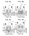
- FIG. 6A is a plan view illustrating one example of the hole of the first member illustrated in FIG. 3 ;
- FIG. 6B is a plan view illustrating another example of the hole of the first member illustrated in FIG. 3 ;
- FIG. 7A is a drawing of a longitudinal section to describe Embodiment 4 of the joining method of the present invention, and describes a laminating step thereof;
- FIG. 7B is a drawing of a longitudinal section to describe Embodiment 4 of the joining method of the present invention, and describes a softening-melting step thereof;
- FIG. 7C is a drawing of a longitudinal section to describe Embodiment 4 of the joining method of the present invention, and describes an introducing step thereof;
- FIG. 7D is a drawing of a longitudinal section to describe Embodiment 4 of the joining method of the present invention, and describes a curing step thereof;
- FIG. 8A is a drawing of a longitudinal section to describe Modification of the joining method illustrated in FIG. 7 , and describes a laminating step thereof;
- FIG. 8B is a drawing of a longitudinal section to describe Modification of the joining method illustrated in FIG. 7 , and describes a softening-melting step thereof;
- FIG. 8C is a drawing of a longitudinal section to describe Modification of the joining method illustrated in FIG. 7 , and describes an introducing step thereof;
- FIG. 8D is a drawing of a longitudinal section to describe Modification of the joining method illustrated in FIG. 7 , and describes a curing step thereof;
- FIG. 9 is a drawing of a longitudinal section illustrating another example of a hole of a first member illustrated in FIG. 7 ;
- FIG. 10 is a drawing of a longitudinal section illustrating another example of a hole of a first member illustrated in FIG. 8 ;
- FIG. 11A is a drawing of a longitudinal section to describe Embodiment 5 of the joining method of the present invention, and describes a laminating step thereof;
- FIG. 11B is a drawing of a longitudinal section to describe Embodiment 5 of the joining method of the present invention, and describes a softening-melting step thereof;
- FIG. 11C is a drawing of a longitudinal section to describe Embodiment 5 of the joining method of the present invention, and describes an introducing step thereof;
- FIG. 11D is a drawing of a longitudinal section to describe Embodiment 5 of the joining method of the present invention, and describes a curing step thereof;
- FIG. 12A is a drawing of a longitudinal section to describe Modification of the joining method illustrated in FIG. 11 , and describes a laminating step thereof;
- FIG. 12B is a drawing of a longitudinal section to describe Modification of the joining method illustrated in FIG. 11 , and describes a softening-melting step thereof;
- FIG. 12C is a drawing of a longitudinal section to describe Modification of the joining method illustrated in FIG. 11 , and describes an introducing step thereof;
- FIG. 12D is a drawing of a longitudinal section to describe Modification of the joining method illustrated in FIG. 11 , and describes a curing step thereof;
- FIG. 13A is a drawing of a longitudinal section to describe Embodiment 6 of the joining method of the present invention, and describes a laminating step thereof;
- FIG. 13B is a drawing of a longitudinal section to describe Embodiment 6 of the joining method of the present invention, and describes a softening-melting step thereof;
- FIG. 13C is a drawing of a longitudinal section to describe Embodiment 6 of the joining method of the present invention, and describes an introducing step thereof;
- FIG. 13D is a drawing of a longitudinal section to describe Embodiment 6 of the joining method of the present invention, and describes a curing step thereof;
- FIG. 14A is a drawing of a longitudinal section illustrating a joining state between a first member and a second member in a case where the second member is made of a fiber reinforced resin material;
- FIG. 14B is a drawing of a longitudinal section illustrating a joining state between a first member and a second member in a case where the second member is made of a fiber reinforced resin material;
- FIG. 14C is a drawing of a longitudinal section illustrating a joining state between a first member and a second member in a case where the second member is made of a fiber reinforced resin material;
- FIG. 14D is a drawing of a longitudinal section illustrating a joining state between a first member and a second member in a case where the second member is made of a fiber reinforced resin material.
- FIG. 1 is a drawing of a longitudinal section to describe Embodiment 1 of the joining method of the present invention: FIG. 1A is a view to describe a laminating step thereof; FIG. 1B and FIG. 1C are views to describe a softening-melting/introducing step thereof; and FIG. 1D is a view to describe a curing step thereof.
- the joining method according to Embodiment 1 of the present invention is performed by use of a joining apparatus including a heater.
- the joining apparatus 30 mainly includes a heater 31 , and a clamping member 34 , as illustrated in FIG. 1A , and also includes support members that support these members, and so on, although not illustrated in FIG. 1A .
- the clamping member 34 has a tubular shape (e.g., a generally cylindrical shape) having a hollow, for example, and the heater 31 as heating means is inserted into the hollow.
- the clamping member 34 is supported by the support member (not shown) via a spring (not shown), for example, so as to press a workpiece (a second member 2 ) from its one surface (a top face in FIG. 1A ).
- the heater 31 and the clamping member 34 configured as such include an abutting surface 31 a and an abutting surface 34 a , respectively.
- the abutting surface 34 a of the clamping member 34 is moved by a drive mechanism (not shown) in an axis-Xr direction so as to abut with the one surface of the workpiece.
- the abutting surface 31 a of the heater 31 is moved by a drive mechanism (not shown) in the axis-Xr direction to a slightly upper side of the one surface of the workpiece.
- Embodiment 1 specifically describes a method in which a generally flat-shaped first member 1 made of a metal member, a resin member, a wood material, or the like having a generally recessed hole 3 that is opened on one surface (a top face in FIG. 1 ) 1 a is joined to a generally flat-shaped second member 2 made of a metal member, a resin member, or the like including a material of which a melting temperature is lower than that of a constituent material of the first member 1 .
- the joining method according to Embodiment 1 mainly includes a laminating step, a softening-melting/introducing step, and a curing step.
- the second member 2 is laminated on the first member 1 so as to cover an opening 3 a of the hole 3 provided in the first member 1 , as illustrated in FIG. 1A .
- the joining apparatus 30 is positioned and disposed on a top face 2 a of the second member 2 , so that the opening 3 a of the hole 3 of the first member 1 is placed on the axis Xr, in other words, the heater 31 is placed above the opening 3 a of the hole 3 of the first member 1 and one surface (the top face in FIG. 1 ) 2 a of the second member 2 abuts with the abutting surface 34 a of the clamping member 34 .
- the first member 1 is supported by a support member (not shown), and the second member 2 is supported in such a manner that the second member 2 is pressed against the first member 1 by the clamping member 34 .
- a constituent material of the second member 2 particularly a constituent material of that part of the second member 2 which is placed on the hole 3 of the first member 1 is softened or melted by use of heat of the heater 31 , as illustrated in FIG. 1B .
- a softened or melted constituent material 2 c of the second member 2 is introduced into the hole 3 through the opening 3 a by gravity (by its own weight), as illustrated in FIG. 1C .
- the softened or melted constituent material 2 c of the second member 2 (that constituent material of the second member 2 which is introduced into the hole 3 of the first member 1 and that constituent material of the second member 2 which remains on the top face 1 a of the first member 1 around the hole 3 ) is cured so that the first member 1 is integrated with the second member 2 , and then, the joining apparatus 30 is removed from the top face 2 a of the second member 2 .
- the joining method of Embodiment 1 is performed such that: the second member 2 is laminated on the first member 1 so as to cover the opening 3 a of the hole 3 provided in the first member 1 ; the constituent material of that part of the second member 2 which is placed on the opening 3 a of the hole 3 is locally softened or melted by use of heat of the heater 31 ; the softened or melted constituent material 2 c of the second member 2 is introduced into the hole 3 of the first member 1 through the opening 3 a of the hole 3 ; and the constituent material 2 c of the second member 2 thus introduced into the hole 3 is cured.
- This makes it possible to easily join the first member 1 and the second member 2 , which are different type of members, at low cost.
- FIG. 2 is a drawing of a longitudinal section to describe Embodiment 2 of the joining method of the present invention: FIG. 2A is a view to describe a laminating step thereof; FIG. 2B and FIG. 2C are views to describe a softening-melting/introducing step thereof; and FIG. 2D is a view to describe a curing step thereof.
- the joining method according to Embodiment 2 of the present invention is performed by use of a single acting friction stir welding apparatus as an example of a friction stir welding apparatus.
- a single acting friction stir welding apparatus as an example of a friction stir welding apparatus.
- the following generally describes an example of the single acting friction stir welding (FSW) apparatus used in the joining method according to Embodiment 2, with reference to FIG. 2A .
- the FSW apparatus 40 used in the joining method according to Embodiment 2 mainly includes a rotating tool portion 41 and a clamping member 44 , and also includes support members that support these members, a drive mechanism that drives the rotating tool portion 41 , and so on, although not illustrated in FIG. 2A .
- the clamping member 44 is fixed to the support member (not shown) via a spring 43 .
- the rotating tool portion 41 has a generally circular column shape.
- the rotating tool portion 41 is configured to be rotated by the drive mechanism (not shown) around an axis (a rotating axis) Xr and to be slidable relative to the clamping member 44 along a direction of a broken-line arrow Q 1 , that is, an axis-Xr direction (an up-down direction in FIG. 2A ).
- the clamping member 44 is provided outside the rotating tool portion 41 and has a generally cylindrical shape having a hollow.
- the rotating tool portion 41 is inserted into the hollow.
- the clamping member 44 is supported by the support member (not shown) via the spring 43 , so as to press a workpiece (a second member 2 ) from one surface (a top face in FIG. 2A ) thereof.
- the clamping member 44 is configured to be movable in a direction of a broken-line arrow Q 3 , that is, the axis-Xr direction in a state where the clamping member 44 is biased toward the workpiece.
- the rotating tool portion 41 and the clamping member 44 configured as such include abutting surfaces 41 a , 44 a , respectively.
- the abutting surfaces 41 a , 44 a are moved by the drive mechanism (not shown) in the axis-Xr direction so as to abut with the one surface of the workpiece.
- a specific configuration of the single acting friction stir welding (FSW) apparatus 40 in the present embodiment is not limited to the above configuration, and may include other members, which are not described in terms of the FSW apparatus 40 .
- Embodiment 2 specifically describes a method for joining a first member 1 and a second member 2 , which are similar to those in Embodiment 1.
- the joining method according to Embodiment 2 mainly includes a laminating step, a softening-melting/introducing step, and a curing step.
- the second member 2 is laminated on the first member 1 so as to cover an opening 3 a of a hole 3 provided in the first member 1 , as illustrated in FIG. 2A .
- the FSW apparatus 40 is positioned and disposed on a top face 2 a of the second member 2 , so that the opening 3 a of the hole 3 of the first member 1 is placed on the axis Xr, in other words, the rotating tool portion (a pin member) 41 is placed above the opening 3 a of the hole 3 of the first member 1 and one surface (the top face in FIG.
- first member 1 is supported by a support member (not shown), and the second member 2 is supported in such a manner that the second member 2 is pressed against the first member 1 by the clamping member 44 .
- the rotating tool portion 41 is rotated around the axis Xr, so that a constituent material of the second member 2 , particularly a constituent material of that part of the second member 2 which is placed on the hole 3 of the first member 1 is softened or melted by use of frictional heat generated between the abutting surface 41 a of the rotating tool portion 41 and the top face 2 a of the second member 2 , as illustrated in FIG. 2B .
- the softened or melted constituent material 2 c of the second member 2 is introduced into the hole 3 through the opening 3 a by gravity (by its own weight), as illustrated in FIG. 2C .
- the softened or melted constituent material 2 c of the second member 2 may be introduced into the hole 3 in such a manner that the rotating tool portion 41 is moved downward along the axis-Xr direction so that the constituent material 2 c of that part of the second member 2 which is below the rotating tool portion 41 is partially pushed into the hole 3 of the first member 1 .
- the softened or melted constituent material 2 c of the second member 2 (that constituent material of the second member 2 which is introduced into the hole 3 of the first member 1 and that constituent material of the second member 2 which remains on a top face 1 a of the first member 1 around the hole 3 ) is cured so that the first member 1 is integrated with the second member 2 , and then, the FSW apparatus 40 is removed from the top face 2 a of the second member 2 .
- the joining method of Embodiment 2 is performed such that: the second member 2 is laminated on the first member 1 so as to cover the opening 3 a of the hole 3 provided in the first member 1 ; the constituent material of that part of the second member 2 which is placed on the opening 3 a of the hole 3 is locally softened or melted by use of frictional heat; the softened or melted constituent material 2 c of the second member 2 is introduced into the hole 3 through the opening 3 a of the hole 3 of the first member 1 ; and the constituent material 2 c of the second member 2 thus introduced into the hole 3 is cured.
- This makes it possible to easily join the first member 1 and the second member 2 , which are different type of members, at low cost.
- the constituent material of that part of the second member 2 which is placed on the opening 3 a of the hole 3 is softened or melted by use of frictional heat, thereby yielding such an advantage that the constituent material of the second member 2 can be more surely softened and melted.
- FIG. 3 is a drawing of a longitudinal section to describe Embodiment 3 of the joining method of the present invention: FIG. 3A is a view to describe a laminating step thereof; FIG. 3B is a view to describe a softening-melting step thereof; FIG. 3C is a view to describe an introducing step thereof and FIG. 3D is a view to describe a curing step thereof
- the joining method according to Embodiment 3 of the present invention is performed by use of a double acting friction stir welding apparatus as a typical example of a friction stir welding apparatus.
- a double acting friction stir welding apparatus as a typical example of a friction stir welding apparatus.
- the following generally describes a typical example of the double acting friction stir welding (FSW) apparatus used in the joining method according to Embodiment 3, with reference to FIG. 3A .
- the FSW apparatus 50 used in the joining method according to Embodiment 3 mainly includes a rotating tool portion 51 and a clamping member 54 , and also includes support members that support these members, a drive mechanism that drives the rotating tool portion 51 , and so on, although not illustrated in FIG. 3A .
- the clamping member 54 is fixed to the support member (not shown) via a spring 53 .
- the rotating tool portion 51 is constituted by a pin member 11 and a shoulder member 12 .
- the pin member 11 has a generally circular column shape.
- the pin member 11 is configured to be rotated by the drive mechanism (not shown) around an axis (a rotating axis) Xr and to be movable relative to the shoulder member 12 along a direction of a broken-line arrow P 1 , that is, an axis-Xr direction (an up-down direction in FIG. 3A ).
- the shoulder member 12 has a generally cylindrical shape having a hollow. The pin member 11 is inserted into the hollow, and the shoulder member 12 is supported by a support member (not shown) outside the pin member 11 so as to surround the pin member 11 .
- the shoulder member 12 is configured to be rotated by the drive mechanism (not shown) around the axis Xr, which is the same as the pin member 11 , and to be movable relative to the pin member 11 (in the same direction as the pin member 11 or an opposite direction to the pin member 11 ) along a direction of a broken-line arrow P 2 direction, that is, along the axis-Xr direction. Accordingly, the pin member 11 and the shoulder member 12 constituting the rotating tool portion 51 are configured to be rotated integrally around the axis Xr and to be movable relative to each other (in the same direction or in opposite directions) along the axis-Xr direction.
- the clamping member 54 is provided outside the shoulder member 12 of the rotating tool portion 51 and has a generally cylindrical shape having a hollow, similarly to the shoulder member 12 .
- the shoulder member 12 is inserted into the hollow. Accordingly, the shoulder member 12 having a generally cylindrical shape is placed on an outer periphery of the pin member 11 , and the clamping member 54 having a generally cylindrical shape is placed on an outer periphery of the shoulder member 12 .
- the clamping member 54 , the shoulder member 12 , and the pin member 11 have a nested structure in which they are placed coaxially.
- the clamping member 54 is supported by the support member (not shown) via the spring 53 , so as to press a workpiece (a second member 2 ) from one surface (a top face in FIG.
- the clamping member 54 is configured to be movable in a direction of a broken-line arrow P 3 , that is, the axis-Xr direction in a state where the clamping member 54 is biased toward the workpiece.
- the pin member 11 and the shoulder member 12 constituting the rotating tool portion 51 , and the clamping member 54 include an abutting surface 11 a , an abutting surface 12 a , and an abutting surface 54 a , respectively.
- the abutting surfaces 11 a , 12 a , and 54 a are moved by the drive mechanisms (not shown) in the axis-Xr direction so as to abut with the one surface of the workpiece.
- the concrete configuration of the rotating tool portion 51 in the present embodiment is not limited to the configuration described above, and a well-known configuration in the field of FSW can be used appropriately.
- the friction stir welding apparatus is not limited to the FSW apparatus 50 having the above configuration, and may have a configuration in which the clamping member 54 is provided outside the pin member 11 , or may include other members, which are not described in terms of the FSW apparatus 50 .
- Embodiment 3 specifically describes a method for joining a first member 1 and a second member 2 , which are similar to those in Embodiments 1, 2.
- the joining method according to Embodiment 3 mainly includes a laminating step, a softening-melting step, an introducing step, and a curing step.
- the second member 2 is laminated on the first member 1 so as to cover an opening 3 a of a hole 3 provided in the first member 1 , as illustrated in FIG. 3A .
- the FSW apparatus 50 is positioned and disposed on a top face 2 a of the second member 2 , so that the opening 3 a of the hole 3 of the first member 1 is placed on the axis Xr, in other words, the pin member 11 of the rotating tool portion 51 is placed above the opening 3 a of the hole 3 of the first member 1 and one surface (the top face in FIG.
- the pin member 11 and the shoulder member 12 are rotated integrally around the axis Xr, so that a constituent material of the second member 2 , particularly a constituent material of that part of the second member 2 which is placed on the hole 3 of the first member 1 is softened or melted by use of frictional heat generated between the abutting surfaces 11 a , 12 a of the pin member 11 and the shoulder member 12 and the top face 2 a of the second member 2 , as illustrated in FIG. 3B .
- the shoulder member 12 is moved downward by a predetermined amount along the axis-Xr direction and the pin member 11 is moved upward along the axis-Xr direction, so that a softened or melted constituent material 2 c of the second member 2 is led below the pin member 11 .
- the shoulder member 12 is moved upward by a predetermined amount along the axis-Xr direction according to a volume of the softened or melted constituent material 2 c of the second member 2 , a volume of the hole 3 of the first member 1 , and so on, for example, so that the abutting surface 11 a of the pin member 11 and the abutting surface 12 a of the shoulder member 12 are placed at generally the same height.
- the softened or melted constituent material 2 c of the second member 2 in the softening-melting step (that constituent material of the second member 2 which is introduced into the hole 3 of the first member 1 and that constituent material of the second member 2 which remains on the top face 1 a of the first member 1 around the hole 3 ) is cured so that the first member 1 is integrated with the second member 2 , and then, the FSW apparatus 50 is removed from the top face 2 a of the second member 2 .
- the joining method of Embodiment 3 is performed such that: the second member 2 is laminated on the first member 1 so as to cover the opening 3 a of the hole 3 provided in the first member 1 ; the constituent material of that part of the second member 2 which is placed on the opening 3 a of the hole 3 is locally softened or melted by use of frictional heat; the softened or melted constituent material 2 c of the second member 2 is introduced into the hole 3 of the first member 1 through the opening 3 a of the hole 3 ; and the constituent material 2 c of the second member 2 thus introduced into the hole 3 is cured.
- This makes it possible to easily join the first member 1 and the second member 2 , which are different type of members, at low cost.
- a shape (a longitudinal sectional shape and a cross sectional shape) of the hole provided in the first member can be designed appropriately according to joining strength between the first member and the second member, and so on.
- the hole 3 provided in the first member 1 is continuously reduced in diameter toward the opening 3 a on the one surface (the top face), so that a sectional area of the hole 3 along a direction perpendicular to a laminating direction (the axis-Xr direction) is minimized at the opening 3 a .
- a portion cured in the hole 3 of the first member 1 is broken from the second member 2 due to a taper angle or the like of the hole 3 , so that the second member 2 may be detached from the first member 1 or a portion cured in the hole 3 of the first member 1 may be slipped off from the hole 3 due to elasticity or the like of the second member 2 .
- a hole 3 ′ provided in a first member 1 ′ may be formed so as to be reduced in diameter in a stepped manner toward an opening 3 a ′ on one surface (a top face).
- the hole provided in the first member may be formed by appropriately combining a reduced diameter portion reduced in diameter continuously or in a stepped manner toward the opening on the one surface (the top face), a linear portion having the same inside diameter in a thickness direction (a laminating direction) of the first member, and an enlarged diameter portion enlarged in diameter continuously or in a stepped manner toward the opening on the one surface (the top face).
- a reduced diameter portion 4 ′′ reduced in diameter continuously or in a stepped manner toward an opening 3 a ′′ on one surface (a top face) 1 a ′′ may be provided on a lower end side of a hole 3 ′′ provided in a first member 1 ′′ (a reduced diameter portion reduced in diameter continuously in FIG. 5 ), and a linear portion 5 ′′ having the same inside diameter along a thickness direction of the first member 1 ′′ may be provided on its upper end side.
- a shape, in a plan view, of the opening of the hole provided in the first member may be a generally circular shape (see FIG. 6A ), a generally elliptical shape, a generally elongated hole shape (see FIG. 6B ), a polygonal shape such as a square shape, or the like.
- FIG. 7 is a drawing of a longitudinal section to describe Embodiment 4 of the joining method of the present invention: FIG. 7A is a view to describe a laminating step thereof; FIG. 7B is a view to describe a softening-melting step thereof; FIG. 7C is a view to describe an introducing step thereof; and FIG. 7D is a view to describe a curing step thereof.
- the joining method according to Embodiment 4 is performed by use of the FSW apparatus 50 used in the joining method according to Embodiment 3 described above.
- Embodiment 4 specifically describes a method in which a generally flat-shaped first member 1 A made of a metal member, a resin member, a wood material, or the like having a hole (through hole) 3 A formed from one surface (a top face in FIG. 7 ) 1 a A toward the other surface (a bottom face in FIG. 7 ) 1 b A is joined to a generally flat-shaped second member 2 A made of a metal member, a resin member, or the like including a material of which a melting temperature is lower than that of a constituent material of the first member 1 A.
- the joining method according to Embodiment 4 mainly includes a laminating step, a softening-melting step, an introducing step, and a curing step.
- the second member 2 A is laminated on the first member 1 A so as to cover an opening 3 a A on a top face 1 a A of the hole 3 A provided in the first member 1 A, as illustrated in FIG. 7A .
- the FSW apparatus 50 is positioned and disposed on a top face 2 a A of the second member 2 , so that the opening 3 a A of the hole 3 A of the first member 1 A is placed on an axis Xr, in other words, the pin member 11 of the rotating tool portion 51 is placed above the opening 3 a A of the hole 3 A of the first member 1 A and one surface (the top face in FIG.
- a generally flat-shaped backing member (also referred to as a back tool) 55 is positioned and disposed so as to cover an opening 3 b A on a bottom face 1 b A of the hole 3 A of the first member 1 A.
- the backing member 55 is supported by a support member (not shown), and the second member 2 A and the first member 1 A are supported in such a manner that the second member 2 A and the first member 1 A are pressed against the backing member 55 by the clamping member 54 .
- the softening-melting step (see FIG. 7B ), the introducing step (see FIG. 7C ), and the curing step (see FIG. 7D ) similar to those steps in the joining method according to Embodiment 3 are performed, so that the first member 1 A and the second member 2 A are joined to each other so as to be integrated with each other.
- the joining method of Embodiment 4 is performed such that: the second member 2 A is laminated on the first member 1 A so as to cover the opening 3 a A on the one surface 1 a A of the hole 3 A provided in the first member 1 A; the constituent material of that part of the second member 2 A which is placed on the opening 3 a A of the hole 3 A is locally softened or melted by use of frictional heat; a softened or melted constituent material 2 c A of the second member 2 A is introduced into the hole 3 A through the opening 3 a A of the hole 3 A of the first member 1 A; and the constituent material 2 c A of the second member 2 A thus introduced into the hole 3 A is cured.
- This makes it possible to easily join the first member 1 A and the second member 2 A, which are different type of members, at low cost.
- the hole 3 A of the first member 1 A is formed so as to penetrate from the one surface 1 a A to the other surface 1 b A. Accordingly, in the introducing step, the softened or melted constituent material 2 c A of the second member 2 A can be introduced into the hole 3 A of the first member 1 A while gas such as air and the like existing in the hole 3 A of the first member 1 A is being exhausted through the opening 3 b A on the other surface 1 b A of the hole 3 A. This makes it possible to more tightly and strongly join the first member 1 A to the second member 2 A, thereby yielding such an advantage that joining strength between the first member 1 A and the second member 2 A can be increased more effectively.
- a shape (a longitudinal sectional shape and a cross sectional shape) of the hole provided in the first member can be designed appropriately according to the joining strength between the first member and the second member, and so on in the joining method of Embodiment 4.
- a hole 3 A′ provided in a first member 1 A′ may be formed so as to be reduced in diameter in a stepped manner from an opening 3 b A′ on the other surface (bottom face) 1 b A′ toward an opening 3 a A′ on one surface (top face) 1 a A′.
- the hole provided in the first member may be formed by appropriately combining a reduced diameter portion reduced in diameter continuously or in a stepped manner toward the opening on the one surface (the top face), a linear portion having the same inside diameter in the thickness direction (a laminating direction) of the first member, an enlarged diameter portion enlarged in diameter continuously or in a stepped manner toward the opening on the one surface (the top face).
- a reduced diameter portion 4 A′′ (a reduced diameter portion reduced in diameter continuously in FIG.
- annular groove 5 A′′′ hollowed toward one surface (a top face) 1 a A“′ may be formed in part of that hole 3 A”′ of a first member 1 A′′′ which is reduced in diameter in a stepped manner (in an outer peripheral portion of the hole 3 A′′′ in FIG. 10 ), and a softened or melted constituent material of a second member may be also introduced into the groove 5 A′′′ in the above described introducing step, and then cured.
- a shape, in a plan view, of the opening of the hole provided in the first member may be a generally circular shape, a generally elliptical shape, a generally elongated hole shape, a polygonal shape such as a square shape, or the like.
- FIG. 11 is a drawing of a longitudinal section to describe Embodiment 5 of the joining method of the present invention: FIG. 11A is a view to describe a laminating step thereof; FIG. 11B is a view to describe a softening-melting step thereof; FIG. 11C is a view to describe an introducing step thereof; and FIG. 11D is a view to describe a curing step thereof.
- the joining method according to Embodiment 5 is performed by use of the FSW apparatus 50 used in the joining method according to Embodiments 3, 4 described above.
- Embodiment 5 specifically describes a method in which a generally flat-shaped first member 1 B made of a metal member, a resin member, a wood material, or the like having a linear hole (through hole) 3 B formed from one surface (a top face in FIG. 11 ) 1 a B toward the other surface (a bottom face in FIG. 11 ) 1 b B is joined to a generally flat-shaped second member 2 B made of a metal member, a resin member, or the like including a material of which a melting temperature is lower than that of a constituent material of the first member 1 B.
- the joining method according to Embodiment 5 mainly includes a laminating step, a softening-melting step, an introducing step, and a curing step.
- the second member 2 B is laminated on the first member 1 B so as to cover an opening 3 a B of the hole 3 B provided in the first member 1 B which opening 3 a B is formed on the top face 1 a B, as illustrated in FIG. 11A .
- the FSW apparatus 50 is positioned and disposed on a top face 2 a B of the second member 2 B, so that the opening 3 a B of the hole 3 B of the first member 1 B is placed on an axis Xr, in other words, the pin member 11 of the rotating tool portion 51 is placed above the opening 3 a B of the hole 3 B of the first member 1 B and one surface (the top face in FIG.
- a backing member (also referred to as a back tool) 55 having a recessed depression 55 a having an inside diameter or a cross sectional area larger than a diameter or a cross sectional area (a sectional area of the hole 3 B along a direction perpendicular to a laminating direction) of the hole 3 B of the first member 1 B is prepared in advance.
- the backing member 55 is positioned and disposed so that the backing member 55 covers an opening 3 b B of the hole 3 B of the first member 1 B which opening 3 b B is formed on the bottom face 1 b B, and the depression 55 a of the backing member 55 communicates with the hole 3 B of the first member 1 B.
- the backing member 55 is supported by a support member (not shown), and the second member 2 B and the first member 1 B are supported in such a manner that the second member 2 B and the first member 1 B are pressed against the backing member 55 by the clamping member 54 .
- the softening-melting step (see FIG. 11B ) similar to the softening-melting step in the joining methods according to Embodiments 3, 4 is performed.
- the pin member 11 is moved downward along the axis-Xr direction, so that that constituent material 2 c B of the second member 2 B which is led below the pin member 11 is partially pushed into the hole 3 B of the first member 1 B and the depression 55 a of the backing member 55 .
- the shoulder member 12 is moved upward by a predetermined amount along the axis-Xr direction according to a volume of a softened or melted constituent material 2 c B of the second member 2 B, volumes of the hole 3 B of the first member 1 B and the depression 55 a of the backing member 55 , and so on, for example, so that the abutting surface 11 a of the pin member 11 and the abutting surface 12 a of the shoulder member 12 are placed at generally the same height.
- the softened or melted constituent material 2 c B of the second member 2 B in the softening-melting step (that constituent material of the second member 2 B which is introduced into the hole 3 B of the first member 1 B and the depression 55 a of the backing member 55 and that constituent material of the second member 2 B which remains on the top face 1 a B of the first member 1 B around the hole 3 B) is cured so that the first member 1 B is integrated with the second member 2 B.
- the FSW apparatus 50 is removed from the top face 2 a B of the second member 2 B and the backing member 55 is removed from the bottom face 1 b B of the first member 1 B.
- the joining method of Embodiment 5 is performed in such a manner that: the second member 2 B is laminated on the first member 1 B so as to cover the opening 3 a B, on the one surface 1 a B, of the linear hole (through hole) 3 B provided in the first member 1 B; the backing member 55 is disposed on the other surface 1 b B of the first member 1 B so that the backing member 55 covers the opening 3 b B, on the bottom face 1 b B, of the hole 3 B of the first member 1 B and the depression 55 a of the backing member 55 communicates with the hole 3 B of the first member 1 B; the constituent material of that part of the second member 2 B which is placed on the opening 3 a B of the hole 3 B is locally softened or melted by use of frictional heat; the softened or melted constituent material 2 c B of the second member 2 B is introduced into the hole 3 B of the first member 1 B and the depression 55 a of the backing member 55 through the opening 3 a B of the hole 3 B; and the constituent material 2 c
- the linear hole (through hole) 3 B is formed in advance in the first member 1 B.
- the hole 3 provided in the first member 1 is reduced in diameter continuously toward the opening 3 a on the one surface (the top face), so that the sectional area of the hole 3 along the direction perpendicular to the laminating direction (the axis-Xr direction) is minimized at the opening 3 a .
- the opening 3 a of the hole 3 may be deformed in the introducing step or the like illustrated in FIG. 3C .
- the hole (through hole) 3 B provided in the first member 1 B has a linear shape. Accordingly, it is possible to restrain deformation of the opening 3 a B of the hole 3 B in the introducing step or the like, thereby yielding such an advantage that the first member 1 B can be surely joined to the second member 2 B.
- a shape (a longitudinal sectional shape and a cross sectional shape) of the hole provided in the first member can be designed appropriately according to joining strength between the first member and the second member, and so on in the joining method of Embodiment 5.
- a shape of the depression formed in the backing member disposed on the bottom face of the first member can be designed appropriately, provided that the backing member can be easily removed from the bottom face of the first member after the curing step, for example.
- annular groove 5 B′ formed around the axis Xr, for example, and communicating with the depression 55 a of the backing member 55 may be formed in part of a bottom face 1 b B′ of a first member 1 B′ (corresponding to an outer peripheral portion of the depression 55 a of the backing member 55 in FIG. 12 ), and a softened or melted constituent material of a second member may be also introduced into the groove 5 B′ in the introducing step, and then cured.
- Embodiments 1 to 5 deal with a configuration in which the first member and the second member having a generally flat shape are joined to each other.
- a shape of each of the members as a joining object can be set appropriately.
- the flat-shaped second member is used like Embodiments 1 to 5
- a thickness in the part of the second member is decreased at the time of curing the softened or melted constituent material of the second member so as to join the first member to the second member.
- the second member includes an extra amount of the material corresponding to the part introduced into the hole or the like of the first member in advance, it is considered that the decrease in the thickness of the second member at the time of joining the first member to the second member can be restrained.
- FIG. 13 is a drawing of a longitudinal section to describe Embodiment 6 of the joining method of the present invention: FIG. 13A is a view to describe a laminating step thereof; FIG. 13B is a view to describe a softening-melting step thereof; FIG. 13C is a view to describe an introducing step thereof; and FIG. 13D is a view to describe a curing step thereof.
- the joining method according to Embodiment 6 is performed by use of the FSW apparatus 50 used in the joining methods according to Embodiments 3 to 5 described above.
- Embodiment 6 specifically describes a method in which a generally flat-shaped first member 1 C made of a metal member, a resin member, a wood material, or the like having a hole 3 C formed from one surface (a top face in FIG. 13 ) 1 a C toward the other surface (a bottom face in FIG. 13 ) 1 b C is joined to a second member 2 C made of a metal member, a resin member, or the like including a material of which a melting temperature is lower than that of a constituent material of the first member 1 C, the second member 2 C having a projection 2 d C on one surface (a top face in FIG. 13 ) 2 a C thereof.
- the joining method according to Embodiment 6 mainly includes a laminating step, a softening-melting step, an introducing step, and a curing step.
- the second member 2 C is laminated on the first member 1 C so that the second member 2 C covers an opening 3 a C, on the top face 1 a C, of the hole 3 C provided in the first member 1 C and the projection 2 d C of the second member 2 C is placed generally above the hole 3 C, as illustrated in FIG. 13A .
- the projection 2 d C of the second member 2 C is formed so as to be placed inside the clamping member 54 of the FSW apparatus 50 . More specifically, the projection 2 d C is formed so that its top face abuts with the abutting surfaces 11 a , 12 a of the pin member 11 and the shoulder member 12 of the FSW apparatus 50 .
- the projection 2 d C of the second member 2 C is formed so that its volume is generally the same as a volume of the hole 3 C provided in the first member 1 C.
- the FSW apparatus 50 is positioned and disposed on the top face 2 a C of the second member 2 C, so that the opening 3 a C of the hole 3 C of the first member 1 C is placed on an axis Xr, in other words, the pin member 11 of the rotating tool portion 51 is placed above the opening 3 a C of the hole 3 C of the first member 1 C and the one surface 2 a C of the second member 2 C abuts with the abutting surface 54 a of the clamping member 54 and a top face of the projection 2 d C of the second member 2 C abuts with the abutting surfaces 11 a , 12 a of the pin member 11 and the shoulder member 12 .
- a generally flat-shaped backing member 55 is positioned and disposed so as to cover the opening 3 b C, on the bottom face 1 b C, of the hole 3 C of the first member 1 C.
- the backing member 55 is supported by a support member (not shown), and the second member 2 C and the first member 1 C are supported in such a manner that the second member 2 C and the first member 1 C are pressed against the backing member 55 by the clamping member 54 .
- the pin member 11 and the shoulder member 12 are integrally rotated around the axis Xr, so that a constituent material of the second member 2 C including the projection 2 d C is softened or melted by use of frictional heat generated between the abutting surfaces 11 a , 12 a of the pin member 11 and the shoulder member 12 and the top face of the projection 2 d C of the second member 2 C, as illustrated in FIG. 13B .
- the shoulder member 12 is moved downward by a predetermined amount along the axis-Xr direction and the pin member 11 is moved upward along the axis-Xr direction, so that a softened or melted constituent material 2 c C of the second member 2 C is led below the pin member 11 .
- the introducing step (see FIG. 13C ), and the curing step (see FIG. 13D ) similar to those steps in the joining method according to Embodiment 4 are performed, so that the first member 1 C and the second member 2 C are joined to each other so as to be integrated with each other.
- the joining method of Embodiment 6 is performed such that: the projection 2 d C having generally the same volume as the hole 3 C of the first member 1 C is formed on the one surface (a surface opposite to the abutting surface with the first member 1 C) 2 a C of the second member 2 C is formed; the constituent material of the second member 2 C including the projection 2 d C is softened or melted in the softening-melting step; and the constituent material of the second member 2 C is introduced into the hole 3 C and then cured.
- the joining methods according to Embodiments 1 to 6 do not have a limit in types of the members as the joining object in particular.
- the inventor(s) have confirmed that it is preferable that the second member be made of a fiber reinforced resin member configured such that a fiber material is mixed in resin (matrix resin) of which a melting temperature is lower than the constituent material of the first member.
- the second member is made of a fiber reinforced resin member configured such that a fiber material is mixed in resin (matrix resin) of which a melting temperature is lower than the constituent material of the first member
- the fiber material included in the second member is oriented in a laminating direction (that is, a direction perpendicular to a lamination plane between the first member and the second member) in the vicinity of the opening of the hole (a region R in FIGS. 14A to 14D ) in the introducing step, as illustrated in FIGS. 14A to 14D .
- the matrix resin is cured in that state, thereby making it possible to effectively increase the joining strength between the first member and the second member.
- the fiber material contained in the second member is oriented surely in the laminating direction in the vicinity of the opening of the hole (that is, the fiber material oriented in the laminating direction is increased), thereby making it possible to more effectively increase the joining strength between the first member and the second member.
- the resin (matrix resin) constituting the second member may be thermo setting resin or thermo plastic resin.
- the thermo setting resin include epoxy resin, phenolic resin, melamine resin, and the like.
- the thermo plastic resin may be, for example, one or more admixtures of polypropylene (PP), polyethylene (PE), polystyrene (PS), AS resin, ABS resin, polyvinylchloride (PVC), methacrylic resin, polyamide (PA), polyester, polyacetal (POM), polycarbonate (PC), polyethylene terephthalate (PET), polybutylene terephthalate (PBT), polymethyl methacrylate (PMMA), polyvinylidene fluoride, polyphenylene oxide, polyphenylene sulfide, poly ether ether ketone, liquid crystal polymer, polyetherimide, polyethersulfone, polyamideimide, thermoplastic epoxy resin, and the like.
- PP polypropylene
- PE polyethylene
- PS polystyrene
- AS resin ABS resin
- PVC polyvinylchloride
- PA polyamide
- PET polyethylene terephthalate
- PBT polybutylene terephthalate
- PMMA poly
- copolymers mainly containing the thermo plastic resin, and graft resin and blend resin e.g., an ethylene-vinyl chloride copolymer, a vinyl acetate-ethylene copolymer, a vinyl acetate-vinyl chloride copolymer, an urethane-vinyl chloride copolymer, acrylic acid modified polypropylene, maleic acid modified polyethylene, and the like can be also introduced.
- the reinforcement fiber material constituting the second member may be, for example, one or more admixtures of ceramic fibers such as boron, alumina, silicon carbide, silicon nitride, and zirconia, inorganic fibers such as glass fiber and carbon fiber, metal fibers such as copper, steel, aluminum, and stainless, and organic fibers such as polyamide, polyester, and cellulose.
- ceramic fibers such as boron, alumina, silicon carbide, silicon nitride, and zirconia
- inorganic fibers such as glass fiber and carbon fiber
- metal fibers such as copper, steel, aluminum, and stainless
- organic fibers such as polyamide, polyester, and cellulose.
- the joining apparatus including a heater or the friction stir welding apparatus is used.
- any apparatus can be used provided that the constituent material of the second member can be softened or melted and the softened or melted constituent material of the second member can be introduced into the hole of the first member.
- the constituent material of the second member may be softened or melted by use of heat generation by supersonic vibration or by use of a hot plate heated in advance, or the like, instead of frictional heat.
- Embodiments 3 to 6 may be performed such that the second member is placed on the first member without using a pushdown force by an apparatus or the like, and the softened or melted constituent material of the second member is introduced into the hole of the first member only by gravity.
- Embodiments 1, 2 deal with a configuration in which the first member is joined to the second member through a plurality of steps including the laminating step, the softening-melting/introducing step, and the curing step
- Embodiments 3 to 6 deal with a configuration in which the first member is joined to the second member through a plurality of steps including the laminating step, the softening-melting step, the introducing step, and the curing step.
- the constituent material of the second member may be introduced into the hole of the first member through the opening of the hole while the constituent material is being softened or melted, and the constituent material of the second member may be cured in the hole of the first member while the constituent material is being introduced into the hole.
Landscapes
- Engineering & Computer Science (AREA)
- Mechanical Engineering (AREA)
- General Engineering & Computer Science (AREA)
- Physics & Mathematics (AREA)
- Thermal Sciences (AREA)
- Life Sciences & Earth Sciences (AREA)
- Wood Science & Technology (AREA)
- Chemical & Material Sciences (AREA)
- Composite Materials (AREA)
- Lining Or Joining Of Plastics Or The Like (AREA)
- Pressure Welding/Diffusion-Bonding (AREA)
Applications Claiming Priority (3)
| Application Number | Priority Date | Filing Date | Title |
|---|---|---|---|
| JP2014063611A JP5971273B2 (ja) | 2014-03-26 | 2014-03-26 | 接合方法 |
| JP2014-063611 | 2014-03-26 | ||
| PCT/IB2015/000466 WO2015145253A1 (en) | 2014-03-26 | 2015-03-26 | Joining method |
Publications (2)
| Publication Number | Publication Date |
|---|---|
| US20170136686A1 US20170136686A1 (en) | 2017-05-18 |
| US10173370B2 true US10173370B2 (en) | 2019-01-08 |
Family
ID=52991893
Family Applications (1)
| Application Number | Title | Priority Date | Filing Date |
|---|---|---|---|
| US15/128,565 Expired - Fee Related US10173370B2 (en) | 2014-03-26 | 2015-03-26 | Joining method |
Country Status (5)
| Country | Link |
|---|---|
| US (1) | US10173370B2 (ja) |
| EP (1) | EP3122487A1 (ja) |
| JP (1) | JP5971273B2 (ja) |
| TW (2) | TW201808588A (ja) |
| WO (1) | WO2015145253A1 (ja) |
Cited By (2)
| Publication number | Priority date | Publication date | Assignee | Title |
|---|---|---|---|---|
| US10406592B2 (en) * | 2014-01-16 | 2019-09-10 | Atlas Copco Ias Uk Limited | Method of riveting |
| EP4257263A4 (en) * | 2020-12-28 | 2024-05-15 | Kawasaki Jukogyo Kabushiki Kaisha | ASSEMBLY METHOD, ASSEMBLED BODY AND ASSEMBLY DEVICE |
Families Citing this family (16)
| Publication number | Priority date | Publication date | Assignee | Title |
|---|---|---|---|---|
| US11045851B2 (en) | 2013-03-22 | 2021-06-29 | Battelle Memorial Institute | Method for Forming Hollow Profile Non-Circular Extrusions Using Shear Assisted Processing and Extrusion (ShAPE) |
| US10695811B2 (en) | 2013-03-22 | 2020-06-30 | Battelle Memorial Institute | Functionally graded coatings and claddings |
| US11383280B2 (en) | 2013-03-22 | 2022-07-12 | Battelle Memorial Institute | Devices and methods for performing shear-assisted extrusion, extrusion feedstocks, extrusion processes, and methods for preparing metal sheets |
| JP6020501B2 (ja) * | 2014-03-27 | 2016-11-02 | トヨタ自動車株式会社 | 接合方法 |
| DE102015225821A1 (de) * | 2015-12-17 | 2017-06-22 | Volkswagen Aktiengesellschaft | Verfahren zum Verbinden von zwei Bauteilen |
| JP6650801B2 (ja) * | 2016-03-17 | 2020-02-19 | 川崎重工業株式会社 | 摩擦攪拌点接合方法及び摩擦攪拌点接合装置 |
| CN107404818B (zh) * | 2017-07-24 | 2019-08-09 | 广东长盈精密技术有限公司 | 一种壳体、一种壳体制作方法及一种移动终端 |
| JP6872241B2 (ja) * | 2017-08-31 | 2021-05-19 | エードス株式会社 | 回転摩擦溶接 |
| WO2019065301A1 (ja) * | 2017-09-29 | 2019-04-04 | 本田技研工業株式会社 | 樹脂接合体及びその製造方法 |
| JP7216551B2 (ja) * | 2019-01-07 | 2023-02-01 | 川崎重工業株式会社 | 摩擦攪拌点接合装置及び摩擦攪拌点接合方法 |
| JPWO2020179661A1 (ja) * | 2019-03-01 | 2020-09-10 | ||
| US11549532B1 (en) | 2019-09-06 | 2023-01-10 | Battelle Memorial Institute | Assemblies, riveted assemblies, methods for affixing substrates, and methods for mixing materials to form a metallurgical bond |
| CN110641027A (zh) * | 2019-09-26 | 2020-01-03 | 沈阳航空航天大学 | 用于长纤维增强热塑性复合材料与异种材料的点连接方法 |
| EP3815881A1 (de) * | 2019-10-28 | 2021-05-05 | Dyconex AG | Verbindung von kunststoffen mittels mikronieten |
| CN110936623B (zh) * | 2019-12-12 | 2020-10-20 | 惠州市华沃科技有限公司 | 一种金属胶带热复合工艺及热复合机 |
| WO2023043839A1 (en) | 2021-09-15 | 2023-03-23 | Battelle Memorial Institute | Shear-assisted extrusion assemblies and methods |
Citations (18)
| Publication number | Priority date | Publication date | Assignee | Title |
|---|---|---|---|---|
| JPS62207629A (ja) | 1986-03-07 | 1987-09-12 | Toyota Motor Corp | 超音波接合方法 |
| US4763397A (en) | 1986-12-17 | 1988-08-16 | Douglas & Lomason Company | Depression staking process |
| JPH09314669A (ja) | 1996-05-30 | 1997-12-09 | Aisin Seiki Co Ltd | 樹脂部品の接合方法 |
| JPH11173356A (ja) | 1997-12-11 | 1999-06-29 | Toray Ind Inc | アルミニウム/繊維強化樹脂製の衝撃吸収部材 |
| WO2003026816A1 (fr) | 2001-09-20 | 2003-04-03 | The Foundation For The Promotion Of Industrial Science | Corps connecte et procede de connexion |
| JP2007136505A (ja) | 2005-11-17 | 2007-06-07 | Hino Motors Ltd | 材料の接合方法 |
| US20070158011A1 (en) * | 2004-02-03 | 2007-07-12 | Jun Tominaga | Ultrasonic welding structure and ultrasonic welding method |
| JP2008162115A (ja) | 2006-12-28 | 2008-07-17 | Ykk Corp | 金属と樹脂の複合体の製造方法 |
| JP2008213379A (ja) | 2007-03-06 | 2008-09-18 | Yoshida Skt:Kk | 被覆部材及び被覆部材の製造方法 |
| US20100189958A1 (en) * | 2007-07-17 | 2010-07-29 | Taisei Plas Co., Ltd. | Metal and resin composite and manufacturing method thereof |
| US20100237610A1 (en) | 2009-03-11 | 2010-09-23 | Olympus Corporation | Method for joining pipes and junction structure for joining pipes |
| US20100242255A1 (en) | 2009-03-17 | 2010-09-30 | Olympus Corporation | Fixing method for fixing components together |
| DE102009018151A1 (de) | 2009-04-21 | 2010-10-28 | Airbus Operations Gmbh | Verfahren zum Fügen eines Metallkörpers mit einem Kunststoffkörper |
| JP2011005507A (ja) | 2009-06-23 | 2011-01-13 | Yamanoi Seiki Kk | 金属部材を結合する方法及び結合装置並びに金属部材の結合部構造 |
| US8048246B2 (en) * | 2006-01-26 | 2011-11-01 | Faurecia Innenraum Systeme Gmbh | Method for ultrasound welding and construction module, particularly motor vehicle door module |
| JP2012196680A (ja) | 2011-03-18 | 2012-10-18 | Kawasaki Heavy Ind Ltd | 摩擦攪拌点接合を用いた孔補修方法 |
| JP2013123801A (ja) | 2011-12-13 | 2013-06-24 | Yamaha Corp | 部材固定方法 |
| DE102013211580A1 (de) | 2012-06-19 | 2013-12-19 | Technische Universität Dresden | Verfahren zum Verbinden von flächigen oder profilartigen Strukturen aus thermoplastischen Faserverbundkunststoffen mit metallischen Strukturen |
Family Cites Families (2)
| Publication number | Priority date | Publication date | Assignee | Title |
|---|---|---|---|---|
| DE10143155A1 (de) * | 2001-09-04 | 2003-03-20 | Daimler Chrysler Ag | Verfahren zum Verbinden und Verbindung von Faserverbund-Kunststoffen |
| ES2540891T3 (es) * | 2011-10-25 | 2015-07-14 | Helmholtz-Zentrum Geesthacht Zentrum für Material- und Küstenforschung GmbH | Procedimiento para la unión de una pieza de trabajo de material plástico con otra pieza de trabajo |
-
2014
- 2014-03-26 JP JP2014063611A patent/JP5971273B2/ja active Active
-
2015
- 2015-03-24 TW TW106129367A patent/TW201808588A/zh unknown
- 2015-03-24 TW TW104109370A patent/TWI601625B/zh not_active IP Right Cessation
- 2015-03-26 EP EP15717620.7A patent/EP3122487A1/en active Pending
- 2015-03-26 WO PCT/IB2015/000466 patent/WO2015145253A1/en active Application Filing
- 2015-03-26 US US15/128,565 patent/US10173370B2/en not_active Expired - Fee Related
Patent Citations (22)
| Publication number | Priority date | Publication date | Assignee | Title |
|---|---|---|---|---|
| JPS62207629A (ja) | 1986-03-07 | 1987-09-12 | Toyota Motor Corp | 超音波接合方法 |
| US4763397A (en) | 1986-12-17 | 1988-08-16 | Douglas & Lomason Company | Depression staking process |
| JPH09314669A (ja) | 1996-05-30 | 1997-12-09 | Aisin Seiki Co Ltd | 樹脂部品の接合方法 |
| JPH11173356A (ja) | 1997-12-11 | 1999-06-29 | Toray Ind Inc | アルミニウム/繊維強化樹脂製の衝撃吸収部材 |
| WO2003026816A1 (fr) | 2001-09-20 | 2003-04-03 | The Foundation For The Promotion Of Industrial Science | Corps connecte et procede de connexion |
| US20070158011A1 (en) * | 2004-02-03 | 2007-07-12 | Jun Tominaga | Ultrasonic welding structure and ultrasonic welding method |
| US20090236028A1 (en) | 2005-11-17 | 2009-09-24 | Hino Motors, Ltd. | Method for joining material |
| CN101309775B (zh) | 2005-11-17 | 2011-06-08 | 日野自动车株式会社 | 材料的接合方法 |
| EP1949999A1 (en) | 2005-11-17 | 2008-07-30 | Hino Motors, Ltd. | Method for joining material |
| JP2007136505A (ja) | 2005-11-17 | 2007-06-07 | Hino Motors Ltd | 材料の接合方法 |
| US8048246B2 (en) * | 2006-01-26 | 2011-11-01 | Faurecia Innenraum Systeme Gmbh | Method for ultrasound welding and construction module, particularly motor vehicle door module |
| JP2008162115A (ja) | 2006-12-28 | 2008-07-17 | Ykk Corp | 金属と樹脂の複合体の製造方法 |
| JP2008213379A (ja) | 2007-03-06 | 2008-09-18 | Yoshida Skt:Kk | 被覆部材及び被覆部材の製造方法 |
| US20100189958A1 (en) * | 2007-07-17 | 2010-07-29 | Taisei Plas Co., Ltd. | Metal and resin composite and manufacturing method thereof |
| US20100237610A1 (en) | 2009-03-11 | 2010-09-23 | Olympus Corporation | Method for joining pipes and junction structure for joining pipes |
| US8632646B2 (en) | 2009-03-11 | 2014-01-21 | Olympus Corporation | Method for joining pipes and junction structure for joining pipes |
| US20100242255A1 (en) | 2009-03-17 | 2010-09-30 | Olympus Corporation | Fixing method for fixing components together |
| DE102009018151A1 (de) | 2009-04-21 | 2010-10-28 | Airbus Operations Gmbh | Verfahren zum Fügen eines Metallkörpers mit einem Kunststoffkörper |
| JP2011005507A (ja) | 2009-06-23 | 2011-01-13 | Yamanoi Seiki Kk | 金属部材を結合する方法及び結合装置並びに金属部材の結合部構造 |
| JP2012196680A (ja) | 2011-03-18 | 2012-10-18 | Kawasaki Heavy Ind Ltd | 摩擦攪拌点接合を用いた孔補修方法 |
| JP2013123801A (ja) | 2011-12-13 | 2013-06-24 | Yamaha Corp | 部材固定方法 |
| DE102013211580A1 (de) | 2012-06-19 | 2013-12-19 | Technische Universität Dresden | Verfahren zum Verbinden von flächigen oder profilartigen Strukturen aus thermoplastischen Faserverbundkunststoffen mit metallischen Strukturen |
Non-Patent Citations (1)
| Title |
|---|
| International Search Report and Written Opinion dated Jul. 1, 2015 in PCT Application No. PCT/IB2015/000466. |
Cited By (3)
| Publication number | Priority date | Publication date | Assignee | Title |
|---|---|---|---|---|
| US10406592B2 (en) * | 2014-01-16 | 2019-09-10 | Atlas Copco Ias Uk Limited | Method of riveting |
| US11241728B2 (en) * | 2014-01-16 | 2022-02-08 | Atlas Copco Ias Uk Limited | Method of riveting |
| EP4257263A4 (en) * | 2020-12-28 | 2024-05-15 | Kawasaki Jukogyo Kabushiki Kaisha | ASSEMBLY METHOD, ASSEMBLED BODY AND ASSEMBLY DEVICE |
Also Published As
| Publication number | Publication date |
|---|---|
| TW201808588A (zh) | 2018-03-16 |
| WO2015145253A1 (en) | 2015-10-01 |
| TWI601625B (zh) | 2017-10-11 |
| EP3122487A1 (en) | 2017-02-01 |
| JP5971273B2 (ja) | 2016-08-17 |
| JP2015182430A (ja) | 2015-10-22 |
| TW201544296A (zh) | 2015-12-01 |
| US20170136686A1 (en) | 2017-05-18 |
Similar Documents
| Publication | Publication Date | Title |
|---|---|---|
| US10173370B2 (en) | Joining method | |
| US10065362B2 (en) | Joining method | |
| EP2796272B1 (en) | Method for connecting members | |
| JP5129476B2 (ja) | プラスチックワークピースを別のワークピースに連結する方法及び装置 | |
| US20180104905A1 (en) | Anchoring in a lightweight building element | |
| WO2013118447A1 (ja) | 流体取扱装置およびその製造方法 | |
| JP2018501978A (ja) | 物体の相互結合方法 | |
| JP2013059770A (ja) | 部材の接続方法 | |
| US10155331B2 (en) | Method of producing fiber-reinforced resin-molded member, and method of connecting members | |
| KR102440427B1 (ko) | 제1 물체에 제2 물체를 고정하는 방법, 이를 수행하기 위한 부품들의 키트 및 파스너 | |
| JP6721107B2 (ja) | 複合材料部材、複合材料部材の製造方法及びその成形用型 | |
| US20160114526A1 (en) | Method of connecting members | |
| JP2009073088A (ja) | インサート成形体およびインサート成形体の製造方法 | |
| JP5782815B2 (ja) | 繊維強化樹脂材の接合方法と接合構造 | |
| WO2015145258A1 (en) | Joining method | |
| JP5708360B2 (ja) | 樹脂部材の接続方法と接続構造 | |
| JP2016120602A (ja) | インサート成形品 | |
| WO2016172540A1 (en) | Thin-walled microplate and thermoforming method | |
| US20190224924A1 (en) | Micro-Pull To Strengthen Plastics Weld | |
| JP6709056B2 (ja) | 繊維強化樹脂構造体の製造方法 | |
| JPS6399928A (ja) | プラスチック又はその複合材料への部材接合法 | |
| JP2014205300A (ja) | 繊維強化樹脂材の製造方法 | |
| JP2013244643A (ja) | 断熱金型の製造方法 | |
| JP2008137064A (ja) | 部材接合方法及び構造 |
Legal Events
| Date | Code | Title | Description |
|---|---|---|---|
| AS | Assignment |
Owner name: TOYOTA JIDOSHA KABUSHIKI KAISHA, JAPAN Free format text: ASSIGNMENT OF ASSIGNORS INTEREST;ASSIGNORS:UENO, YASUHIRO;KIYONO, TAKAAKI;HIROTA, TOYOKAZU;AND OTHERS;SIGNING DATES FROM 20160822 TO 20160907;REEL/FRAME:040132/0848 |
|
| STCF | Information on status: patent grant |
Free format text: PATENTED CASE |
|
| FEPP | Fee payment procedure |
Free format text: MAINTENANCE FEE REMINDER MAILED (ORIGINAL EVENT CODE: REM.); ENTITY STATUS OF PATENT OWNER: LARGE ENTITY |
|
| LAPS | Lapse for failure to pay maintenance fees |
Free format text: PATENT EXPIRED FOR FAILURE TO PAY MAINTENANCE FEES (ORIGINAL EVENT CODE: EXP.); ENTITY STATUS OF PATENT OWNER: LARGE ENTITY |
|
| STCH | Information on status: patent discontinuation |
Free format text: PATENT EXPIRED DUE TO NONPAYMENT OF MAINTENANCE FEES UNDER 37 CFR 1.362 |
|
| FP | Lapsed due to failure to pay maintenance fee |
Effective date: 20230108 |