EP2796272B1 - Method for connecting members - Google Patents
Method for connecting members Download PDFInfo
- Publication number
- EP2796272B1 EP2796272B1 EP11878079.0A EP11878079A EP2796272B1 EP 2796272 B1 EP2796272 B1 EP 2796272B1 EP 11878079 A EP11878079 A EP 11878079A EP 2796272 B1 EP2796272 B1 EP 2796272B1
- Authority
- EP
- European Patent Office
- Prior art keywords
- members
- superposition
- connection
- heating
- thermoplastic resin
- Prior art date
- Legal status (The legal status is an assumption and is not a legal conclusion. Google has not performed a legal analysis and makes no representation as to the accuracy of the status listed.)
- Not-in-force
Links
- 238000000034 method Methods 0.000 title claims description 70
- 238000010438 heat treatment Methods 0.000 claims description 75
- 239000000835 fiber Substances 0.000 claims description 59
- 229920005989 resin Polymers 0.000 claims description 50
- 239000011347 resin Substances 0.000 claims description 50
- 229920005992 thermoplastic resin Polymers 0.000 claims description 42
- 239000002657 fibrous material Substances 0.000 claims description 30
- 230000006698 induction Effects 0.000 claims description 29
- 239000000463 material Substances 0.000 claims description 23
- 229910052751 metal Inorganic materials 0.000 claims description 15
- 239000002184 metal Substances 0.000 claims description 15
- 238000002844 melting Methods 0.000 claims description 8
- 230000008018 melting Effects 0.000 claims description 8
- 229920000049 Carbon (fiber) Polymers 0.000 claims description 7
- 239000004917 carbon fiber Substances 0.000 claims description 7
- 238000005304 joining Methods 0.000 claims description 7
- 238000003825 pressing Methods 0.000 claims description 7
- 239000012783 reinforcing fiber Substances 0.000 claims description 6
- 239000000919 ceramic Substances 0.000 claims description 4
- 239000000203 mixture Substances 0.000 claims description 4
- 239000000853 adhesive Substances 0.000 description 12
- 230000001070 adhesive effect Effects 0.000 description 12
- 230000000052 comparative effect Effects 0.000 description 12
- 238000003466 welding Methods 0.000 description 10
- 229920001169 thermoplastic Polymers 0.000 description 8
- 239000004416 thermosoftening plastic Substances 0.000 description 8
- 239000002131 composite material Substances 0.000 description 7
- 238000010586 diagram Methods 0.000 description 7
- 238000012360 testing method Methods 0.000 description 6
- 229920002430 Fibre-reinforced plastic Polymers 0.000 description 5
- 239000011151 fibre-reinforced plastic Substances 0.000 description 5
- 238000004519 manufacturing process Methods 0.000 description 5
- -1 polypropylene Polymers 0.000 description 5
- 238000010008 shearing Methods 0.000 description 5
- 239000004952 Polyamide Substances 0.000 description 4
- 239000004743 Polypropylene Substances 0.000 description 4
- 239000011159 matrix material Substances 0.000 description 4
- 230000010355 oscillation Effects 0.000 description 4
- BASFCYQUMIYNBI-UHFFFAOYSA-N platinum Chemical compound [Pt] BASFCYQUMIYNBI-UHFFFAOYSA-N 0.000 description 4
- 229920002647 polyamide Polymers 0.000 description 4
- 229920001155 polypropylene Polymers 0.000 description 4
- HBMJWWWQQXIZIP-UHFFFAOYSA-N silicon carbide Chemical compound [Si+]#[C-] HBMJWWWQQXIZIP-UHFFFAOYSA-N 0.000 description 4
- 229910010271 silicon carbide Inorganic materials 0.000 description 4
- 230000005674 electromagnetic induction Effects 0.000 description 3
- 238000012545 processing Methods 0.000 description 3
- WURBVZBTWMNKQT-UHFFFAOYSA-N 1-(4-chlorophenoxy)-3,3-dimethyl-1-(1,2,4-triazol-1-yl)butan-2-one Chemical compound C1=NC=NN1C(C(=O)C(C)(C)C)OC1=CC=C(Cl)C=C1 WURBVZBTWMNKQT-UHFFFAOYSA-N 0.000 description 2
- OKTJSMMVPCPJKN-UHFFFAOYSA-N Carbon Chemical compound [C] OKTJSMMVPCPJKN-UHFFFAOYSA-N 0.000 description 2
- 229910002060 Fe-Cr-Al alloy Inorganic materials 0.000 description 2
- 229910020968 MoSi2 Inorganic materials 0.000 description 2
- ZOKXTWBITQBERF-UHFFFAOYSA-N Molybdenum Chemical compound [Mo] ZOKXTWBITQBERF-UHFFFAOYSA-N 0.000 description 2
- 229910018487 Ni—Cr Inorganic materials 0.000 description 2
- 229920002292 Nylon 6 Polymers 0.000 description 2
- 239000004698 Polyethylene Substances 0.000 description 2
- 239000004793 Polystyrene Substances 0.000 description 2
- 229910000831 Steel Inorganic materials 0.000 description 2
- 229910045601 alloy Inorganic materials 0.000 description 2
- 239000000956 alloy Substances 0.000 description 2
- 229910052782 aluminium Inorganic materials 0.000 description 2
- XAGFODPZIPBFFR-UHFFFAOYSA-N aluminium Chemical compound [Al] XAGFODPZIPBFFR-UHFFFAOYSA-N 0.000 description 2
- 229920001871 amorphous plastic Polymers 0.000 description 2
- YXTPWUNVHCYOSP-UHFFFAOYSA-N bis($l^{2}-silanylidene)molybdenum Chemical compound [Si]=[Mo]=[Si] YXTPWUNVHCYOSP-UHFFFAOYSA-N 0.000 description 2
- 229920001887 crystalline plastic Polymers 0.000 description 2
- 238000002474 experimental method Methods 0.000 description 2
- 229910002804 graphite Inorganic materials 0.000 description 2
- 239000010439 graphite Substances 0.000 description 2
- 229910052750 molybdenum Inorganic materials 0.000 description 2
- 239000011733 molybdenum Substances 0.000 description 2
- 229910021343 molybdenum disilicide Inorganic materials 0.000 description 2
- 229920003023 plastic Polymers 0.000 description 2
- 239000004033 plastic Substances 0.000 description 2
- 229910052697 platinum Inorganic materials 0.000 description 2
- 229920003229 poly(methyl methacrylate) Polymers 0.000 description 2
- 229920000573 polyethylene Polymers 0.000 description 2
- 229920000139 polyethylene terephthalate Polymers 0.000 description 2
- 239000005020 polyethylene terephthalate Substances 0.000 description 2
- 239000004926 polymethyl methacrylate Substances 0.000 description 2
- 229920006324 polyoxymethylene Polymers 0.000 description 2
- 239000004800 polyvinyl chloride Substances 0.000 description 2
- 239000005060 rubber Substances 0.000 description 2
- 239000010959 steel Substances 0.000 description 2
- 238000007669 thermal treatment Methods 0.000 description 2
- WFKWXMTUELFFGS-UHFFFAOYSA-N tungsten Chemical compound [W] WFKWXMTUELFFGS-UHFFFAOYSA-N 0.000 description 2
- 229910052721 tungsten Inorganic materials 0.000 description 2
- 239000010937 tungsten Substances 0.000 description 2
- 229910000838 Al alloy Inorganic materials 0.000 description 1
- 101100379068 Caenorhabditis elegans apc-2 gene Proteins 0.000 description 1
- 239000004593 Epoxy Substances 0.000 description 1
- 229920002302 Nylon 6,6 Polymers 0.000 description 1
- 239000004696 Poly ether ether ketone Substances 0.000 description 1
- 229930182556 Polyacetal Natural products 0.000 description 1
- 229920000122 acrylonitrile butadiene styrene Polymers 0.000 description 1
- 239000000654 additive Substances 0.000 description 1
- 239000003963 antioxidant agent Substances 0.000 description 1
- 230000003078 antioxidant effect Effects 0.000 description 1
- QVGXLLKOCUKJST-UHFFFAOYSA-N atomic oxygen Chemical compound [O] QVGXLLKOCUKJST-UHFFFAOYSA-N 0.000 description 1
- JUPQTSLXMOCDHR-UHFFFAOYSA-N benzene-1,4-diol;bis(4-fluorophenyl)methanone Chemical compound OC1=CC=C(O)C=C1.C1=CC(F)=CC=C1C(=O)C1=CC=C(F)C=C1 JUPQTSLXMOCDHR-UHFFFAOYSA-N 0.000 description 1
- 238000005219 brazing Methods 0.000 description 1
- 239000004020 conductor Substances 0.000 description 1
- 238000010276 construction Methods 0.000 description 1
- 238000013461 design Methods 0.000 description 1
- 230000000694 effects Effects 0.000 description 1
- 230000005684 electric field Effects 0.000 description 1
- 239000000839 emulsion Substances 0.000 description 1
- 230000020169 heat generation Effects 0.000 description 1
- VNWKTOKETHGBQD-UHFFFAOYSA-N methane Chemical compound C VNWKTOKETHGBQD-UHFFFAOYSA-N 0.000 description 1
- 238000002156 mixing Methods 0.000 description 1
- 229910052760 oxygen Inorganic materials 0.000 description 1
- 239000001301 oxygen Substances 0.000 description 1
- 229920002530 polyetherether ketone Polymers 0.000 description 1
- 230000002787 reinforcement Effects 0.000 description 1
- 125000006850 spacer group Chemical group 0.000 description 1
- 229910001220 stainless steel Inorganic materials 0.000 description 1
- 239000010935 stainless steel Substances 0.000 description 1
- 238000003756 stirring Methods 0.000 description 1
- 239000000758 substrate Substances 0.000 description 1
- 238000010998 test method Methods 0.000 description 1
- 239000012815 thermoplastic material Substances 0.000 description 1
- 238000012546 transfer Methods 0.000 description 1
- 239000002759 woven fabric Substances 0.000 description 1
Images


Classifications
-
- B—PERFORMING OPERATIONS; TRANSPORTING
- B29—WORKING OF PLASTICS; WORKING OF SUBSTANCES IN A PLASTIC STATE IN GENERAL
- B29C—SHAPING OR JOINING OF PLASTICS; SHAPING OF MATERIAL IN A PLASTIC STATE, NOT OTHERWISE PROVIDED FOR; AFTER-TREATMENT OF THE SHAPED PRODUCTS, e.g. REPAIRING
- B29C65/00—Joining or sealing of preformed parts, e.g. welding of plastics materials; Apparatus therefor
- B29C65/02—Joining or sealing of preformed parts, e.g. welding of plastics materials; Apparatus therefor by heating, with or without pressure
- B29C65/34—Joining or sealing of preformed parts, e.g. welding of plastics materials; Apparatus therefor by heating, with or without pressure using heated elements which remain in the joint, e.g. "verlorenes Schweisselement"
- B29C65/36—Joining or sealing of preformed parts, e.g. welding of plastics materials; Apparatus therefor by heating, with or without pressure using heated elements which remain in the joint, e.g. "verlorenes Schweisselement" heated by induction
-
- B—PERFORMING OPERATIONS; TRANSPORTING
- B29—WORKING OF PLASTICS; WORKING OF SUBSTANCES IN A PLASTIC STATE IN GENERAL
- B29C—SHAPING OR JOINING OF PLASTICS; SHAPING OF MATERIAL IN A PLASTIC STATE, NOT OTHERWISE PROVIDED FOR; AFTER-TREATMENT OF THE SHAPED PRODUCTS, e.g. REPAIRING
- B29C65/00—Joining or sealing of preformed parts, e.g. welding of plastics materials; Apparatus therefor
- B29C65/02—Joining or sealing of preformed parts, e.g. welding of plastics materials; Apparatus therefor by heating, with or without pressure
- B29C65/04—Dielectric heating, e.g. high-frequency welding, i.e. radio frequency welding of plastic materials having dielectric properties, e.g. PVC
-
- B—PERFORMING OPERATIONS; TRANSPORTING
- B29—WORKING OF PLASTICS; WORKING OF SUBSTANCES IN A PLASTIC STATE IN GENERAL
- B29C—SHAPING OR JOINING OF PLASTICS; SHAPING OF MATERIAL IN A PLASTIC STATE, NOT OTHERWISE PROVIDED FOR; AFTER-TREATMENT OF THE SHAPED PRODUCTS, e.g. REPAIRING
- B29C65/00—Joining or sealing of preformed parts, e.g. welding of plastics materials; Apparatus therefor
- B29C65/02—Joining or sealing of preformed parts, e.g. welding of plastics materials; Apparatus therefor by heating, with or without pressure
- B29C65/34—Joining or sealing of preformed parts, e.g. welding of plastics materials; Apparatus therefor by heating, with or without pressure using heated elements which remain in the joint, e.g. "verlorenes Schweisselement"
- B29C65/36—Joining or sealing of preformed parts, e.g. welding of plastics materials; Apparatus therefor by heating, with or without pressure using heated elements which remain in the joint, e.g. "verlorenes Schweisselement" heated by induction
- B29C65/3604—Joining or sealing of preformed parts, e.g. welding of plastics materials; Apparatus therefor by heating, with or without pressure using heated elements which remain in the joint, e.g. "verlorenes Schweisselement" heated by induction characterised by the type of elements heated by induction which remain in the joint
- B29C65/3608—Joining or sealing of preformed parts, e.g. welding of plastics materials; Apparatus therefor by heating, with or without pressure using heated elements which remain in the joint, e.g. "verlorenes Schweisselement" heated by induction characterised by the type of elements heated by induction which remain in the joint comprising single particles, e.g. fillers or discontinuous fibre-reinforcements
- B29C65/3616—Joining or sealing of preformed parts, e.g. welding of plastics materials; Apparatus therefor by heating, with or without pressure using heated elements which remain in the joint, e.g. "verlorenes Schweisselement" heated by induction characterised by the type of elements heated by induction which remain in the joint comprising single particles, e.g. fillers or discontinuous fibre-reinforcements comprising discontinuous fibre-reinforcements
-
- B—PERFORMING OPERATIONS; TRANSPORTING
- B29—WORKING OF PLASTICS; WORKING OF SUBSTANCES IN A PLASTIC STATE IN GENERAL
- B29C—SHAPING OR JOINING OF PLASTICS; SHAPING OF MATERIAL IN A PLASTIC STATE, NOT OTHERWISE PROVIDED FOR; AFTER-TREATMENT OF THE SHAPED PRODUCTS, e.g. REPAIRING
- B29C65/00—Joining or sealing of preformed parts, e.g. welding of plastics materials; Apparatus therefor
- B29C65/56—Joining or sealing of preformed parts, e.g. welding of plastics materials; Apparatus therefor using mechanical means or mechanical connections, e.g. form-fits
- B29C65/562—Joining or sealing of preformed parts, e.g. welding of plastics materials; Apparatus therefor using mechanical means or mechanical connections, e.g. form-fits using extra joining elements, i.e. which are not integral with the parts to be joined
- B29C65/564—Joining or sealing of preformed parts, e.g. welding of plastics materials; Apparatus therefor using mechanical means or mechanical connections, e.g. form-fits using extra joining elements, i.e. which are not integral with the parts to be joined hidden in the joint, e.g. dowels or Z-pins
-
- B—PERFORMING OPERATIONS; TRANSPORTING
- B29—WORKING OF PLASTICS; WORKING OF SUBSTANCES IN A PLASTIC STATE IN GENERAL
- B29C—SHAPING OR JOINING OF PLASTICS; SHAPING OF MATERIAL IN A PLASTIC STATE, NOT OTHERWISE PROVIDED FOR; AFTER-TREATMENT OF THE SHAPED PRODUCTS, e.g. REPAIRING
- B29C65/00—Joining or sealing of preformed parts, e.g. welding of plastics materials; Apparatus therefor
- B29C65/56—Joining or sealing of preformed parts, e.g. welding of plastics materials; Apparatus therefor using mechanical means or mechanical connections, e.g. form-fits
- B29C65/60—Riveting or staking
- B29C65/601—Riveting or staking using extra riveting elements, i.e. the rivets being non-integral with the parts to be joined
- B29C65/602—Riveting or staking using extra riveting elements, i.e. the rivets being non-integral with the parts to be joined using hollow rivets
-
- B—PERFORMING OPERATIONS; TRANSPORTING
- B29—WORKING OF PLASTICS; WORKING OF SUBSTANCES IN A PLASTIC STATE IN GENERAL
- B29C—SHAPING OR JOINING OF PLASTICS; SHAPING OF MATERIAL IN A PLASTIC STATE, NOT OTHERWISE PROVIDED FOR; AFTER-TREATMENT OF THE SHAPED PRODUCTS, e.g. REPAIRING
- B29C65/00—Joining or sealing of preformed parts, e.g. welding of plastics materials; Apparatus therefor
- B29C65/72—Joining or sealing of preformed parts, e.g. welding of plastics materials; Apparatus therefor by combined operations or combined techniques, e.g. welding and stitching
-
- B—PERFORMING OPERATIONS; TRANSPORTING
- B29—WORKING OF PLASTICS; WORKING OF SUBSTANCES IN A PLASTIC STATE IN GENERAL
- B29C—SHAPING OR JOINING OF PLASTICS; SHAPING OF MATERIAL IN A PLASTIC STATE, NOT OTHERWISE PROVIDED FOR; AFTER-TREATMENT OF THE SHAPED PRODUCTS, e.g. REPAIRING
- B29C66/00—General aspects of processes or apparatus for joining preformed parts
- B29C66/01—General aspects dealing with the joint area or with the area to be joined
- B29C66/05—Particular design of joint configurations
- B29C66/10—Particular design of joint configurations particular design of the joint cross-sections
- B29C66/11—Joint cross-sections comprising a single joint-segment, i.e. one of the parts to be joined comprising a single joint-segment in the joint cross-section
- B29C66/112—Single lapped joints
- B29C66/1122—Single lap to lap joints, i.e. overlap joints
-
- B—PERFORMING OPERATIONS; TRANSPORTING
- B29—WORKING OF PLASTICS; WORKING OF SUBSTANCES IN A PLASTIC STATE IN GENERAL
- B29C—SHAPING OR JOINING OF PLASTICS; SHAPING OF MATERIAL IN A PLASTIC STATE, NOT OTHERWISE PROVIDED FOR; AFTER-TREATMENT OF THE SHAPED PRODUCTS, e.g. REPAIRING
- B29C66/00—General aspects of processes or apparatus for joining preformed parts
- B29C66/01—General aspects dealing with the joint area or with the area to be joined
- B29C66/05—Particular design of joint configurations
- B29C66/10—Particular design of joint configurations particular design of the joint cross-sections
- B29C66/11—Joint cross-sections comprising a single joint-segment, i.e. one of the parts to be joined comprising a single joint-segment in the joint cross-section
- B29C66/116—Single bevelled joints, i.e. one of the parts to be joined being bevelled in the joint area
- B29C66/1162—Single bevel to bevel joints, e.g. mitre joints
-
- B—PERFORMING OPERATIONS; TRANSPORTING
- B29—WORKING OF PLASTICS; WORKING OF SUBSTANCES IN A PLASTIC STATE IN GENERAL
- B29C—SHAPING OR JOINING OF PLASTICS; SHAPING OF MATERIAL IN A PLASTIC STATE, NOT OTHERWISE PROVIDED FOR; AFTER-TREATMENT OF THE SHAPED PRODUCTS, e.g. REPAIRING
- B29C66/00—General aspects of processes or apparatus for joining preformed parts
- B29C66/01—General aspects dealing with the joint area or with the area to be joined
- B29C66/05—Particular design of joint configurations
- B29C66/20—Particular design of joint configurations particular design of the joint lines, e.g. of the weld lines
- B29C66/21—Particular design of joint configurations particular design of the joint lines, e.g. of the weld lines said joint lines being formed by a single dot or dash or by several dots or dashes, i.e. spot joining or spot welding
-
- B—PERFORMING OPERATIONS; TRANSPORTING
- B29—WORKING OF PLASTICS; WORKING OF SUBSTANCES IN A PLASTIC STATE IN GENERAL
- B29C—SHAPING OR JOINING OF PLASTICS; SHAPING OF MATERIAL IN A PLASTIC STATE, NOT OTHERWISE PROVIDED FOR; AFTER-TREATMENT OF THE SHAPED PRODUCTS, e.g. REPAIRING
- B29C66/00—General aspects of processes or apparatus for joining preformed parts
- B29C66/40—General aspects of joining substantially flat articles, e.g. plates, sheets or web-like materials; Making flat seams in tubular or hollow articles; Joining single elements to substantially flat surfaces
- B29C66/41—Joining substantially flat articles ; Making flat seams in tubular or hollow articles
- B29C66/43—Joining a relatively small portion of the surface of said articles
-
- B—PERFORMING OPERATIONS; TRANSPORTING
- B29—WORKING OF PLASTICS; WORKING OF SUBSTANCES IN A PLASTIC STATE IN GENERAL
- B29C—SHAPING OR JOINING OF PLASTICS; SHAPING OF MATERIAL IN A PLASTIC STATE, NOT OTHERWISE PROVIDED FOR; AFTER-TREATMENT OF THE SHAPED PRODUCTS, e.g. REPAIRING
- B29C66/00—General aspects of processes or apparatus for joining preformed parts
- B29C66/70—General aspects of processes or apparatus for joining preformed parts characterised by the composition, physical properties or the structure of the material of the parts to be joined; Joining with non-plastics material
- B29C66/72—General aspects of processes or apparatus for joining preformed parts characterised by the composition, physical properties or the structure of the material of the parts to be joined; Joining with non-plastics material characterised by the structure of the material of the parts to be joined
- B29C66/721—Fibre-reinforced materials
-
- B—PERFORMING OPERATIONS; TRANSPORTING
- B29—WORKING OF PLASTICS; WORKING OF SUBSTANCES IN A PLASTIC STATE IN GENERAL
- B29C—SHAPING OR JOINING OF PLASTICS; SHAPING OF MATERIAL IN A PLASTIC STATE, NOT OTHERWISE PROVIDED FOR; AFTER-TREATMENT OF THE SHAPED PRODUCTS, e.g. REPAIRING
- B29C66/00—General aspects of processes or apparatus for joining preformed parts
- B29C66/70—General aspects of processes or apparatus for joining preformed parts characterised by the composition, physical properties or the structure of the material of the parts to be joined; Joining with non-plastics material
- B29C66/73—General aspects of processes or apparatus for joining preformed parts characterised by the composition, physical properties or the structure of the material of the parts to be joined; Joining with non-plastics material characterised by the intensive physical properties of the material of the parts to be joined, by the optical properties of the material of the parts to be joined, by the extensive physical properties of the parts to be joined, by the state of the material of the parts to be joined or by the material of the parts to be joined being a thermoplastic or a thermoset
- B29C66/739—General aspects of processes or apparatus for joining preformed parts characterised by the composition, physical properties or the structure of the material of the parts to be joined; Joining with non-plastics material characterised by the intensive physical properties of the material of the parts to be joined, by the optical properties of the material of the parts to be joined, by the extensive physical properties of the parts to be joined, by the state of the material of the parts to be joined or by the material of the parts to be joined being a thermoplastic or a thermoset characterised by the material of the parts to be joined being a thermoplastic or a thermoset
- B29C66/7392—General aspects of processes or apparatus for joining preformed parts characterised by the composition, physical properties or the structure of the material of the parts to be joined; Joining with non-plastics material characterised by the intensive physical properties of the material of the parts to be joined, by the optical properties of the material of the parts to be joined, by the extensive physical properties of the parts to be joined, by the state of the material of the parts to be joined or by the material of the parts to be joined being a thermoplastic or a thermoset characterised by the material of the parts to be joined being a thermoplastic or a thermoset characterised by the material of at least one of the parts being a thermoplastic
- B29C66/73921—General aspects of processes or apparatus for joining preformed parts characterised by the composition, physical properties or the structure of the material of the parts to be joined; Joining with non-plastics material characterised by the intensive physical properties of the material of the parts to be joined, by the optical properties of the material of the parts to be joined, by the extensive physical properties of the parts to be joined, by the state of the material of the parts to be joined or by the material of the parts to be joined being a thermoplastic or a thermoset characterised by the material of the parts to be joined being a thermoplastic or a thermoset characterised by the material of at least one of the parts being a thermoplastic characterised by the materials of both parts being thermoplastics
-
- B—PERFORMING OPERATIONS; TRANSPORTING
- B29—WORKING OF PLASTICS; WORKING OF SUBSTANCES IN A PLASTIC STATE IN GENERAL
- B29C—SHAPING OR JOINING OF PLASTICS; SHAPING OF MATERIAL IN A PLASTIC STATE, NOT OTHERWISE PROVIDED FOR; AFTER-TREATMENT OF THE SHAPED PRODUCTS, e.g. REPAIRING
- B29C66/00—General aspects of processes or apparatus for joining preformed parts
- B29C66/80—General aspects of machine operations or constructions and parts thereof
- B29C66/82—Pressure application arrangements, e.g. transmission or actuating mechanisms for joining tools or clamps
- B29C66/824—Actuating mechanisms
- B29C66/8244—Actuating mechanisms magnetically driven
-
- B—PERFORMING OPERATIONS; TRANSPORTING
- B29—WORKING OF PLASTICS; WORKING OF SUBSTANCES IN A PLASTIC STATE IN GENERAL
- B29C—SHAPING OR JOINING OF PLASTICS; SHAPING OF MATERIAL IN A PLASTIC STATE, NOT OTHERWISE PROVIDED FOR; AFTER-TREATMENT OF THE SHAPED PRODUCTS, e.g. REPAIRING
- B29C66/00—General aspects of processes or apparatus for joining preformed parts
- B29C66/80—General aspects of machine operations or constructions and parts thereof
- B29C66/83—General aspects of machine operations or constructions and parts thereof characterised by the movement of the joining or pressing tools
- B29C66/832—Reciprocating joining or pressing tools
- B29C66/8322—Joining or pressing tools reciprocating along one axis
- B29C66/83221—Joining or pressing tools reciprocating along one axis cooperating reciprocating tools, each tool reciprocating along one axis
-
- B—PERFORMING OPERATIONS; TRANSPORTING
- B29—WORKING OF PLASTICS; WORKING OF SUBSTANCES IN A PLASTIC STATE IN GENERAL
- B29C—SHAPING OR JOINING OF PLASTICS; SHAPING OF MATERIAL IN A PLASTIC STATE, NOT OTHERWISE PROVIDED FOR; AFTER-TREATMENT OF THE SHAPED PRODUCTS, e.g. REPAIRING
- B29C65/00—Joining or sealing of preformed parts, e.g. welding of plastics materials; Apparatus therefor
- B29C65/02—Joining or sealing of preformed parts, e.g. welding of plastics materials; Apparatus therefor by heating, with or without pressure
- B29C65/08—Joining or sealing of preformed parts, e.g. welding of plastics materials; Apparatus therefor by heating, with or without pressure using ultrasonic vibrations
-
- B—PERFORMING OPERATIONS; TRANSPORTING
- B29—WORKING OF PLASTICS; WORKING OF SUBSTANCES IN A PLASTIC STATE IN GENERAL
- B29C—SHAPING OR JOINING OF PLASTICS; SHAPING OF MATERIAL IN A PLASTIC STATE, NOT OTHERWISE PROVIDED FOR; AFTER-TREATMENT OF THE SHAPED PRODUCTS, e.g. REPAIRING
- B29C65/00—Joining or sealing of preformed parts, e.g. welding of plastics materials; Apparatus therefor
- B29C65/02—Joining or sealing of preformed parts, e.g. welding of plastics materials; Apparatus therefor by heating, with or without pressure
- B29C65/34—Joining or sealing of preformed parts, e.g. welding of plastics materials; Apparatus therefor by heating, with or without pressure using heated elements which remain in the joint, e.g. "verlorenes Schweisselement"
- B29C65/36—Joining or sealing of preformed parts, e.g. welding of plastics materials; Apparatus therefor by heating, with or without pressure using heated elements which remain in the joint, e.g. "verlorenes Schweisselement" heated by induction
- B29C65/3672—Joining or sealing of preformed parts, e.g. welding of plastics materials; Apparatus therefor by heating, with or without pressure using heated elements which remain in the joint, e.g. "verlorenes Schweisselement" heated by induction characterised by the composition of the elements heated by induction which remain in the joint
- B29C65/3676—Joining or sealing of preformed parts, e.g. welding of plastics materials; Apparatus therefor by heating, with or without pressure using heated elements which remain in the joint, e.g. "verlorenes Schweisselement" heated by induction characterised by the composition of the elements heated by induction which remain in the joint being metallic
-
- B—PERFORMING OPERATIONS; TRANSPORTING
- B29—WORKING OF PLASTICS; WORKING OF SUBSTANCES IN A PLASTIC STATE IN GENERAL
- B29C—SHAPING OR JOINING OF PLASTICS; SHAPING OF MATERIAL IN A PLASTIC STATE, NOT OTHERWISE PROVIDED FOR; AFTER-TREATMENT OF THE SHAPED PRODUCTS, e.g. REPAIRING
- B29C65/00—Joining or sealing of preformed parts, e.g. welding of plastics materials; Apparatus therefor
- B29C65/02—Joining or sealing of preformed parts, e.g. welding of plastics materials; Apparatus therefor by heating, with or without pressure
- B29C65/34—Joining or sealing of preformed parts, e.g. welding of plastics materials; Apparatus therefor by heating, with or without pressure using heated elements which remain in the joint, e.g. "verlorenes Schweisselement"
- B29C65/36—Joining or sealing of preformed parts, e.g. welding of plastics materials; Apparatus therefor by heating, with or without pressure using heated elements which remain in the joint, e.g. "verlorenes Schweisselement" heated by induction
- B29C65/3672—Joining or sealing of preformed parts, e.g. welding of plastics materials; Apparatus therefor by heating, with or without pressure using heated elements which remain in the joint, e.g. "verlorenes Schweisselement" heated by induction characterised by the composition of the elements heated by induction which remain in the joint
- B29C65/3684—Joining or sealing of preformed parts, e.g. welding of plastics materials; Apparatus therefor by heating, with or without pressure using heated elements which remain in the joint, e.g. "verlorenes Schweisselement" heated by induction characterised by the composition of the elements heated by induction which remain in the joint being non-metallic
-
- B—PERFORMING OPERATIONS; TRANSPORTING
- B29—WORKING OF PLASTICS; WORKING OF SUBSTANCES IN A PLASTIC STATE IN GENERAL
- B29C—SHAPING OR JOINING OF PLASTICS; SHAPING OF MATERIAL IN A PLASTIC STATE, NOT OTHERWISE PROVIDED FOR; AFTER-TREATMENT OF THE SHAPED PRODUCTS, e.g. REPAIRING
- B29C65/00—Joining or sealing of preformed parts, e.g. welding of plastics materials; Apparatus therefor
- B29C65/48—Joining or sealing of preformed parts, e.g. welding of plastics materials; Apparatus therefor using adhesives, i.e. using supplementary joining material; solvent bonding
- B29C65/4805—Joining or sealing of preformed parts, e.g. welding of plastics materials; Apparatus therefor using adhesives, i.e. using supplementary joining material; solvent bonding characterised by the type of adhesives
- B29C65/483—Reactive adhesives, e.g. chemically curing adhesives
- B29C65/4835—Heat curing adhesives
-
- B—PERFORMING OPERATIONS; TRANSPORTING
- B29—WORKING OF PLASTICS; WORKING OF SUBSTANCES IN A PLASTIC STATE IN GENERAL
- B29C—SHAPING OR JOINING OF PLASTICS; SHAPING OF MATERIAL IN A PLASTIC STATE, NOT OTHERWISE PROVIDED FOR; AFTER-TREATMENT OF THE SHAPED PRODUCTS, e.g. REPAIRING
- B29C65/00—Joining or sealing of preformed parts, e.g. welding of plastics materials; Apparatus therefor
- B29C65/74—Joining or sealing of preformed parts, e.g. welding of plastics materials; Apparatus therefor by welding and severing, or by joining and severing, the severing being performed in the area to be joined, next to the area to be joined, in the joint area or next to the joint area
- B29C65/743—Joining or sealing of preformed parts, e.g. welding of plastics materials; Apparatus therefor by welding and severing, or by joining and severing, the severing being performed in the area to be joined, next to the area to be joined, in the joint area or next to the joint area using the same tool for both joining and severing, said tool being monobloc or formed by several parts mounted together and forming a monobloc
- B29C65/7437—Joining or sealing of preformed parts, e.g. welding of plastics materials; Apparatus therefor by welding and severing, or by joining and severing, the severing being performed in the area to be joined, next to the area to be joined, in the joint area or next to the joint area using the same tool for both joining and severing, said tool being monobloc or formed by several parts mounted together and forming a monobloc the tool being a perforating tool
-
- B—PERFORMING OPERATIONS; TRANSPORTING
- B29—WORKING OF PLASTICS; WORKING OF SUBSTANCES IN A PLASTIC STATE IN GENERAL
- B29C—SHAPING OR JOINING OF PLASTICS; SHAPING OF MATERIAL IN A PLASTIC STATE, NOT OTHERWISE PROVIDED FOR; AFTER-TREATMENT OF THE SHAPED PRODUCTS, e.g. REPAIRING
- B29C65/00—Joining or sealing of preformed parts, e.g. welding of plastics materials; Apparatus therefor
- B29C65/82—Testing the joint
- B29C65/8207—Testing the joint by mechanical methods
- B29C65/8215—Tensile tests
-
- B—PERFORMING OPERATIONS; TRANSPORTING
- B29—WORKING OF PLASTICS; WORKING OF SUBSTANCES IN A PLASTIC STATE IN GENERAL
- B29C—SHAPING OR JOINING OF PLASTICS; SHAPING OF MATERIAL IN A PLASTIC STATE, NOT OTHERWISE PROVIDED FOR; AFTER-TREATMENT OF THE SHAPED PRODUCTS, e.g. REPAIRING
- B29C65/00—Joining or sealing of preformed parts, e.g. welding of plastics materials; Apparatus therefor
- B29C65/82—Testing the joint
- B29C65/8207—Testing the joint by mechanical methods
- B29C65/8223—Peel tests
-
- B—PERFORMING OPERATIONS; TRANSPORTING
- B29—WORKING OF PLASTICS; WORKING OF SUBSTANCES IN A PLASTIC STATE IN GENERAL
- B29C—SHAPING OR JOINING OF PLASTICS; SHAPING OF MATERIAL IN A PLASTIC STATE, NOT OTHERWISE PROVIDED FOR; AFTER-TREATMENT OF THE SHAPED PRODUCTS, e.g. REPAIRING
- B29C66/00—General aspects of processes or apparatus for joining preformed parts
- B29C66/01—General aspects dealing with the joint area or with the area to be joined
- B29C66/02—Preparation of the material, in the area to be joined, prior to joining or welding
- B29C66/028—Non-mechanical surface pre-treatments, i.e. by flame treatment, electric discharge treatment, plasma treatment, wave energy or particle radiation
-
- B—PERFORMING OPERATIONS; TRANSPORTING
- B29—WORKING OF PLASTICS; WORKING OF SUBSTANCES IN A PLASTIC STATE IN GENERAL
- B29C—SHAPING OR JOINING OF PLASTICS; SHAPING OF MATERIAL IN A PLASTIC STATE, NOT OTHERWISE PROVIDED FOR; AFTER-TREATMENT OF THE SHAPED PRODUCTS, e.g. REPAIRING
- B29C66/00—General aspects of processes or apparatus for joining preformed parts
- B29C66/01—General aspects dealing with the joint area or with the area to be joined
- B29C66/05—Particular design of joint configurations
- B29C66/301—Three-dimensional joints, i.e. the joined area being substantially non-flat
-
- B—PERFORMING OPERATIONS; TRANSPORTING
- B29—WORKING OF PLASTICS; WORKING OF SUBSTANCES IN A PLASTIC STATE IN GENERAL
- B29C—SHAPING OR JOINING OF PLASTICS; SHAPING OF MATERIAL IN A PLASTIC STATE, NOT OTHERWISE PROVIDED FOR; AFTER-TREATMENT OF THE SHAPED PRODUCTS, e.g. REPAIRING
- B29C66/00—General aspects of processes or apparatus for joining preformed parts
- B29C66/70—General aspects of processes or apparatus for joining preformed parts characterised by the composition, physical properties or the structure of the material of the parts to be joined; Joining with non-plastics material
- B29C66/71—General aspects of processes or apparatus for joining preformed parts characterised by the composition, physical properties or the structure of the material of the parts to be joined; Joining with non-plastics material characterised by the composition of the plastics material of the parts to be joined
-
- B—PERFORMING OPERATIONS; TRANSPORTING
- B29—WORKING OF PLASTICS; WORKING OF SUBSTANCES IN A PLASTIC STATE IN GENERAL
- B29C—SHAPING OR JOINING OF PLASTICS; SHAPING OF MATERIAL IN A PLASTIC STATE, NOT OTHERWISE PROVIDED FOR; AFTER-TREATMENT OF THE SHAPED PRODUCTS, e.g. REPAIRING
- B29C66/00—General aspects of processes or apparatus for joining preformed parts
- B29C66/70—General aspects of processes or apparatus for joining preformed parts characterised by the composition, physical properties or the structure of the material of the parts to be joined; Joining with non-plastics material
- B29C66/72—General aspects of processes or apparatus for joining preformed parts characterised by the composition, physical properties or the structure of the material of the parts to be joined; Joining with non-plastics material characterised by the structure of the material of the parts to be joined
- B29C66/721—Fibre-reinforced materials
- B29C66/7212—Fibre-reinforced materials characterised by the composition of the fibres
-
- B—PERFORMING OPERATIONS; TRANSPORTING
- B29—WORKING OF PLASTICS; WORKING OF SUBSTANCES IN A PLASTIC STATE IN GENERAL
- B29C—SHAPING OR JOINING OF PLASTICS; SHAPING OF MATERIAL IN A PLASTIC STATE, NOT OTHERWISE PROVIDED FOR; AFTER-TREATMENT OF THE SHAPED PRODUCTS, e.g. REPAIRING
- B29C66/00—General aspects of processes or apparatus for joining preformed parts
- B29C66/70—General aspects of processes or apparatus for joining preformed parts characterised by the composition, physical properties or the structure of the material of the parts to be joined; Joining with non-plastics material
- B29C66/72—General aspects of processes or apparatus for joining preformed parts characterised by the composition, physical properties or the structure of the material of the parts to be joined; Joining with non-plastics material characterised by the structure of the material of the parts to be joined
- B29C66/721—Fibre-reinforced materials
- B29C66/7214—Fibre-reinforced materials characterised by the length of the fibres
- B29C66/72141—Fibres of continuous length
-
- B—PERFORMING OPERATIONS; TRANSPORTING
- B29—WORKING OF PLASTICS; WORKING OF SUBSTANCES IN A PLASTIC STATE IN GENERAL
- B29C—SHAPING OR JOINING OF PLASTICS; SHAPING OF MATERIAL IN A PLASTIC STATE, NOT OTHERWISE PROVIDED FOR; AFTER-TREATMENT OF THE SHAPED PRODUCTS, e.g. REPAIRING
- B29C66/00—General aspects of processes or apparatus for joining preformed parts
- B29C66/70—General aspects of processes or apparatus for joining preformed parts characterised by the composition, physical properties or the structure of the material of the parts to be joined; Joining with non-plastics material
- B29C66/72—General aspects of processes or apparatus for joining preformed parts characterised by the composition, physical properties or the structure of the material of the parts to be joined; Joining with non-plastics material characterised by the structure of the material of the parts to be joined
- B29C66/721—Fibre-reinforced materials
- B29C66/7214—Fibre-reinforced materials characterised by the length of the fibres
- B29C66/72143—Fibres of discontinuous lengths
-
- B—PERFORMING OPERATIONS; TRANSPORTING
- B29—WORKING OF PLASTICS; WORKING OF SUBSTANCES IN A PLASTIC STATE IN GENERAL
- B29C—SHAPING OR JOINING OF PLASTICS; SHAPING OF MATERIAL IN A PLASTIC STATE, NOT OTHERWISE PROVIDED FOR; AFTER-TREATMENT OF THE SHAPED PRODUCTS, e.g. REPAIRING
- B29C66/00—General aspects of processes or apparatus for joining preformed parts
- B29C66/70—General aspects of processes or apparatus for joining preformed parts characterised by the composition, physical properties or the structure of the material of the parts to be joined; Joining with non-plastics material
- B29C66/73—General aspects of processes or apparatus for joining preformed parts characterised by the composition, physical properties or the structure of the material of the parts to be joined; Joining with non-plastics material characterised by the intensive physical properties of the material of the parts to be joined, by the optical properties of the material of the parts to be joined, by the extensive physical properties of the parts to be joined, by the state of the material of the parts to be joined or by the material of the parts to be joined being a thermoplastic or a thermoset
- B29C66/731—General aspects of processes or apparatus for joining preformed parts characterised by the composition, physical properties or the structure of the material of the parts to be joined; Joining with non-plastics material characterised by the intensive physical properties of the material of the parts to be joined, by the optical properties of the material of the parts to be joined, by the extensive physical properties of the parts to be joined, by the state of the material of the parts to be joined or by the material of the parts to be joined being a thermoplastic or a thermoset characterised by the intensive physical properties of the material of the parts to be joined
- B29C66/7314—Electrical and dielectric properties
- B29C66/73143—Dielectric properties
-
- B—PERFORMING OPERATIONS; TRANSPORTING
- B29—WORKING OF PLASTICS; WORKING OF SUBSTANCES IN A PLASTIC STATE IN GENERAL
- B29C—SHAPING OR JOINING OF PLASTICS; SHAPING OF MATERIAL IN A PLASTIC STATE, NOT OTHERWISE PROVIDED FOR; AFTER-TREATMENT OF THE SHAPED PRODUCTS, e.g. REPAIRING
- B29C66/00—General aspects of processes or apparatus for joining preformed parts
- B29C66/70—General aspects of processes or apparatus for joining preformed parts characterised by the composition, physical properties or the structure of the material of the parts to be joined; Joining with non-plastics material
- B29C66/73—General aspects of processes or apparatus for joining preformed parts characterised by the composition, physical properties or the structure of the material of the parts to be joined; Joining with non-plastics material characterised by the intensive physical properties of the material of the parts to be joined, by the optical properties of the material of the parts to be joined, by the extensive physical properties of the parts to be joined, by the state of the material of the parts to be joined or by the material of the parts to be joined being a thermoplastic or a thermoset
- B29C66/735—General aspects of processes or apparatus for joining preformed parts characterised by the composition, physical properties or the structure of the material of the parts to be joined; Joining with non-plastics material characterised by the intensive physical properties of the material of the parts to be joined, by the optical properties of the material of the parts to be joined, by the extensive physical properties of the parts to be joined, by the state of the material of the parts to be joined or by the material of the parts to be joined being a thermoplastic or a thermoset characterised by the extensive physical properties of the parts to be joined
- B29C66/7352—Thickness, e.g. very thin
-
- B—PERFORMING OPERATIONS; TRANSPORTING
- B29—WORKING OF PLASTICS; WORKING OF SUBSTANCES IN A PLASTIC STATE IN GENERAL
- B29C—SHAPING OR JOINING OF PLASTICS; SHAPING OF MATERIAL IN A PLASTIC STATE, NOT OTHERWISE PROVIDED FOR; AFTER-TREATMENT OF THE SHAPED PRODUCTS, e.g. REPAIRING
- B29C66/00—General aspects of processes or apparatus for joining preformed parts
- B29C66/70—General aspects of processes or apparatus for joining preformed parts characterised by the composition, physical properties or the structure of the material of the parts to be joined; Joining with non-plastics material
- B29C66/73—General aspects of processes or apparatus for joining preformed parts characterised by the composition, physical properties or the structure of the material of the parts to be joined; Joining with non-plastics material characterised by the intensive physical properties of the material of the parts to be joined, by the optical properties of the material of the parts to be joined, by the extensive physical properties of the parts to be joined, by the state of the material of the parts to be joined or by the material of the parts to be joined being a thermoplastic or a thermoset
- B29C66/737—General aspects of processes or apparatus for joining preformed parts characterised by the composition, physical properties or the structure of the material of the parts to be joined; Joining with non-plastics material characterised by the intensive physical properties of the material of the parts to be joined, by the optical properties of the material of the parts to be joined, by the extensive physical properties of the parts to be joined, by the state of the material of the parts to be joined or by the material of the parts to be joined being a thermoplastic or a thermoset characterised by the state of the material of the parts to be joined
- B29C66/7377—General aspects of processes or apparatus for joining preformed parts characterised by the composition, physical properties or the structure of the material of the parts to be joined; Joining with non-plastics material characterised by the intensive physical properties of the material of the parts to be joined, by the optical properties of the material of the parts to be joined, by the extensive physical properties of the parts to be joined, by the state of the material of the parts to be joined or by the material of the parts to be joined being a thermoplastic or a thermoset characterised by the state of the material of the parts to be joined amorphous, semi-crystalline or crystalline
- B29C66/73771—General aspects of processes or apparatus for joining preformed parts characterised by the composition, physical properties or the structure of the material of the parts to be joined; Joining with non-plastics material characterised by the intensive physical properties of the material of the parts to be joined, by the optical properties of the material of the parts to be joined, by the extensive physical properties of the parts to be joined, by the state of the material of the parts to be joined or by the material of the parts to be joined being a thermoplastic or a thermoset characterised by the state of the material of the parts to be joined amorphous, semi-crystalline or crystalline the to-be-joined area of at least one of the parts to be joined being amorphous
-
- B—PERFORMING OPERATIONS; TRANSPORTING
- B29—WORKING OF PLASTICS; WORKING OF SUBSTANCES IN A PLASTIC STATE IN GENERAL
- B29C—SHAPING OR JOINING OF PLASTICS; SHAPING OF MATERIAL IN A PLASTIC STATE, NOT OTHERWISE PROVIDED FOR; AFTER-TREATMENT OF THE SHAPED PRODUCTS, e.g. REPAIRING
- B29C66/00—General aspects of processes or apparatus for joining preformed parts
- B29C66/70—General aspects of processes or apparatus for joining preformed parts characterised by the composition, physical properties or the structure of the material of the parts to be joined; Joining with non-plastics material
- B29C66/73—General aspects of processes or apparatus for joining preformed parts characterised by the composition, physical properties or the structure of the material of the parts to be joined; Joining with non-plastics material characterised by the intensive physical properties of the material of the parts to be joined, by the optical properties of the material of the parts to be joined, by the extensive physical properties of the parts to be joined, by the state of the material of the parts to be joined or by the material of the parts to be joined being a thermoplastic or a thermoset
- B29C66/737—General aspects of processes or apparatus for joining preformed parts characterised by the composition, physical properties or the structure of the material of the parts to be joined; Joining with non-plastics material characterised by the intensive physical properties of the material of the parts to be joined, by the optical properties of the material of the parts to be joined, by the extensive physical properties of the parts to be joined, by the state of the material of the parts to be joined or by the material of the parts to be joined being a thermoplastic or a thermoset characterised by the state of the material of the parts to be joined
- B29C66/7377—General aspects of processes or apparatus for joining preformed parts characterised by the composition, physical properties or the structure of the material of the parts to be joined; Joining with non-plastics material characterised by the intensive physical properties of the material of the parts to be joined, by the optical properties of the material of the parts to be joined, by the extensive physical properties of the parts to be joined, by the state of the material of the parts to be joined or by the material of the parts to be joined being a thermoplastic or a thermoset characterised by the state of the material of the parts to be joined amorphous, semi-crystalline or crystalline
- B29C66/73775—General aspects of processes or apparatus for joining preformed parts characterised by the composition, physical properties or the structure of the material of the parts to be joined; Joining with non-plastics material characterised by the intensive physical properties of the material of the parts to be joined, by the optical properties of the material of the parts to be joined, by the extensive physical properties of the parts to be joined, by the state of the material of the parts to be joined or by the material of the parts to be joined being a thermoplastic or a thermoset characterised by the state of the material of the parts to be joined amorphous, semi-crystalline or crystalline the to-be-joined area of at least one of the parts to be joined being crystalline
-
- B—PERFORMING OPERATIONS; TRANSPORTING
- B29—WORKING OF PLASTICS; WORKING OF SUBSTANCES IN A PLASTIC STATE IN GENERAL
- B29C—SHAPING OR JOINING OF PLASTICS; SHAPING OF MATERIAL IN A PLASTIC STATE, NOT OTHERWISE PROVIDED FOR; AFTER-TREATMENT OF THE SHAPED PRODUCTS, e.g. REPAIRING
- B29C66/00—General aspects of processes or apparatus for joining preformed parts
- B29C66/70—General aspects of processes or apparatus for joining preformed parts characterised by the composition, physical properties or the structure of the material of the parts to be joined; Joining with non-plastics material
- B29C66/74—Joining plastics material to non-plastics material
- B29C66/742—Joining plastics material to non-plastics material to metals or their alloys
-
- B—PERFORMING OPERATIONS; TRANSPORTING
- B29—WORKING OF PLASTICS; WORKING OF SUBSTANCES IN A PLASTIC STATE IN GENERAL
- B29C—SHAPING OR JOINING OF PLASTICS; SHAPING OF MATERIAL IN A PLASTIC STATE, NOT OTHERWISE PROVIDED FOR; AFTER-TREATMENT OF THE SHAPED PRODUCTS, e.g. REPAIRING
- B29C66/00—General aspects of processes or apparatus for joining preformed parts
- B29C66/90—Measuring or controlling the joining process
- B29C66/91—Measuring or controlling the joining process by measuring or controlling the temperature, the heat or the thermal flux
- B29C66/919—Measuring or controlling the joining process by measuring or controlling the temperature, the heat or the thermal flux characterised by specific temperature, heat or thermal flux values or ranges
-
- B—PERFORMING OPERATIONS; TRANSPORTING
- B29—WORKING OF PLASTICS; WORKING OF SUBSTANCES IN A PLASTIC STATE IN GENERAL
- B29C—SHAPING OR JOINING OF PLASTICS; SHAPING OF MATERIAL IN A PLASTIC STATE, NOT OTHERWISE PROVIDED FOR; AFTER-TREATMENT OF THE SHAPED PRODUCTS, e.g. REPAIRING
- B29C66/00—General aspects of processes or apparatus for joining preformed parts
- B29C66/90—Measuring or controlling the joining process
- B29C66/94—Measuring or controlling the joining process by measuring or controlling the time
- B29C66/949—Measuring or controlling the joining process by measuring or controlling the time characterised by specific time values or ranges
-
- B—PERFORMING OPERATIONS; TRANSPORTING
- B29—WORKING OF PLASTICS; WORKING OF SUBSTANCES IN A PLASTIC STATE IN GENERAL
- B29K—INDEXING SCHEME ASSOCIATED WITH SUBCLASSES B29B, B29C OR B29D, RELATING TO MOULDING MATERIALS OR TO MATERIALS FOR MOULDS, REINFORCEMENTS, FILLERS OR PREFORMED PARTS, e.g. INSERTS
- B29K2077/00—Use of PA, i.e. polyamides, e.g. polyesteramides or derivatives thereof, as moulding material
-
- B—PERFORMING OPERATIONS; TRANSPORTING
- B29—WORKING OF PLASTICS; WORKING OF SUBSTANCES IN A PLASTIC STATE IN GENERAL
- B29K—INDEXING SCHEME ASSOCIATED WITH SUBCLASSES B29B, B29C OR B29D, RELATING TO MOULDING MATERIALS OR TO MATERIALS FOR MOULDS, REINFORCEMENTS, FILLERS OR PREFORMED PARTS, e.g. INSERTS
- B29K2105/00—Condition, form or state of moulded material or of the material to be shaped
- B29K2105/06—Condition, form or state of moulded material or of the material to be shaped containing reinforcements, fillers or inserts
-
- B—PERFORMING OPERATIONS; TRANSPORTING
- B29—WORKING OF PLASTICS; WORKING OF SUBSTANCES IN A PLASTIC STATE IN GENERAL
- B29K—INDEXING SCHEME ASSOCIATED WITH SUBCLASSES B29B, B29C OR B29D, RELATING TO MOULDING MATERIALS OR TO MATERIALS FOR MOULDS, REINFORCEMENTS, FILLERS OR PREFORMED PARTS, e.g. INSERTS
- B29K2105/00—Condition, form or state of moulded material or of the material to be shaped
- B29K2105/25—Solid
- B29K2105/253—Preform
-
- B—PERFORMING OPERATIONS; TRANSPORTING
- B29—WORKING OF PLASTICS; WORKING OF SUBSTANCES IN A PLASTIC STATE IN GENERAL
- B29K—INDEXING SCHEME ASSOCIATED WITH SUBCLASSES B29B, B29C OR B29D, RELATING TO MOULDING MATERIALS OR TO MATERIALS FOR MOULDS, REINFORCEMENTS, FILLERS OR PREFORMED PARTS, e.g. INSERTS
- B29K2307/00—Use of elements other than metals as reinforcement
- B29K2307/04—Carbon
-
- Y—GENERAL TAGGING OF NEW TECHNOLOGICAL DEVELOPMENTS; GENERAL TAGGING OF CROSS-SECTIONAL TECHNOLOGIES SPANNING OVER SEVERAL SECTIONS OF THE IPC; TECHNICAL SUBJECTS COVERED BY FORMER USPC CROSS-REFERENCE ART COLLECTIONS [XRACs] AND DIGESTS
- Y10—TECHNICAL SUBJECTS COVERED BY FORMER USPC
- Y10T—TECHNICAL SUBJECTS COVERED BY FORMER US CLASSIFICATION
- Y10T403/00—Joints and connections
- Y10T403/47—Molded joint
- Y10T403/477—Fusion bond, e.g., weld, etc.
Definitions
- the present invention relates to a method for connecting two or more members together at a position of superposition. Further, a connection structure is disclosed.
- the present invention relates to a method for connecting members together, at least one of the members for forming the position of superposition being a fiber reinforced resin member containing a matrix resin and also containing a reinforcing fiber material in the matrix resin. Further, a connection structure of members formed by such a method is disclosed.
- connection method using an adhesive For connection of fiber reinforced resin members together, a connection method using an adhesive, a connection method using a bolt, a combination of such connection methods, or the like is commonly used.
- connection method using spot welding, friction-stir welding, mechanical clinching, brazing, screwing, self-piercing riveting, or the like is commonly used.
- connection is carried out using one of the aforementioned methods, or two or more of them in combination.
- connection methods that have been used so far for connection of so-called similar members together, such as connection of fiber reinforced resin members together or connection of metal members together, or for connection of so-called dissimilar members together, such as connection of a fiber reinforced resin member and a metal member together, have various problems. Specifically, there are problems in that when an adhesive is used, it takes a long time for adhesion, and when a bolt, screwing, self-piercing riveting, or the like is used, a connecting part is necessary; thus, the production time would increase or the production cost associated with the connecting part would increase.
- Patent Literature 1 discloses a method for connecting members together using non-contact heat plate welding after applying an antioxidant to a joint portion.
- connection method it may be possible to form a joint portion with small variations in strength.
- heating is conducted in the air, heat transfer efficiency is low and it thus takes a long time to join the members together through heating. Thus, the aforementioned problem cannot be solved. Further, even when such a connection method is used, it is still quite difficult to uniformly apply heat to all of the portions to be connected that have three-dimensionally complicated shapes (at a position of superposition) as soon as possible.
- Patent Literature 2 relates to the bonding of thermoplastic layers and discloses a method of bonding a thermoplastic layer, such as APC-2, to a substrate in which the thermoplastic layer comprises electrical conductors such as carbon fibers, embedded in thermoplastic material such as PEEK.
- Patent Literature 3 relates to the joining of composite materials by induction heating and discloses that two pieces of composite material are simultaneously joined together throughout an interface between the two pieces, by induction heating the interface region with an induction coil placed, at least in part, adjacent to the bonding region, and forcing the composite material at the interface together while heating.
- Patent Literature 4 relates to a thermoplastic composite induction welder and discloses that an induction heating of thermoplastic composite materials is accomplished to form a continuous bonded joint.
- Patent Literature 5 relates to an FRP joint structure and the provision of an FRP joint structure which develops excellent joining strength, has excellent productivity and can prevent the damage of an FRP member in the joint part.
- Non-Patent Literature 1 relates to induction heated joining of thermoplastic composites without metal susceptors and describes experiments relating to the same.
- Non-Patent Literature 1 BORDER ET AL: "Induction Heated Joining of Thermoplastic Composites Without Metal Susceptors", 34TH INTERNATIONAL SAMPLE SYMPOSIUM, MAY 8-11, 1989, 8 May 1989 (1989-05-08), pages 2569-2578, XP009180883
- the present invention has been made in view of the foregoing problems, and it is an object of the present invention to provide a method for connecting members together that can easily form a connection structure, which has about the same high level of connection strength over the entire range of the position of superposition, in a short time. Further, a connection structure is disclosed.
- the method for connecting members together in accordance with the present invention is a method for connecting members together, the method being adapted to connect two or more members together, at least one of which is a fiber reinforced resin member containing a thermoplastic resin and also containing a reinforcing fiber material that serves as a heating element in the thermoplastic resin, at a position of superposition.
- the method includes pressing the members against each other while heating the members at a position of superposition using one of induction heating or dielectric heating and thus melting the thermoplastic resin with heat generated from the fiber material that serves as the heating element, thereby connecting the members together.
- examples of a combination of the members to be connected together include the following.
- One example is a configuration in which each of two members is a fiber reinforced resin member, or a configuration in which one of the two members is a fiber reinforced resin member and the other is a resin member not containing a fiber material.
- Another example is a configuration in which one of the two members is a metal member and the other is a dissimilar member such as a fiber reinforced resin member, a configuration in which one or two of three or more members is/are a fiber reinforced resin member(s) and the other(s) is/are resin member(s) not containing a fiber material or a metal member(s), or a configuration in which all of three or more members are fiber reinforced resin members.
- the fiber reinforced resin member is arranged in the middle of the three members.
- thermoplastic resin for forming a fiber reinforced resin member examples include crystalline plastic such as polyamide (PA) and polypropylene (PP) and amorphous plastic such as polystyrene (PS) and polyvinyl chloride (PVC).
- crystalline plastic such as polyamide (PA) and polypropylene (PP)
- amorphous plastic such as polystyrene (PS) and polyvinyl chloride (PVC).
- thermoplastic resin Before or after the thermoplastic resin is melted, pressure is continuously applied to the members at the position of superposition for a predetermined period of time to harden the interface of the melted fiber reinforced resin member, whereby the members can be connected together.
- a heating method such as ultrasonic welding or hot plate vibration heating may also be used.
- Such methods are adapted to generate frictional heat by providing vibration to the connection planes of the members to be connected together, thereby connecting the members to be connected together with the frictional heat. Therefore, a large frictional force or pressure acts around the interface between the members to be connected together, which is disadvantageous in that blurs are likely to be generated.
- induction heating or dielectric heating when induction heating or dielectric heating is used, heat is allowed to be generated from the inside of the members to be connected together. Therefore, the time needed for melting can be short. Further, since connection can be carried out with less pressure, a problem that many blurs may be generated at the interface cannot occur.
- the fiber material that serves as a "heating element” one of carbon fibers, metal fibers, or ceramic fibers, or a mixture of two or more of them can be used.
- examples of carbon fibers include graphite.
- metal fibers include a Ni-Cr alloy, a Fe-Cr-Al alloy, molybdenum, tungsten, and platinum.
- ceramic fibers include SiC (silicon carbide) and MoSi 2 (molybdenum disilicide).
- the aforementioned method for connecting members together of the present invention employs a novel and simple connection method that includes pressing a plurality of members to be connected together, at least one of which is a fiber reinforced resin member containing a thermoplastic resin and also containing a fiber material that serves as a heating element in the thermoplastic resin, against each other at a position of superposition while heating the members using one of induction heating or dielectric heating. Accordingly, the members can be connected together with a connection structure having about the same high level of connection strength over the entire range of the position of superposition without being influenced by the shapes of the members at the position of superposition. It should be noted that although a connection part is not necessary, the connection method of the present invention may also be combined with the use of an adhesive, a bolt, or the like as needed, so that a connection structure can be formed through a combination of such methods as appropriate.
- the self-piercing rivet when used for the temporary joint, the self-piercing rivet also serves as a heating element.
- melting of the thermoplastic resin can be promoted, which leads to a further reduction in the production time.
- connection structure of members is disclosed, and such connection structure is a connection structure of two or more members, at least one of which is a fiber reinforced resin member containing a thermoplastic resin and also containing a reinforcing fiber material that serves as a heating element in the thermoplastic resin, connected together at a position of superposition.
- the connection structure is formed by pressing the members against each other while heating the members at the position of superposition using one of induction heating or dielectric heating and thus melting the thermoplastic resin with heat generated from the fiber material that serves as the heating element.
- a plurality of members to be connected together at least one of which is a fiber reinforced resin member containing a thermoplastic resin and also containing a fiber material that serves as a heating element in the thermoplastic resin, are pressed against each other at a position of superposition while heat is applied thereto using one of induction heating or dielectric heating, whereby a connection structure having about the same high level of connection strength over the entire range of the connection portion can be easily formed in a short time.
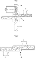
- Figs. 1 and 2 are sequential flow diagrams illustrating a method for connecting members together.
- Each fiber reinforced resin member 3 contains a matrix resin, which is a thermoplastic resin 1, and also contains a fiber material 2, which is adapted to reinforce the member and serves as a heating element that can generate heat from heat provided thereto, in the thermoplastic resin 1.
- the shape of the fiber reinforced resin member 3 may be, in addition to a planar shape shown in the drawing, a variety of shapes and configurations including a three-dimensional shape (i.e., a curved shape, a wavy shape, or a unitary shape of curves and planes).
- thermoplastic resin 1 it is possible to use one of crystalline plastic such as polyethylene (PE), polypropylene (PP), polyamide (PA, for example, Nylon 6 or Nylon 66), polyacetal (POM), or poly(ethyleneterephthalate) (PET); amorphous plastic such as polystyrene (PS), polyvinyl chloride (PVC), poly methyl methacrylate (PMMA), ABS resin, or thermoplastic epoxy; or a material containing a mixture of two or more of them.
- crystalline plastic such as polyethylene (PE), polypropylene (PP), polyamide (PA, for example, Nylon 6 or Nylon 66), polyacetal (POM), or poly(ethyleneterephthalate) (PET); amorphous plastic such as polystyrene (PS), polyvinyl chloride (PVC), poly methyl methacrylate (PMMA), ABS resin, or thermoplastic epoxy; or a material containing a mixture of two or more of them.
- PE polyethylene
- PP polyprop
- the fiber material 2 that serves as a heating element, it is possible to use one of carbon fibers including graphite; metal fibers such as an Ni-Cr alloy, a Fe-Cr-Al alloy, molybdenum, tungsten, or platinum; ceramic fibers such as SiC (silicon carbide) or MoSi 2 (molybdenum disilicide); or a mixture of two or more of them.
- carbon fibers including graphite
- metal fibers such as an Ni-Cr alloy, a Fe-Cr-Al alloy, molybdenum, tungsten, or platinum
- ceramic fibers such as SiC (silicon carbide) or MoSi 2 (molybdenum disilicide); or a mixture of two or more of them.
- the fiber material 2 may be either short fibers or long fibers, or further, continuous fibers.
- a fiber reinforced resin member 3 that contains a 10 to 50 volume % fiber material 2 with respect to the entire volume of the member can be used.
- heat of the fiber material at a position of superposition can be transferred to regions other than the position of superposition.
- short fibers with a length not more than 10 mm, or long fibers with a length not more than 30 mm are desirably used as the fiber material to be used.
- the two fiber reinforced resin members 3,3 are partially superposed one on top of the other so as to form a position of superposition K, and then, the attitudes of the fiber reinforced resin members 3,3 are held with a jig (not shown). Then, a punch P is disposed at the top and bottom positions corresponding to the position of superposition K, and further, an induction coil C arranged in a circuit, which has an AC power supply above the position of superposition K, is disposed.
- connection structure 10 of the members that has high connection strength due to welding is formed as shown in Fig. 2 .
- the material of the fiber material 2 and the material of the thermoplastic resin 1 are selected so that the thermoplastic resin 1 is melted by the heat generation temperature of the fiber material 2 that serves as a heating element.
- thermoplastic resin 1 softens in the entire range of the position of superposition K as long as the fiber material 2 is evenly dispersed in the fiber reinforced resin member 3. Then, the two members are firmly welded together, whereby a connection structure having about the same level of connection strength over the entire range of the position of superposition K can be formed.
- a method using dielectric heating may also be used besides the method using induction heating.
- connection method shown in the drawing it is possible to connect members with the connection structure 10 having about the same high level of connection strength over the entire range of the position of superposition K without being influenced by the shapes of the members at the position of superposition K, without requiring a connecting part.
- connection method is an extremely simple connection method that includes superposing members one on top of the other, and heating the fiber material 2, which is a heating element, at the position of superposition using a method such as induction heating while applying pressure thereto, thereby melting the surrounding thermoplastic resin 1. Therefore, processing efficiency can be significantly improved without requiring a high level of processing skill, and connection of the members can be attained in a short time.
- Figs. 3 to 5 are sequential flow diagrams illustrating the Embodiment of a method for connecting members together of the present invention.
- connection method shown herein is a method that is suitable for a case where the fiber reinforced resin members 3, which are members to be connected together, have relatively large dimensions.
- the fiber reinforced resin members 3, which are members to be connected together have relatively large dimensions
- the fiber reinforced resin members 3,3 often have no mutually-complementary warps or deformations.
- the two materials are attempted to be connected together with such warps or deformations left, it would be impossible to form a position of superposition with high accuracy, and consequently, it becomes impossible to form a connection structure having about the same level of connection strength over the entire range of the position of superposition.
- a self-piercing rivet 4 is driven at the position of superposition K from above as shown in Fig. 3 so that the two members are temporarily joined together. Then, warps or deformations are forcibly modified to form a position of superposition K where the members are tightly attached to each other.
- the self-piercing rivet 4 used herein has a circular end face in a planar view, and exhibits a portal shape in a longitudinal sectional view of a cylindrical body that protrudes from the end face.
- the self-piercing rivet 4 is formed from aluminum, an aluminum alloy, steel, stainless steel, or the like.
- the members at the position of superposition K are put on a rivet dice (not shown), and a punch is caused to slide within a cylinder (not shown), so that the self-piercing rivet 4 is pushed into the members at the position of superposition K with the punch. Accordingly, in the process in which the body of the self-piercing rivet penetrates into the members at the position of superposition K, the self-piercing rivet opens outward through plastic deformation while receiving pressure from the inside thereof, whereby the members at the position of superposition K are temporarily joined together.
- a magnetic field is caused to be generated by allowing current to flow through the induction coil C while applying pressure Q at the position of superposition K with punches P,P above and below the position of superposition K, and the fiber material 2 is caused to generate heat with the Joule heat as shown in Fig. 4 , which shows substantially the same method as the afore mentioned connection method.
- the surrounding thermoplastic resin 1 is melted with the heat generated from the fiber material 2, and the members at the position of superposition K are firmly attached to each other with the pressure Q applied thereto, and then, the melted thermoplastic resin 1 hardens.
- a connection structure 10A of the members that has high connection strength due to welding is formed as shown in Fig. 5 .
- test pieces in accordance with Examples 1 and 2 are obtained by welding two sheet materials together through induction heating.
- An electromagnetic induction oscillator (UH 2.5K) of SEIDENSHA ELECTRONICS CO., LTD. was used, and an oscillation coil in spiral form was used.
- a test piece was produced by placing a PBT plate with a predetermined thickness to provide a gap on the oscillation coil, and disposing the sheet materials at a position of superposition on the plate, and further applying pressure thereto from above using a metal bar for 60 seconds, and then releasing the pressure.
- Examples 1 and 2 differ in the gap (i.e., gap from the coil) and the current value as shown in Table 1.
- a test piece was produced by applying a flame treatment to sheet materials at a position of superposition, applying Primer M (RC-50E, product of The Yokohama Rubber Company, Limited) thereto, applying an adhesive Mighty Grip 5000/5030 (a product of Emulsion Technology Co., Ltd., a mixing ratio of 2:1) between the sheet materials, fixing the sheet materials with a clip, and applying a thermal treatment thereto at 60 °C for 90 minutes in an oven to harden the adhesive.
- Primer M RC-50E, product of The Yokohama Rubber Company, Limited
- an adhesive Mighty Grip 5000/5030 a product of Emulsion Technology Co., Ltd., a mixing ratio of 2:1
- a test piece was produced by applying a flame treatment to sheet materials at a position of superposition, applying Primer M (RC-50E, product of The Yokohama Rubber Company, Limited) thereto, applying an adhesive DENATITE 3327SR (a product of Nagase ChemteX Corporation) between the sheet materials, fixing the sheet materials with a clip, and applying a thermal treatment thereto at 60 °C for 90 minutes in an oven to harden the adhesive.
- Primer M RC-50E, product of The Yokohama Rubber Company, Limited
- DENATITE 3327SR a product of Nagase ChemteX Corporation
- Model 5582 of Instron was used, and the maximum load (kN) as well as the tensile shearing strength (MPa) at that time was measured at a tension speed of 5 mm/minute and an inter-chuck distance of 100 mm.
- connection time field indicates the time taken for fixation after welding or adhesion.
- Table 1 can confirm that the tensile shearing strength of Example 1 is higher than that of Comparative Example 1 by about 80 %, and is higher than that of Comparative Example 2 by about 160 %.
- Example 2 The tensile shearing strength of Example 2 is higher than that of Comparative Example 1 by about 130 %, and is higher than that of Comparative Example 2 by about 230 %. Thus, it can be verified that the connection strengths of Examples 1 and 2 are each higher than those of the comparative examples in which adhesives are used.
Description
- The present invention relates to a method for connecting two or more members together at a position of superposition. Further, a connection structure is disclosed. In particular, the present invention relates to a method for connecting members together, at least one of the members for forming the position of superposition being a fiber reinforced resin member containing a matrix resin and also containing a reinforcing fiber material in the matrix resin. Further, a connection structure of members formed by such a method is disclosed.
- A fiber reinforced resin member (i.e., fiber reinforced plastic (FRP)) that contains a resin and also contains a reinforcing fiber material in the resin is used in various industrial fields, such as an automobile industry, construction industry, and airline industry, by virtue of its lightweight and high strength.
- For connection of fiber reinforced resin members together, a connection method using an adhesive, a connection method using a bolt, a combination of such connection methods, or the like is commonly used.
- Meanwhile, for connection of metal members, such as an aluminum plate and a steel plate, together, a connection method using spot welding, friction-stir welding, mechanical clinching, brazing, screwing, self-piercing riveting, or the like is commonly used.
- Further, for connection of a fiber reinforced resin member and a metal member together, that is, for connection of dissimilar members together, connection is carried out using one of the aforementioned methods, or two or more of them in combination.
- The aforementioned connection methods that have been used so far for connection of so-called similar members together, such as connection of fiber reinforced resin members together or connection of metal members together, or for connection of so-called dissimilar members together, such as connection of a fiber reinforced resin member and a metal member together, have various problems. Specifically, there are problems in that when an adhesive is used, it takes a long time for adhesion, and when a bolt, screwing, self-piercing riveting, or the like is used, a connecting part is necessary; thus, the production time would increase or the production cost associated with the connecting part would increase.
- In particular, when members with three-dimensionally complicated shapes are connected together using a connecting part such as a bolt, it would be not easy to handle alignment between the members to be connected together, and thus, complicated assembly procedures would be needed to connect the members together using the connecting part. Meanwhile, when a connection method using adhesion or welding is used, it is easily understood that it is quite difficult to uniformly apply an adhesive to or uniformly apply heat to all of the portions to be connected that are three-dimensionally complicated (at a position of superposition) as soon as possible.
- Herein,
Patent Literature 1 discloses a method for connecting members together using non-contact heat plate welding after applying an antioxidant to a joint portion. - According to such a connection method, it may be possible to form a joint portion with small variations in strength. However, since heating is conducted in the air, heat transfer efficiency is low and it thus takes a long time to join the members together through heating. Thus, the aforementioned problem cannot be solved. Further, even when such a connection method is used, it is still quite difficult to uniformly apply heat to all of the portions to be connected that have three-dimensionally complicated shapes (at a position of superposition) as soon as possible.
- Thus, in order to connect two or more members together at a position of superposition, for example, to connect members having three-dimensionally complicated portions to be connected together, there has been sought an invention of a method for connecting members together that can easily form a connection structure having about the same high level of connection strength over the entire range of the position of superposition.
- Moreover,
Patent Literature 2 relates to the bonding of thermoplastic layers and discloses a method of bonding a thermoplastic layer, such as APC-2, to a substrate in which the thermoplastic layer comprises electrical conductors such as carbon fibers, embedded in thermoplastic material such as PEEK. -
Patent Literature 3 relates to the joining of composite materials by induction heating and discloses that two pieces of composite material are simultaneously joined together throughout an interface between the two pieces, by induction heating the interface region with an induction coil placed, at least in part, adjacent to the bonding region, and forcing the composite material at the interface together while heating. -
Patent Literature 4 relates to a thermoplastic composite induction welder and discloses that an induction heating of thermoplastic composite materials is accomplished to form a continuous bonded joint. - Patent Literature 5 relates to an FRP joint structure and the provision of an FRP joint structure which develops excellent joining strength, has excellent productivity and can prevent the damage of an FRP member in the joint part.
-
Non-Patent Literature 1 relates to induction heated joining of thermoplastic composites without metal susceptors and describes experiments relating to the same. -
- Patent Literature 1:
JP 2010-228798 A - Patent Literature 2:
EP 0 281 347 A2 - Patent Literature 3:
US 5 240 542 A - Patent Literature 4:
US 4 978 825 A - Patent Literature 5:
JP 2007 229980 A - Non-Patent Literature 1: BORDER ET AL: "Induction Heated Joining of Thermoplastic Composites Without Metal Susceptors", 34TH INTERNATIONAL SAMPLE SYMPOSIUM, MAY 8-11, 1989, 8 May 1989 (1989-05-08), pages 2569-2578, XP009180883
- The present invention has been made in view of the foregoing problems, and it is an object of the present invention to provide a method for connecting members together that can easily form a connection structure, which has about the same high level of connection strength over the entire range of the position of superposition, in a short time. Further, a connection structure is disclosed.
- In order to achieve the aforementioned object, the method for connecting members together in accordance with the present invention is a method for connecting members together, the method being adapted to connect two or more members together, at least one of which is a fiber reinforced resin member containing a thermoplastic resin and also containing a reinforcing fiber material that serves as a heating element in the thermoplastic resin, at a position of superposition. The method includes pressing the members against each other while heating the members at a position of superposition using one of induction heating or dielectric heating and thus melting the thermoplastic resin with heat generated from the fiber material that serves as the heating element, thereby connecting the members together.
- The method for connecting members together of the present invention is a method for connecting members, the method being adapted to connect two or more members together, at least one of which is a fiber reinforced resin member containing a thermoplastic resin and also containing a reinforcing fiber material that serves as a heating element in the thermoplastic resin, at a position of superposition.
- Thus, examples of a combination of the members to be connected together include the following. One example is a configuration in which each of two members is a fiber reinforced resin member, or a configuration in which one of the two members is a fiber reinforced resin member and the other is a resin member not containing a fiber material. Another example is a configuration in which one of the two members is a metal member and the other is a dissimilar member such as a fiber reinforced resin member, a configuration in which one or two of three or more members is/are a fiber reinforced resin member(s) and the other(s) is/are resin member(s) not containing a fiber material or a metal member(s), or a configuration in which all of three or more members are fiber reinforced resin members. It should be noted that when three members to be connected are connected together and only one of them is a fiber reinforced resin member, the fiber reinforced resin member is arranged in the middle of the three members.
- Examples of the fiber reinforced resin member include a member containing a thermoplastic resin and also containing long fibers or short fibers in random order in the thermoplastic resin, for example, a unidirectional material (UD material) in which continuous fibers of over 50 mm are unidirectionally oriented in a thermoplastic resin as defined by JIS, or a quasi-isotropic material (e.g., a multi-axial laminate or a woven fabric made of warps and wefts). Examples of its application include a frame structure member of a vehicle, such as a front side member, a center cross member, a pillar, a locker, or a floor of the body, and a non-structural member, such as a door outer panel or a hood that requires a unique design. When a fiber reinforced resin member is applied to a frame structure member of a vehicle or the like, it is possible to produce a fuel-efficient, environmentally-friendly vehicle while ensuring strength and lightweight.
- Examples of a thermoplastic resin for forming a fiber reinforced resin member include crystalline plastic such as polyamide (PA) and polypropylene (PP) and amorphous plastic such as polystyrene (PS) and polyvinyl chloride (PVC).
- One of the features of the connection method of the present invention is that a thermoplastic resin of a fiber reinforced resin member, which is a member to be connected, contains a fiber material for reinforcement that can serve as a heating element.
- The fiber material that serves as a heating element is heated using one of induction heating or dielectric heating, whereby the heating element is caused to generate heat, and the surrounding thermoplastic resin is melted with the heat. Accordingly, when the fiber material is evenly dispersed in the thermoplastic resin, it is possible to evenly melt the fiber reinforced resin member in the entire range of the position of superposition.
- Before or after the thermoplastic resin is melted, pressure is continuously applied to the members at the position of superposition for a predetermined period of time to harden the interface of the melted fiber reinforced resin member, whereby the members can be connected together.
- When such a connection method is used, the heating element, which is contained in the fiber reinforced resin member in advance, is caused to generate heat, and the thermoplastic resin is melted with the heat. Thus, a separate connecting part is not necessary at all.
- Since heating is conducted using one of induction heating or dielectric heating, each of such heating methods allows a relatively wide range of area to be heated to about the same degree, and thus allows the fiber material, which serves as a heating element, in the entire range of the portion of superposition to be heated to about the same degree without being influenced by the shapes of the members at the position of superposition. Thus, even when the members at the position of superposition exhibit three-dimensionally complicated shapes, connection can occur with about the same high level of connection strength over the entire range of the position of superposition.
- The term "induction heating" herein is a method of arranging the position of superposition of members within or around a coil that is connected to an AC power supply and flowing current through the coil, thereby causing high-density current (eddy current) to be generated in the heating element through electromagnetic induction, and thus causing the heating element to generate heat with the Joule heat.
- Meanwhile, the term "dielectric heating" is a method of arranging the position of superposition of members within an AC electric field with a high frequency of several MHz to several hundred MHz, thereby causing the heating element to generate heat through the action of the high frequency (electromagnetic waves). It should be noted that heating conducted with electromagnetic waves with a frequency of 1 MHz to 200 MHz is referred to as high-frequency dielectric heating, and heating conducted with electromagnetic waves with a lower frequency band that that is referred to as microwave heating.
- In addition to induction heating and dielectric heating, a heating method such as ultrasonic welding or hot plate vibration heating may also be used. Such methods are adapted to generate frictional heat by providing vibration to the connection planes of the members to be connected together, thereby connecting the members to be connected together with the frictional heat. Therefore, a large frictional force or pressure acts around the interface between the members to be connected together, which is disadvantageous in that blurs are likely to be generated. In contrast, when induction heating or dielectric heating is used, heat is allowed to be generated from the inside of the members to be connected together. Therefore, the time needed for melting can be short. Further, since connection can be carried out with less pressure, a problem that many blurs may be generated at the interface cannot occur.
- For the fiber material that serves as a "heating element," one of carbon fibers, metal fibers, or ceramic fibers, or a mixture of two or more of them can be used.
- Herein, examples of carbon fibers include graphite. Examples of metal fibers include a Ni-Cr alloy, a Fe-Cr-Al alloy, molybdenum, tungsten, and platinum. Examples of ceramic fibers include SiC (silicon carbide) and MoSi2 (molybdenum disilicide).
- The aforementioned method for connecting members together of the present invention employs a novel and simple connection method that includes pressing a plurality of members to be connected together, at least one of which is a fiber reinforced resin member containing a thermoplastic resin and also containing a fiber material that serves as a heating element in the thermoplastic resin, against each other at a position of superposition while heating the members using one of induction heating or dielectric heating. Accordingly, the members can be connected together with a connection structure having about the same high level of connection strength over the entire range of the position of superposition without being influenced by the shapes of the members at the position of superposition. It should be noted that although a connection part is not necessary, the connection method of the present invention may also be combined with the use of an adhesive, a bolt, or the like as needed, so that a connection structure can be formed through a combination of such methods as appropriate.
- Further, according to the embodiment of a method for connecting members together of the present invention, two or more members are temporarily joined together at a position of superposition using a self-piercing rivet before heating is applied to the members at the position of superposition. Then, the thermoplastic resin is melted through heating, and pressure is applied thereto.
- When the members to be connected together have large dimensions, it becomes possible to eliminate the need to use a large jig for holding the whole members by modifying warps and deformations of the members to be connected together before connecting them. Thus, it is possible to facilitate the connection processing and produce a connection structure having a high level of connection strength over the entire range of the position of superposition.
- In addition, when a self-piercing rivet is used for the temporary joint, the self-piercing rivet also serves as a heating element. Thus, melting of the thermoplastic resin can be promoted, which leads to a further reduction in the production time.
- Further, a connection structure of members is disclosed, and such connection structure is a connection structure of two or more members, at least one of which is a fiber reinforced resin member containing a thermoplastic resin and also containing a reinforcing fiber material that serves as a heating element in the thermoplastic resin, connected together at a position of superposition. The connection structure is formed by pressing the members against each other while heating the members at the position of superposition using one of induction heating or dielectric heating and thus melting the thermoplastic resin with heat generated from the fiber material that serves as the heating element.
- In the connection structure, the members are directly connected together without other members or additives for connecting the members interposed between the members at the position of superposition.
- As can be understood from the foregoing description, according to the method for connecting members together of the present invention, a plurality of members to be connected together, at least one of which is a fiber reinforced resin member containing a thermoplastic resin and also containing a fiber material that serves as a heating element in the thermoplastic resin, are pressed against each other at a position of superposition while heat is applied thereto using one of induction heating or dielectric heating, whereby a connection structure having about the same high level of connection strength over the entire range of the connection portion can be easily formed in a short time.
-
- [
Fig. 1] Fig. 1 is a diagram illustratinga method for connecting members together. - [
Fig. 2] Fig. 2 is a schematic diagram showing a connection structure formed in the connection method. - [
Fig. 3] Fig. 3 is a diagram illustrating an Embodiment of a method for connecting members together. - [
Fig. 4] Fig. 4 is a diagram illustrating the Embodiment of the connection method, followingFig. 3 . - [
Fig. 5] Fig. 5 is a schematic diagram illustrating a connection structure formed in the Embodiment of the connection method. - Hereinafter, the embodiment of a method for connecting members together of the present invention will be described with reference to the drawings. Although the examples shown in the drawings illustrate methods for connecting two fiber reinforced resin members together, it is needless to mention that three or more members to be connected may also be connected together using the methods shown in the drawings. Further, it is also needless to mention that a configuration for connecting a fiber reinforced resin member and a resin member not containing a fiber material, and a configuration for connecting a fiber reinforced resin member and a metal member may also be used.
-
Figs. 1 and 2 are sequential flow diagrams illustrating a method for connecting members together. - First, two fiber reinforced
resin members 3, which are members to be connected together, are prepared. Each fiber reinforcedresin member 3 contains a matrix resin, which is athermoplastic resin 1, and also contains afiber material 2, which is adapted to reinforce the member and serves as a heating element that can generate heat from heat provided thereto, in thethermoplastic resin 1. - It should be noted that the shape of the fiber reinforced
resin member 3 may be, in addition to a planar shape shown in the drawing, a variety of shapes and configurations including a three-dimensional shape (i.e., a curved shape, a wavy shape, or a unitary shape of curves and planes). - Herein, for the
thermoplastic resin 1, it is possible to use one of crystalline plastic such as polyethylene (PE), polypropylene (PP), polyamide (PA, for example, Nylon 6 or Nylon 66), polyacetal (POM), or poly(ethyleneterephthalate) (PET); amorphous plastic such as polystyrene (PS), polyvinyl chloride (PVC), poly methyl methacrylate (PMMA), ABS resin, or thermoplastic epoxy; or a material containing a mixture of two or more of them. - For the
fiber material 2 that serves as a heating element, it is possible to use one of carbon fibers including graphite; metal fibers such as an Ni-Cr alloy, a Fe-Cr-Al alloy, molybdenum, tungsten, or platinum; ceramic fibers such as SiC (silicon carbide) or MoSi2 (molybdenum disilicide); or a mixture of two or more of them. - The
fiber material 2 may be either short fibers or long fibers, or further, continuous fibers. For example, a fiber reinforcedresin member 3 that contains a 10 to 50 volume% fiber material 2 with respect to the entire volume of the member can be used. Needless to say, when continuous fibers are used, heat of the fiber material at a position of superposition can be transferred to regions other than the position of superposition. Thus, short fibers with a length not more than 10 mm, or long fibers with a length not more than 30 mm are desirably used as the fiber material to be used. - The two fiber reinforced
resin members resin members - Next, current is allowed to flow through the induction coil C while pressure Q is applied at the position of superposition K with the punches P,P above and below the position of superposition K, whereby high-density current (eddy current) is generated in the
fiber material 2, which serves as a heating element, through electromagnetic induction, and the resulting Joule heat causes thefiber material 2 to generate heat (i.e., a method using induction heating). - With the heat generated from the
fiber material 2, the surroundingthermoplastic resin 1 is melted, and the members at the position of superposition K firmly adhere to each other with the pressure Q applied thereto, and then, the meltedthermoplastic resin 1 hardens and the two members are welded together. Thus, aconnection structure 10 of the members that has high connection strength due to welding is formed as shown inFig. 2 . - As described above, the material of the
fiber material 2 and the material of thethermoplastic resin 1 are selected so that thethermoplastic resin 1 is melted by the heat generation temperature of thefiber material 2 that serves as a heating element. - When the entire length of the position of superposition K is long, it is possible to construct a production system that allows the induction coil C to freely move above the position of superposition K, and employ a method of melting the
thermoplastic resin 1 in the entire range of the position of superposition K while sequentially running the induction coil C. - Even when the entire length of the position of superposition K is long or the member at the position of superposition K (and the entire fiber reinforced resin member 3) exhibits a three-dimensionally complicated shape, the
thermoplastic resin 1 softens in the entire range of the position of superposition K as long as thefiber material 2 is evenly dispersed in the fiber reinforcedresin member 3. Then, the two members are firmly welded together, whereby a connection structure having about the same level of connection strength over the entire range of the position of superposition K can be formed. - It should be noted that a method using dielectric heating may also be used besides the method using induction heating.
- According to the connection method shown in the drawing, it is possible to connect members with the
connection structure 10 having about the same high level of connection strength over the entire range of the position of superposition K without being influenced by the shapes of the members at the position of superposition K, without requiring a connecting part. - In addition, such a connection method is an extremely simple connection method that includes superposing members one on top of the other, and heating the
fiber material 2, which is a heating element, at the position of superposition using a method such as induction heating while applying pressure thereto, thereby melting the surroundingthermoplastic resin 1. Therefore, processing efficiency can be significantly improved without requiring a high level of processing skill, and connection of the members can be attained in a short time. -
Figs. 3 to 5 are sequential flow diagrams illustrating the Embodiment of a method for connecting members together of the present invention. - The connection method shown herein is a method that is suitable for a case where the fiber reinforced
resin members 3, which are members to be connected together, have relatively large dimensions. - When the fiber reinforced
resin members 3, which are members to be connected together, have relatively large dimensions, the fiber reinforcedresin members - Thus, first, a self-piercing
rivet 4 is driven at the position of superposition K from above as shown inFig. 3 so that the two members are temporarily joined together. Then, warps or deformations are forcibly modified to form a position of superposition K where the members are tightly attached to each other. - The self-piercing
rivet 4 used herein has a circular end face in a planar view, and exhibits a portal shape in a longitudinal sectional view of a cylindrical body that protrudes from the end face. The self-piercingrivet 4 is formed from aluminum, an aluminum alloy, steel, stainless steel, or the like. - The members at the position of superposition K are put on a rivet dice (not shown), and a punch is caused to slide within a cylinder (not shown), so that the self-piercing
rivet 4 is pushed into the members at the position of superposition K with the punch. Accordingly, in the process in which the body of the self-piercing rivet penetrates into the members at the position of superposition K, the self-piercing rivet opens outward through plastic deformation while receiving pressure from the inside thereof, whereby the members at the position of superposition K are temporarily joined together. - When the self-piercing
rivet 4 is used for the temporary joint as described above, the self-piercingrivet 4 made of metal also serves as a heating element. Thus, melting of thethermoplastic resin 1 is further promoted, and a further reduction in the production time can be achieved. - Though not shown, spot joining through ultrasonic spot welding may also be used as the method for temporarily joining the members together at the position of superposition K, besides the self-piercing riveting. According to such a method, it is possible to form the position of superposition K where the members are tightly attached to each other by forcibly modifying warps or deformations of the members without using another member, as in self-piercing riveting.
- After the members are temporarily joined together at the position of superposition K with the self-piercing
rivet 4, a magnetic field is caused to be generated by allowing current to flow through the induction coil C while applying pressure Q at the position of superposition K with punches P,P above and below the position of superposition K, and thefiber material 2 is caused to generate heat with the Joule heat as shown inFig. 4 , which shows substantially the same method as the afore mentioned connection method. Then, the surroundingthermoplastic resin 1 is melted with the heat generated from thefiber material 2, and the members at the position of superposition K are firmly attached to each other with the pressure Q applied thereto, and then, the meltedthermoplastic resin 1 hardens. Thus, aconnection structure 10A of the members that has high connection strength due to welding is formed as shown inFig. 5 . - The inventors created a variety of test pieces in accordance with the following examples and comparative examples by using two sheet materials of TEIJIN LIMITED (with a long side of 100 mm × a short side of 25 mm × a thickness of 2 mm in planar dimensions) each containing a matrix resin as a thermoplastic resin (PA6) and also containing carbon fibers (a carbon fiber content of Vf 30) in the thermoplastic resin, and superposing the two sheet materials one on top of the other, with a long side in the range of 10 mm as a region of superposition. Table 1 shows the detailed conditions and experimental result of each example and comparative example.
- Each of test pieces in accordance with Examples 1 and 2 is obtained by welding two sheet materials together through induction heating. An electromagnetic induction oscillator (UH 2.5K) of SEIDENSHA ELECTRONICS CO., LTD. was used, and an oscillation coil in spiral form was used.
- A test piece was produced by placing a PBT plate with a predetermined thickness to provide a gap on the oscillation coil, and disposing the sheet materials at a position of superposition on the plate, and further applying pressure thereto from above using a metal bar for 60 seconds, and then releasing the pressure. Examples 1 and 2 differ in the gap (i.e., gap from the coil) and the current value as shown in Table 1.
- A test piece was produced by applying a flame treatment to sheet materials at a position of superposition, applying Primer M (RC-50E, product of The Yokohama Rubber Company, Limited) thereto, applying an adhesive Mighty Grip 5000/5030 (a product of Emulsion Technology Co., Ltd., a mixing ratio of 2:1) between the sheet materials, fixing the sheet materials with a clip, and applying a thermal treatment thereto at 60 °C for 90 minutes in an oven to harden the adhesive.
- The "flame treatment" herein is a treatment for destroying molecular bonds on the surface of plastic with the heat of flame plasma irradiation, and then embedding part of oxygen in the flame into the molecular bonds.
- A test piece was produced by applying a flame treatment to sheet materials at a position of superposition, applying Primer M (RC-50E, product of The Yokohama Rubber Company, Limited) thereto, applying an adhesive DENATITE 3327SR (a product of Nagase ChemteX Corporation) between the sheet materials, fixing the sheet materials with a clip, and applying a thermal treatment thereto at 60 °C for 90 minutes in an oven to harden the adhesive.
- As a testing device, Model 5582 of Instron was used, and the maximum load (kN) as well as the tensile shearing strength (MPa) at that time was measured at a tension speed of 5 mm/minute and an inter-chuck distance of 100 mm.
[Table 1] Unit Example 1 Example 2 Comparative Example 1 Comparative Example 2 Connection Method Induction Heating Induction Heating Adhesive Mighty Grip Adhesive DENATITE Connection Time Seconds Oscillation: 10 Holding: 50 Oscillation: 10 Holding: 50 Application: Several Minutes Hardening: 540 Application: Several Minutes Hardening: 540 Gap mm 8 6 - - Pressure Applied kN 0.3 0.3 Not Measured Not Measured Current Value mA 1080 865 - - Amplitude µm - - - - Maximum Load kN 7.45 9.57 4.19 2.88 Tensile Shearing Strength MPa 29.8 38.3 16.8 11.5 - In Table 1, the term "Holding" in the connection time field indicates the time taken for fixation after welding or adhesion.
- Regarding the pressure applied of Comparative Examples 1 and 2, an adhesive was applied to a thickness of 0.3 mm, and a spacer of φ 0.15 mm was interposed, and then the members were bonded together with a pressure applied to the thickness.
- Table 1 can confirm that the tensile shearing strength of Example 1 is higher than that of Comparative Example 1 by about 80 %, and is higher than that of Comparative Example 2 by about 160 %.
- The tensile shearing strength of Example 2 is higher than that of Comparative Example 1 by about 130 %, and is higher than that of Comparative Example 2 by about 230 %. Thus, it can be verified that the connection strengths of Examples 1 and 2 are each higher than those of the comparative examples in which adhesives are used.
-
- 1
- Thermoplastic resin
- 2
- Fiber material (heating element)
- 3
- Fiber reinforced resin member (Member to be connected)
- 4
- Self-piercing rivet
- 10, 10A
- Connection structure
- C
- Induction coil
- P
- Punch
- K
- Position of superposition
- Q
- Pressure
Claims (2)
- A method for connecting members together, the method being adapted to connect two or more members together at a position of superposition, at least one of the two or more members being a fiber reinforced resin member (3) containing a thermoplastic resin (1) and also containing a reinforcing fiber material (2) that serves as a heating element in the thermoplastic resin (1), the method comprising:temporarily joining the two or more members together at the position of superposition using a self-piercing rivet (4) before heating the members at the position of superposition; andpressing the members against each other while heating the members at the position of superposition using one of induction heating or dielectric heating and thus melting the thermoplastic resin (1) with heat generated from the fiber material (2) that serves as the heating element, thereby connecting the members together.
- The method for connecting members together according to claim 1, wherein the fiber material (2) contains one of carbon fibers, metal fibers, or ceramic fibers, or a mixture of two or more of the fibers.
Applications Claiming Priority (1)
| Application Number | Priority Date | Filing Date | Title |
|---|---|---|---|
| PCT/JP2011/079431 WO2013094008A1 (en) | 2011-12-20 | 2011-12-20 | Method for connecting members and connection structure |
Publications (3)
| Publication Number | Publication Date |
|---|---|
| EP2796272A1 EP2796272A1 (en) | 2014-10-29 |
| EP2796272A4 EP2796272A4 (en) | 2014-12-03 |
| EP2796272B1 true EP2796272B1 (en) | 2017-02-08 |
Family
ID=48667938
Family Applications (1)
| Application Number | Title | Priority Date | Filing Date |
|---|---|---|---|
| EP11878079.0A Not-in-force EP2796272B1 (en) | 2011-12-20 | 2011-12-20 | Method for connecting members |
Country Status (5)
| Country | Link |
|---|---|
| US (1) | US20140356053A1 (en) |
| EP (1) | EP2796272B1 (en) |
| JP (1) | JP5447664B2 (en) |
| CN (1) | CN103987510B (en) |
| WO (1) | WO2013094008A1 (en) |
Families Citing this family (25)
| Publication number | Priority date | Publication date | Assignee | Title |
|---|---|---|---|---|
| US9403328B1 (en) * | 2013-02-08 | 2016-08-02 | The Boeing Company | Magnetic compaction blanket for composite structure curing |
| CN103862671A (en) * | 2014-02-22 | 2014-06-18 | 李文忠 | Hot melt adhesive technology for plastic film engineering construction |
| JP6280839B2 (en) * | 2014-08-22 | 2018-02-14 | 本田技研工業株式会社 | Manufacturing method of fiber reinforced resin joined body |
| CN106715091B (en) * | 2014-10-27 | 2019-01-01 | 三菱电机株式会社 | In conjunction with the manufacturing method of the stator of method, combination, the stator of rotating electric machine and rotating electric machine |
| US11198255B2 (en) * | 2015-05-20 | 2021-12-14 | Magna Exteriors Inc. | Hyrbid welding of thermoplastics |
| WO2017005722A1 (en) * | 2015-07-09 | 2017-01-12 | Woodwelding Ag | Bonding objects together |
| EP3328617B1 (en) * | 2015-07-29 | 2020-06-10 | WoodWelding AG | Method for joining a device to an object with the aid of ultrasonic vibration energy and installation suitable for the method |
| US10464282B2 (en) * | 2016-01-21 | 2019-11-05 | GM Global Technology Operations LLC | Systems and processes for joining workpieces robustly using moguls and adhesive |
| MX2018014173A (en) * | 2016-05-17 | 2019-03-14 | Basf Se | Method for welding molded bodies. |
| JP2018069455A (en) * | 2016-10-24 | 2018-05-10 | 三菱自動車工業株式会社 | Joining method of members |
| FR3063672B1 (en) | 2017-03-13 | 2022-07-01 | Arkema France | METHOD FOR MANUFACTURING PARTS IN THERMOPLASTIC POLYMER COMPOSITE, AND OBJECT OBTAINED BY THE SAID METHOD |
| WO2019012717A1 (en) * | 2017-07-10 | 2019-01-17 | 第一電通株式会社 | Fastening method and fastening device |
| US11260480B2 (en) | 2017-07-10 | 2022-03-01 | Dai-Ichi Dentsu Ltd. | Fastening apparatus and fastener pass/fail determining method |
| JP7051414B2 (en) * | 2017-12-14 | 2022-04-11 | 三菱重工業株式会社 | Composite material molding method and composite material |
| CN108162420B (en) * | 2017-12-26 | 2023-10-10 | 吉林大学 | Self-piercing riveting device and method for thermoplastic carbon fiber composite material plate and alloy plate |
| US10981369B2 (en) | 2018-04-17 | 2021-04-20 | Woodwelding Ag | Method and installation for joining a cover layer to an object, as well as cover layer suitable for the method |
| EP3823818B1 (en) * | 2018-07-16 | 2022-09-07 | Arkema France | Method for welding parts made of thermoplastic material |
| CN109383036B (en) * | 2018-12-10 | 2020-12-04 | 哈尔滨工业大学(威海) | Induction welding equipment and method for thermoplastic resin-based composite material with built-in electromagnetic material |
| US11141927B2 (en) * | 2019-07-01 | 2021-10-12 | The Boeing Company | Hybrid braided composite parts |
| US11235537B2 (en) | 2019-07-01 | 2022-02-01 | The Boeing Company | Hybrid braided composite parts |
| US11040507B2 (en) * | 2019-11-06 | 2021-06-22 | The Boeing Company | Assembly and method to repair thermoplastic composites |
| GB201916362D0 (en) * | 2019-11-11 | 2019-12-25 | Ge Oil & Gas Uk Ltd | Splicing method and apparatus |
| NL2027112B1 (en) * | 2020-12-15 | 2022-07-08 | Kok & Van Engelen Composite Structures B V | Method and device for electromagnetic spot welding of moulded parts |
| NL2027111B1 (en) * | 2020-12-15 | 2022-07-08 | Kok & Van Engelen Composite Structures B V | Method and device for electromagnetic spot welding of moulded parts |
| JP2022154727A (en) * | 2021-03-30 | 2022-10-13 | 川崎重工業株式会社 | Joining method, joined body, and joining device |
Citations (1)
| Publication number | Priority date | Publication date | Assignee | Title |
|---|---|---|---|---|
| JP2007229980A (en) * | 2006-02-28 | 2007-09-13 | Honda Motor Co Ltd | Frp joint structure |
Family Cites Families (19)
| Publication number | Priority date | Publication date | Assignee | Title |
|---|---|---|---|---|
| JPS59133015A (en) * | 1983-01-19 | 1984-07-31 | Shinko:Kk | Preparation of container and equipment cradle made of thermoplastic material reinforced by glass and metal fibers for use in physical distribution |
| JPS59152161A (en) * | 1983-02-15 | 1984-08-30 | 東洋製罐株式会社 | Easy open heat seal cover |
| JPS6157329A (en) * | 1984-08-29 | 1986-03-24 | Nippon Radiator Co Ltd | Part for connecting parts made of synthetic resin with each other and manufacture thereof |
| GB8704852D0 (en) * | 1987-03-02 | 1987-04-08 | Welding Inst | Bonding thermoplastic layers |
| US5025128A (en) * | 1988-12-02 | 1991-06-18 | Metcal, Inc. | Rivet with integral heater |
| US4978825A (en) * | 1989-11-08 | 1990-12-18 | Northrop Corporation | Thermoplastic composite induction welder |
| JP2760874B2 (en) * | 1990-02-28 | 1998-06-04 | 富士重工業株式会社 | Fiber reinforced composite material joining method |
| US5240542A (en) * | 1990-09-06 | 1993-08-31 | The Board Of Trustees Of The Leland Stanford Junior University | Joining of composite materials by induction heating |
| US5248864A (en) * | 1991-07-30 | 1993-09-28 | E. I. Du Pont De Nemours And Company | Method for induction heating of composite materials |
| JPH1047580A (en) * | 1996-08-02 | 1998-02-20 | Fujipura Seiko Co Ltd | Ih resin heater |
| US7341176B2 (en) * | 2002-11-26 | 2008-03-11 | Volvo Aero Corporation | Method of tying two or more components together |
| US7249943B2 (en) * | 2003-08-01 | 2007-07-31 | Alliant Techsystems Inc. | Apparatus for forming composite stiffeners and reinforcing structures |
| GB0609580D0 (en) * | 2006-05-13 | 2006-06-21 | Henrob Ltd | Self-piercing riveting |
| DE102007003357A1 (en) * | 2007-01-17 | 2008-07-24 | Airbus Deutschland Gmbh | Method for bonding a thermoplastic material to a fiber composite material |
| JP4289426B2 (en) * | 2007-09-24 | 2009-07-01 | トヨタ自動車株式会社 | Manufacturing method of fused body |
| JP4937215B2 (en) * | 2008-09-01 | 2012-05-23 | 三菱電機株式会社 | Connection method for thermoplastic resin elongate body |
| AU2009291565B2 (en) * | 2008-09-13 | 2013-11-07 | Philis A. Harvie | Hair accessory and method of styling hair |
| US8087149B2 (en) * | 2008-10-09 | 2012-01-03 | GM Global Technology Operations LLC | Self-piercing rivet and method of joining with bonded riveted joints |
| JP2010228798A (en) | 2009-03-27 | 2010-10-14 | Nichias Corp | Heat insulating container, method for manufacturing heat insulating container, method for bonding molded article made of resin with high melting point, and molded article made of resin with high melting point |
-
2011
- 2011-12-20 US US14/364,515 patent/US20140356053A1/en not_active Abandoned
- 2011-12-20 WO PCT/JP2011/079431 patent/WO2013094008A1/en active Application Filing
- 2011-12-20 CN CN201180075426.8A patent/CN103987510B/en not_active Expired - Fee Related
- 2011-12-20 EP EP11878079.0A patent/EP2796272B1/en not_active Not-in-force
- 2011-12-20 JP JP2012519819A patent/JP5447664B2/en not_active Expired - Fee Related
Patent Citations (1)
| Publication number | Priority date | Publication date | Assignee | Title |
|---|---|---|---|---|
| JP2007229980A (en) * | 2006-02-28 | 2007-09-13 | Honda Motor Co Ltd | Frp joint structure |
Also Published As
| Publication number | Publication date |
|---|---|
| EP2796272A4 (en) | 2014-12-03 |
| CN103987510A (en) | 2014-08-13 |
| WO2013094008A1 (en) | 2013-06-27 |
| JPWO2013094008A1 (en) | 2015-04-27 |
| EP2796272A1 (en) | 2014-10-29 |
| JP5447664B2 (en) | 2014-03-19 |
| CN103987510B (en) | 2015-11-25 |
| US20140356053A1 (en) | 2014-12-04 |
Similar Documents
| Publication | Publication Date | Title |
|---|---|---|
| EP2796272B1 (en) | Method for connecting members | |
| EP2709825B1 (en) | Thermoplastic induction welding apparatus and method | |
| EP2125334B1 (en) | Method of joining a thermoplastic material to a fibre composite material and device manufactured therewith | |
| US5916469A (en) | Susceptor integration into reinforced thermoplastic composites | |
| US5876832A (en) | Precured strips for Z-pin joining of composites | |
| EP0863811B1 (en) | System for inserting elements in composite structure | |
| US10252472B2 (en) | Method for joining fiber-reinforced plastic material | |
| Xiong et al. | Resistance welding technology of fiber reinforced polymer composites: a review | |
| US9925717B2 (en) | Method for connecting a surface-structured workpiece and a plastic workpiece | |
| EP3069851A1 (en) | Resin joined body, manufacturing method of resin joined body, and vehicle structure | |
| JP2013002505A (en) | Connecting method and connecting structure of resin member | |
| US20050184053A1 (en) | Method for bonding thermoplastics | |
| JP5782815B2 (en) | Bonding method and structure of fiber reinforced resin material | |
| WO2017213201A1 (en) | Method for producing bonded body | |
| WO1996040551A1 (en) | Hybrid metal webbed composite beam | |
| JP5811059B2 (en) | Member connection device | |
| KR102300339B1 (en) | Welding method for steel sheet and carbon fiber reinforced plastics sheet | |
| Sickert et al. | Thermal direct joining for hybrid plastic metal structures | |
| JPH03297629A (en) | Manufacture of thermoplastic composite material structure | |
| JP2014213540A (en) | Method for joining fiber-reinforced resin laminate and fiber-reinforced resin molded body | |
| US20220363014A1 (en) | Welding method and structure | |
| Singh et al. | Joining Behaviour of Fibre-Reinforced Polymer Matrix Composites | |
| Dolan et al. | Out-of-autoclave manufacturing of large integrated structures using thermoplastic composite materials | |
| Steiner | Joining: methods and techniques for polypropylene composites | |
| CN106170362A (en) | For using equipment and the process of membrane separator protection ultra-sonic welded angle tool |
Legal Events
| Date | Code | Title | Description |
|---|---|---|---|
| PUAI | Public reference made under article 153(3) epc to a published international application that has entered the european phase |
Free format text: ORIGINAL CODE: 0009012 |
|
| 17P | Request for examination filed |
Effective date: 20140703 |
|
| AK | Designated contracting states |
Kind code of ref document: A1 Designated state(s): AL AT BE BG CH CY CZ DE DK EE ES FI FR GB GR HR HU IE IS IT LI LT LU LV MC MK MT NL NO PL PT RO RS SE SI SK SM TR |
|
| A4 | Supplementary search report drawn up and despatched |
Effective date: 20141104 |
|
| RIC1 | Information provided on ipc code assigned before grant |
Ipc: B29C 65/04 20060101ALI20141029BHEP Ipc: B29C 65/36 20060101AFI20141029BHEP Ipc: B29K 105/06 20060101ALN20141029BHEP |
|
| 17Q | First examination report despatched |
Effective date: 20141120 |
|
| 17Q | First examination report despatched |
Effective date: 20141128 |
|
| DAX | Request for extension of the european patent (deleted) | ||
| RIC1 | Information provided on ipc code assigned before grant |
Ipc: B29C 65/36 20060101AFI20160705BHEP Ipc: B29K 105/06 20060101ALN20160705BHEP Ipc: B29C 65/56 20060101ALI20160705BHEP Ipc: B29C 65/72 20060101ALI20160705BHEP Ipc: B29C 65/04 20060101ALI20160705BHEP |
|
| GRAP | Despatch of communication of intention to grant a patent |
Free format text: ORIGINAL CODE: EPIDOSNIGR1 |
|
| INTG | Intention to grant announced |
Effective date: 20160818 |
|
| GRAS | Grant fee paid |
Free format text: ORIGINAL CODE: EPIDOSNIGR3 |
|
| GRAA | (expected) grant |
Free format text: ORIGINAL CODE: 0009210 |
|
| STAA | Information on the status of an ep patent application or granted ep patent |
Free format text: STATUS: THE PATENT HAS BEEN GRANTED |
|
| AK | Designated contracting states |
Kind code of ref document: B1 Designated state(s): AL AT BE BG CH CY CZ DE DK EE ES FI FR GB GR HR HU IE IS IT LI LT LU LV MC MK MT NL NO PL PT RO RS SE SI SK SM TR |
|
| REG | Reference to a national code |
Ref country code: GB Ref legal event code: FG4D |
|
| REG | Reference to a national code |
Ref country code: CH Ref legal event code: EP Ref country code: AT Ref legal event code: REF Ref document number: 866672 Country of ref document: AT Kind code of ref document: T Effective date: 20170215 |
|
| REG | Reference to a national code |
Ref country code: IE Ref legal event code: FG4D |
|
| REG | Reference to a national code |
Ref country code: DE Ref legal event code: R096 Ref document number: 602011034984 Country of ref document: DE |
|
| REG | Reference to a national code |
Ref country code: LT Ref legal event code: MG4D |
|
| REG | Reference to a national code |
Ref country code: NL Ref legal event code: MP Effective date: 20170208 |
|
| REG | Reference to a national code |
Ref country code: AT Ref legal event code: MK05 Ref document number: 866672 Country of ref document: AT Kind code of ref document: T Effective date: 20170208 |
|
| PG25 | Lapsed in a contracting state [announced via postgrant information from national office to epo] |
Ref country code: LT Free format text: LAPSE BECAUSE OF FAILURE TO SUBMIT A TRANSLATION OF THE DESCRIPTION OR TO PAY THE FEE WITHIN THE PRESCRIBED TIME-LIMIT Effective date: 20170208 Ref country code: FI Free format text: LAPSE BECAUSE OF FAILURE TO SUBMIT A TRANSLATION OF THE DESCRIPTION OR TO PAY THE FEE WITHIN THE PRESCRIBED TIME-LIMIT Effective date: 20170208 Ref country code: NO Free format text: LAPSE BECAUSE OF FAILURE TO SUBMIT A TRANSLATION OF THE DESCRIPTION OR TO PAY THE FEE WITHIN THE PRESCRIBED TIME-LIMIT Effective date: 20170508 Ref country code: GR Free format text: LAPSE BECAUSE OF FAILURE TO SUBMIT A TRANSLATION OF THE DESCRIPTION OR TO PAY THE FEE WITHIN THE PRESCRIBED TIME-LIMIT Effective date: 20170509 Ref country code: HR Free format text: LAPSE BECAUSE OF FAILURE TO SUBMIT A TRANSLATION OF THE DESCRIPTION OR TO PAY THE FEE WITHIN THE PRESCRIBED TIME-LIMIT Effective date: 20170208 |
|
| PG25 | Lapsed in a contracting state [announced via postgrant information from national office to epo] |
Ref country code: RS Free format text: LAPSE BECAUSE OF FAILURE TO SUBMIT A TRANSLATION OF THE DESCRIPTION OR TO PAY THE FEE WITHIN THE PRESCRIBED TIME-LIMIT Effective date: 20170208 Ref country code: SE Free format text: LAPSE BECAUSE OF FAILURE TO SUBMIT A TRANSLATION OF THE DESCRIPTION OR TO PAY THE FEE WITHIN THE PRESCRIBED TIME-LIMIT Effective date: 20170208 Ref country code: PT Free format text: LAPSE BECAUSE OF FAILURE TO SUBMIT A TRANSLATION OF THE DESCRIPTION OR TO PAY THE FEE WITHIN THE PRESCRIBED TIME-LIMIT Effective date: 20170608 Ref country code: BG Free format text: LAPSE BECAUSE OF FAILURE TO SUBMIT A TRANSLATION OF THE DESCRIPTION OR TO PAY THE FEE WITHIN THE PRESCRIBED TIME-LIMIT Effective date: 20170508 Ref country code: LV Free format text: LAPSE BECAUSE OF FAILURE TO SUBMIT A TRANSLATION OF THE DESCRIPTION OR TO PAY THE FEE WITHIN THE PRESCRIBED TIME-LIMIT Effective date: 20170208 Ref country code: AT Free format text: LAPSE BECAUSE OF FAILURE TO SUBMIT A TRANSLATION OF THE DESCRIPTION OR TO PAY THE FEE WITHIN THE PRESCRIBED TIME-LIMIT Effective date: 20170208 Ref country code: ES Free format text: LAPSE BECAUSE OF FAILURE TO SUBMIT A TRANSLATION OF THE DESCRIPTION OR TO PAY THE FEE WITHIN THE PRESCRIBED TIME-LIMIT Effective date: 20170208 Ref country code: NL Free format text: LAPSE BECAUSE OF FAILURE TO SUBMIT A TRANSLATION OF THE DESCRIPTION OR TO PAY THE FEE WITHIN THE PRESCRIBED TIME-LIMIT Effective date: 20170208 |
|
| REG | Reference to a national code |
Ref country code: DE Ref legal event code: R084 Ref document number: 602011034984 Country of ref document: DE |
|
| REG | Reference to a national code |
Ref country code: GB Ref legal event code: 746 Effective date: 20170922 |
|
| PG25 | Lapsed in a contracting state [announced via postgrant information from national office to epo] |
Ref country code: RO Free format text: LAPSE BECAUSE OF FAILURE TO SUBMIT A TRANSLATION OF THE DESCRIPTION OR TO PAY THE FEE WITHIN THE PRESCRIBED TIME-LIMIT Effective date: 20170208 Ref country code: EE Free format text: LAPSE BECAUSE OF FAILURE TO SUBMIT A TRANSLATION OF THE DESCRIPTION OR TO PAY THE FEE WITHIN THE PRESCRIBED TIME-LIMIT Effective date: 20170208 Ref country code: SK Free format text: LAPSE BECAUSE OF FAILURE TO SUBMIT A TRANSLATION OF THE DESCRIPTION OR TO PAY THE FEE WITHIN THE PRESCRIBED TIME-LIMIT Effective date: 20170208 Ref country code: IT Free format text: LAPSE BECAUSE OF FAILURE TO SUBMIT A TRANSLATION OF THE DESCRIPTION OR TO PAY THE FEE WITHIN THE PRESCRIBED TIME-LIMIT Effective date: 20170208 Ref country code: CZ Free format text: LAPSE BECAUSE OF FAILURE TO SUBMIT A TRANSLATION OF THE DESCRIPTION OR TO PAY THE FEE WITHIN THE PRESCRIBED TIME-LIMIT Effective date: 20170208 |
|
| REG | Reference to a national code |
Ref country code: DE Ref legal event code: R097 Ref document number: 602011034984 Country of ref document: DE |
|
| REG | Reference to a national code |
Ref country code: FR Ref legal event code: PLFP Year of fee payment: 7 |
|
| PG25 | Lapsed in a contracting state [announced via postgrant information from national office to epo] |
Ref country code: PL Free format text: LAPSE BECAUSE OF FAILURE TO SUBMIT A TRANSLATION OF THE DESCRIPTION OR TO PAY THE FEE WITHIN THE PRESCRIBED TIME-LIMIT Effective date: 20170208 Ref country code: DK Free format text: LAPSE BECAUSE OF FAILURE TO SUBMIT A TRANSLATION OF THE DESCRIPTION OR TO PAY THE FEE WITHIN THE PRESCRIBED TIME-LIMIT Effective date: 20170208 Ref country code: SM Free format text: LAPSE BECAUSE OF FAILURE TO SUBMIT A TRANSLATION OF THE DESCRIPTION OR TO PAY THE FEE WITHIN THE PRESCRIBED TIME-LIMIT Effective date: 20170208 |
|
| PLBE | No opposition filed within time limit |
Free format text: ORIGINAL CODE: 0009261 |
|
| STAA | Information on the status of an ep patent application or granted ep patent |
Free format text: STATUS: NO OPPOSITION FILED WITHIN TIME LIMIT |
|
| 26N | No opposition filed |
Effective date: 20171109 |
|
| PG25 | Lapsed in a contracting state [announced via postgrant information from national office to epo] |
Ref country code: SI Free format text: LAPSE BECAUSE OF FAILURE TO SUBMIT A TRANSLATION OF THE DESCRIPTION OR TO PAY THE FEE WITHIN THE PRESCRIBED TIME-LIMIT Effective date: 20170208 |
|
| REG | Reference to a national code |
Ref country code: CH Ref legal event code: PL |
|
| REG | Reference to a national code |
Ref country code: IE Ref legal event code: MM4A |
|
| PG25 | Lapsed in a contracting state [announced via postgrant information from national office to epo] |
Ref country code: LU Free format text: LAPSE BECAUSE OF NON-PAYMENT OF DUE FEES Effective date: 20171220 Ref country code: MT Free format text: LAPSE BECAUSE OF NON-PAYMENT OF DUE FEES Effective date: 20171220 |
|
| REG | Reference to a national code |
Ref country code: BE Ref legal event code: MM Effective date: 20171231 |
|
| PG25 | Lapsed in a contracting state [announced via postgrant information from national office to epo] |
Ref country code: IE Free format text: LAPSE BECAUSE OF NON-PAYMENT OF DUE FEES Effective date: 20171220 |
|
| PG25 | Lapsed in a contracting state [announced via postgrant information from national office to epo] |
Ref country code: LI Free format text: LAPSE BECAUSE OF NON-PAYMENT OF DUE FEES Effective date: 20171231 Ref country code: CH Free format text: LAPSE BECAUSE OF NON-PAYMENT OF DUE FEES Effective date: 20171231 Ref country code: BE Free format text: LAPSE BECAUSE OF NON-PAYMENT OF DUE FEES Effective date: 20171231 |
|
| PG25 | Lapsed in a contracting state [announced via postgrant information from national office to epo] |
Ref country code: MC Free format text: LAPSE BECAUSE OF FAILURE TO SUBMIT A TRANSLATION OF THE DESCRIPTION OR TO PAY THE FEE WITHIN THE PRESCRIBED TIME-LIMIT Effective date: 20170208 Ref country code: HU Free format text: LAPSE BECAUSE OF FAILURE TO SUBMIT A TRANSLATION OF THE DESCRIPTION OR TO PAY THE FEE WITHIN THE PRESCRIBED TIME-LIMIT; INVALID AB INITIO Effective date: 20111220 |
|
| PG25 | Lapsed in a contracting state [announced via postgrant information from national office to epo] |
Ref country code: CY Free format text: LAPSE BECAUSE OF FAILURE TO SUBMIT A TRANSLATION OF THE DESCRIPTION OR TO PAY THE FEE WITHIN THE PRESCRIBED TIME-LIMIT Effective date: 20170208 |
|
| PG25 | Lapsed in a contracting state [announced via postgrant information from national office to epo] |
Ref country code: MK Free format text: LAPSE BECAUSE OF FAILURE TO SUBMIT A TRANSLATION OF THE DESCRIPTION OR TO PAY THE FEE WITHIN THE PRESCRIBED TIME-LIMIT Effective date: 20170208 |
|
| PG25 | Lapsed in a contracting state [announced via postgrant information from national office to epo] |
Ref country code: TR Free format text: LAPSE BECAUSE OF FAILURE TO SUBMIT A TRANSLATION OF THE DESCRIPTION OR TO PAY THE FEE WITHIN THE PRESCRIBED TIME-LIMIT Effective date: 20170208 |
|
| PG25 | Lapsed in a contracting state [announced via postgrant information from national office to epo] |
Ref country code: AL Free format text: LAPSE BECAUSE OF FAILURE TO SUBMIT A TRANSLATION OF THE DESCRIPTION OR TO PAY THE FEE WITHIN THE PRESCRIBED TIME-LIMIT Effective date: 20170208 Ref country code: IS Free format text: LAPSE BECAUSE OF FAILURE TO SUBMIT A TRANSLATION OF THE DESCRIPTION OR TO PAY THE FEE WITHIN THE PRESCRIBED TIME-LIMIT Effective date: 20170608 |
|
| PGFP | Annual fee paid to national office [announced via postgrant information from national office to epo] |
Ref country code: DE Payment date: 20211102 Year of fee payment: 11 Ref country code: FR Payment date: 20211115 Year of fee payment: 11 Ref country code: GB Payment date: 20211028 Year of fee payment: 11 |
|
| REG | Reference to a national code |
Ref country code: DE Ref legal event code: R119 Ref document number: 602011034984 Country of ref document: DE |
|
| GBPC | Gb: european patent ceased through non-payment of renewal fee |
Effective date: 20221220 |
|
| PG25 | Lapsed in a contracting state [announced via postgrant information from national office to epo] |
Ref country code: GB Free format text: LAPSE BECAUSE OF NON-PAYMENT OF DUE FEES Effective date: 20221220 Ref country code: DE Free format text: LAPSE BECAUSE OF NON-PAYMENT OF DUE FEES Effective date: 20230701 |
|
| PG25 | Lapsed in a contracting state [announced via postgrant information from national office to epo] |
Ref country code: FR Free format text: LAPSE BECAUSE OF NON-PAYMENT OF DUE FEES Effective date: 20221231 |