US10074043B2 - Image forming apparatus capable of changing operating state - Google Patents
Image forming apparatus capable of changing operating state Download PDFInfo
- Publication number
- US10074043B2 US10074043B2 US13/681,912 US201213681912A US10074043B2 US 10074043 B2 US10074043 B2 US 10074043B2 US 201213681912 A US201213681912 A US 201213681912A US 10074043 B2 US10074043 B2 US 10074043B2
- Authority
- US
- United States
- Prior art keywords
- image forming
- forming apparatus
- human body
- manipulation panel
- detection range
- Prior art date
- Legal status (The legal status is an assumption and is not a legal conclusion. Google has not performed a legal analysis and makes no representation as to the accuracy of the status listed.)
- Active, expires
Links
Images


Classifications
-
- G—PHYSICS
- G06—COMPUTING; CALCULATING OR COUNTING
- G06K—GRAPHICAL DATA READING; PRESENTATION OF DATA; RECORD CARRIERS; HANDLING RECORD CARRIERS
- G06K15/00—Arrangements for producing a permanent visual presentation of the output data, e.g. computer output printers
- G06K15/02—Arrangements for producing a permanent visual presentation of the output data, e.g. computer output printers using printers
-
- G—PHYSICS
- G03—PHOTOGRAPHY; CINEMATOGRAPHY; ANALOGOUS TECHNIQUES USING WAVES OTHER THAN OPTICAL WAVES; ELECTROGRAPHY; HOLOGRAPHY
- G03G—ELECTROGRAPHY; ELECTROPHOTOGRAPHY; MAGNETOGRAPHY
- G03G15/00—Apparatus for electrographic processes using a charge pattern
- G03G15/50—Machine control of apparatus for electrographic processes using a charge pattern, e.g. regulating differents parts of the machine, multimode copiers, microprocessor control
- G03G15/5004—Power supply control, e.g. power-saving mode, automatic power turn-off
-
- G—PHYSICS
- G06—COMPUTING; CALCULATING OR COUNTING
- G06F—ELECTRIC DIGITAL DATA PROCESSING
- G06F1/00—Details not covered by groups G06F3/00 - G06F13/00 and G06F21/00
- G06F1/26—Power supply means, e.g. regulation thereof
- G06F1/32—Means for saving power
- G06F1/3203—Power management, i.e. event-based initiation of a power-saving mode
- G06F1/3206—Monitoring of events, devices or parameters that trigger a change in power modality
- G06F1/3231—Monitoring the presence, absence or movement of users
-
- G—PHYSICS
- G06—COMPUTING; CALCULATING OR COUNTING
- G06F—ELECTRIC DIGITAL DATA PROCESSING
- G06F1/00—Details not covered by groups G06F3/00 - G06F13/00 and G06F21/00
- G06F1/26—Power supply means, e.g. regulation thereof
- G06F1/32—Means for saving power
- G06F1/3203—Power management, i.e. event-based initiation of a power-saving mode
- G06F1/3234—Power saving characterised by the action undertaken
- G06F1/325—Power saving in peripheral device
- G06F1/3284—Power saving in printer
-
- G—PHYSICS
- G06—COMPUTING; CALCULATING OR COUNTING
- G06K—GRAPHICAL DATA READING; PRESENTATION OF DATA; RECORD CARRIERS; HANDLING RECORD CARRIERS
- G06K15/00—Arrangements for producing a permanent visual presentation of the output data, e.g. computer output printers
- G06K15/002—Interacting with the operator
- G06K15/005—Interacting with the operator only locally
-
- G—PHYSICS
- G06—COMPUTING; CALCULATING OR COUNTING
- G06K—GRAPHICAL DATA READING; PRESENTATION OF DATA; RECORD CARRIERS; HANDLING RECORD CARRIERS
- G06K15/00—Arrangements for producing a permanent visual presentation of the output data, e.g. computer output printers
- G06K15/40—Details not directly involved in printing, e.g. machine management, management of the arrangement as a whole or of its constitutive parts
- G06K15/4055—Managing power consumption, e.g. standby mode
- G06K15/406—Wake-up procedures
-
- H—ELECTRICITY
- H04—ELECTRIC COMMUNICATION TECHNIQUE
- H04N—PICTORIAL COMMUNICATION, e.g. TELEVISION
- H04N1/00—Scanning, transmission or reproduction of documents or the like, e.g. facsimile transmission; Details thereof
- H04N1/00127—Connection or combination of a still picture apparatus with another apparatus, e.g. for storage, processing or transmission of still picture signals or of information associated with a still picture
- H04N1/00323—Connection or combination of a still picture apparatus with another apparatus, e.g. for storage, processing or transmission of still picture signals or of information associated with a still picture with a measuring, monitoring or signaling apparatus, e.g. for transmitting measured information to a central location
-
- H—ELECTRICITY
- H04—ELECTRIC COMMUNICATION TECHNIQUE
- H04N—PICTORIAL COMMUNICATION, e.g. TELEVISION
- H04N1/00—Scanning, transmission or reproduction of documents or the like, e.g. facsimile transmission; Details thereof
- H04N1/0035—User-machine interface; Control console
- H04N1/00496—Constructional details of the interface or console not otherwise provided for, e.g. rotating or tilting means
-
- H—ELECTRICITY
- H04—ELECTRIC COMMUNICATION TECHNIQUE
- H04N—PICTORIAL COMMUNICATION, e.g. TELEVISION
- H04N1/00—Scanning, transmission or reproduction of documents or the like, e.g. facsimile transmission; Details thereof
- H04N1/00885—Power supply means, e.g. arrangements for the control of power supply to the apparatus or components thereof
- H04N1/00888—Control thereof
- H04N1/00896—Control thereof using a low-power mode, e.g. standby
-
- H—ELECTRICITY
- H04—ELECTRIC COMMUNICATION TECHNIQUE
- H04N—PICTORIAL COMMUNICATION, e.g. TELEVISION
- H04N1/00—Scanning, transmission or reproduction of documents or the like, e.g. facsimile transmission; Details thereof
- H04N1/00912—Arrangements for controlling a still picture apparatus or components thereof not otherwise provided for
-
- H—ELECTRICITY
- H04—ELECTRIC COMMUNICATION TECHNIQUE
- H04N—PICTORIAL COMMUNICATION, e.g. TELEVISION
- H04N2201/00—Indexing scheme relating to scanning, transmission or reproduction of documents or the like, and to details thereof
- H04N2201/0077—Types of the still picture apparatus
- H04N2201/0094—Multifunctional device, i.e. a device capable of all of reading, reproducing, copying, facsimile transception, file transception
-
- Y—GENERAL TAGGING OF NEW TECHNOLOGICAL DEVELOPMENTS; GENERAL TAGGING OF CROSS-SECTIONAL TECHNOLOGIES SPANNING OVER SEVERAL SECTIONS OF THE IPC; TECHNICAL SUBJECTS COVERED BY FORMER USPC CROSS-REFERENCE ART COLLECTIONS [XRACs] AND DIGESTS
- Y02—TECHNOLOGIES OR APPLICATIONS FOR MITIGATION OR ADAPTATION AGAINST CLIMATE CHANGE
- Y02D—CLIMATE CHANGE MITIGATION TECHNOLOGIES IN INFORMATION AND COMMUNICATION TECHNOLOGIES [ICT], I.E. INFORMATION AND COMMUNICATION TECHNOLOGIES AIMING AT THE REDUCTION OF THEIR OWN ENERGY USE
- Y02D10/00—Energy efficient computing, e.g. low power processors, power management or thermal management
-
- Y02D10/159—
-
- Y02D10/173—
Definitions
- the present invention relates to an image forming apparatus capable of changing an operating state, particularly to an image forming apparatus capable of changing an operating state between a normal mode and a power saving mode having power consumption lower than that of the normal mode.
- Examples of an electrophotographic image forming apparatus in which an image is formed by an electrophotographic system include an MFP (Multi Function Peripheral) having a scanner function, a facsimile function, a copying function, a function as a printer, a data communication function, and a server function, a facsimile machine, a copying machine, and a printer.
- MFP Multi Function Peripheral
- a color (multi-color) image is formed on a recording sheet by the following method.
- a toner image is formed on a surface of an image bearing member by an electrostatic recording method, and the toner image is transferred to an intermediate transfer member and conveyed to a transfer unit.
- the transfer unit electrostatically transfers the toner image on the intermediate transfer member to a sheet that is conveyed from a sheet feed tray by a sheet conveying unit. Then the sheet is conveyed to a fixing device, and the toner image is fixed to the sheet by application of heat and pressure to the sheet.
- the sheet conveying unit discharges the sheet, to which the toner image is fixed, to a discharge tray.
- the power feeding be stopped in the power saving mode for the unit that detects the reception of the job or the manipulation of the image forming apparatus. Therefore, there is proposed a technology in which, in order to release the power saving mode (return the image forming apparatus from the power saving mode to the normal mode) without passing a current through the CPU of the manipulation unit, a human body of user who approaches the image forming apparatus is detected by low-power-consumption human body sensors, such as an infrared sensor and an electrostatic capacitance sensor, and the power saving mode of the image forming apparatus is released according to a human body detection signal of the human body sensor.
- the image forming apparatus can return from the power saving mode even in a state where the CPU of the manipulation unit is turned off.
- the human body detection signal of the human body sensor is used, there is a problem that the human body sensor is likely to falsely detect the human body to degrade reliability of the release of the power saving mode.
- the human body sensor is likely to falsely detect the human body to degrade reliability of the release of the power saving mode.
- the human body sensor falsely detects the human body and the image forming apparatus releases the power saving mode.
- a manipulation panel for displaying information for the user and receiving the manipulation from the user is provided in image forming apparatuses, such as the MFP. Because an angle of the manipulation panel can be changed, sometimes the manipulation panel projects from the image forming apparatus depending on the angle. In the conventional image forming apparatus that releases the power saving mode using the human body detection signal of the human body sensor, in the case where the manipulation panel projects from the image forming apparatus, even if the person passes by in front of the image forming apparatus without touching the manipulation panel, sometimes the human body sensor detects the approach of the human body to release the power saving mode.
- a detection sensitivity of the human body sensor is decreased to detect the human body only when the human body is located extremely close to the human body sensor.
- convenience is degraded for the user who wants to release the power saving mode as quickly as possible.
- Document 1 discloses a technology of being able to prevent the unintentional release of the power saving mode to some extent.
- the human body sensor that is driven in a time-sharing manner detects the human body, and a determination that the human body exists is made to release the power saving mode in the case where the human body sensor continuously outputs the human body detection signal for a specified time interval.
- Document 1 Japanese Patent Publication Laying-Open No. 2002-71833
- the false detection caused by the temporary approach of the human body to the image forming apparatus or the passage of the human body in front of the image forming apparatus can be prevented to some extent.
- the human body sensor continuously outputs the human body detection signal for the specific time interval to release the power saving mode in the case where the person who has no intention to use the image forming apparatus stands in front of the image forming apparatus for the purpose of checking a document or chatting with another person.
- the human body is not detected when the person merely stands in front of the image forming apparatus, but the human body is quickly detected when the human body of the user approaches the image forming apparatus in order to manipulate the image forming apparatus.
- An angle at which a manipulation finger of the user approaches the manipulation panel changes depending on the angle of the manipulation panel. Accordingly, a range where the manipulation finger of the user is detected also changes according to the angle of the manipulation panel.
- the detection range is set irrespective of the angle of the manipulation panel, sometimes the human body of the person who has nothing to do with the manipulation of the image forming apparatus is falsely detected.
- An object of the present invention is to provide an image forming apparatus capable of improving the reliability of the release of the power saving mode.
- an image forming apparatus capable of changing an operating state between a normal mode and a power saving mode having power consumption lower than that of the normal mode
- the image forming apparatus includes: a setting unit to set a detection range based on at least one of an angle of a manipulation panel of the image forming apparatus, existence or non-existence of an output to a sheet discharge unit of the image forming apparatus, and existence or non-existence of placement of an authentication device in the image forming apparatus; a human body detector to detect an approach of a human body when the operating state of the image forming apparatus is in the power saving mode; and a return unit to return the operating state of the image forming apparatus from the power saving mode to the normal mode when the human body detector detects that the human body approaches the detection range.
- FIG. 1 is a block diagram schematically illustrating a configuration of a copying machine 1 according to an embodiment of the present invention.
- FIG. 2 is a view schematically illustrating a configuration of an appearance of a manipulation panel 20 .
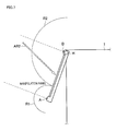
- FIG. 3 is a view schematically illustrating a position of an antenna mounted on manipulation panel 20 .
- FIG. 4 is a view illustrating a principle of an electrostatic capacitance sensor.
- FIG. 5 is a control flowchart of a transition to a power saving mode and a return from the power saving mode in an embodiment of the present invention.
- FIG. 6 is a view schematically illustrating detection ranges of antennas A and B and an approach direction of a manipulation finger when manipulation panel 20 has an angle ⁇ of 90 degrees.
- FIG. 7 is a view schematically illustrating the detection ranges of the antennas A and B and the approach direction of the manipulation finger when manipulation panel 20 has angles ⁇ of 46 degrees to 89 degrees.
- FIG. 8 is a view schematically illustrating the detection ranges of the antennas A and B and the approach direction of the manipulation finger when manipulation panel 20 has the angle ⁇ of 0 degree.
- FIG. 9 is a view of a subroutine of processing in S 504 in FIG. 5 .
- FIG. 10 is a view schematically illustrating the detectable range of the antennas A and B when manipulation panel 20 is in a horizontal state.
- FIG. 11 is a view schematically illustrating a first human body detecting distance table.
- FIG. 12 is a view of a subroutine of processing in S 506 in FIG. 5 .
- FIG. 13 is a view schematically illustrating a second human body detecting distance table.
- FIG. 14 is a view schematically illustrating a third human body detecting distance table.
- FIG. 15 is a view schematically illustrating a relationship between a sheet discharge unit 135 and detectable ranges of antennas 131 and 132 .
- FIG. 16 is a view schematically illustrating a fourth human body detecting distance table.
- FIG. 17 is a view schematically illustrating a relationship between an authentication device 195 and detectable ranges of antennas 191 and 192 .
- FIG. 18 is a view schematically illustrating a fifth human body detecting distance table.
- FIG. 19 is a control flowchart of the transition to the power saving mode and the return from the power saving mode in a fourth modification of the present invention.
- an image forming apparatus forms an image by an electrophotographic system or an electrostatic recording system.
- the image forming apparatus may be an MFP having a scanner function, a facsimile function, a copying function, a function as a printer, a data communication function, and a server function, a facsimile machine, a copying machine, or printers.
- a copying machine 1 (digital multi function peripheral) that is the image forming apparatus of the present embodiment includes a main controller 10 , a manipulation panel 20 , a power supply controller 30 , a power supply 40 , an image reader 50 , an image forming unit 60 , a manipulation panel angle monitor 70 , an output sheet detector (sheet discharge port monitor) 80 , and an authentication device detector 90 .
- Main controller 10 collectively controls each unit of copying machine 1 .
- Main controller 10 includes a CPU 11 that executes various control programs, a ROM (Read Only Memory) 12 in which a control program to control an operation of copying machine 1 is stored, a RAM (Random Access Memory) 13 that is a working memory of CPU 11 , and a sensor control circuit 14 that controls sensitivity of a sensor 23 .
- ROM Read Only Memory
- RAM Random Access Memory
- Manipulation panel 20 includes an LCD (Liquid Crystal Display) driving circuit 21 , a manipulation panel CPU 22 , and sensor 23 .
- LCD driving circuit 21 drives an LCD screen of a touch panel 25 (see FIG. 2 ) under the control of manipulation panel CPU 22 .
- Manipulation panel CPU 22 controls the operation of manipulation panel 20 based on an instruction from main controller 10 .
- sensor 23 is a semiconductor control sensor. In the case where an operating state of copying machine 1 is in a power saving mode, sensor 23 detects (senses) an approach of a human body in a noncontact manner. Sensor 23 is connected to sensor control circuit 14 .
- Image reader 50 performs processing of reading a document on a document holder.
- Image forming unit 60 performs image forming processing based on image data read by image reader 50 .
- Manipulation panel angle monitor 70 is attached to a hinge H (see FIG. 2 ) for changing an angle ⁇ of manipulation panel 20 to monitor the angle of the manipulation panel.
- Output sheet detector 80 detects existence or non-existence of an output to a sheet discharge unit 135 (see FIG. 15 ) of copying machine 1 .
- Authentication device detector 90 detects whether an authentication device 195 (see FIG. 17 ) is placed in copying machine 1 .
- Power supply controller 30 controls power feeding from power supply 40 to such units of copying machine 1 as LCD driving circuit 21 and manipulation panel CPU 22 .
- Power supply controller 30 can change the operating state (a controls state of power supply controller 30 ) of copying machine 1 between a normal mode and a power saving mode having power consumption lower than that of the normal mode. The power is fed to all circuits in the normal mode, and the power feeding to some circuits is stopped in the power saving mode. The power is fed to main controller 10 from power supply 40 even in the power saving mode.
- main controller 10 controls power supply controller 30 to cause the operating state of copying machine 1 to transition from the normal mode to the power saving mode.
- main controller 10 adjusts antenna sensitivity (detection range) of sensor 23 by angle ⁇ of manipulation panel 20 monitored by manipulation panel angle monitor 70 .
- FIG. 2 is a view schematically illustrating a configuration of an appearance of manipulation panel 20 .
- manipulation panel 20 includes various manipulation keys 24 and touch panel 25 .
- Manipulation key 24 includes a numerical keypad, a start key, a function setting key and the like.
- Touch panel 25 has a display function of displaying a setting content or an operating state of copying machine 1 and an input receiving function of receiving a user input through touch panel 25 .
- manipulation panel 20 On a backside (a surface on an opposite side to a surface in FIG. 2 ), manipulation panel 20 is fixed to a main body (apparatus body) of copying machine 1 with hinge H interposed therebetween. Therefore, angle ⁇ of manipulation panel 20 can be changed.
- FIG. 3 is a view schematically illustrating a position of the antenna mounted on manipulation panel 20 .
- sensor 23 includes a plurality of rod-shaped antennas (sensor antennas and human body sensors) 401 to 409 disposed at positions different from each other in manipulation panel 20 .
- antennas 401 to 409 are electrostatic capacitance sensors disposed so as to surround an outer periphery of the surface (the surface in FIG. 3 ) of manipulation panel 20 .
- antennas 401 and 402 extend in a horizontal direction.
- antennas 403 and 404 extend in a vertical direction.
- antennas 405 and 406 extend in the horizontal direction.
- antenna 407 extends in the vertical direction.
- Antennas 402 and 407 to 409 are disposed so as to surround an outer periphery of a numerical keypad 24 a that is one of manipulation keys 24 .
- antenna 402 extends in the horizontal direction.
- antenna 407 extends in the vertical direction.
- antenna 408 extends in the vertical direction.
- antenna 409 extends in the horizontal direction.
- antennas 401 to 409 are disposed around touch panel 25 and manipulation key 24 , which allows sensor 23 to detect a manipulation finger of the user who manipulates touch panel 25 and manipulation key 24 .
- sensor 23 is an electrostatic capacitance sensor. Sensor 23 detects the approach of the manipulation finger of the user to antennas 401 to 409 based on a change in electrostatic capacitance between the manipulation finger of the user and antennas 401 to 409 . It is to be noted that the positions and the number of antennas 401 to 409 are illustrated in FIG. 3 by way of example, but there is no limitation to the positions and the number of antennas 401 to 409 .
- FIG. 4 is a view illustrating a principle of the electrostatic capacitance sensor.
- sensor 23 includes a sensor body 23 a and an antenna 28 .
- Antenna 28 corresponds to each of antennas 401 to 409 in FIG. 3 .
- Antenna 28 is connected to sensor body 23 a .
- Sensor body 23 a has a detection capacitance Cr and a reference capacitance Co therein.
- Antenna 28 constitutes a capacitance Cp (finger-antenna capacitance Cp) with a manipulation finger F of the user. Capacitance Cp increases when manipulation finger F approaches antenna 28 .
- Sensor control circuit 14 can set the sensitivity of antenna 28 by adjusting each of detection capacitance Cr and reference capacitance Co.
- an infrared sensor may be used in addition to the electrostatic capacitance sensor 23 .
- main controller 10 sets a detection range of the human body based on the state of copying machine 1 . Specifically, main controller 10 sets the detection range based on at least one of angle ⁇ of manipulation panel 20 , the existence or non-existence of the output to the sheet discharge unit of copying machine 1 , and the existence or non-existence of the placement of the authentication device in copying machine 1 .
- Main controller 10 sets the detection range by the sensitivity of each of antennas 401 to 409 and a kind of a human body detecting distance table used.
- main controller 10 When sensor 23 detects that the human body approaches the detection range set by main controller 10 , main controller 10 returns the operating state of copying machine 1 from the power saving mode to the normal mode. When manipulation panel CPU 22 detects that manipulation panel 20 is manipulated, main controller 10 returns the operating state of copying machine 1 from the power saving mode to the normal mode.
- FIG. 5 is a control flowchart of the transition to the power saving mode and the return from the power saving mode in an embodiment of the present invention.
- main controller 10 starts a time count of a time necessary to transition to a previously-set power saving mode (S 500 ), and main controller 10 determines whether the manipulation is performed to various manipulation keys 24 or touch panel 25 of manipulation panel 20 (S 501 ).
- main controller 10 proceeds to the processing in S 500 .
- main controller 10 determines whether the time necessary to transition to the power saving mode is up (S 502 ).
- main controller 10 checks angle ⁇ of manipulation panel 20 using manipulation panel angle monitor 70 (S 503 ). Subsequently, main controller 10 adjusts the sensitivity of each of antennas 401 to 409 according to angle ⁇ (S 504 ), and main controller 10 proceeds to processing in S 505 . On the other hand, when the time necessary to transition to the power saving mode is not up (No in S 502 ), main controller 10 proceeds to the processing in S 501 .
- step S 505 main controller 10 controls power supply controller 30 to cause the operating state of copying machine 1 to transition to the power saving mode (S 505 ), and main controller 10 monitors sensor 23 (S 506 ). Main controller 10 determines whether sensor 23 detects the human body (S 507 ).
- step S 507 when sensor 23 detects the human body (Yes in S 507 ), main controller 10 releases the power saving mode to return the operating state of copying machine 1 to the normal mode (S 508 ), and main controller 10 ends the processing. On the other hand, when sensor 23 does not detect the human body (No in S 507 ), main controller 10 goes to the processing in S 506 .
- main controller 10 may set the sensitivity of each of antennas 401 to 409 based on angle ⁇ of manipulation panel 20 .
- FIG. 6 is a view schematically illustrating the detection ranges of antennas A and B and an approach direction of the manipulation finger when manipulation panel 20 has angle ⁇ of 90 degrees.
- an antenna that corresponds to antennas 401 and 402 provided in the upper portion of manipulation panel 20 in FIG. 3 may be referred to as an antenna B
- an antenna that corresponds to antennas 405 and 406 provided in the lower portion of manipulation panel 20 in FIG. 3 may be referred to as an antenna A.
- angle ⁇ of manipulation panel 20 is defined as an angle formed between a horizontal plane (horizontal direction) and a direction in which the surface of manipulation panel 20 extends.
- hinge H extends in the direction perpendicular to a paper surface, and angle ⁇ is 90 degrees.
- Angle ⁇ of manipulation panel 20 can be changed in a range of 0 degree to 90 degrees.
- the manipulation finger of the user usually approaches manipulation panel 20 along the direction indicated by an arrow AR 1 , and the human body of the user is detected in a range (hereinafter sometimes referred to as a detectable range) R 2 where antenna B can detect the distance.
- main controller 10 decreases the sensitivity of other antennas including antenna A while locally increasing the sensitivity of antenna B, so that the false detection of antenna A is prevented.
- FIG. 7 is a view schematically illustrating the detection ranges of antennas A and B and the approach direction of the manipulation finger when manipulation panel 20 has angles ⁇ of 46 degrees to 89 degrees.
- the manipulation finger of the user in the case where manipulation panel 20 has angles ⁇ of 46 degrees to 89 degrees, the manipulation finger of the user usually approaches manipulation panel 20 along the direction indicated by an arrow AR 2 , and the human body of the user is detected on a slightly lower side (a central portion of manipulation panel 20 ) in detectable range R 2 of antenna B. Because there is the low possibility of detecting the human body of the user in detectable range R 1 of antenna A, antenna A easily generates the false detection when detectable range R 1 becomes wider.
- main controller 10 increases the sensitivity of the antenna located between (the central portion of manipulation panel 20 ) antennas A and B compared with the case that manipulation panel 20 has angle ⁇ of 90 degrees.
- the sensitivity of antenna A remains decreased to prevent the false detection of antenna A.
- FIG. 8 is a view schematically illustrating the detection ranges of antennas A and B and the approach direction of the manipulation finger when manipulation panel 20 has angle ⁇ of 0 degree.
- manipulation panel 20 has angle ⁇ of 0 degree (manipulation panel 20 is in the horizontal state, or the display surface of manipulation panel 20 is horizontal)
- the lower portion of manipulation panel 20 projects toward a pathway side (an outside of copying machine 1 ), and detectable range R 1 of antenna A hangs over the pathway side. Therefore, when detectable range R 1 becomes wider, there is a high possibility of falsely detecting the human body that passes by the neighborhood of copying machine 1 . Accordingly, in the case where manipulation panel 20 has angle ⁇ of 0 degree, main controller 10 locally decreases the sensitivity of antenna A.
- FIG. 9 is a view of a subroutine of the processing in S 504 in FIG. 5 .
- main controller 10 determines whether manipulation panel 20 has angle ⁇ of 0 degree (the horizontal state) (S 601 ).
- main controller 10 When manipulation panel 20 has angle ⁇ of 0 degree (Yes in S 601 ), main controller 10 locally decreases the sensitivity of the antenna (antenna A) in the lower portion of manipulation panel 20 . Specifically, main controller 10 sets the sensitivity of each of antennas 401 , 402 , 403 , 407 , and 408 to strong, and sets the sensitivity of each of antennas 404 , 405 , 406 , and 409 to weak (S 602 ). Then main controller 10 returns to a main routine. On the other hand, when manipulation panel 20 does not have angle ⁇ of 0 degree (No in S 601 ), main controller 10 determines whether manipulation panel 20 has angle ⁇ of 90 degrees (the perpendicular state) (S 603 ).
- main controller 10 When manipulation panel 20 has angle ⁇ of 90 degrees (Yes in S 603 ), main controller 10 locally increases the sensitivity of the antenna (antenna B) in the upper portion of manipulation panel 20 . Specifically, main controller 10 sets the sensitivity of each of antennas 401 and 402 to strong, and sets the sensitivity of each of antennas 403 , 404 , 405 , 406 , 407 , 408 , and 409 to weak (S 604 ). Then main controller 10 returns to the main routine. On the other hand, when manipulation panel 20 does not have angle ⁇ of 90 degrees (No in S 603 ), main controller 10 determines whether manipulation panel 20 has angles ⁇ of 1 degree to 44 degrees (S 605 ).
- main controller 10 decreases the sensitivity of the antenna in the central portion of manipulation panel 20 compared with the case where manipulation panel 20 has angle ⁇ of 0 degree. Specifically, main controller 10 sets the sensitivity of each of antennas 401 , 402 , 403 , and 407 to strong, sets the sensitivity of each of antennas 408 and 409 to medium, and sets the sensitivity of each of antennas 404 , 405 , and 406 to weak (S 606 ). Then main controller 10 returns to the main routine. On the other hand, when manipulation panel 20 has angles ⁇ of 1 degree to 44 degrees (No in S 605 ), main controller 10 determines whether manipulation panel has angles ⁇ of 46 degrees to 89 degrees (S 607 ).
- main controller 10 increases the sensitivity of the antenna in the central portion of manipulation panel 20 compared with the case where manipulation panel 20 has angle ⁇ of 90 degrees. Specifically, main controller 10 sets the sensitivity of each of antennas 401 and 402 to strong, sets the sensitivity of each of antennas 403 , 404 , 407 , and 408 to medium, and sets the sensitivity of each of antennas 405 , 406 , and 409 to weak (S 608 ). Then main controller 10 returns to the main routine. On the other hand, when manipulation panel 20 does not have angles ⁇ of 46 degree to 89 degrees (No in S 607 ), main controller 10 proceeds to the processing in S 601 .
- the method for setting (adjusting) the sensitivity of each of antennas 401 to 409 is not limited to the present embodiment.
- the sensitivity of each of antennas 401 to 409 may be decided based on another condition (for example, the existence or non-existence of the output to sheet discharge unit 135 (see FIG. 15 ) and the existence or non-existence of the placement of authentication device 195 (see FIG. 17 ) in copying machine 1 ) in addition to angle ⁇ of manipulation panel 20 .
- FIG. 10 is a view schematically illustrating the detectable range of antennas A and B when manipulation panel 20 is in the horizontal state.
- curved lines A 1 to A 6 or B 1 to B 6 indicate boundary lines on each of which the distance detected by antenna A or B changes.
- each of antennas A and B placed in manipulation panel 20 detects the distance from the antenna to human body in a stepwise manner.
- Antenna A (the antenna in front of the touch panel) can detect the distance to the human body at six stages of distances A 1 to A 6 .
- antenna A does not detect the distance to the human body.
- antenna A detects the distance to the human body as distance A 1 .
- antenna A detects the distance to the human body as distance A 2 .
- antenna A detects the distance to the human body as distance A 3 .
- antenna A detects the distance to the human body as distance A 4 . In the case where the human body falls within a range of boundary line A 5 to boundary line A 6 , antenna A detects the distance to the human body as distance A 5 . In the case where the human body is located within boundary line A 6 , antenna A detects the distance to the human body as distance A 6 . In this case, the detectable range of antenna A is located within boundary line A 1 .
- Antenna B (the antenna at the back of the touch panel) can detect the distance to the human body at six stages of distances B 1 to B 6 .
- antenna B does not detect the distance to the human body.
- antenna B detects the distance to the human body as distance B 1 .
- antenna B detects the distance to the human body as distance B 2 .
- antenna B detects the distance to the human body as distance B 3 .
- antenna B detects the distance to the human body as distance B 4 . In the case where the human body falls within a range of boundary line B 5 to boundary line B 6 , antenna B detects the distance to the human body as distance B 5 . In the case where the human body is located within boundary line B 6 , antenna B detects the distance to the human body as distance B 6 . In this case, the detectable range of antenna B is located within boundary line B 1 . Distances A 1 to A 6 and B 1 to B 6 each can be set by the sensitivity of each of antennas A and B.
- the detectable range of antenna A reaches the pathway (the left side in FIG. 10 ). Therefore, in the case where the range where the detectable range (in boundary line A 1 ) of antenna A and the detectable range (in boundary line B 1 ) of antenna B are added is set to the detection range of sensor 23 , antenna A falsely detect the human body to release the power saving mode when the human body merely passes by copying machine 1 .
- main controller 10 determines whether the human body approaches the detection range of sensor 23 based on a combination of the distances detected by antennas A and B using the human body detecting distance table indicating a relationship between the distances detected by antennas A and B and the detection range of sensor 23 .
- the human body detecting distance table is stored in ROM 12 .
- FIG. 11 is a view schematically illustrating a first human body detecting distance table.
- the human body detecting distance table illustrates the relationship between the distances detected by antennas A and B and the detection range. Specifically, the human body detecting distance table illustrates whether crossing points of boundary lines A 1 to A 6 having variable distances detected by antenna A and boundary lines B 1 to B 6 having variable distances detected by antenna B fall within the detection range, respectively.
- a line SF connecting a crossing point PO 1 of boundary line A 1 and boundary line B 1 , a crossing point PO 2 of boundary line A 2 and boundary line B 2 , a crossing point PO 3 of boundary line A 3 and boundary line B 3 , a crossing point PO 4 of boundary line A 4 and boundary line B 4 , a crossing point PO 5 of boundary line A 5 and boundary line B 5 , and a crossing point PO 6 of boundary line A 6 and boundary line B 6 is a boundary of the detection range of sensor 23 .
- An area located on the main body side of copying machine 1 (apparatus body side) of line SF is the detection range of sensor 23 .
- main controller 10 determines that the human body approaches the detection range, and releases the power saving mode.
- an area located on the pathway side of the line SF is the outside of the detection range of sensor 23 .
- main controller 10 does not release the power saving mode even if antenna A or B can detect the distance to the human body.
- main controller 10 detects that the human body approaches the detection range of sensor 23 , and returns the operating state of copying machine 1 from the power saving mode to the normal mode.
- main controller 10 does not detect that the human body approaches the detection range of sensor 23 , and maintains the operating state of copying machine 1 in the power saving mode.
- line SF is set in a plane that extends toward a vertical direction from the lower portion (in FIG. 10 , an end portion on the outer periphery side of copying machine 1 , and a portion projecting toward the pathway side of manipulation panel 20 ) of manipulation panel 20 as illustrated in FIG. 10 . Therefore, the detection range can be set onto the main body side of copying machine 1 of the plane.
- the human body detecting distance table is prepared such that an area on the main body side of copying machine 1 of the portion projecting toward the pathway side of manipulation panel 20 becomes the detection distance of sensor 23 , allowing the prevention of the false detection of antenna A placed in the portion projecting toward the pathway side of manipulation panel 20 .
- the human body detecting distance table may be set more finely by finely dividing the detection distance of antenna A or B.
- FIG. 12 is a view of a subroutine of the processing in S 506 in FIG. 5 .
- main controller 10 detects the distance to the human body using antennas A and B (S 701 ). By use of the human body detecting distance table, main controller 10 determines whether the position of the human body is located at the crossing point that is the boundary between the detection ranges of sensor 23 based on the detection results of antennas A and B (S 703 ).
- main controller 10 determines that sensor 23 detects the human body (S 705 ), and main controller 10 returns to the main routine.
- main controller 10 determines that sensor 23 does not detect the human body (S 707 ), and main controller 10 returns to the main routine.
- the method for setting the position or the detectable range of each antenna is not limited to the present embodiment.
- the detection range of sensor 23 may arbitrarily be set, but the detection range is not limited to the area on the main body side of copying machine 1 of the portion projecting toward the pathway side of manipulation panel 20 .
- the angle information on manipulation panel 20 and the detection information of the human body sensor are combined to determine whether the power saving mode is released, so that the false release of the power saving mode can be prevented in the case where a person who has no intention to release the power saving mode approaches copying machine 1 .
- only one human body detecting distance table is stored in ROM 12 .
- the case where a plurality of human body detecting distance tables are stored in ROM 12 will be described in a first modification.
- FIG. 13 is a view schematically illustrating a second human body detecting distance table.
- the second human body detecting distance table differs from the human body detecting distance table in FIG. 11 in that crossing point PO 1 of boundary line A 1 and boundary line B 1 , crossing point PO 2 of boundary line A 2 and boundary line B 2 , crossing point PO 3 of boundary line A 3 and boundary line B 3 , crossing point PO 4 of boundary line A 4 and boundary line B 4 , crossing point PO 5 of boundary line A 5 and boundary line B 5 , and crossing point PO 6 of boundary line A 6 and boundary line B 6 are each located out of the detection range of sensor 23 .
- the human body detecting distance table in FIG. 11 and the human body detecting distance table in FIG. 13 are stored in ROM 12 .
- main controller 10 selects the human body detecting distance table used to detect the human body using sensor 23 from the tables stored in ROM 12 based on angle ⁇ of manipulation panel 20 .
- main controller 10 selects the human body detecting distance table in FIG. 11 in the case where manipulation panel 20 has angle ⁇ of 0 degree (manipulation panel 20 is in the horizontal state), and main controller 10 selects the human body detecting distance table in FIG. 13 in the case where manipulation panel 20 does not have angle ⁇ of 0 degree.
- the human body detecting distance table in FIG. 11 is the table for the case where manipulation panel 20 is in the horizontal state.
- Any number of human body detecting distance tables may be stored in ROM 12 , and at least three human body detecting distance tables may be stored in ROM 12 .
- the human body detecting distance table that is selected in the case where manipulation panel 20 does not have angle ⁇ of 0 degree may be one except the human body detecting distance table in FIG. 13 .
- antennas A and B detect the distance to the human body in the stepwise manner.
- the case where antennas A and B continuously detect the distance to the human body will be described in a second modification.
- FIG. 14 is a view schematically illustrating a third human body detecting distance table.
- the third human body detecting distance table may be used in the case where antennas A and B continuously detect the distance to the human body.
- the third human body detecting distance table illustrates whether a combination of the range including the distance to the human body detected by antenna A and the range including the distance to the human body detected by antenna B falls within the detection range.
- the range of the distance detected by antenna A is divided into three ranges: a range of distances D 1 and D 2 , a range of distances D 2 and D 3 , and a range of distances D 3 and D 4 .
- the range of distance detected by antenna B is divided into three ranges: a range of distances D 11 and D 12 , a range of distances D 12 and D 13 , and a range of distances D 13 and D 14 .
- main controller 10 determines that the human body approaches the detection range, and releases the power saving mode.
- main controller 10 determines that the human body does not approach the detection range, and does not release the power saving mode.
- FIG. 15 is a view schematically illustrating a relationship between sheet discharge unit 135 and the detectable ranges of antennas 131 and 132 .
- copying machine 1 includes sheet discharge unit 135 that is disposed in the central portion thereof.
- the output (sheet on which the image is printed) is discharged from the main body of copying machine 1 to sheet discharge unit 135 .
- Angle ⁇ of manipulation panel 20 can be changed.
- FIG. 15 illustrates the state in which manipulation panel 20 is in the perpendicular state (angle ⁇ of 90 degrees).
- Sensor 23 includes a plurality of rod-shaped antennas 131 and 132 that are disposed at positions different from each other in manipulation panel 20 .
- Antennas 131 and 132 are disposed at the outer periphery in the surface (the surface in FIG. 15 ) of manipulation panel 20 .
- Antenna 131 extends in the horizontal direction in the lower left portion of manipulation panel 20 in FIG. 15 .
- Antenna 132 extends in the horizontal direction in the lower portion of manipulation panel 20 in FIG. 15 .
- Antenna 131 can detect the distance to the human body at five stages of distances A 1 to A 5 .
- Antenna 132 can detect the distance to the human body at five stages of distances B 1 to B 5 .
- Distances A 1 to A 5 and B 1 to B 5 can be set by the sensitivity of each of antennas 131 and 132 .
- main controller 10 selects the human body detecting distance table in which the left side portion of manipulation panel 20 close to sheet discharge unit 135 is out of the detection range of sensor 23 . Therefore, the false detection of the arm of the user who collects the output can be prevented.
- FIG. 16 is a view schematically illustrating a fourth human body detecting distance table.
- main controller 10 selects the fourth human body detecting distance table in the case where the angle ⁇ of manipulation panel 20 is in the state except the horizontal state while output sheet detector 80 detects that the output exists on sheet discharge unit 135 .
- the fourth human body detecting distance table illustrates whether the crossing point of each of boundary lines A 1 to A 5 having the variable distance detected by antenna 131 and each of boundary lines B 1 to B 5 having the variable distance detected by antenna 132 falls within the detection range.
- line SF connecting crossing point PO 1 of boundary line A 1 and boundary line B 1 , crossing point PO 2 of boundary line A 2 and boundary line B 2 , crossing point PO 3 of boundary line A 3 and boundary line B 3 , crossing point PO 4 of boundary line A 4 and boundary line B 4 , and crossing point PO 5 of boundary line A 5 and boundary line B 5 is the boundary of the detection range of sensor 23 .
- the area on the side (the upper right side in FIG. 15 ) that is far away from sheet discharge unit 135 with respect to line SF is in the detection range of sensor 23 .
- main controller 10 determines that the human body approaches the detection range, and releases the power saving mode.
- the area on the side (the left side portion of manipulation panel 20 close to sheet discharge unit 135 ) close to sheet discharge unit 135 with respect to line SF is out of the detection range of sensor 23 .
- main controller 10 does not release the power saving mode even if antenna 131 or 132 can detect the distance to the human body.
- the human body detecting distance table may be set more finely by finely dividing the detection distance of antenna 131 or 132 .
- the human body detecting distance table in FIG. 16 may be used irrespective of angle ⁇ of manipulation panel 20 in the case where the output exists on sheet discharge unit 135 of copying machine 1 .
- FIG. 17 is a view schematically illustrating a relationship between authentication device 195 and the detectable ranges of antennas 191 and 192 .
- copying machine 1 includes authentication device 195 disposed in a right end portion in FIG. 17 .
- Authentication device 195 authenticates the user who uses copying machine 1 .
- Sensor 23 includes a plurality of rod-shaped antennas 191 and 192 disposed at positions different from each other in manipulation panel 20 .
- Antennas 191 and 192 are disposed at the outer periphery in the surface (the surface in FIG. 17 ) of manipulation panel 20 .
- Antenna 191 extends in the horizontal direction in the lower portion of manipulation panel 20 in FIG. 17 .
- Antenna 192 extends in the horizontal direction in the lower portion of manipulation panel 20 in FIG. 17 .
- Antenna 191 can detect the distance to the human body at three stages of distances A 1 to A 3 .
- Antenna 192 can detect the distance to the human body at three stages of distances B 1 to B 3 .
- Distances A 1 to A 3 and B 1 to B 3 can be set by the sensitivity of each of antennas 191 and 192 .
- authentication device 195 In the case where authentication device 195 is placed in copying machine 1 , it is necessary for the user to perform an authentication manipulation using authentication device 195 before copying machine 1 is manipulated.
- antenna 191 or 192 falsely detects the arm of the user who passes by the right side portion of manipulation panel 20 close to authentication device 195 , resulting in the risk of releasing the power saving mode.
- main controller 10 selects the human body detecting distance table in which the right side portion of manipulation panel 20 close to authentication device 195 is out of the detection range of sensor 23 . Therefore, the false detection of the arm of the user who performs the authentication manipulation can be prevented.
- FIG. 18 is a view schematically illustrating a fifth human body detecting distance table.
- main controller 10 selects the fifth human body detecting distance table in the case where authentication device detector 90 detects that authentication device 195 is placed.
- the fifth human body detecting distance table illustrates whether the crossing point of each of boundary lines A 1 to A 3 having the variable distance detected by antenna 191 and each of boundary lines B 1 to B 3 having the variable distance detected by antenna 192 falls within the detection range.
- line SF connecting crossing point PO 1 of boundary line A 1 and boundary line B 1 , crossing point PO 2 of boundary line A 2 and boundary line B 2 , and crossing point PO 3 of boundary line A 3 and boundary line B 3 is the boundary of the detection range of sensor 23 .
- the area on the side (the left side in FIG.
- main controller 10 determines that the human body approaches the detection range, and releases the power saving mode.
- the area on the side (the right side portion of manipulation panel 20 close to authentication device 195 ) close to authentication device 195 with respect to line SF is out of the detection range of sensor 23 .
- main controller 10 does not release the power saving mode even if antenna 191 or 192 can detect the distance to the human body.
- the human body detecting distance table may be set more finely by finely dividing the detection distance of antenna 191 or 192 .
- the position at which the antenna is placed or the detection range of sensor 23 is set based on the existence or non-existence of the output to sheet discharge unit 135 of copying machine 1 or the existence or non-existence of the placement of authentication device 195 in copying machine 1 . Therefore, in the case where a person who has no intention to release the power saving mode approaches manipulation panel 20 , the false detection of the human body of the person can be prevented, and the unnecessary release of the power saving mode can be prevented.
- FIG. 19 is a control flowchart of the transition to the power saving mode and the return from the power saving mode in a fourth modification of the present invention.
- main controller 10 starts the time count of the time necessary to transition to the previously-set power saving mode (S 1500 ), and main controller 10 determines whether the manipulation is performed to various manipulation keys 24 or touch panel 25 of manipulation panel 20 (S 1501 ).
- main controller 10 determines whether the time necessary to transition to the power saving mode is up (S 1502 ).
- main controller 10 checks the detection state of output sheet detector 80 (S 1503 ), and main controller 10 determines whether the output exists on sheet discharge unit 135 (S 1504 ).
- main controller 10 selects the fourth human body detecting distance table in FIG. 16 (S 1505 ), and main controller 10 proceeds to processing in S 1506 .
- main controller 10 checks the detection state of authentication device detector 90 , and determines whether authentication device 195 is mounted on (placed in) copying machine 1 (S 1510 ).
- main controller 10 selects the fifth human body detecting distance table in FIG. 18 (S 1511 ), and main controller 10 proceeds to the processing in S 1506 .
- main controller 10 selects the first human body detecting distance table in FIG. 11 (S 1512 ), and main controller 10 proceeds to the processing in S 1506 .
- Main controller 10 controls power supply controller 30 to cause the operating state of copying machine 1 to transition to the power saving mode (S 1506 ), and main controller 10 monitors sensor 23 (S 1507 ). In S 1507 , for example, the subroutine in FIG. 12 may be performed. Subsequently, main controller 10 determines whether sensor 23 detects the human body (S 1508 ).
- main controller 10 When sensor 23 detects the human body (Yes in S 1508 ), main controller 10 releases the power saving mode to return the operating state of copying machine 1 to the normal mode (S 1509 ), and main controller 10 ends the processing. On the other hand, when sensor 23 does not detect the human body (No in S 1508 ), main controller 10 proceeds to the processing in S 1507 .
- the image forming apparatus that improves the reliability of the release of the power saving mode can be provided.
- the above embodiment relates to the image forming apparatus that can release the power saving mode using the low-power-consumption semiconductor control sensor that performs proximity detection in the technology of releasing the power saving mode (energy saving mode).
- the energy saving releasing sensor is provided around the manipulation panel, and the detection range (non-contact position) where the release of the energy saving of the sensor is detected is changed according to the angle of the manipulation panel, the existence or non-existence of the output to the sheet discharge unit, and the existence or non-existence of the placement of the authentication device in the image forming apparatus. Therefore, the human body is hardly detected when the person merely stands in front of the apparatus.
- the person who has no intention to release the power saving mode approaches the manipulation panel such that a person passes by in front of the image forming apparatus or such that a service person performs maintenance of the image forming apparatus, the false detection of the human body of the person can be prevented, and the reliability of the release of the power saving mode can be improved.
- the sensitivity of each antenna is set based on the angle of the manipulation panel, allowing the detection range of the sensor to be easily set according to the state of the image forming apparatus.
- Whether the human body approaches the detection range is determined using the table based on the distances detected by the two sensors, allowing the detection range of the sensor to be easily set using the table.
- the detection range of the sensor can easily be set according to the state of the image forming apparatus by selecting the table to be used from the plurality of tables.
- the detection range may be set based on at least one of the angle of the manipulation panel of the image forming apparatus, the existence or non-existence of the output to the sheet discharge unit of the image forming apparatus, and the existence or non-existence of the placement of the authentication device in the image forming apparatus, and the sensitivity of the antenna may be invariable irrespective of the state of the image forming apparatus.
- the sensitivity of the antenna may be set according to the existence or non-existence of the output sheet to the sheet discharge unit or the existence or non-existence of the placement of the authentication device.
- the processing in the above embodiment may be performed by software or performed using a hardware circuit.
- a program that performs the processing in the above embodiment can be provided, or the program may be provided to the user while recorded in recording medium, such as a CD-ROM, a flexible disk, a hard disk, a ROM, a RAM, and a memory card.
- the program is executed by computers, such as the CPU.
- the program may be downloaded in the apparatus through communication lines, such as the Internet.
Applications Claiming Priority (2)
| Application Number | Priority Date | Filing Date | Title |
|---|---|---|---|
| JP2011253487A JP5573822B2 (ja) | 2011-11-21 | 2011-11-21 | 画像形成装置、画像形成装置の制御方法、および画像形成装置の制御プログラム |
| JP2011-253487 | 2011-11-21 |
Publications (2)
| Publication Number | Publication Date |
|---|---|
| US20130128298A1 US20130128298A1 (en) | 2013-05-23 |
| US10074043B2 true US10074043B2 (en) | 2018-09-11 |
Family
ID=48426583
Family Applications (1)
| Application Number | Title | Priority Date | Filing Date |
|---|---|---|---|
| US13/681,912 Active 2033-01-12 US10074043B2 (en) | 2011-11-21 | 2012-11-20 | Image forming apparatus capable of changing operating state |
Country Status (2)
| Country | Link |
|---|---|
| US (1) | US10074043B2 (ja) |
| JP (1) | JP5573822B2 (ja) |
Families Citing this family (30)
| Publication number | Priority date | Publication date | Assignee | Title |
|---|---|---|---|---|
| EP2713213B1 (en) * | 2012-09-03 | 2022-01-19 | Konica Minolta, Inc. | Image forming apparatus, power control method, and recording medium |
| JP6128781B2 (ja) * | 2012-09-06 | 2017-05-17 | キヤノン株式会社 | 画像形成装置及び画像形成装置の制御方法 |
| US20140160505A1 (en) * | 2012-12-03 | 2014-06-12 | Canon Kabushiki Kaisha | Image processing apparatus, method of controlling image processing apparatus, and program |
| JP6184084B2 (ja) * | 2012-12-03 | 2017-08-23 | キヤノン株式会社 | 画像処理装置、画像処理装置の制御方法、及びプログラム |
| CN107861607B (zh) * | 2012-12-05 | 2020-10-20 | 佳能株式会社 | 图像形成装置及图像形成装置的控制方法 |
| JP5885645B2 (ja) * | 2012-12-05 | 2016-03-15 | 京セラドキュメントソリューションズ株式会社 | 情報処理装置、認証方法 |
| JP2014124833A (ja) * | 2012-12-26 | 2014-07-07 | Kyocera Document Solutions Inc | 画像形成装置 |
| JP6161417B2 (ja) * | 2013-06-14 | 2017-07-12 | キヤノン株式会社 | 画像形成装置、画像形成装置の制御方法、及びプログラムを記録した記録媒体 |
| JP2015005905A (ja) * | 2013-06-21 | 2015-01-08 | キヤノン株式会社 | 画像形成装置、画像形成装置の制御方法、及びプログラム |
| JP6639069B2 (ja) * | 2013-06-21 | 2020-02-05 | キヤノン株式会社 | 画像形成装置及び画像形成装置の制御方法 |
| JP6044472B2 (ja) * | 2013-06-28 | 2016-12-14 | 富士ゼロックス株式会社 | 情報処理装置及びプログラム |
| JP6044471B2 (ja) * | 2013-06-28 | 2016-12-14 | 富士ゼロックス株式会社 | 電力制御装置、画像処理装置及びプログラム |
| JP6015589B2 (ja) | 2013-08-09 | 2016-10-26 | 富士ゼロックス株式会社 | 処理装置及びプログラム |
| JP2015041323A (ja) * | 2013-08-23 | 2015-03-02 | 富士ゼロックス株式会社 | 処理装置 |
| JP6027954B2 (ja) * | 2013-08-29 | 2016-11-16 | 京セラドキュメントソリューションズ株式会社 | 画像形成装置 |
| JP6287259B2 (ja) * | 2014-01-27 | 2018-03-07 | 株式会社リコー | 電子機器 |
| JP5934277B2 (ja) * | 2014-03-31 | 2016-06-15 | 京セラドキュメントソリューションズ株式会社 | 操作装置及び位置ズレ調製方法 |
| JP6022524B2 (ja) * | 2014-11-21 | 2016-11-09 | 京セラドキュメントソリューションズ株式会社 | 電子機器 |
| JP6460752B2 (ja) * | 2014-11-26 | 2019-01-30 | シャープ株式会社 | 画像形成装置 |
| JP6137207B2 (ja) * | 2015-01-26 | 2017-05-31 | コニカミノルタ株式会社 | 画像処理装置、その制御方法、およびプログラム |
| JP2016176710A (ja) | 2015-03-18 | 2016-10-06 | 株式会社リコー | 情報処理装置、及び、プログラム |
| JP7196256B2 (ja) * | 2015-07-22 | 2022-12-26 | キヤノン株式会社 | 画像形成装置 |
| JP6950017B2 (ja) * | 2015-07-22 | 2021-10-13 | キヤノン株式会社 | 画像形成装置 |
| JP6670012B2 (ja) | 2015-07-22 | 2020-03-18 | キヤノン株式会社 | 画像形成装置 |
| JP6725368B2 (ja) * | 2015-09-24 | 2020-07-15 | シャープ株式会社 | 画像形成装置 |
| JP6628093B2 (ja) * | 2016-04-28 | 2020-01-08 | コニカミノルタ株式会社 | 画像形成装置 |
| JP6911384B2 (ja) * | 2017-02-28 | 2021-07-28 | コニカミノルタ株式会社 | 画像処理装置 |
| JP6973092B2 (ja) * | 2018-01-10 | 2021-11-24 | コニカミノルタ株式会社 | タッチパネル及び電子機器 |
| JP2021043423A (ja) * | 2019-09-13 | 2021-03-18 | キヤノン株式会社 | 画像形成装置 |
| JP2023030343A (ja) * | 2021-08-23 | 2023-03-08 | 富士フイルムビジネスイノベーション株式会社 | 画像形成装置 |
Citations (14)
| Publication number | Priority date | Publication date | Assignee | Title |
|---|---|---|---|---|
| JPH06242226A (ja) | 1993-02-20 | 1994-09-02 | Ricoh Co Ltd | オペレータ検出方法,オペレータ検出装置,および画像形成装置 |
| JP2002071833A (ja) | 2000-08-31 | 2002-03-12 | Ricoh Co Ltd | 人体検知センサ装置、画像形成装置、人体検知センサ駆動方法及び記憶媒体 |
| JP2004294700A (ja) * | 2003-03-26 | 2004-10-21 | Kyocera Mita Corp | 画像形成装置 |
| US20050185216A1 (en) * | 2004-02-25 | 2005-08-25 | Matsushita Electric Industrial Co., Ltd. | Multifunction apparatus |
| US20080123131A1 (en) * | 2006-11-28 | 2008-05-29 | Konica Minolta Business Technologies, Inc. | Operation Panel Structure |
| US20080170258A1 (en) * | 2007-01-15 | 2008-07-17 | Miho Yamamura | Image forming apparatus |
| US20090232537A1 (en) * | 2008-03-14 | 2009-09-17 | Kenji Ogasawara | Display device and image forming apparatus |
| US20100150600A1 (en) * | 2008-12-17 | 2010-06-17 | Canon Kabushiki Kaisha | Image processing apparatus and method of controlling the same |
| US20100231390A1 (en) | 2009-03-13 | 2010-09-16 | Canon Kabushiki Kaisha | Image processing apparatus |
| US20100277762A1 (en) * | 2009-05-01 | 2010-11-04 | Konica Minolta Business Technologies, Inc. | Image Forming Apparatus |
| JP2011203614A (ja) | 2010-03-26 | 2011-10-13 | Konica Minolta Business Technologies Inc | 操作パネル支持機構、操作パネル組立体、画像形成システム |
| US20120075657A1 (en) * | 2010-09-29 | 2012-03-29 | Brother Kogyo Kabushiki Kaisha | Image recording apparatus |
| US20120212510A1 (en) * | 2011-02-22 | 2012-08-23 | Xerox Corporation | User interface panel |
| JP2013007847A (ja) | 2011-06-23 | 2013-01-10 | Konica Minolta Business Technologies Inc | 画像形成装置、その制御方法およびその制御プログラム |
-
2011
- 2011-11-21 JP JP2011253487A patent/JP5573822B2/ja not_active Expired - Fee Related
-
2012
- 2012-11-20 US US13/681,912 patent/US10074043B2/en active Active
Patent Citations (15)
| Publication number | Priority date | Publication date | Assignee | Title |
|---|---|---|---|---|
| JPH06242226A (ja) | 1993-02-20 | 1994-09-02 | Ricoh Co Ltd | オペレータ検出方法,オペレータ検出装置,および画像形成装置 |
| JP2002071833A (ja) | 2000-08-31 | 2002-03-12 | Ricoh Co Ltd | 人体検知センサ装置、画像形成装置、人体検知センサ駆動方法及び記憶媒体 |
| JP2004294700A (ja) * | 2003-03-26 | 2004-10-21 | Kyocera Mita Corp | 画像形成装置 |
| US20050185216A1 (en) * | 2004-02-25 | 2005-08-25 | Matsushita Electric Industrial Co., Ltd. | Multifunction apparatus |
| US20080123131A1 (en) * | 2006-11-28 | 2008-05-29 | Konica Minolta Business Technologies, Inc. | Operation Panel Structure |
| US20080170258A1 (en) * | 2007-01-15 | 2008-07-17 | Miho Yamamura | Image forming apparatus |
| US20090232537A1 (en) * | 2008-03-14 | 2009-09-17 | Kenji Ogasawara | Display device and image forming apparatus |
| US20100150600A1 (en) * | 2008-12-17 | 2010-06-17 | Canon Kabushiki Kaisha | Image processing apparatus and method of controlling the same |
| US20100231390A1 (en) | 2009-03-13 | 2010-09-16 | Canon Kabushiki Kaisha | Image processing apparatus |
| JP2010217303A (ja) | 2009-03-13 | 2010-09-30 | Canon Inc | 画像処理装置 |
| US20100277762A1 (en) * | 2009-05-01 | 2010-11-04 | Konica Minolta Business Technologies, Inc. | Image Forming Apparatus |
| JP2011203614A (ja) | 2010-03-26 | 2011-10-13 | Konica Minolta Business Technologies Inc | 操作パネル支持機構、操作パネル組立体、画像形成システム |
| US20120075657A1 (en) * | 2010-09-29 | 2012-03-29 | Brother Kogyo Kabushiki Kaisha | Image recording apparatus |
| US20120212510A1 (en) * | 2011-02-22 | 2012-08-23 | Xerox Corporation | User interface panel |
| JP2013007847A (ja) | 2011-06-23 | 2013-01-10 | Konica Minolta Business Technologies Inc | 画像形成装置、その制御方法およびその制御プログラム |
Non-Patent Citations (2)
| Title |
|---|
| Japanese Office Action (Notice of Grounds of Rejection) dated Nov. 12, 2013, issued by the Japanese Patent Office in corresponding Japanese Patent Application No. 2011-253487, and English language translation of Office Action. (5 pages). |
| Tabata et al.; "Image Forming Apparatus"; JP Pub 2004-294700; JP Pub Date Mar. 26, 2004. * |
Also Published As
| Publication number | Publication date |
|---|---|
| JP5573822B2 (ja) | 2014-08-20 |
| US20130128298A1 (en) | 2013-05-23 |
| JP2013108821A (ja) | 2013-06-06 |
Similar Documents
| Publication | Publication Date | Title |
|---|---|---|
| US10074043B2 (en) | Image forming apparatus capable of changing operating state | |
| US9747537B2 (en) | Power controlling device, image processing apparatus, computer readable medium, and power controlling method | |
| US9152261B2 (en) | Display input device, and image forming apparatus including touch panel portion | |
| US20110109937A1 (en) | Image processing apparatus and method of controlling image processing apparatus | |
| US20170374213A1 (en) | Operation unit and image forming apparatus | |
| US10628035B2 (en) | Image processing apparatus, method for controlling the same, and storage medium | |
| US20150006927A1 (en) | Information processing apparatus, information processing method and non-transitory computer readable medium | |
| JP2014171156A (ja) | 通信装置、通信システム | |
| US8755090B2 (en) | Image reading apparatus | |
| US9141269B2 (en) | Display system provided with first display device and second display device | |
| US9727147B2 (en) | Unlocking method and electronic device | |
| EP3223197A1 (en) | Information processing apparatus and image processing apparatus | |
| US10289299B2 (en) | Image forming apparatus and storage medium | |
| US20180146115A1 (en) | Dynamic print job previewer with automatic stock adjustment | |
| US10379792B2 (en) | Operation display apparatus, information apparatus, and recording medium | |
| US10423261B2 (en) | Display control device, display control method, and image forming apparatus | |
| US9841801B2 (en) | Power supply device and image processing device | |
| JPH08292826A (ja) | 省電力型データ処理装置 | |
| US9538033B2 (en) | Image forming apparatus and image forming method | |
| US10270925B2 (en) | Touch panel inputting device | |
| JP6848750B2 (ja) | 画像形成システム | |
| JP2016162309A (ja) | 情報処理装置、その制御方法およびプログラム | |
| US20230185491A1 (en) | Image forming apparatus | |
| US9524055B2 (en) | Display device detecting touch on display unit | |
| JP4872556B2 (ja) | 画像形成装置 |
Legal Events
| Date | Code | Title | Description |
|---|---|---|---|
| AS | Assignment |
Owner name: KONICA MINOLTA BUSINESS TECHNOLOGIES, INC., JAPAN Free format text: ASSIGNMENT OF ASSIGNORS INTEREST;ASSIGNOR:YAMADA, TOMOAKI;REEL/FRAME:029329/0610 Effective date: 20121101 |
|
| STCF | Information on status: patent grant |
Free format text: PATENTED CASE |
|
| MAFP | Maintenance fee payment |
Free format text: PAYMENT OF MAINTENANCE FEE, 4TH YEAR, LARGE ENTITY (ORIGINAL EVENT CODE: M1551); ENTITY STATUS OF PATENT OWNER: LARGE ENTITY Year of fee payment: 4 |