US10021809B2 - Air conditioner - Google Patents
Air conditioner Download PDFInfo
- Publication number
- US10021809B2 US10021809B2 US14/902,801 US201414902801A US10021809B2 US 10021809 B2 US10021809 B2 US 10021809B2 US 201414902801 A US201414902801 A US 201414902801A US 10021809 B2 US10021809 B2 US 10021809B2
- Authority
- US
- United States
- Prior art keywords
- air
- heat
- air conditioner
- control box
- flow passage
- Prior art date
- Legal status (The legal status is an assumption and is not a legal conclusion. Google has not performed a legal analysis and makes no representation as to the accuracy of the status listed.)
- Active, expires
Links
Images


Classifications
-
- F—MECHANICAL ENGINEERING; LIGHTING; HEATING; WEAPONS; BLASTING
- F24—HEATING; RANGES; VENTILATING
- F24F—AIR-CONDITIONING; AIR-HUMIDIFICATION; VENTILATION; USE OF AIR CURRENTS FOR SCREENING
- F24F5/00—Air-conditioning systems or apparatus not covered by F24F1/00 or F24F3/00, e.g. using solar heat or combined with household units such as an oven or water heater
-
- H—ELECTRICITY
- H05—ELECTRIC TECHNIQUES NOT OTHERWISE PROVIDED FOR
- H05K—PRINTED CIRCUITS; CASINGS OR CONSTRUCTIONAL DETAILS OF ELECTRIC APPARATUS; MANUFACTURE OF ASSEMBLAGES OF ELECTRICAL COMPONENTS
- H05K7/00—Constructional details common to different types of electric apparatus
- H05K7/20—Modifications to facilitate cooling, ventilating, or heating
- H05K7/20009—Modifications to facilitate cooling, ventilating, or heating using a gaseous coolant in electronic enclosures
- H05K7/20136—Forced ventilation, e.g. by fans
-
- F—MECHANICAL ENGINEERING; LIGHTING; HEATING; WEAPONS; BLASTING
- F24—HEATING; RANGES; VENTILATING
- F24F—AIR-CONDITIONING; AIR-HUMIDIFICATION; VENTILATION; USE OF AIR CURRENTS FOR SCREENING
- F24F1/00—Room units for air-conditioning, e.g. separate or self-contained units or units receiving primary air from a central station
- F24F1/06—Separate outdoor units, e.g. outdoor unit to be linked to a separate room comprising a compressor and a heat exchanger
- F24F1/20—Electric components for separate outdoor units
- F24F1/24—Cooling of electric components
-
- F—MECHANICAL ENGINEERING; LIGHTING; HEATING; WEAPONS; BLASTING
- F25—REFRIGERATION OR COOLING; COMBINED HEATING AND REFRIGERATION SYSTEMS; HEAT PUMP SYSTEMS; MANUFACTURE OR STORAGE OF ICE; LIQUEFACTION SOLIDIFICATION OF GASES
- F25B—REFRIGERATION MACHINES, PLANTS OR SYSTEMS; COMBINED HEATING AND REFRIGERATION SYSTEMS; HEAT PUMP SYSTEMS
- F25B21/00—Machines, plants or systems, using electric or magnetic effects
- F25B21/02—Machines, plants or systems, using electric or magnetic effects using Peltier effect; using Nernst-Ettinghausen effect
-
- H—ELECTRICITY
- H05—ELECTRIC TECHNIQUES NOT OTHERWISE PROVIDED FOR
- H05K—PRINTED CIRCUITS; CASINGS OR CONSTRUCTIONAL DETAILS OF ELECTRIC APPARATUS; MANUFACTURE OF ASSEMBLAGES OF ELECTRICAL COMPONENTS
- H05K7/00—Constructional details common to different types of electric apparatus
- H05K7/20—Modifications to facilitate cooling, ventilating, or heating
- H05K7/20218—Modifications to facilitate cooling, ventilating, or heating using a liquid coolant without phase change in electronic enclosures
- H05K7/20254—Cold plates transferring heat from heat source to coolant
Definitions
- the present invention relates to an air conditioner. More specifically, the present invention relates to an air conditioner in which a printed circuit board (hereinafter, “PCB”) mounted to a control box can be cooled.
- PCB printed circuit board
- the air conditioner is a machine for treating air drawn thereto and supplying the air treated thus to a building or a room for maintaining room air in a comfortable condition.
- the air conditioners there are window type air conditioners and split type air conditioners.
- the window type air conditioner has cooling and heat dissipation functions integrated to one unit for installation of the air conditioner in a recess formed in an wall of a house or in a window frame of the house directly, while the split type air conditioner has a cooling unit installed indoors, and a heat dissipation and compression unit installed outdoors, which are connected with a refrigerant pipeline.
- the split type air conditioner is provided with an indoor unit having an indoor heat exchanger and indoor fan, an outdoor unit having a compressor, an outdoor heat exchanger, and an outdoor fan, and the refrigerant pipeline connected between the indoor unit and the outdoor unit.
- the air conditioner may be provided with the PCB for controlling different units, such as the compressor and the fan.
- the PCB may be mounted to the control box.
- the air conditioner may have a heat dissipation device mounted thereto for heat dissipation from an inside of the control box.
- the heat dissipation device may have a heat sink mounted to the control box for cooling the PCB, external air made to flow by a fan and motor assembly may be guided to the heat sink, and the PCB may be air cooled.
- a related art air conditioner has a problem in that a PCB can not be cooled efficiently if the external air blown by the fan and motor assembly has a high temperature.
- the present invention has been made in an effort to solve the aforementioned problems, and it is an object of the present invention to provide an air conditioner which can cool the PCB efficiently even if a temperature of the external air has a high temperature.
- an air conditioner includes a control box having a space formed therein, a PCB arranged to form an air circulation passage in the space, the PCB having a plurality of electric components mounted thereto, a cooling module for making a first electric component of the plurality of electric components to heat exchange with refrigerant, and a circulating fan arranged in the air circulation passage to make air to flow to a second electric component of the plurality of electric components after cooled by the cooling module.
- the first electric component may have a heat generation rate higher than the second electric component.
- the air circulation passage may be formed in a close loop cross section shape between the PCB and the control box.
- the cooling module may include a refrigerant pipe for passing of the refrigerant, a heat transfer plate in contact with the refrigerant pipe and the first electric component, and a heat absorbing plate in contact with the heat transfer plate for heat exchange with the air in the air circulation passage.
- the heat absorbing plate may be positioned between the heat transfer plate and the control box.
- the heat absorbing plate may have at least one air passage formed therein for passing of the air in the space.
- the circulating fan may be positioned between the first electric component and the second electric component in an air flow direction.
- the PCB may partition the space into a first flow passage having the first electric component and a heat dissipation module positioned therein, and a second flow passage having the second electric component positioned therein.
- the first electric component may be mounted to one side of the PCB, and the second electric component may be mounted to the other side of the PCB.
- the first flow passage may be positioned between one side of an inside of the control box and one side of the PCB, and the second flow passage may be positioned between the other side of the inside of the control box and the other side of the PCB.
- the air conditioner may further include a first communication passage formed between the PCB and the control box for flow of the air from the first flow passage to the second flow passage, and a second communication passage formed between the PCB and the control box for flow of the air from the second flow passage to the first flow passage.
- the PCB may have one side edge spaced from the control box to form the first communication passage, and the other side edge spaced from the control box to form the second communication passage.
- the circulating fan may be mounted to one of the first flow passage and the second flow passage.
- the first flow passage and the second flow passage may have cross sections of the flow passages formed larger than the other one, and the circulating fan may be positioned in one of the first flow passage and the second flow passage having a flow passage cross section larger than the other one.
- the air conditioner may further include a spacer for placing the PCB thereon such that the first flow passage is formed between the control box and the PCB, and the spacer may have a height formed higher than a height of the cooling module.
- an air conditioner in another aspect of the present invention, includes a control box having a space formed therein, a PCB module arranged to form an air circulation passage in the space, a cooling module for making a high heat generation part of a high heat generation part and a low heat generation part of the PCB module to heat exchange with refrigerant, and a circulating fan arranged in the air circulation passage to make air to flow to the low heat generation part after cooled by the cooling module.
- the cooling module may include a refrigerant pipe for passing of the refrigerant, a heat transfer plate for absorbing heat from the high heat generation part and transferring the heat to the refrigerant pipe, and a heat absorbing plate for absorbing heat from the air in the air circulation passage and transferring the heat to the heat transfer plate.
- the heat absorbing plate may be positioned between the heat transfer plate and the control box.
- the heat absorbing plate may have at least one air passage formed therein for passing of the air in the air circulation passage.
- the heat transfer plate may include a first heat transfer plate in contact with the high heat generation part, and a second heat transfer plate in contact with the heat absorbing plate and arranged to share a contact area of the refrigerant pipe with the heat transfer plate.
- the air conditioner of the present invention is advantageous in that the inside of the control box is cooled by mixed cooling of refrigerant cooling and air cooling, efficiently.
- the air conditioner of the present invention is advantageous in that the inside of the control box is cooled quickly without affected by an external temperature when outdoor air has a high temperature.
- the air conditioner of the present invention is advantageous in that entire PCB and entire inside of the control box can be cooled uniformly and efficiently as the air in the control box circulates around the PCB.
- the air conditioner of the present invention is advantageous in that the PCB can be cooled efficiently while minimizing a power consumption loss because a portion of the PCB module having a high temperature is cooled by refrigerant cooling and the other portion of the PCB module is cooled by air cooling.
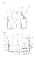
- FIG. 1 is a front view illustrating an inside of an air conditioner in accordance with a first preferred embodiment of the present invention
- FIG. 2 is a sectional view illustrating an inside of the control box in FIG. 1 ;
- FIG. 3 is a perspective view illustrating an inside of the control box in FIG. 1 ;
- FIG. 4 is an exploded perspective view illustrating the PCB in FIG. 2 , with a cooling module separated therefrom;
- FIG. 5 is a perspective view illustrating the PCB being cooled by the cooling module in FIG. 2 .
- FIG. 1 is a front view illustrating an inside of an air conditioner in accordance with a first preferred embodiment of the present invention
- FIG. 2 is a sectional view illustrating an inside of the control box in FIG. 1
- FIG. 3 is a perspective view illustrating an inside of the control box in FIG. 1
- FIG. 4 is an exploded perspective view illustrating the PCB in FIG. 2 , with a cooling module separated therefrom
- FIG. 5 is a perspective view illustrating the PCB being cooled by the cooling module in FIG. 2 .
- a PCB module 2 may be mounted to a control box 4 for controlling the air conditioner.
- the air conditioner may include a compressor 6 , an outdoor heat exchanger 8 , an expansion device, and an indoor heat exchanger, through which refrigerant circulates.
- the air conditioner may be a window type air conditioner which has the compressor, the outdoor heat exchanger, the expansion device, and the indoor heat exchanger mounted to one casing.
- the air conditioner may be a split type air conditioner including an outdoor unit 0 having the compressor 6 , an outdoor heat exchanger 8 , and an outdoor fan 10 mounted thereto, and an indoor unit having the indoor heat exchanger and the indoor fan mounted thereto.
- the PCB module 2 may control electric components of the compressor and the fan mounted to the window type air conditioner.
- the PCB module 2 and the control box 4 may be mounted to the indoor unit, and, in this case, the PCB module 2 may control electric components of the indoor fan and so on mounted to the indoor unit.
- the PCB module 2 and the control box 4 may be mounted to the outdoor unit 0 , and, in this case, the PCB module 2 may control the electric components of the compressor 6 , the outdoor fan 10 , and so on mounted to the outdoor unit.
- the air conditioner may have the PCB module 2 and the control box 4 mounted to the outdoor unit 0 , and the PCB module 2 mounted to the outdoor unit 0 may be air cooled with outdoor air. In this case, if the outdoor air is at a high temperature, the PCB module 2 can not dissipate heat therefrom efficiently due to the high temperature of the outdoor air. It is preferable for the air conditioner to dissipate heat from the PCB module 2 by using refrigerant rather than by using the outdoor air.
- the embodiment will be described taking an example in which the PCB module 2 and the control box 4 are mounted to the outdoor unit 0 of the split type air conditioner, the embodiment is not limited to a case in which the PCB module 2 and the control box 4 are mounted to the outdoor unit 0 , but it is apparent that the embodiment is applicable to cases in which the PCB module 2 and the control box 4 are mounted to the indoor unit of the window type air conditioner or the split type air conditioner.
- the PCB module 2 in the control box 4 may be cooled by the refrigerant or the air.
- the PCB module 2 may be arranged in a space formed in the control box 4 .
- the PCB module 2 may include a PCB (Printed Circuit Board) 22 and a plurality of electric components 24 and 26 mounted to the PCB 22 .
- the plurality of electric components 24 and 26 mounted to the PCB 22 may have heat generation rates different from one another depending on kinds thereof. Some 24 of the plurality of electric components 24 and 26 may construe a high heat generation part having a high heat generation rate, and other electric component 26 of the plurality of electric components 24 and 26 may construe a low heat generation part having a heat generation rate lower than the high heat generation part.
- the air conditioner may have the compressor 2 of an inverter compressor, and the plurality of electric components 24 and 26 may include a power supply unit for supplying power, an inverter for converting DC power to AC power, and other electric components having heat generation rates lower than the power supply unit or the inverter.
- the inverter or the power supply unit which has the high heat generation rate may be the first electric component 24 which is the high heat generation part, and other electric component having the heat generation rate lower than the power supply unit or the inverter may be a second electric component 26 which is the low heat generation part.
- the PCB module 2 may be arranged to form an air circulation passage P in the space S.
- the air circulation passage P may be a passage formed within the control box 4 not to be in communication with an outside of the control box 4 .
- the air circulation passage P may be an internal circulation passage formed to circulate the air within the control box 4 .
- the air in the space S may cool down the PCB module 2 while circulating the air circulation passage P.
- the air in the space S may be air within the control box which does not mix with the external air of the control box 4 .
- the air in the space S may be cooled by a cooling module 60 to be described later, and may circulate the air circulation passage P in a state cooled by the cooling module 60 .
- the control box 4 may have different components mounted thereto and protected thereby, and may have the space S formed therein.
- the space S may be an enclosure formed in the control box 4 .
- the control box 4 may include a box body 42 having an opened side, and a box cover 44 which closes the opened side of the box body 42 , to form the enclosure between the box body 42 and the box cover 44 which blocks in/out of the external air thereto/therefrom.
- the PCB module 2 in the control box 4 may be cooled, not only by refrigerant, but also by the air, wherein the air may be cooled down by the refrigerant, and flows within the control box 4 so that the air cooled down thus cools an inside of the control box 4 and the PCB module 2 while the air flows the inside of the control box 4 .
- the air conditioner makes the refrigerant to heat exchange with the PCB module 2 to dissipate heat from the PCB module 2 .
- the air conditioner may include a cooling module 60 for making the PCB module 2 to heat exchange with the refrigerant.
- the cooling module 60 may be connected to a circuit of a refrigerating cycle including the compressor 6 , the outdoor heat exchanger 8 , the expansion device and the indoor heat exchanger. Of a low temperature portion and a high temperature portion of a refrigerating cycle circuit, the cooling module 60 may be connected to the low temperature portion of the refrigerating cycle circuit such that the refrigerant passing through the low temperature portion passes through the cooling module 60 . A portion of the refrigerant passing through the low temperature portion of the refrigerating cycle circuit may flow to the cooling module 60 and passes through the cooling module 60 , to dissipate heat while the refrigerant passes through the cooling module 60 . The cooling module 60 may be arranged to be in contact with the PCB module 2 .
- the cooling module 60 may include a refrigerant pipe 62 through which the refrigerant passes, and refrigerant pipe 62 may have one end connected to the low temperature portion of the refrigerating cycle circuit.
- the refrigerant pipe 62 may have the other end connected to the low temperature portion of the refrigerating cycle circuit. If the PCB module 2 and the control box 4 are mounted to the outdoor unit 0 , the refrigerant pipe 62 may be connected to the refrigerant pipe between the outdoor heat exchanger 8 and the expansion device or to the refrigerant pipe between the expansion device and the indoor heat exchanger.
- the cooling module 60 may be arranged to heat exchange with a portion of the PCB module 2 .
- the cooling module 60 can make the high heat generation part of the PCB module 2 to heat exchange with the refrigerant.
- the PCB module 2 may have the high heat generation part heat exchanged with, and cooled by, the cooling module 60 and the low heat generation part heat exchanged with the air cooled by the cooling module 60 , and cooled by the air.
- the PCB module 2 may be cooled throughout the PCB module 2 uniformly owing to the refrigerant type cooling by the cooling module 60 and the air cooling type cooling by the air heat exchanged with the cooling module 60 .
- the cooling module 60 may include a heat transfer plate 64 for absorbing heat from the high heat generation part and transferring the heat absorbed thus to the refrigerant pipe 62 , and a heat absorbing plate 68 for absorbing heat from the air and transfer the heat absorbed thus from the air to the heat transfer plate 64 .
- the heat transfer plate 64 may include a first heat transfer plate 65 in contact with the high heat generation part and a second heat transfer plate 66 in contact with the heat absorbing plate 68 and arranged to share a contact area of the refrigerant pipe 62 with the first heat transfer plate 65 .
- the heat absorbing plate 68 may be positioned between the heat transfer plate 64 and the control box 4 .
- the heat absorbing plate 68 may be positioned in the air circulation passage P for heat exchange with the air in the air circulation passage P.
- the heat absorbing plate 68 may have at least one air passage 69 formed therein for pass through of the air in the air circulation passage P.
- the heat absorbing plate 68 may include a contact plate 70 in contact with the heat transfer plate 64 , and at least a fin 72 projected from the contact plate 70 .
- the heat absorbing plate 68 may have a plurality of the fins 72 arranged projected from the contact plate 70 , with the air passage 69 formed among the plurality of fins 72 .
- the air conditioner may further include a circulating fan 80 arranged in the air circulation passage P for making the air to flow such that, after the air is cooled by the cooling module 60 , the air is blown toward the low heat generation part of the PCB module 2 .
- the first electric component 24 may have a heat generation rate higher than the second electric component 26 .
- the first electric component 24 and the second electric component 26 may be arranged to be positioned on sides different from each other.
- the first electric component 24 may be arranged on one side 22 A of the PCB 22 and the second electric component 26 may be arranged on the other side 22 B of the PCB 22 .
- the PCB 22 may partition the space S into a first flow passage P 1 the first electric component 24 and the cooling module 60 are positioned therein, and a second flow passage P 2 the second electric component is positioned therein.
- the first flow passage P 1 may be positioned between one side 51 of an inside of the control box 4 and one side 22 A of the PCB 22 .
- the second flow passage P 2 may be positioned between the other side 52 of the inside of the control box 4 and the other side of the PCB 22 .
- One of the first flow passage P 1 and the second flow passage P 2 may have a flow passage cross section formed larger than the other one in an air flow direction.
- first communication passage P 3 for making the air in the first flow passage P 1 to flow to the second flow passage P 2
- second communication passage P 4 for making the air in the second flow passage P 2 to flow to the first flow passage P 1
- the PCB 22 may have one side edge 22 C spaced from the control box 4 to form the first communication passage P 3 and the other side edge 22 D spaced from the control box 4 to form the second communication passage P 4 .
- the PCB 22 may be arranged in the control box 4 , horizontally.
- the PCB 22 may have an underside spaced from a low plate of the control box 4 to form the first flow passage P 1 therebetween.
- the PCB 22 may have an upper side spaced from an upper plate of the control box 4 to form the second flow passage P 2 therebetween.
- the PCB 22 may have one side edge 22 C spaced from one side wall of the control box 4 to form the first communication passage P 3 therebetween.
- the PCB 22 may have the other side edge 22 D spaced from the other side wall of the control box 4 to form the second communication passage P 4 therebetween.
- the air conditioner may include a spacer 53 and 54 to place the PCB 22 thereon to form the first flow passage P 1 between the control box 4 and the PCB 22 .
- the spacer 53 and 54 may be arranged in the control box 4 .
- the spacer 53 and 54 may be arranged in the control box 4 for spacing the underside of the PCB 22 from the lower plate of the control box 4 , and, when the PCB 22 is placed on the spacer 53 and 54 , the PCB 22 may be spaced from the lower plate of the control box 4 to form the first flow passage P 1 between the PCB 22 placed on the spacer 53 and 54 and the lower plate of the control box 4 .
- the spacer 53 and 54 may be formed to have a height higher than a height of the cooling module 60 .
- the PCB 22 may be fastened to the control box 4 with fastening members such as screws.
- the spacer 53 and 54 may have fastening holes formed therein for fastening the fastening members thereto.
- the PCB 22 may have pass through holes formed at positions matched to the fastening holes in the spacer 53 and 54 for pass through of the fastening members.
- the PCB 22 may be fastened to the spacers 53 and 54 with the fastening members.
- the control box 4 may have a flow passage guide 56 formed thereon for guiding the air from the first flow passage P 1 to the circulating fan 80 .
- the control box 4 may have a refrigerant pipe pass through hole formed therein for pass through of the refrigerant pipe 62 .
- the cooling module 60 may make the first electric component 24 to heat exchange with the refrigerant.
- the cooling module 60 may have the heat transfer plate 64 in contact with the refrigerant pipe 62 and the first electric component 24 .
- the cooling module 60 may have the heat absorbing plate 68 in contact with the heat transfer plate 64 .
- the first heat transfer plate 65 may be in contact with the first electric component 24
- the second heat transfer plate 66 may be in contact with the first heat transfer plate 65 .
- the cooling module 60 may be a refrigerant cooling type cooling module in which the refrigerant pipe 62 and the heat transfer plate 64 cool the first electric component 24 , or an air cooling type cooling module in which the heat absorbing plate 68 cools the air positioned in the space S of the control box 4 .
- the air in the air circulation passage P may be cooled as the air heat exchanges with the heat absorbing plate 68 .
- the air may be cooled as the air heat exchanges with the heat absorbing plate 68 while the air passes through the first flow passage P 1 , and, thereafter, may cool the second electric component 26 by air cooling while the air passes through the second flow passage P 2 .
- the circulating fan 80 is arranged in the air circulation passage P for making the air to flow to be blown to the second electric component 26 of the plurality of electric components 24 and 26 after the air is cooled by the cooling module 60 .
- the circulating fan 80 may be positioned between the first electric component 24 and the second electric component 26 in an air flow direction.
- the circulating fan 80 may be mounted to be positioned between the PCB 22 and the control box 4 .
- the circulating fan 80 may be mounted to have a gap T to the control box 4 .
- the circulating fan 80 may be mounted in one of the first flow passage P 1 and the second flow passage P 2 .
- the circulating fan 80 may be positioned in a flow passage having a larger cross section of the first flow passage P 1 and the second flow passage P 2 .
- the circulating fan 80 may be mounted to be positioned in a flow passage having a larger cross section of the first flow passage P 1 and the second flow passage P 2 and in the first communication passage P 3 .
- the circulating fan 80 may draw the air from the first flow passage P 1 and blow the air to the second flow passage P 2 .
- the air circulation passage P may include a low temperature region flow passage and a high temperature region flow passage.
- the air circulation passage P may have the low temperature region flow passage between the heat absorbing plate 68 and the first communication passage P 3 and between the first communication passage P 3 and the circulating fan 80 in the air flow direction, and the low temperature region flow passage may be a flow passage through which the air C cooled by the heat absorbing plate 68 C passes.
- the air circulation passage P may have the high temperature region flow passage between the circulating fan 80 and the second communication passage P 4 and between the second communication passage P 4 and the heat absorbing plate 68 in the air flow direction, and the high temperature region flow passage may be a flow passage in which the air temperature rises gradually as the air passes therethrough.
- the compressor 6 When the air conditioner is in operation, the compressor 6 may be driven, and the outdoor fan 10 may be rotated.
- the refrigerant When the compressor 6 is driven, the refrigerant may be introduced to the compressor 6 after passing through the compressor 6 , the outdoor heat exchanger 8 , the expansion device and the indoor heat exchanger in succession, the outdoor heat exchanger 8 may heat exchange with the outdoor air flowed by the outdoor fan 10 , and the indoor heat exchanger may make the refrigerant to heat exchange with the room air to air condition the room.
- the air conditioner When the compressor 6 is driven, the air conditioner may have the refrigerant passing through the refrigerant pipe 62 . And, when the air conditioner is in operation, the circulating fan 80 may be driven. When the circulating fan 80 is driven, the control box 4 may have an air circulation formed therein.
- the refrigerant When the refrigerant is passing through the refrigerant pipe 62 , the heat may be absorbed from the heat transfer plate 64 to the refrigerant pipe 62 , and the heat may be absorbed from the first electric component 24 and the heat absorbing plate 68 to the heat transfer plate 64 . That is, when the refrigerant passes through the refrigerant pipe 62 , the first electric component 24 and the heat absorbing plate 68 may be cooled by the heat transfer plate 64 .
- the air may flow from the first flow passage P 1 to the cooling module 60 , particularly, the heat absorbing plate 68 to heat exchange with, and to be cooled by, the heat absorbing plate 68 .
- the air C cooled by the heat absorbing plate 68 may pass through the first communication passage P 3 thereafter, and may be drawn into the circulating fan 80 .
- the air drawn into the circulating fan 80 may be blown to the second flow passage P 2 .
- the air C blown to the second flow passage P 2 from the circulating fan 80 may cool the second electric component 26 and the second flow passage P 2 as the air passes through the second flow passage P 2 .
- the air absorbs heat while the air passes through the second flow passage P 2 , a temperature of the air may rise gradually, and the air may be introduced to the first flow passage P 1 passed through the second communication passage P 4 .
- the air H introduced to the first flow passage P 1 from the second communication passage P 4 may heat exchange with the heat absorbing plate 68 again in a state the air temperature is elevated and may be cooled by the heat absorbing plate 68 , again.
- the air in the air circulation passage P dissipates heat therefrom as the air passes through the first flow passage P 1 , absorbs the heat as the air passes through the second flow passage P 2 , to air cool the PCB module 2 and the inside of the control box 4 while repeating heat dissipation and heat absorption.
Landscapes
- Engineering & Computer Science (AREA)
- Mechanical Engineering (AREA)
- General Engineering & Computer Science (AREA)
- Physics & Mathematics (AREA)
- Thermal Sciences (AREA)
- Microelectronics & Electronic Packaging (AREA)
- Chemical & Material Sciences (AREA)
- Combustion & Propulsion (AREA)
- Life Sciences & Earth Sciences (AREA)
- Sustainable Development (AREA)
- Cooling Or The Like Of Electrical Apparatus (AREA)
Applications Claiming Priority (3)
| Application Number | Priority Date | Filing Date | Title |
|---|---|---|---|
| KR10-2013-0079183 | 2013-07-05 | ||
| KR1020130079183A KR102173373B1 (ko) | 2013-07-05 | 2013-07-05 | 공기조화기 |
| PCT/KR2014/005985 WO2015002493A1 (fr) | 2013-07-05 | 2014-07-04 | Appareil de conditionnement d'air |
Publications (2)
| Publication Number | Publication Date |
|---|---|
| US20160174411A1 US20160174411A1 (en) | 2016-06-16 |
| US10021809B2 true US10021809B2 (en) | 2018-07-10 |
Family
ID=52144005
Family Applications (1)
| Application Number | Title | Priority Date | Filing Date |
|---|---|---|---|
| US14/902,801 Active 2035-02-24 US10021809B2 (en) | 2013-07-05 | 2014-07-04 | Air conditioner |
Country Status (4)
| Country | Link |
|---|---|
| US (1) | US10021809B2 (fr) |
| EP (1) | EP3017255B1 (fr) |
| KR (1) | KR102173373B1 (fr) |
| WO (1) | WO2015002493A1 (fr) |
Cited By (1)
| Publication number | Priority date | Publication date | Assignee | Title |
|---|---|---|---|---|
| US20230168000A1 (en) * | 2020-08-26 | 2023-06-01 | Gd Midea Heating & Ventilating Equipment Co., Ltd. | Air conditioning apparatus and electric control box |
Families Citing this family (21)
| Publication number | Priority date | Publication date | Assignee | Title |
|---|---|---|---|---|
| KR102403512B1 (ko) * | 2015-04-30 | 2022-05-31 | 삼성전자주식회사 | 공기 조화기의 실외기, 이에 적용되는 컨트롤 장치 |
| CN108702849B (zh) * | 2016-03-04 | 2020-09-29 | 三菱电机株式会社 | 电气部件模块及空调机的室外机 |
| US11131466B2 (en) | 2017-02-10 | 2021-09-28 | Daikin Industries, Ltd. | Heat source unit and air conditioner having the heat source unit |
| EP3361173B1 (fr) * | 2017-02-10 | 2022-04-20 | Daikin Europe N.V. | Unité de source de chaleur et climatiseur comportant l'unité de source de chaleur |
| EP3361168B1 (fr) * | 2017-02-10 | 2022-04-20 | Daikin Europe N.V. | Unité de source de chaleur et climatiseur d'air comportant l'unité de source de chaleur |
| EP3361166A1 (fr) * | 2017-02-10 | 2018-08-15 | Daikin Europe N.V. | Unité source de chaleur et climatiseur équipé de ladite source de chaleur |
| US10925181B2 (en) * | 2017-03-21 | 2021-02-16 | Lg Innotek Co., Ltd. | Converter |
| JP6749293B2 (ja) * | 2017-08-09 | 2020-09-02 | ダイキン工業株式会社 | 冷凍装置の室外ユニット |
| JP6702346B2 (ja) * | 2018-02-26 | 2020-06-03 | ダイキン工業株式会社 | 冷凍装置の室外ユニット |
| JP7119458B2 (ja) * | 2018-03-19 | 2022-08-17 | 株式会社富士通ゼネラル | 空気調和機の室外機 |
| JP7159616B2 (ja) * | 2018-05-22 | 2022-10-25 | 株式会社富士通ゼネラル | 空気調和機の室外機 |
| CN112154294A (zh) * | 2018-05-31 | 2020-12-29 | 三菱电机株式会社 | 室外机以及制冷循环装置 |
| CN109357328A (zh) * | 2018-10-17 | 2019-02-19 | 宁波奥克斯电气股份有限公司 | 一种电控板散热控制装置及方法和空调器 |
| CN110567187A (zh) * | 2019-09-04 | 2019-12-13 | 珠海格力电器股份有限公司 | 电控箱、机组设备及电控箱散热控制方法 |
| JP7020464B2 (ja) * | 2019-09-26 | 2022-02-16 | 株式会社富士通ゼネラル | 電装品モジュール |
| CN110645640A (zh) * | 2019-10-25 | 2020-01-03 | 珠海格力电器股份有限公司 | 散热效率高的电器盒及室外机 |
| CN214676259U (zh) * | 2020-08-26 | 2021-11-09 | 广东美的暖通设备有限公司 | 空调装置以及电控盒 |
| WO2022042617A1 (fr) * | 2020-08-26 | 2022-03-03 | 广东美的暖通设备有限公司 | Appareil de climatisation et boîtier de commande électrique |
| JP2023047976A (ja) * | 2021-09-27 | 2023-04-06 | 株式会社デンソー | 制御装置 |
| CN114060967B (zh) * | 2021-11-29 | 2022-11-11 | 珠海格力电器股份有限公司 | 控制板温度的控制方法、系统、模组、空调和存储介质 |
| CN114576739B (zh) * | 2022-03-02 | 2023-09-01 | 宁波奥克斯电气股份有限公司 | 一种电控组件、空调室外机的电控盒组件和空调器 |
Citations (16)
| Publication number | Priority date | Publication date | Assignee | Title |
|---|---|---|---|---|
| JPH09138044A (ja) | 1995-11-17 | 1997-05-27 | Hitachi Ltd | 密閉筐体とその湿度制御法 |
| US6009717A (en) * | 1998-08-26 | 2000-01-04 | Carrier Corporation | Control box for a room air conditioner |
| KR20070052547A (ko) | 2005-11-17 | 2007-05-22 | 엘지전자 주식회사 | 공기조화기 |
| US20080000253A1 (en) * | 2006-07-03 | 2008-01-03 | Moon Shin Kim | Air conditioner |
| US20080302120A1 (en) * | 2005-01-27 | 2008-12-11 | Lg Electronics, Inc. | Indoor Unit of Air Conditioner |
| US20090081940A1 (en) * | 2007-09-21 | 2009-03-26 | Seok Hoon Jang | Outdoor unit of air conditioner |
| US20090137197A1 (en) | 2007-11-23 | 2009-05-28 | Seok Hoon Jang | Outdoor unit of air conditioner |
| US20090205352A1 (en) * | 2008-02-20 | 2009-08-20 | Samsung Electronics Co., Ltd. | Air conditioner and control box assembly |
| KR100954358B1 (ko) | 2006-01-25 | 2010-04-27 | 엘지전자 주식회사 | 공기조화기 실외기의 컨트롤박스 |
| JP2010266132A (ja) | 2009-05-15 | 2010-11-25 | Mitsubishi Heavy Ind Ltd | インバータ冷却装置およびインバータ冷却方法ならびに冷凍機 |
| JP2011220654A (ja) | 2010-04-14 | 2011-11-04 | Daikin Industries Ltd | 冷凍装置 |
| US20120105790A1 (en) * | 2008-12-18 | 2012-05-03 | Manufacturing Resources International, Inc. | System for cooling an electronic image assembly with manifolds and ambient gas |
| WO2012081056A1 (fr) | 2010-12-16 | 2012-06-21 | パナソニック株式会社 | Dispositif de refroidissement et climatiseur équipé de celui-ci |
| KR101172679B1 (ko) | 2004-07-14 | 2012-08-09 | 삼성전자주식회사 | 공기조화기의 실외기 |
| EP2522931A1 (fr) | 2010-01-05 | 2012-11-14 | Daikin Industries, Ltd. | Dispositif de réfrigération |
| US20150271949A1 (en) * | 2014-03-18 | 2015-09-24 | Lg Electronics Inc. | Outdoor unit of air conditioner |
Family Cites Families (3)
| Publication number | Priority date | Publication date | Assignee | Title |
|---|---|---|---|---|
| KR20070022948A (ko) | 2005-08-22 | 2007-02-28 | 엘지전자 주식회사 | 공기조화기 실외기의 방열구조 |
| JP2010014340A (ja) * | 2008-07-03 | 2010-01-21 | Daikin Ind Ltd | 冷凍装置 |
| JP2013015295A (ja) * | 2011-07-06 | 2013-01-24 | Panasonic Corp | 冷却装置およびそれを備えた空気調和機 |
-
2013
- 2013-07-05 KR KR1020130079183A patent/KR102173373B1/ko active IP Right Grant
-
2014
- 2014-07-04 US US14/902,801 patent/US10021809B2/en active Active
- 2014-07-04 EP EP14820006.6A patent/EP3017255B1/fr active Active
- 2014-07-04 WO PCT/KR2014/005985 patent/WO2015002493A1/fr active Application Filing
Patent Citations (17)
| Publication number | Priority date | Publication date | Assignee | Title |
|---|---|---|---|---|
| JPH09138044A (ja) | 1995-11-17 | 1997-05-27 | Hitachi Ltd | 密閉筐体とその湿度制御法 |
| US6009717A (en) * | 1998-08-26 | 2000-01-04 | Carrier Corporation | Control box for a room air conditioner |
| KR101172679B1 (ko) | 2004-07-14 | 2012-08-09 | 삼성전자주식회사 | 공기조화기의 실외기 |
| US20080302120A1 (en) * | 2005-01-27 | 2008-12-11 | Lg Electronics, Inc. | Indoor Unit of Air Conditioner |
| KR20070052547A (ko) | 2005-11-17 | 2007-05-22 | 엘지전자 주식회사 | 공기조화기 |
| KR100954358B1 (ko) | 2006-01-25 | 2010-04-27 | 엘지전자 주식회사 | 공기조화기 실외기의 컨트롤박스 |
| US20080000253A1 (en) * | 2006-07-03 | 2008-01-03 | Moon Shin Kim | Air conditioner |
| US20090081940A1 (en) * | 2007-09-21 | 2009-03-26 | Seok Hoon Jang | Outdoor unit of air conditioner |
| US20090137197A1 (en) | 2007-11-23 | 2009-05-28 | Seok Hoon Jang | Outdoor unit of air conditioner |
| US20090205352A1 (en) * | 2008-02-20 | 2009-08-20 | Samsung Electronics Co., Ltd. | Air conditioner and control box assembly |
| US8272229B2 (en) | 2008-02-20 | 2012-09-25 | Samsung Electronics Co., Ltd. | Air conditioner and control box assembly |
| US20120105790A1 (en) * | 2008-12-18 | 2012-05-03 | Manufacturing Resources International, Inc. | System for cooling an electronic image assembly with manifolds and ambient gas |
| JP2010266132A (ja) | 2009-05-15 | 2010-11-25 | Mitsubishi Heavy Ind Ltd | インバータ冷却装置およびインバータ冷却方法ならびに冷凍機 |
| EP2522931A1 (fr) | 2010-01-05 | 2012-11-14 | Daikin Industries, Ltd. | Dispositif de réfrigération |
| JP2011220654A (ja) | 2010-04-14 | 2011-11-04 | Daikin Industries Ltd | 冷凍装置 |
| WO2012081056A1 (fr) | 2010-12-16 | 2012-06-21 | パナソニック株式会社 | Dispositif de refroidissement et climatiseur équipé de celui-ci |
| US20150271949A1 (en) * | 2014-03-18 | 2015-09-24 | Lg Electronics Inc. | Outdoor unit of air conditioner |
Cited By (2)
| Publication number | Priority date | Publication date | Assignee | Title |
|---|---|---|---|---|
| US20230168000A1 (en) * | 2020-08-26 | 2023-06-01 | Gd Midea Heating & Ventilating Equipment Co., Ltd. | Air conditioning apparatus and electric control box |
| US11982459B2 (en) * | 2020-08-26 | 2024-05-14 | Gd Midea Heating & Ventilating Equipment Co., Ltd. | Air conditioning apparatus and electric control box |
Also Published As
| Publication number | Publication date |
|---|---|
| WO2015002493A1 (fr) | 2015-01-08 |
| US20160174411A1 (en) | 2016-06-16 |
| KR102173373B1 (ko) | 2020-11-03 |
| KR20150005338A (ko) | 2015-01-14 |
| EP3017255A1 (fr) | 2016-05-11 |
| EP3017255A4 (fr) | 2017-03-01 |
| EP3017255B1 (fr) | 2019-09-18 |
Similar Documents
| Publication | Publication Date | Title |
|---|---|---|
| US10021809B2 (en) | Air conditioner | |
| JP6285058B2 (ja) | サーバファーム冷却システムのための冷気列封入 | |
| US20200232658A1 (en) | Control box, and outdoor unit of air conditioner comprising same | |
| US10292313B2 (en) | Rackmount cooling system | |
| TWI624752B (zh) | 具有一冷排封裝結構以冷卻伺服器之資料中心及其方法 | |
| KR101298404B1 (ko) | 공기조화기의 실외기 | |
| SG175238A1 (en) | Cold row encapsulation for server farm cooling system | |
| US9353968B2 (en) | Heat source unit of refrigerating apparatus | |
| US20100314079A1 (en) | Heat dissipation device | |
| US20180010836A1 (en) | Heat transfer unit | |
| WO2022011620A1 (fr) | Module d'échange de chaleur et armoire | |
| KR102266357B1 (ko) | 이동형 공기조화기 | |
| JPH05118671A (ja) | 空気調和装置の電気品箱 | |
| CN112585409B (zh) | 室外机及空气调节机 | |
| KR102328715B1 (ko) | 공기조화장치의 실외기 | |
| KR20160080690A (ko) | 서버랙용 냉방장치 | |
| KR200432025Y1 (ko) | 통신기기용 공냉식 열 교환기 | |
| JPH0422185Y2 (fr) | ||
| KR20160080684A (ko) | 서버랙용 냉방장치 | |
| JP2004356274A (ja) | 盤用クーラ | |
| KR20160082296A (ko) | 서버랙용 냉방장치 | |
| JPH0336444A (ja) | 空気調和機の室外ユニット | |
| JP2010098217A (ja) | 熱交換装置およびそれを用いた発熱体収納装置 |
Legal Events
| Date | Code | Title | Description |
|---|---|---|---|
| AS | Assignment |
Owner name: LG ELECTRONICS INC., KOREA, REPUBLIC OF Free format text: ASSIGNMENT OF ASSIGNORS INTEREST;ASSIGNORS:LEE, YUNG KOO;HA, JONG CHUL;MOON, DONG SOO;AND OTHERS;SIGNING DATES FROM 20180524 TO 20180525;REEL/FRAME:046020/0485 |
|
| STCF | Information on status: patent grant |
Free format text: PATENTED CASE |
|
| MAFP | Maintenance fee payment |
Free format text: PAYMENT OF MAINTENANCE FEE, 4TH YEAR, LARGE ENTITY (ORIGINAL EVENT CODE: M1551); ENTITY STATUS OF PATENT OWNER: LARGE ENTITY Year of fee payment: 4 |