RU2420644C2 - Window or door with furniture - Google Patents
Window or door with furniture Download PDFInfo
- Publication number
- RU2420644C2 RU2420644C2 RU2008141275/12A RU2008141275A RU2420644C2 RU 2420644 C2 RU2420644 C2 RU 2420644C2 RU 2008141275/12 A RU2008141275/12 A RU 2008141275/12A RU 2008141275 A RU2008141275 A RU 2008141275A RU 2420644 C2 RU2420644 C2 RU 2420644C2
- Authority
- RU
- Russia
- Prior art keywords
- cable
- mounting plate
- grip
- window
- sash
- Prior art date
Links
- 238000010276 construction Methods 0.000 abstract description 2
- 238000006073 displacement reaction Methods 0.000 abstract 1
- 239000000126 substance Substances 0.000 abstract 1
- 238000009434 installation Methods 0.000 description 7
- 230000005540 biological transmission Effects 0.000 description 6
- 230000006835 compression Effects 0.000 description 3
- 238000007906 compression Methods 0.000 description 3
- 230000000903 blocking effect Effects 0.000 description 2
- 238000004891 communication Methods 0.000 description 2
- 238000005553 drilling Methods 0.000 description 2
- 239000004033 plastic Substances 0.000 description 2
- 230000001133 acceleration Effects 0.000 description 1
- 239000002131 composite material Substances 0.000 description 1
- 230000008878 coupling Effects 0.000 description 1
- 238000010168 coupling process Methods 0.000 description 1
- 238000005859 coupling reaction Methods 0.000 description 1
- 238000013461 design Methods 0.000 description 1
- 238000005516 engineering process Methods 0.000 description 1
- 239000000834 fixative Substances 0.000 description 1
- 210000002837 heart atrium Anatomy 0.000 description 1
- 238000012423 maintenance Methods 0.000 description 1
- 238000004519 manufacturing process Methods 0.000 description 1
- 238000005259 measurement Methods 0.000 description 1
- 239000002184 metal Substances 0.000 description 1
- 239000002991 molded plastic Substances 0.000 description 1
Images


Classifications
-
- E—FIXED CONSTRUCTIONS
- E05—LOCKS; KEYS; WINDOW OR DOOR FITTINGS; SAFES
- E05D—HINGES OR SUSPENSION DEVICES FOR DOORS, WINDOWS OR WINGS
- E05D15/00—Suspension arrangements for wings
- E05D15/56—Suspension arrangements for wings with successive different movements
- E05D15/565—Suspension arrangements for wings with successive different movements for raising wings before sliding
-
- E—FIXED CONSTRUCTIONS
- E05—LOCKS; KEYS; WINDOW OR DOOR FITTINGS; SAFES
- E05F—DEVICES FOR MOVING WINGS INTO OPEN OR CLOSED POSITION; CHECKS FOR WINGS; WING FITTINGS NOT OTHERWISE PROVIDED FOR, CONCERNED WITH THE FUNCTIONING OF THE WING
- E05F15/00—Power-operated mechanisms for wings
- E05F15/60—Power-operated mechanisms for wings using electrical actuators
- E05F15/603—Power-operated mechanisms for wings using electrical actuators using rotary electromotors
- E05F15/632—Power-operated mechanisms for wings using electrical actuators using rotary electromotors for horizontally-sliding wings
- E05F15/643—Power-operated mechanisms for wings using electrical actuators using rotary electromotors for horizontally-sliding wings operated by flexible elongated pulling elements, e.g. belts, chains or cables
- E05F15/646—Power-operated mechanisms for wings using electrical actuators using rotary electromotors for horizontally-sliding wings operated by flexible elongated pulling elements, e.g. belts, chains or cables allowing or involving a secondary movement of the wing, e.g. rotational or transversal
-
- E—FIXED CONSTRUCTIONS
- E05—LOCKS; KEYS; WINDOW OR DOOR FITTINGS; SAFES
- E05Y—INDEXING SCHEME ASSOCIATED WITH SUBCLASSES E05D AND E05F, RELATING TO CONSTRUCTION ELEMENTS, ELECTRIC CONTROL, POWER SUPPLY, POWER SIGNAL OR TRANSMISSION, USER INTERFACES, MOUNTING OR COUPLING, DETAILS, ACCESSORIES, AUXILIARY OPERATIONS NOT OTHERWISE PROVIDED FOR, APPLICATION THEREOF
- E05Y2800/00—Details, accessories and auxiliary operations not otherwise provided for
- E05Y2800/25—Emergency conditions
-
- E—FIXED CONSTRUCTIONS
- E05—LOCKS; KEYS; WINDOW OR DOOR FITTINGS; SAFES
- E05Y—INDEXING SCHEME ASSOCIATED WITH SUBCLASSES E05D AND E05F, RELATING TO CONSTRUCTION ELEMENTS, ELECTRIC CONTROL, POWER SUPPLY, POWER SIGNAL OR TRANSMISSION, USER INTERFACES, MOUNTING OR COUPLING, DETAILS, ACCESSORIES, AUXILIARY OPERATIONS NOT OTHERWISE PROVIDED FOR, APPLICATION THEREOF
- E05Y2900/00—Application of doors, windows, wings or fittings thereof
- E05Y2900/10—Application of doors, windows, wings or fittings thereof for buildings or parts thereof
- E05Y2900/13—Type of wing
- E05Y2900/132—Doors
-
- E—FIXED CONSTRUCTIONS
- E05—LOCKS; KEYS; WINDOW OR DOOR FITTINGS; SAFES
- E05Y—INDEXING SCHEME ASSOCIATED WITH SUBCLASSES E05D AND E05F, RELATING TO CONSTRUCTION ELEMENTS, ELECTRIC CONTROL, POWER SUPPLY, POWER SIGNAL OR TRANSMISSION, USER INTERFACES, MOUNTING OR COUPLING, DETAILS, ACCESSORIES, AUXILIARY OPERATIONS NOT OTHERWISE PROVIDED FOR, APPLICATION THEREOF
- E05Y2900/00—Application of doors, windows, wings or fittings thereof
- E05Y2900/10—Application of doors, windows, wings or fittings thereof for buildings or parts thereof
- E05Y2900/13—Type of wing
- E05Y2900/148—Windows
Landscapes
- Engineering & Computer Science (AREA)
- Mechanical Engineering (AREA)
- Power-Operated Mechanisms For Wings (AREA)
- Mechanical Coupling Of Light Guides (AREA)
- Massaging Devices (AREA)
- Infusion, Injection, And Reservoir Apparatuses (AREA)
- Operating, Guiding And Securing Of Roll- Type Closing Members (AREA)
- Securing Of Glass Panes Or The Like (AREA)
Abstract
Description
Изобретение относится к окну или двери с прибором согласно ограничительной части п. 1 формулы изобретения.The invention relates to a window or door with an appliance according to the preamble of claim 1.
Окно или дверь такого типа уже известны. В возрастающей степени предлагаются приборы для окон и дверей с моторными приводами. Это относится также к окнам и дверям - далее называются лишь только двери, которые должны перемещаться по вертикали или по горизонтали. Створка в случае перемещаемой вертикально створки поддерживается на боковых ходовых или направляющих рельсах. Соединение осуществляется с помощью направляющих элементов, которые установлены непосредственно или опосредованно на створке и принимаются в ходовых рельсах. В зависимости от веса створки может быть при этом предусмотрено, что вес створки воспринимается устройством снятия нагрузки, так чтобы обслуживающее лицо при ручном управлении должно было бы прилагать лишь небольшие усилия.A window or door of this type is already known. Increasingly, devices for windows and doors with motor drives are being offered. This also applies to windows and doors - hereinafter only doors are called that must move vertically or horizontally. The sash in the case of a vertically movable sash is supported on the side running or guide rails. The connection is made using guide elements that are installed directly or indirectly on the leaf and are received in the running rails. Depending on the weight of the sash, it can be provided that the weight of the sash is perceived by the load-relieving device, so that the operator would have to exert only small efforts with manual control.
В случае створки с перемещением по горизонтали на нижней или верхней горизонтальной кромке рамы предусмотрен ходовой рельс, который воспринимает силу веса посредством ходовой каретки. Ходовая каретка передает силу веса створки на раму, в то время как направляющий рельс стабилизирует створку.In the case of a leaf with horizontal movement, a running rail is provided on the lower or upper horizontal edge of the frame, which receives the force of weight by means of the running carriage. The carriage transfers the weight of the leaf to the frame, while the guide rail stabilizes the leaf.
Если створка приводится в движение с помощью двигателя, то привод воздействует на створку посредством захвата. Захват является отдельной конструктивной деталью, которая предусмотрена лишь при створке с моторным приводом, так что направляющие элементы, ходовая каретка и ходовые рельсы при ручном и моторном обслуживании, в сущности, могут оставаться неизменными. Моторный привод с помощью, например, направляемой на направляющем рельсе ленты посредством захвата воздействует на разблокированную для открытия створку и тянет ее.If the sash is driven by a motor, the drive acts on the sash by means of a grip. The gripper is a separate structural part, which is provided only for a leaf with a motor drive, so that the guide elements, running carriage and running rails during manual and motor maintenance, in essence, can remain unchanged. A motor drive, for example, by means of a belt guided on a guide rail by means of a gripper, acts on the sash that is unlocked for opening and pulls it.
В случае створки, которая опущена в положение закрытия, следует сначала привести в действие интегрированное обычно в ходовую каретку подъемное устройство. Для этого шатунный прибор створки, который находится в приводной связи с подъемным устройством, снабжен вторым приводом в форме двигателя. Он воздействует на шатунный прибор и может перемещаться вместе со створкой.In the case of a sash which is lowered to the closing position, the lifting device, usually integrated in the travel carriage, must first be activated. For this, the shutter connecting rod device, which is in drive communication with the lifting device, is equipped with a second drive in the form of an engine. It acts on the connecting rod device and can move with the sash.
Из EP 1 507 059 A2 известен прибор, в случае которого пытаются отказаться от применения второго двигателя. Благодаря этому, однако, также больше невозможно перемещать створку независимо от двигателя, например, чтобы ее привести в опущенное положение, если створка открыта.A device is known from EP 1 507 059 A2, in which case they are trying to refuse to use a second engine. Due to this, however, it is also no longer possible to move the sash independently of the engine, for example to bring it into a lowered position if the sash is open.
В известном приборе согласно инструкции по применению Atrium HS 300E, Hautau, предусмотрено, что на шатунный прибор воздействует электрический привод. Этот привод установлен в проеме створки и снабжается энергией посредством кабеля, который идет от рамы через захват на створку. Кабель проходит к захвату в открытом пазу и присоединен к приводу с помощью штекера.In a known device according to the instructions for use of the Atrium HS 300E, Hautau, it is provided that an electric drive acts on the connecting rod device. This drive is installed in the opening of the sash and is supplied with energy through a cable that goes from the frame through the grip to the sash. The cable passes to the grip in an open groove and is connected to the drive with a plug.
Захват вдвигается в расположенный на стороне привода зажимной элемент, из которого выходит кабель со штекером. Кабель без защиты уложен в паз захвата. Затем между створкой и захватом должно замыкаться штекерное соединение, хотя захват еще не окончательно позиционирован. Из-за этого возникает лишний участок кабеля, укладка которого в створке затруднительна.The grip slides into the clamping element located on the drive side, from which the cable with the plug exits. The cable without protection is laid in the grip groove. Then, between the leaf and the grip, the plug connection should be closed, although the grip is not yet fully positioned. Because of this, an extra section of cable arises, which is difficult to lay in the casement.
Поэтому в основе изобретения лежит задача создать конструкцию, которая позволяет осуществлять простой монтаж кабеля и захвата. В частности, улучшается прокладка кабеля к створке и в створке.Therefore, the basis of the invention is the task of creating a design that allows for simple installation of the cable and capture. In particular, cable routing to the sash and to the sash is improved.
Решение этой задачи осуществляется с помощью средств, приведенных в п.1 формулы изобретения.The solution to this problem is carried out using the means given in claim 1 of the claims.
С помощью признаков п.1 формулы изобретения к тому же достигается надежное, способное выдерживать нагрузку присоединение захвата к створке. Монтаж кабеля и захвата упрощается, и кабель надежно размещен.Using the features of claim 1, a reliable, load-bearing attachment of the gripper to the sash is also achieved. Cable and grip installation is simplified and the cable is securely placed.
Благодаря тому что монтажная плита имеет одну или несколько выступающих цапф, которой или которым соответствуют отверстия в створке, можно, во-первых, повысить несущую способность монтажной плиты, а во-вторых, простым способом определить размещение монтажной плиты на створке. Опорные цапфы вводятся в отверстия, которые, например, выполнены на створке с помощью сверлильного шаблона. Таким образом, быстро и надежно устанавливается положение относительно створки.Due to the fact that the mounting plate has one or more protruding pins, to which or to which the holes in the casement correspond, it is possible, firstly, to increase the load-bearing capacity of the mounting plate, and secondly, in a simple way to determine the placement of the mounting plate on the casement. The support trunnions are inserted into the holes, which, for example, are made on the leaf using a drilling template. Thus, the position relative to the sash is quickly and reliably established.
Соединение захвата и монтажной плиты можно улучшить, соединяя захват и монтажную плиту с помощью геометрического замыкания и заключая монтажную плиту в выемку захвата.The connection of the gripper and the mounting plate can be improved by connecting the gripper and the mounting plate with a geometric closure and enclosing the mounting plate in the recess of the gripper.
Простой вариант выполнения может при этом предусмотреть, что захват имеет форму S или Z, причем одно концевое плечо имеет выемку.A simple embodiment may provide that the gripper has the shape of S or Z, with one end arm having a recess.
Целесообразно также, если захват и монтажная плита совместно способствуют снятию тяговой нагрузки и зажимают кабель между собой.It is also advisable if the grip and mounting plate together contribute to the removal of traction and clamp the cable together.
Чтобы достичь связи с приводом, далее предусмотрено, что концевое плечо образует зажимной элемент. Соединение с приводом может достигаться с помощью этого, интегрированного в захвате, зажимного элемента.In order to achieve communication with the drive, it is further provided that the end arm forms a clamping member. Connection to the drive can be achieved with this integrated gripping element.
Для прикрепления можно также предусмотреть, чтобы в монтажной плите и захвате были предусмотрены проходящие коаксиально отверстия для крепежных винтов. Обе части благодаря этому можно устанавливать на створке с помощью совместных крепежных средств в один рабочий ход.For attachment, it can also be provided that coaxially extending holes for fixing screws are provided in the mounting plate and grip. Due to this, both parts can be installed on the sash using joint fastening means in one working stroke.
Монтаж можно еще больше облегчить благодаря тому, что на монтажной плите предусмотрено средство для временного фиксирования кабеля.Installation can be further facilitated by the fact that a means for temporarily securing the cable is provided on the mounting plate.
Чтобы проложить кабель на стороне сгиба створки, можно в створке выполнить выемку с открытыми краями, которая, по меньшей мере, частично снова замыкается и прикрывается монтажной плитой. Предпочтительно, однако, предусмотрено, что кабель через отверстие в створке проложен на стороне сгиба и при этом проходит через отверстие или выемку в монтажной плите. Отверстие для кабеля в створке может изготавливаться вместе с отверстиями опорной цапфы.To lay the cable on the fold side of the sash, you can make a recess in the sash with open edges, which at least partially closes again and is covered by a mounting plate. Preferably, however, it is provided that the cable through the hole in the casement is laid on the bend side and at the same time passes through the hole or recess in the mounting plate. The cable hole in the casement can be made together with the holes of the support pin.
В чертежах представлены дальнейшие предпочтительные варианты выполнения. Показывают:The drawings show further preferred embodiments. Show:
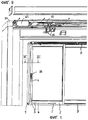
Фиг.1 - вид выреза двери, а также расположение прибора,Figure 1 - view of the cutout of the door, as well as the location of the device,
Фиг.2 - вид в перспективе деталей, относящихся к прибору,Figure 2 is a perspective view of parts related to the device,
Фиг.3 - каретку подъемно-передвижного прибора,Figure 3 - carriage of a lifting and movable device,
Фиг.4 - детализированное изображение первого моторного привода на створке,Figure 4 is a detailed image of the first motor drive on the sash,
Фиг.5 - схематическое изображение моторного привода согласно фиг.4,5 is a schematic illustration of a motor drive according to figure 4,
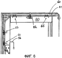
Фиг.6 - вырез створки с проложенным в ней кабелем,6 is a cutout of the sash with the cable laid in it,
Фиг.7 - вырез из поперечного сечения вдоль линии VII-VII из фиг.17 is a cutout from a cross section along the line VII-VII of figure 1
Фиг.8 - пространственное изображение направляющего элемента для направления кабеля на створке,Fig - spatial image of the guide element for guiding the cable on the sash,
Фиг.9 - вырез из верхнего участка рамы со вторым моторным приводом,Fig.9 is a cutout from the upper portion of the frame with a second motor drive,
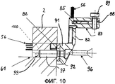
Фиг.10 - пространственное изображение захвата и монтажной плиты иFigure 10 - spatial image of the capture and mounting plate and
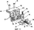
Фиг.11 - поперечное сечение створки с захватом и монтажной плитой.11 is a cross section of a sash with a grip and a mounting plate.
На фиг. 1 показаны жестко установленная рама 1 и поднимаемая и перемещаемая створка 2. Створка 2 снабжена прибором 3, который включает в себя две ходовые каретки 4 и 5, шатунный механизм 6, нижний ходовой рельс 7 и верхний направляющий рельс 8.In FIG. 1 shows a rigidly mounted frame 1 and a raised and
На фиг. 2 представлены существенные составляющие части прибора 3 без створки 2, вид в перспективе.In FIG. 2 shows the essential components of the
Каретки 4,5 связаны друг с другом с помощью соединительного стержня 9. На передней каретке 4 при этом расположен угловой механизм 10 для отклонения произведенного шатунным механизмом 6 движения не показанного здесь толкающего элемента или шатуна перемещающего механизма. На раме 1 предусмотрены блокирующие элементы 11,12. Для приведения в действие шатунного механизма 6 предусмотрен моторный привод, который на фиг. 1 обозначен позицией 39.The
Передняя каретка 4, которая, по существу, выполнена так же, как и задняя каретка 5, изображена детализированно на фиг.3. На роликовой опоре 13 расположены с возможностью вращения на расстоянии друг от друга ходовые ролики, которые накладываются на обозначенный штрихпунктирной линией ходовой рельс 7 на основании или на нижней поперечине составной рамы. Передний в направлении 16 перемещения - здесь не показанной - створки 2 конец роликовой опоры 13 связан с возможностью поворота с соединительной серьгой 17, которая со своей стороны закреплена с возможностью поворота на конусном уголке 18. Последний может поворачиваться на расположенном на навинченном уголке 19 опорном болте 20. Его другой конец посредством другого поворотного шарнира 21 связан с соединительной серьгой 22. Навинченный уголок 19 прикреплен к створке 2 с помощью непоказанных винтов. Представленный на фиг.2 шатунный механизм 6 имеет U-образный направляющий рельс для установленного с возможностью движения вверх и вниз шатуна. С помощью сцепной муфты 24 соединяются шатун и соединительная серьга 22 углового механизма 10.The
Таким образом, движение вверх и вниз шатуна в направлении двойной стрелки 23 (фиг. 2) вызывает перемещение и одновременный поворот соединительной серьги 22. В свою очередь она вызывает вращение конусного угла 18 вокруг его опорного болта 20 и тем самым перемещение и одновременный поворот соединительной серьги 17 вокруг ее оси 29 опоры на роликовой опоре 9. Движение вверх шатуна согласно этому приводит к перемещению роликовой опоры 13 относительно привинченного уголка 19 и, таким образом, также относительно створки 2 в направлении перемещения стрелки 16.Thus, the up and down movement of the connecting rod in the direction of the double arrow 23 (Fig. 2) causes the connecting
В роликовой опоре 13 в качестве подъемного элемента 30 расположен подъемный блок. Он входит в имеющий форму дуги направляющий шлиц 31 жестко связанного с навинченным уголком 19 направляющего корпуса 32. Нижний расположенный на фиг.3 слева конец 33 этого направляющего шлица 31 проходит при этом почти горизонтально. Кроме того, он может использоваться в качестве упора для подъемного элемента 30. Если теперь шатун движется вверх, то это способствует перемещению подъемного элемента 30 справа налево. За счет соединения с направляющим шлицем 31 это боковое перемещение подъемного блока (подъемного элемента 30) вызывает поднимание направляющего корпуса 32 и, тем самым, створки 2. Это движение подъема в течение всего времени движения подъема шатуна проходит постоянно вверх. Обратное движение осуществляется лишь при движении шатуна вниз. В поднятом положении створка 2 может перемещаться относительно рамы 1. В опущенном положении створка 2 закрепляется на раме 1 с помощью блокирующих элементов 11, 12.In the
На фиг. 4 и 5 показан в деталях моторный привод 39. Из фиг.4 становится при этом ясно, что моторный привод 39 состоит из двигателя 40 и связанного с ним передаточного механизма 41, которые смонтированы на одной крепежной плите 42. Соединение с шатунным механизмом 6 осуществляется с помощью четырехгранного вала 43 (фиг.5). Моторный привод 39 может благодаря этому использоваться вместо предусматриваемого в противном случае, управляемого вручную, ручного рычага. Шатунный механизм 6 и прибор 3 сами по себе остаются идентичными.In FIG. 4 and 5 shows the
Из схематического изображения на фиг. 5 явствует конструкция моторного привода 39. Двигатель 40 выполнен в виде привода низкого напряжения с высокой скоростью вращения, который с различными передаточными ступенями 44a, 44b, 44c соединен с выходным валом 45. Выходной вал 45 конструктивно рассчитан в сочетании с четырехгранным валом 43 и имеет с обратной стороны выступ 46 вала с гнездом 47 для инструмента.From the schematic representation in FIG. 5, the construction of the
Далее, вал 48 передаточной ступени 44b расположен в корпусе 49 передаточного механизма с возможностью перемещения в осевом направлении и на одном конце выступает за корпус 49 передаточного механизма. Вал 48 с помощью аккумулятора энергии в форме пружины 50 сжатия нагружается усилием в направлении лицевой поверхности. Если выступ 51 вала 48 перемещается в направлении стрелки 52 - против направления действия пружины 50 сжатия, то передаточные ступени 44a и 44b отключаются. Благодаря этому при введенном инструменте 53 можно ввести в действие функцию аварийного обслуживания, так как требуемое усилие ручного приведения в действие можно существенно снизить вследствие отпадения передаточных ступеней 44a и 44b и, тем самым, двигателя 40.Further, the shaft 48 of the transmission stage 44b is disposed axially movable in the
Инструмент 53 в состоянии пользования дверью размещен в корпусе 54,55, который прикрывает моторный привод 39. При отказе моторного привода 39, например, при отсутствии тока или т.п. дверь можно открыть после удаления корпуса 54,55 и нажатия на выступ 51 вала с помощью введенного инструмента 53.The
Из фиг. 4, далее, становится ясным, что снабжение моторного привода 39 энергией осуществляется посредством кабеля 56, который - как вытекает из фиг. 6 - проложен в пазу 60 прибора створки 2. Паз 60 прибора выполнен в виде открытого паза в поверхности 61 фальца створки 2 и имеет прямоугольное поперечное сечение. В него входит шатунный механизм, как это становится ясным в сочетании с фиг. 7 на основе шатунного механизма 6. Шатунный механизм 6 имеет, по существу, U-образный рельс 62, который завершается поверхностью 61 фальца. В рельсе 62 направляется шатун 63 с возможностью перемещения в поднутрении 64.From FIG. 4, it becomes clear that the power supply of the
В основании 65 паза 60 прибора расположен направляющий элемент 66, который имеет отверстие 67 для прохождения крепежного винта 68. Крепежный винт 68 наряду с отверстием 67 проходит также через рельс 62 в предусмотренном для этого отверстии 69. Направляющий элемент имеет, по существу, W-образное поперечное сечение, которое образовано выступающей в направлении основания 65 паза центральной перемычкой 70 и расположенными с отступлением назад боковыми перемычками 71, 72, а также направленными от них в направлении основания 65 паза краевыми рейками 73,74. Между краевыми рейками 73,74 возникают благодаря этому проходящие вдоль продольной центральной оси и центральной перемычки 70 U-образные приемные устройства 75,76, которые служат для приема кабеля 56. Кабель 56 благодаря этому направляется по обе стороны центральной перемычки 70, в которой расположено отверстие 67.At the
Прокладка кабеля 56 на створке 2 существенно упрощается благодаря тому, что кабель 56 можно расположить перед закреплением прибора 3. Кабель 56 с помощью направляющего элемента 66 направляется вокруг области, в которой могли бы установиться или устанавливаются крепежные винты 68. Таким образом, исключается повреждение кабеля 56, когда вводится крепежный винт 68.Laying the
Монтаж направляющего элемента 66 можно при этом осуществить различными путями.The installation of the
Во-первых, можно предусмотреть, чтобы направляющий элемент 66 был предусмотрен на створке 2, прежде чем монтируется прибор 3. Это предполагает знание точного положения крепежного винта 68, чтобы он мог пройти через отверстие 67. Положение отверстий 69 в рельсе 62, в общем, известно или может быть определено с помощью измерительной техники. Через направляющие элементы 66 затем в основании 65 паза пропускают предусмотренные для этого и здесь не показанные крепежные винты, которые проходят через установленные в продольном направлении - вдоль продольной центральной оси 77 центральной перемычки 70 - навинченные накладки 79. Навинченные накладки 79 выполнены в виде удлинений в продольном направлении центральной перемычки 70 и выступают над гнездами 75, 76, так что при креплении с помощью проходящих через навинченные накладки крепежных винтов кабель 56 остается видимым и не попадает ошибочно под центральную перемычку 70 и не повреждается за счет этого.First, it can be envisaged that the
Можно, однако, в качестве альтернативы этому предусмотреть, чтобы направляющие элементы 66 закреплялись на рельсах 62, и рельсы 62 использовались в качестве калибра, чтобы определить положение крепежных винтов 68. Краевые рейки 73,74 имеют для этого средства 77 фиксирования, которые взаимодействуют с рельсом 62 прибора - здесь шатунного механизма 6. Пружинящие краевые планки 73,74 имеют для этого выступающие наружу продольные утолщения (фиг.8), которые входят в продольные пазы рельсов 62. Благодаря этому направляющие элементы 66 при еще не смонтированных рельсах 62 можно прикреплять к ним с возможностью разъема и затем предварительно просверлить отверстия вместе с рельсом 62. В заключение направляющие элементы 66 отделяются от рельсов 62 и закрепляются в пазу 60 прибора вместе с кабелем 56. Рельс 62, соответственно, шатунный механизм 6 во втором рабочем ходе вводятся в паз 60 прибора и временно фиксируются с помощью направляющего элемента 66, пока не будет введен крепежный винт 68. В частности, преимущество временного фиксирования получается также в первом случае монтажа.You can, however, as an alternative to this, provide that the
Для того чтобы можно было сбалансировать незначительные неточности при монтаже предусмотрено, что отверстие 67 выполнено в виде продольного отверстия, как показано на фиг.8. Благодаря этому могут быть выровнены незначительные отклонения в положении направляющих элементов 66 относительно рельса 62.In order to be able to balance minor inaccuracies during installation, it is provided that the
Чтобы закрепить кабель 56 в гнездах 75,76, предусмотрено, что центральная перемычка 70 снабжена выступающими в направлении краевых реек 73,74 фиксирующими крюками 78, которые захватывают кабель или, по меньшей мере, часть его. Благодаря этому исключается выведение кабеля 56 из гнезд 75,76 при монтаже. Можно также, в отклонении от изображения на фиг. 7 и 8, предусмотреть, что гнезда 75,76 имеют различную форму и размеры, удовлетворяющие требованиям различных кабелей 56, например, для передачи сигналов, с одной стороны, или кабелей подачи энергии, с другой стороны. Также применение направляющих элементов 66 не ограничивается приборами указанного вначале типа. Направляющие элементы 66 могут использоваться также в приборах, которые предусматривают другие типы отверстий.In order to secure the
Целесообразно изготавливать направляющий элемент 66 в виде формованной детали из пластмассы, так как, таким образом, можно совмещать требуемые упругие свойства с экономичным изготовлением. Направляющий элемент в показанном примере выполнен симметрично относительно продольной оси и центральной поперечной оси.It is advisable to produce the
Из фиг.6 видно, что кабель 56 направляется по верхним горизонтальным поперечинам 80 створки и здесь - в отсутствии прибора 3 с рельсом 62 - также скреплен с направляющими элементами 66. Излишний кабель 56 при этом закреплен в петле 81 в не используемом иначе пазу 60 прибора и направлен к захвату 82, который приблизительно посередине прикреплен к поперечине 80 створки.Figure 6 shows that the
Захват 82, как видно из фиг.9, служит для соединения створки 2 с моторным приводом 83, который установлен на верхнем горизонтальном косяке 84 рамы. Привод 83 здесь также приводится в действие с помощью электрической энергии и имеет приводной ремень 85, который может прикрепляться к захвату 82.The
Захват 82, как видно из фиг. 10 и 11, посредством монтажной плиты 86 прикреплен к створке 2. Захват 82 имеет S- или Z-образный контур. На концевом плече 87 предусмотрена выемка 88 для приводного ремня 85, который можно жестко зажать в выполненной в форме шлица выемке 88 с помощью винтов 89, 90, причем концевое плечо 87 в целом образует зажимной элемент.
На концевом плече 91 выполнена выемка 92, которая по размерам соответствует монтажной плите 86, так чтобы она полностью прикрывалась в смонтированном состоянии захвата 82. Для этого выемка 92 образована перемычками 93, которые по типу краевых реек выступают на концевом плече 91. Захват 82 и монтажная плита 86 связаны с помощью геометрического замыкания, которое дополнительно подстраховано благодаря тому, что в монтажной плите 86 и захвате предусмотрены проходящие коаксиально отверстия 94,95 для крепежных винтов 96. С их помощью захват 82 и монтажная плита 86 совместно закреплены на створке 2.A
Монтажная плита 86 имеет две выступающие опорные цапфы 97,98, которые соответствуют отверстиям 99 в створке 2. Через опорные цапфы 97,98 могут особенно хорошо передаваться возникающие поперечные усилия. Если створка 2 перемещается с помощью приводного ремня 85, то на захвате 82, наряду с усилиями для перемещения створки 2, возникают также моменты, которые обоснованы расстоянием концевого плеча 87 до точки крепления на створке 2. Обе составляющие сил должны передаваться на створку 2 и зависят от веса створки 2 и ускорения, с которым моторный привод 83 пытается привести в действие створку 2. Наряду с увеличением несущей способности монтажной плиты 86 и закрепленного на ней с геометрическим замыканием захвата 82, во-вторых, простым образом улучшается размещение монтажной плиты 86 на створке 2. Опорные цапфы 97, 98 вводятся в отверстия 99, которые выполнены на створке 2 перед монтажом, например, с помощью сверлильных шаблонов. Таким образом, быстро и надежно фиксируется положение захвата 82 относительно створки 2, и с помощью двух опорных цапф 97, 98 также гарантируется, что направление приемной выемки 88 проходит точно параллельно кромке створки. Благодаря этому исключается нежелательное перекручивание приводного ремня 85.The mounting
При выполнении отверстий 99 можно предусмотреть к тому же другое, обозначенное на фиг.10 позицией 100, отверстие, которое является пропускным отверстием для кабеля 56. Через отверстие 100 кабель 56 прокладывается на стороне фальца - здесь поверхность 61 фальца. Для этого кабель 56 проходит через отверстие 101 (фиг.11) в монтажной плите 86.When making
Монтажная плита 86 имеет проходящий Г-образно направляющий уголок 102, который служит для приема и направления кабеля 56. Направляющий уголок 102 выполнен в виде изогнутого U-образного в сечении канала, который открыт в направлении захвата 82, так что кабель 56 с самого начала после прохождения через отверстие 100 может выводиться перпендикулярно без мест перелома. В направляющем уголке 102 при этом установлены средства в форме фиксирующих крючков или связывающих средств для кабеля или т.п., которые позволяют временное фиксирование кабеля 56 в канале.The mounting
В захвате 82 предусмотрен паз 103, который по размерам соответствует направляющему уголку 102. Чтобы снять тяговую нагрузку и зажать кабель 56 между собой, на захвате 82 в направлении направляющего уголка 102 предусмотрены выступающие зажимные средства, которые сужают канал до необходимого для кабеля 56 размера.A
Монтажная плита 86 может быть спроектирована в виде пластмассовой формованной детали. Может быть целесообразным, однако, в частности, для повышения несущей способности выполнить монтажную плиту 86 в виде фасонной детали из металла и направляющий уголок 102 разместить на этой фасонной детали в качестве фиксирующего элемента. Опорные цапфы 97,98 в этом варианте выполнения следует приварить к монтажной плите 86 или, по меньшей мере, закрепить с помощью пластической деформации.The mounting
Перечень обозначенийNotation list
Claims (9)
Applications Claiming Priority (2)
| Application Number | Priority Date | Filing Date | Title |
|---|---|---|---|
| DE102006013086.3 | 2006-03-20 | ||
| DE102006013086A DE102006013086A1 (en) | 2006-03-20 | 2006-03-20 | Fitting for a window or a door |
Publications (2)
| Publication Number | Publication Date |
|---|---|
| RU2008141275A RU2008141275A (en) | 2010-04-27 |
| RU2420644C2 true RU2420644C2 (en) | 2011-06-10 |
Family
ID=37964646
Family Applications (1)
| Application Number | Title | Priority Date | Filing Date |
|---|---|---|---|
| RU2008141275/12A RU2420644C2 (en) | 2006-03-20 | 2007-01-22 | Window or door with furniture |
Country Status (7)
| Country | Link |
|---|---|
| EP (1) | EP1999331B2 (en) |
| AT (1) | ATE461344T1 (en) |
| DE (2) | DE102006013086A1 (en) |
| ES (1) | ES2339716T5 (en) |
| PL (1) | PL1999331T5 (en) |
| RU (1) | RU2420644C2 (en) |
| WO (2) | WO2007107390A1 (en) |
Families Citing this family (5)
| Publication number | Priority date | Publication date | Assignee | Title |
|---|---|---|---|---|
| ITMI20070820A1 (en) † | 2007-02-12 | 2008-08-13 | Francesco Battistella | WINDOW. |
| DE202007011078U1 (en) | 2007-08-08 | 2007-10-11 | Siegenia-Aubi Kg | Motor drive for a wing of a window or door |
| IT1403672B1 (en) * | 2011-02-02 | 2013-10-31 | Amer Spa | MOTORIZED WINDOW |
| EP2933408B1 (en) | 2014-03-17 | 2017-07-19 | Gretsch-Unitas GmbH Baubeschläge | Lifting/sliding door assembly |
| KR101935982B1 (en) * | 2015-09-02 | 2019-04-03 | (주)엘지하우시스 | Apparatus for converting auto-manual modes of lift sliding window and smart window using the same |
Family Cites Families (9)
| Publication number | Priority date | Publication date | Assignee | Title |
|---|---|---|---|---|
| GB208808A (en) * | 1922-09-30 | 1923-12-31 | Alan Kirk | Improvements in or relating to saddle and like clamps, for cab tyre, metal and like sheathed electric conductors |
| GB889579A (en) * | 1959-04-15 | 1962-02-21 | United Carr Fastener Corp | Improvements in and relating to fastening devices |
| GB1028026A (en) * | 1964-04-29 | 1966-05-04 | Raymond A | An improved cable holding device |
| GB2174451A (en) * | 1985-05-02 | 1986-11-05 | Ega Ltd | A clip for tubing and a cover associated therewith |
| JP2004142704A (en) * | 2002-10-28 | 2004-05-20 | Sumitomo Wiring Syst Ltd | Cable wiring support part structure for slide door |
| JP2005057968A (en) * | 2003-08-07 | 2005-03-03 | Yazaki Corp | Protector for securing harness |
| DE20312683U1 (en) * | 2003-08-11 | 2003-11-06 | Gretsch-Unitas GmbH Baubeschläge, 71254 Ditzingen | Lift-slide fittings |
| DE202005000165U1 (en) * | 2005-01-07 | 2006-02-16 | ATS Automatik-Tür-Systeme GmbH | Separating wall used as a glass panel comprises wall elements each having a control unit which can be programmed |
| DE102005002179A1 (en) † | 2005-01-17 | 2006-08-03 | W. Hautau Gmbh | Wing arrangement with moving wing and fixed wing |
-
2006
- 2006-03-20 DE DE102006013086A patent/DE102006013086A1/en not_active Withdrawn
-
2007
- 2007-01-22 RU RU2008141275/12A patent/RU2420644C2/en active
- 2007-01-22 ES ES07704058T patent/ES2339716T5/en active Active
- 2007-01-22 WO PCT/EP2007/050591 patent/WO2007107390A1/en active Application Filing
- 2007-01-22 WO PCT/EP2007/050590 patent/WO2007107389A1/en active Application Filing
- 2007-01-22 DE DE502007003149T patent/DE502007003149D1/en active Active
- 2007-01-22 AT AT07704058T patent/ATE461344T1/en active
- 2007-01-22 EP EP07704058.2A patent/EP1999331B2/en not_active Not-in-force
- 2007-01-22 PL PL07704058T patent/PL1999331T5/en unknown
Also Published As
| Publication number | Publication date |
|---|---|
| ES2339716T5 (en) | 2019-10-09 |
| WO2007107389A1 (en) | 2007-09-27 |
| DE102006013086A1 (en) | 2007-09-27 |
| EP1999331B2 (en) | 2019-04-03 |
| PL1999331T5 (en) | 2019-12-31 |
| EP1999331A1 (en) | 2008-12-10 |
| DE502007003149D1 (en) | 2010-04-29 |
| RU2008141275A (en) | 2010-04-27 |
| ATE461344T1 (en) | 2010-04-15 |
| PL1999331T3 (en) | 2010-08-31 |
| EP1999331B1 (en) | 2010-03-17 |
| WO2007107390A1 (en) | 2007-09-27 |
| ES2339716T3 (en) | 2010-05-24 |
Similar Documents
| Publication | Publication Date | Title |
|---|---|---|
| RU2420644C2 (en) | Window or door with furniture | |
| US2064470A (en) | Overhead door | |
| CN208845055U (en) | Roof window with improved hinge | |
| EP2078813A2 (en) | Actuating system and folding panel assembly | |
| US8935883B2 (en) | Barrier operator with rack and pinion drive and coupling assembly for an integrated door and operator | |
| JP3895383B2 (en) | Automatic elevator door opening and closing device and door coupler | |
| EP0897448B1 (en) | Sectional gate | |
| CN205558612U (en) | Installation device and magnetism suspended door device | |
| WO2004092521A1 (en) | Automatic sliding door | |
| KR102147525B1 (en) | Interlocking Structure Of A Side-by-side Type Interlocking Sliding Door | |
| EP1780363B1 (en) | Door | |
| CN216446767U (en) | Fast-assembling sliding door | |
| DE10038866A1 (en) | Emergency opening system for automatic sliding door has normally fixed doors either side of sliding doors which by virtue of stored energy may be activated in emergency | |
| FI114814B (en) | Locking device | |
| KR20130093628A (en) | Elevator car compartment and elevator car | |
| CN210366557U (en) | Side-opening landing door system | |
| EP2103766B1 (en) | Door or window with a drive device to operate the leaf of said door or window | |
| CN210825035U (en) | Traction assembly | |
| CN217521871U (en) | Front and back door switch panel | |
| JP2607322Y2 (en) | Cab front window opening and closing device | |
| CN215332141U (en) | Unlocking device for locking coal mine air door | |
| CN210260805U (en) | Middle-split landing door system | |
| US11572254B2 (en) | Elevator door engagement device | |
| CN213654547U (en) | Guide pulley of triple-linkage door leaf | |
| CN202575659U (en) | Easy type elevator car door lock |