KR101720571B1 - Thermoelectric-based power generation systems and methods - Google Patents
Thermoelectric-based power generation systems and methods Download PDFInfo
- Publication number
- KR101720571B1 KR101720571B1 KR1020127004621A KR20127004621A KR101720571B1 KR 101720571 B1 KR101720571 B1 KR 101720571B1 KR 1020127004621 A KR1020127004621 A KR 1020127004621A KR 20127004621 A KR20127004621 A KR 20127004621A KR 101720571 B1 KR101720571 B1 KR 101720571B1
- Authority
- KR
- South Korea
- Prior art keywords
- exhaust
- thermoelectric
- heat exchanger
- thermoelectric elements
- thermal
- Prior art date
Links
Images


Classifications
-
- F—MECHANICAL ENGINEERING; LIGHTING; HEATING; WEAPONS; BLASTING
- F01—MACHINES OR ENGINES IN GENERAL; ENGINE PLANTS IN GENERAL; STEAM ENGINES
- F01N—GAS-FLOW SILENCERS OR EXHAUST APPARATUS FOR MACHINES OR ENGINES IN GENERAL; GAS-FLOW SILENCERS OR EXHAUST APPARATUS FOR INTERNAL COMBUSTION ENGINES
- F01N3/00—Exhaust or silencing apparatus having means for purifying, rendering innocuous, or otherwise treating exhaust
- F01N3/02—Exhaust or silencing apparatus having means for purifying, rendering innocuous, or otherwise treating exhaust for cooling, or for removing solid constituents of, exhaust
- F01N3/04—Exhaust or silencing apparatus having means for purifying, rendering innocuous, or otherwise treating exhaust for cooling, or for removing solid constituents of, exhaust using liquids
- F01N3/043—Exhaust or silencing apparatus having means for purifying, rendering innocuous, or otherwise treating exhaust for cooling, or for removing solid constituents of, exhaust using liquids without contact between liquid and exhaust gases
-
- F—MECHANICAL ENGINEERING; LIGHTING; HEATING; WEAPONS; BLASTING
- F01—MACHINES OR ENGINES IN GENERAL; ENGINE PLANTS IN GENERAL; STEAM ENGINES
- F01N—GAS-FLOW SILENCERS OR EXHAUST APPARATUS FOR MACHINES OR ENGINES IN GENERAL; GAS-FLOW SILENCERS OR EXHAUST APPARATUS FOR INTERNAL COMBUSTION ENGINES
- F01N3/00—Exhaust or silencing apparatus having means for purifying, rendering innocuous, or otherwise treating exhaust
- F01N3/08—Exhaust or silencing apparatus having means for purifying, rendering innocuous, or otherwise treating exhaust for rendering innocuous
- F01N3/10—Exhaust or silencing apparatus having means for purifying, rendering innocuous, or otherwise treating exhaust for rendering innocuous by thermal or catalytic conversion of noxious components of exhaust
- F01N3/18—Exhaust or silencing apparatus having means for purifying, rendering innocuous, or otherwise treating exhaust for rendering innocuous by thermal or catalytic conversion of noxious components of exhaust characterised by methods of operation; Control
- F01N3/20—Exhaust or silencing apparatus having means for purifying, rendering innocuous, or otherwise treating exhaust for rendering innocuous by thermal or catalytic conversion of noxious components of exhaust characterised by methods of operation; Control specially adapted for catalytic conversion ; Methods of operation or control of catalytic converters
- F01N3/2006—Periodically heating or cooling catalytic reactors, e.g. at cold starting or overheating
- F01N3/2013—Periodically heating or cooling catalytic reactors, e.g. at cold starting or overheating using electric or magnetic heating means
-
- F—MECHANICAL ENGINEERING; LIGHTING; HEATING; WEAPONS; BLASTING
- F01—MACHINES OR ENGINES IN GENERAL; ENGINE PLANTS IN GENERAL; STEAM ENGINES
- F01N—GAS-FLOW SILENCERS OR EXHAUST APPARATUS FOR MACHINES OR ENGINES IN GENERAL; GAS-FLOW SILENCERS OR EXHAUST APPARATUS FOR INTERNAL COMBUSTION ENGINES
- F01N5/00—Exhaust or silencing apparatus combined or associated with devices profiting from exhaust energy
- F01N5/02—Exhaust or silencing apparatus combined or associated with devices profiting from exhaust energy the devices using heat
- F01N5/025—Exhaust or silencing apparatus combined or associated with devices profiting from exhaust energy the devices using heat the device being thermoelectric generators
-
- F—MECHANICAL ENGINEERING; LIGHTING; HEATING; WEAPONS; BLASTING
- F28—HEAT EXCHANGE IN GENERAL
- F28D—HEAT-EXCHANGE APPARATUS, NOT PROVIDED FOR IN ANOTHER SUBCLASS, IN WHICH THE HEAT-EXCHANGE MEDIA DO NOT COME INTO DIRECT CONTACT
- F28D21/00—Heat-exchange apparatus not covered by any of the groups F28D1/00 - F28D20/00
- F28D21/0001—Recuperative heat exchangers
- F28D21/0003—Recuperative heat exchangers the heat being recuperated from exhaust gases
-
- F—MECHANICAL ENGINEERING; LIGHTING; HEATING; WEAPONS; BLASTING
- F28—HEAT EXCHANGE IN GENERAL
- F28D—HEAT-EXCHANGE APPARATUS, NOT PROVIDED FOR IN ANOTHER SUBCLASS, IN WHICH THE HEAT-EXCHANGE MEDIA DO NOT COME INTO DIRECT CONTACT
- F28D7/00—Heat-exchange apparatus having stationary tubular conduit assemblies for both heat-exchange media, the media being in contact with different sides of a conduit wall
- F28D7/10—Heat-exchange apparatus having stationary tubular conduit assemblies for both heat-exchange media, the media being in contact with different sides of a conduit wall the conduits being arranged one within the other, e.g. concentrically
- F28D7/106—Heat-exchange apparatus having stationary tubular conduit assemblies for both heat-exchange media, the media being in contact with different sides of a conduit wall the conduits being arranged one within the other, e.g. concentrically consisting of two coaxial conduits or modules of two coaxial conduits
-
- H—ELECTRICITY
- H10—SEMICONDUCTOR DEVICES; ELECTRIC SOLID-STATE DEVICES NOT OTHERWISE PROVIDED FOR
- H10N—ELECTRIC SOLID-STATE DEVICES NOT OTHERWISE PROVIDED FOR
- H10N10/00—Thermoelectric devices comprising a junction of dissimilar materials, i.e. devices exhibiting Seebeck or Peltier effects
-
- H—ELECTRICITY
- H10—SEMICONDUCTOR DEVICES; ELECTRIC SOLID-STATE DEVICES NOT OTHERWISE PROVIDED FOR
- H10N—ELECTRIC SOLID-STATE DEVICES NOT OTHERWISE PROVIDED FOR
- H10N10/00—Thermoelectric devices comprising a junction of dissimilar materials, i.e. devices exhibiting Seebeck or Peltier effects
- H10N10/10—Thermoelectric devices comprising a junction of dissimilar materials, i.e. devices exhibiting Seebeck or Peltier effects operating with only the Peltier or Seebeck effects
- H10N10/13—Thermoelectric devices comprising a junction of dissimilar materials, i.e. devices exhibiting Seebeck or Peltier effects operating with only the Peltier or Seebeck effects characterised by the heat-exchanging means at the junction
-
- H—ELECTRICITY
- H10—SEMICONDUCTOR DEVICES; ELECTRIC SOLID-STATE DEVICES NOT OTHERWISE PROVIDED FOR
- H10N—ELECTRIC SOLID-STATE DEVICES NOT OTHERWISE PROVIDED FOR
- H10N10/00—Thermoelectric devices comprising a junction of dissimilar materials, i.e. devices exhibiting Seebeck or Peltier effects
- H10N10/10—Thermoelectric devices comprising a junction of dissimilar materials, i.e. devices exhibiting Seebeck or Peltier effects operating with only the Peltier or Seebeck effects
- H10N10/17—Thermoelectric devices comprising a junction of dissimilar materials, i.e. devices exhibiting Seebeck or Peltier effects operating with only the Peltier or Seebeck effects characterised by the structure or configuration of the cell or thermocouple forming the device
-
- F—MECHANICAL ENGINEERING; LIGHTING; HEATING; WEAPONS; BLASTING
- F01—MACHINES OR ENGINES IN GENERAL; ENGINE PLANTS IN GENERAL; STEAM ENGINES
- F01N—GAS-FLOW SILENCERS OR EXHAUST APPARATUS FOR MACHINES OR ENGINES IN GENERAL; GAS-FLOW SILENCERS OR EXHAUST APPARATUS FOR INTERNAL COMBUSTION ENGINES
- F01N2240/00—Combination or association of two or more different exhaust treating devices, or of at least one such device with an auxiliary device, not covered by indexing codes F01N2230/00 or F01N2250/00, one of the devices being
- F01N2240/14—Combination or association of two or more different exhaust treating devices, or of at least one such device with an auxiliary device, not covered by indexing codes F01N2230/00 or F01N2250/00, one of the devices being a fuel burner
-
- F—MECHANICAL ENGINEERING; LIGHTING; HEATING; WEAPONS; BLASTING
- F01—MACHINES OR ENGINES IN GENERAL; ENGINE PLANTS IN GENERAL; STEAM ENGINES
- F01N—GAS-FLOW SILENCERS OR EXHAUST APPARATUS FOR MACHINES OR ENGINES IN GENERAL; GAS-FLOW SILENCERS OR EXHAUST APPARATUS FOR INTERNAL COMBUSTION ENGINES
- F01N2240/00—Combination or association of two or more different exhaust treating devices, or of at least one such device with an auxiliary device, not covered by indexing codes F01N2230/00 or F01N2250/00, one of the devices being
- F01N2240/36—Combination or association of two or more different exhaust treating devices, or of at least one such device with an auxiliary device, not covered by indexing codes F01N2230/00 or F01N2250/00, one of the devices being an exhaust flap
-
- F—MECHANICAL ENGINEERING; LIGHTING; HEATING; WEAPONS; BLASTING
- F01—MACHINES OR ENGINES IN GENERAL; ENGINE PLANTS IN GENERAL; STEAM ENGINES
- F01N—GAS-FLOW SILENCERS OR EXHAUST APPARATUS FOR MACHINES OR ENGINES IN GENERAL; GAS-FLOW SILENCERS OR EXHAUST APPARATUS FOR INTERNAL COMBUSTION ENGINES
- F01N2410/00—By-passing, at least partially, exhaust from inlet to outlet of apparatus, to atmosphere or to other device
- F01N2410/02—By-passing, at least partially, exhaust from inlet to outlet of apparatus, to atmosphere or to other device in case of high temperature, e.g. overheating of catalytic reactor
-
- F—MECHANICAL ENGINEERING; LIGHTING; HEATING; WEAPONS; BLASTING
- F01—MACHINES OR ENGINES IN GENERAL; ENGINE PLANTS IN GENERAL; STEAM ENGINES
- F01N—GAS-FLOW SILENCERS OR EXHAUST APPARATUS FOR MACHINES OR ENGINES IN GENERAL; GAS-FLOW SILENCERS OR EXHAUST APPARATUS FOR INTERNAL COMBUSTION ENGINES
- F01N2410/00—By-passing, at least partially, exhaust from inlet to outlet of apparatus, to atmosphere or to other device
- F01N2410/10—By-passing, at least partially, exhaust from inlet to outlet of apparatus, to atmosphere or to other device for reducing flow resistance, e.g. to obtain more engine power
-
- F—MECHANICAL ENGINEERING; LIGHTING; HEATING; WEAPONS; BLASTING
- F01—MACHINES OR ENGINES IN GENERAL; ENGINE PLANTS IN GENERAL; STEAM ENGINES
- F01N—GAS-FLOW SILENCERS OR EXHAUST APPARATUS FOR MACHINES OR ENGINES IN GENERAL; GAS-FLOW SILENCERS OR EXHAUST APPARATUS FOR INTERNAL COMBUSTION ENGINES
- F01N3/00—Exhaust or silencing apparatus having means for purifying, rendering innocuous, or otherwise treating exhaust
- F01N3/08—Exhaust or silencing apparatus having means for purifying, rendering innocuous, or otherwise treating exhaust for rendering innocuous
- F01N3/10—Exhaust or silencing apparatus having means for purifying, rendering innocuous, or otherwise treating exhaust for rendering innocuous by thermal or catalytic conversion of noxious components of exhaust
- F01N3/18—Exhaust or silencing apparatus having means for purifying, rendering innocuous, or otherwise treating exhaust for rendering innocuous by thermal or catalytic conversion of noxious components of exhaust characterised by methods of operation; Control
- F01N3/20—Exhaust or silencing apparatus having means for purifying, rendering innocuous, or otherwise treating exhaust for rendering innocuous by thermal or catalytic conversion of noxious components of exhaust characterised by methods of operation; Control specially adapted for catalytic conversion ; Methods of operation or control of catalytic converters
- F01N3/2053—By-passing catalytic reactors, e.g. to prevent overheating
-
- Y—GENERAL TAGGING OF NEW TECHNOLOGICAL DEVELOPMENTS; GENERAL TAGGING OF CROSS-SECTIONAL TECHNOLOGIES SPANNING OVER SEVERAL SECTIONS OF THE IPC; TECHNICAL SUBJECTS COVERED BY FORMER USPC CROSS-REFERENCE ART COLLECTIONS [XRACs] AND DIGESTS
- Y02—TECHNOLOGIES OR APPLICATIONS FOR MITIGATION OR ADAPTATION AGAINST CLIMATE CHANGE
- Y02E—REDUCTION OF GREENHOUSE GAS [GHG] EMISSIONS, RELATED TO ENERGY GENERATION, TRANSMISSION OR DISTRIBUTION
- Y02E20/00—Combustion technologies with mitigation potential
- Y02E20/14—Combined heat and power generation [CHP]
-
- Y—GENERAL TAGGING OF NEW TECHNOLOGICAL DEVELOPMENTS; GENERAL TAGGING OF CROSS-SECTIONAL TECHNOLOGIES SPANNING OVER SEVERAL SECTIONS OF THE IPC; TECHNICAL SUBJECTS COVERED BY FORMER USPC CROSS-REFERENCE ART COLLECTIONS [XRACs] AND DIGESTS
- Y02—TECHNOLOGIES OR APPLICATIONS FOR MITIGATION OR ADAPTATION AGAINST CLIMATE CHANGE
- Y02T—CLIMATE CHANGE MITIGATION TECHNOLOGIES RELATED TO TRANSPORTATION
- Y02T10/00—Road transport of goods or passengers
- Y02T10/10—Internal combustion engine [ICE] based vehicles
- Y02T10/12—Improving ICE efficiencies
Abstract
몇몇 실시 예들은 배기 유체의 흐름을 포함하도록 구성된 실린더형 외부 쉘을 갖는 배기 튜브; 실린더형 외부 쉘과 열 통신하는, 배기 튜브의 제 1 영역을 통하여 확장하는 제 1 열교환기; 낮은 배기 유체 압력 강하를 갖는, 배기 튜브를 통하여 확장하는 배기 튜브의 제 2 영역; 제 2 영역 내에 작동하여 배열되며 배기 유체의 유동률이 허용가능한 한계 아래의 역압을 야기하기에 충분히 클 때만 배기 유체가 제 2 영역을 통하여 흐르는 것을 허용하도록 구성된 배기 밸브; 및 폐열 복원 시스템의 작동 동안에 배기 튜브의 열 팽창을 수용하도록 구성된, 외부 쉘의 외부 표면과 열 통신하는 복수의 열전 소자를 포함하는 폐열 복원 장치를 제공한다.Some embodiments include an exhaust tube having a cylindrical outer shell configured to include a flow of exhaust fluid; A first heat exchanger in thermal communication with the cylindrical outer shell, the first heat exchanger extending through a first region of the exhaust tube; A second region of the exhaust tube extending through the exhaust tube, the second region having a low exhaust fluid pressure drop; An exhaust valve operatively arranged in the second region and configured to allow the exhaust fluid to flow through the second region only when the flow rate of the exhaust fluid is high enough to cause an underpressure below an acceptable limit; And a plurality of thermoelectric elements in thermal communication with the outer surface of the outer shell, configured to receive thermal expansion of the exhaust tube during operation of the waste heat recovery system.

Description
관련 출원Related application
본 출원은 "폐열 복원 시스템(WASTE HEAT RECOVERY SYSTEM)"이라는 발명의 명칭으로 2009년 7월 24일 출원된 미국 가출원 제 61/228,528, 및 "열교환기 구조체와 통합된 열전 시스템(THERMOELECTRIC SYSTEMS INTEGRATED WITH HEAT EXCHANGER STRUCTURES)"라는 발명의 명칭으로 2010년 4월 28일 출원된 미국 가출원 제 61/328,958의 35 U.S.C. §119(e) 하의 우선권을 주장한다. 위의 확인된 출원서 각각의 전체 내용은 참조로써 통합되며 본 명세서의 일부로 만들어진다.This application claims the benefit of U.S. Provisional Application No. 61 / 228,528, filed July 24, 2009, entitled " WASTE HEAT RECOVERY SYSTEM ", and "THERMOELECTRIC SYSTEMS INTEGRATED WITH HEAT EXCHANGER STRUCTURES "filed on April 28, 2010, Claims under §119 (e). The entire contents of each of the above identified applications are incorporated by reference and made into a part of this specification.
본 발명은 발전(power generation) 기술 및, 특히 열전 장치(thermoelectric device)를 사용한 발전에 관한 것이다.
The present invention relates to power generation techniques and, in particular, to power generation using thermoelectric devices.
발전 장비는 보통 원하는 출력에 더하여 폐열(waste heat)을 생산한다. 예를 들면, 차량 발전 장치는 일반적으로 연료 에너지를 기계적 에너지 및 폐열로 전환한다. 적어도 폐열의 일부는 흔히 배기 시스템을 통하여 발전 장치로부터 제거된다. 화학 반응 및 배기 가스 감소 기법을 포함하는, 발전 장치로부터의 제거 후에 추가적인 배기 프로세싱은, 나아가 배기를 가열하며 폐열량을 증가시킨다. 내연기관을 갖는 차량을 위하여, 배기 시스템은 일반적으로 배기 가스를 엔진 내부의 제어된 연소로부터 운반해가는 배관(tubing)을 포함한다. 배기 가스 및 폐열은 배기 파이프를 따라 전달될 수 있으며 환경 내로 배출될 수 있다.Generation equipment usually produces waste heat in addition to the desired output. For example, vehicle power generators typically convert fuel energy into mechanical energy and waste heat. At least a portion of the waste heat is often removed from the power plant through the exhaust system. Additional exhaust processing after removal from the power plant, including chemical reactions and exhaust reduction techniques, further heats the exhaust and increases the heat of the lungs. For vehicles with an internal combustion engine, the exhaust system generally includes tubing that carries the exhaust gas from the controlled combustion within the engine. The exhaust gas and the waste heat can be transferred along the exhaust pipe and discharged into the environment.
고온 열전 발전은 규격품의(off-the shelf) 열전 모듈을 열 소스(heat source)를 제공하는 구조 면 상에 부착하는 작용으로서 여겨졌다. 그러한 열전 발전기들(thermoelectric generators, TEGs)은 상업적 성공을 얻지 못하였는데, 그 이유는 이러한 장치들이 그것들의 작동에 있어서 매우 효율적이거나 혹은 유연하지 않았기 때문이다.
High-temperature thermoelectric power generation has been regarded as an act of attaching off-the-shelf thermoelectric modules onto a structural surface providing a heat source. Such thermoelectric generators (TEGs) have not achieved commercial success because these devices are not very efficient or flexible in their operation.
몇몇 실시 예들은 배기 유체의 흐름을 포함하도록 구성된 실린더형 외부 쉘(shell)을 갖는 배기 튜브; 실린더형 외부 쉘과 열 통신하는, 배기 튜브의 제 1 영역을 통하여 확장하는 제 1 열교환기; 낮은 배기 유체 압력 강하를 갖는, 배기 튜브를 통하여 확장하는 배기 튜브의 제 2 영역; 제 2 영역 내에 작동할 수 있게 배열되며 배기 유체의 유동률(flow rate)이 허용가능한 한계를 넘는 역압(back pressure)을 야기하기에 충분히 클 때만 배기 유체가 제 2 영역을 통하여 흐르는 것을 허용하도록 구성된 배기 밸브; 및 폐열 복원 시스템의 작동 동안에 배기 튜브의 열 팽창을 수용하도록 구성된, 외부 쉘의 외부 표면과 열 통신하는 복수의 열전 소자를 포함하는 폐열 복원 장치를 제공한다.
Some embodiments include an exhaust tube having a cylindrical outer shell configured to include a flow of exhaust fluid; A first heat exchanger in thermal communication with the cylindrical outer shell, the first heat exchanger extending through a first region of the exhaust tube; A second region of the exhaust tube extending through the exhaust tube, the second region having a low exhaust fluid pressure drop; And configured to permit the exhaust fluid to flow through the second region only when the flow rate of the exhaust fluid is sufficiently large to cause a back pressure exceeding an allowable limit, valve; And a plurality of thermoelectric elements in thermal communication with the outer surface of the outer shell, configured to receive thermal expansion of the exhaust tube during operation of the waste heat recovery system.
몇몇 실시 예들에서, 장치는 서로 열 전달하는 내부 튜브 및 외부 튜브를 포함하며, 복수의 열전 소자와 열 통신하는 냉각수 도관을 포함할 수 있다. 외부 튜브는 내부 튜브보다 더 큰 직경을 가질 수 있으며 실린더형 외부 쉘 및 냉각수 도관 사이의 열 팽창에 의한 치수 변화(dimensional change)를 수용하도록 구성된 팽창 조인트(expansion joint)들을 포함할 수 있다. 배기 튜브는 열 팽창에 의한 치수 변화를 수용하도록 구성된 어떤 팽창 조인트도 포함하지 않을 수 있다.In some embodiments, the apparatus includes an inner tube and an outer tube that heat-transfer to each other, and may include a cooling water conduit in thermal communication with the plurality of thermoelectric elements. The outer tube may have expansion diameters that are larger than the inner tube and are configured to accommodate dimensional changes due to thermal expansion between the cylindrical outer shell and the cooling water conduit. The exhaust tube may not include any expansion joints configured to accommodate dimensional changes due to thermal expansion.
추가적인 실시 예들은 고온 단(end), 고온 단에 반대되는 저온 단, 및 폐열 복원 장치의 작동 동안의 고온 단 및 저온 단 사이의 중간 섹션을 갖는, 배기 유체의 흐름을 포함하도록 구성된 배기 튜브; 고온 단에 연결되는 복수의 제 1 열전 소자; 중간 섹션에 연결되는 복수의 제 2 열전 소자; 및 저온 단에 연결되는 복수의 제 3 열전 소자를 포함하는 폐열 복원 장치를 제공한다. 복수의 제 2 열전 소자는 복수의 제 3 열전 소자보다 길 수 있으며, 복수의 제 1 열전 소자는 복수의 제 2 열전 소자보다 길 수 있다.Additional embodiments include an exhaust tube configured to include a flow of exhaust fluid having a hot end, a cold end opposite the hot end, and an intermediate section between the hot end and the cold end during operation of the waste heat recovery apparatus; A plurality of first thermoelectric elements connected to the high temperature end; A plurality of second thermoelectric elements connected to the middle section; And a plurality of third thermoelectric elements connected to the low temperature end. The plurality of second thermoelectric elements may be longer than the plurality of third thermoelectric elements, and the plurality of first thermoelectric elements may be longer than the plurality of second thermoelectric elements.
또 다른 실시 예들은 배기 유체의 흐름을 포함하도록 구성된 실린더형 배기 튜브; 낮은 배기 유체 압력 강하를 가지며, 배기 튜브를 통하여 확장하는 바이패스 영역(bypass region); 제 1 튜브의 적어도 일부 및 제 1 튜브와 제 2 튜브 사이에 배열되는 전도 물질을 둘러싸는, 제 1 튜브 내의 냉각수의 흐름을 포함하도록 구성된 냉각수 도관; 배기 튜브로부터 확장하는 제 1 션트(shunt); 냉각수 도관으로부터 확장하며 제 2 튜브와 열 전달하는 제 2 션트; 및 제 1 션트 및 제 2 션트 사이에 열적으로 연결되는 열전 소자를 포함하는 폐열 복원 장치를 제공한다. 제 1 션트는 배기 튜브 주변 주위를 확장하는 인장된 후프(tensioned hoop)에 의해 배기 튜브로부터 보호받을 수 있다.Still other embodiments include a cylindrical exhaust tube configured to include a flow of exhaust fluid; A bypass region having a low exhaust fluid pressure drop and extending through the exhaust tube; A cooling water conduit configured to include a flow of cooling water within the first tube surrounding at least a portion of the first tube and a conductive material disposed between the first tube and the second tube; A first shunt extending from the exhaust tube; A second shunt extending from the cooling water conduit and transferring heat to the second tube; And a thermoelectric element thermally connected between the first shunt and the second shunt. The first shunt may be protected from the exhaust tube by a tensioned hoop extending around the circumference of the exhaust tube.
특정 실시 예들에서, 열전 시스템이 제공된다. 열전 시스템은 복수의 열전 소자, 및 적어도 하나의 차가운 면 션트, 및 적어도 하나의 복수의 열전 소자와 열 전달하는 적어도 하나의 뜨거운 면 션트를 포함한다. 열전 시스템은 적어도 하나의 뜨거운 면 션트와 열 교환하며 물리적으로 통합되는 적어도 하나의 열 교환기를 더 포함하며, 적어도 하나의 열 교환기는 실질적으로 적어도 하나의 열전 소자와 전기적으로 분리될 수 있다. 몇몇 실시 예들에서, 적어도 하나의 뜨거운 면 션트는 적어도 하나의 열 교환기와 물리적으로 결합된다. 특정 실시 예들에서, 적어도 하나의 열 교환기는 복수의 열전 소자에 아주 근접하게 위치하는데, 따라서 예열 혹은 가열을 둔화시키는 도관 및 다른 부품들로부터 잃은 열전 소자로부터 냉각력, 가열력, 혹은 발전이 감소된다. 또 다른 실시 예들에서, 적어도 하나의 열 교환기는 허니콤 구조(honeycomb structure)를 갖는다. 열전 시스템은 또한 특정 실시 예들에서 적어도 하나의 작동 매체 및 적어도 하나의 열 교환기 사이의 열 전달을 감소시키도록 구성된 적어도 하나의 대안의 흐름 경로를 포함할 수 있다.In certain embodiments, a thermoelectric system is provided. The thermoelectric system includes a plurality of thermoelectric elements, and at least one cold surface shunt, and at least one hot surface shunt that conveys heat with the at least one plurality of thermoelectric elements. The thermoelectric system further includes at least one heat exchanger that thermally exchanges and physically integrates with the at least one hot surface shunt, wherein the at least one heat exchanger can be electrically isolated from at least one thermoelectric element. In some embodiments, the at least one hot side shunt is physically coupled to the at least one heat exchanger. In certain embodiments, the at least one heat exchanger is located in close proximity to the plurality of thermoelectric elements, thereby reducing cooling power, heating power, or power generation from the thermoelectric elements lost from conduits and other components that slow preheat or heating . In yet other embodiments, the at least one heat exchanger has a honeycomb structure. The thermoelectric system may also include, in certain embodiments, at least one alternative flow path configured to reduce heat transfer between the at least one working medium and the at least one heat exchanger.
특정 실시 예들에서, 촉매 변환장치(catalytic converter)가 제공된다. 촉매 변환장치는 복수의 열전 시스템을 포함할 수 있다. 촉매 변환장치는 또한 복수의 열전 시스템 각각을 개별적으로 제어하도록 구성된 적어도 하나의 컨트롤러, 및 적어도 하나의 컨트롤러와 통신하며 촉매 변환장치의 적어도 하나의 작동 파라미터를 측정하도록 구성된 적어도 하나의 센서를 포함할 수 있다. 적어도 하나의 컨트롤러는 적어도 하나의 작동 파라미터에 반응하여 복수의 열전 시스템에 보내지는 전력을 조절할 수 있다.
In certain embodiments, a catalytic converter is provided. The catalytic converter may comprise a plurality of thermoelectric systems. The catalytic converter may also include at least one controller configured to individually control each of the plurality of thermoelectric systems, and at least one sensor in communication with the at least one controller and configured to measure at least one operating parameter of the catalytic converter have. The at least one controller may adjust the power to be sent to the plurality of thermoelectric systems in response to the at least one operating parameter.
특정 실시 예들에서, 열전 발전기가 제공된다. 열전 발전기는 적어도 하나의 열 교환기 및 적어도 하나의 열 교환기 내로 물리적으로 통합되는 연소기(combustor)를 포함할 수 있다. 열전 발전기는 또한 적어도 하나의 열 교환기와 물리적으로 통합되며 열 전달되는 적어도 하나의 뜨거운 면 션트, 및 적어도 하나의 차가운 면 션트를 포함할 수 있다. 적어도 하나의 열전 소자는 적어도 하나의 뜨거운 면 션트 및 적어도 하나의 차가운 면 션트 사이에 샌드위치될 수 있으며, 적어도 하나의 열 교환기는 실질적으로 적어도 하나의 열전 소자로부터 전기적으로 분리될 수 있다.
In certain embodiments, a thermoelectric generator is provided. The thermoelectric generator may include a combustor physically integrated into the at least one heat exchanger and the at least one heat exchanger. The thermoelectric generator may also include at least one hot side shunt, which is physically integrated with the at least one heat exchanger and is heat transferred, and at least one cold side shunt. At least one thermoelectric element can be sandwiched between at least one hot side shunt and at least one cold side shunt, and at least one heat exchanger can be electrically isolated from at least one thermoelectric element.
설명을 위한 목적으로 도면과 함께 다양한 실시 예들이 도시되나, 본 발명의 범위를 한정하는 것으로 해석되어서는 안 된다. 부가하여, 서로 다른 실시 예들의 다양한 특징들은 본 출원의 일부인, 부가적인 실시 예들을 형성하기 위하여 결합될 수 있다. 구조의 어떤 특징들도 제거되거나 생략될 수 있다. 도면을 통하여, 참조 번호들은 참조 재료 사이의 유사성을 나타내기 위하여 재사용될 수 있다.
도 1은 발전 시스템의 일 실시 예를 도시한다.
도 2는 발전 시스템의 또 다른 실시 예를 도시한다.
도 3a는 배기 열 복원 시스템의 절개도를 도시한다.
도 3b는 열전 소자 어셈블리의 단면도를 도시한다.
도 3c는 열 교환기 어셈블리의 단면도를 도시한다.
도 4a는 차가운 면 열교환기의 단면도이다.
도 4b는 차가운 면 열교환기의 측단면도이다.
도 5는 배기 튜브 내의 열 전달 향상 시스템의 단면도이다.
도 6은 거기에 부착된 열전 소자들을 갖는 열전 소자 부착 션트들의 다이어그램이다.
도 7은 평평한 열전 발전기의 실시 예를 도시한다.
도 8a는 배기 열 복원 시스템의 고온 단에서의 열전 소자들의 다이어그램이다.
도 8b는 배기 열 복원 시스템의 중간 섹션에서의 열전 소자들의 다이어그램이다.
도 8c는 배기 열 복원 시스템의 저온 단에서의 열전 소자들의 다이어그램이다.
도 9는 스택 구성에서의 열전 소자들의 다이어그램이다.
도 10은 열전 소자의 뜨거운 면에서의 온도 및 시간의 관계를 도시한 차트이다.
도 11a는 열전 소자 부착 링의 배경도이다.
도 11b는 열전 소자 부착 링의 배경도이다.
도 12는 배기 파이프의 쉘에 연결된 열전 소자 부착 션트의 다이어그램이다.
도 13a-b는 거기에 배열된 구조체들의 위치와 함께 열전 소자 부착 션트의 다이어그램이다.
도 14는 열전 소자의 차가운 면 상의 션트 전기 조인트의 다이어그램이다.
도 15a는 여기에 설명된 특정 실시 예들에 따른 열교환기 및 열전 발전기의 섹션을 나타내는 촉매 변환장치의 단면도이다.
도 15b는 도 15a의 촉매 변환장치의 측면도이다.
도 16은 여기에 설명된 특정 실시 예들에 따라 다양한 션트 구조를 나타내는 열교환기 및 열전 발전기 구조체의 부분 단면도이다.
도 17은 여기에 설명된 특정 실시 예들에 따라 뜨거운 면 어셈블리들 및 차가운 면 어셈블리들의 다양한 구조를 나타내는 열교환기 및 열전 발전기 구조체의 부분 단면도이다.
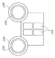
도 18은 여기에 설명된 특정 실시 예들에 따라 네 개의 열전 발전기를 갖는 촉매 변환장치의 측면도이다.
도 19는 열전 발전기 부의 뜨거운 면 및 전류 흐름의 기능으로서 열전 발전기 부를 가로지른 전압에 의해 흡수된 화력의 구성이다.
도 20은 여기에 설명된 특정 실시 예에 따라 열전 발전기와 통신하는 컨트롤러 및 열전 발전기 세그먼트의 작동을 최적화하기 위한 센서를 개략적으로 도시한다.
도 21은 도 3a에 도시된 배가 열 복원 시스템의 배경도이다.
도 22는 도 4a에 도시된 차가운 면 열 교환기의 배경도이다.Various embodiments are shown in the figures for purposes of illustration, but are not to be construed as limiting the scope of the invention. In addition, various features of different embodiments may be combined to form additional embodiments, which are a part of this application. Some features of the structure can be eliminated or omitted. Throughout the drawings, reference numerals can be reused to indicate similarities between reference materials.
Figure 1 shows an embodiment of a power generation system.
Figure 2 shows another embodiment of a power generation system.
Fig. 3A shows an incision view of the exhaust heat recovery system.
3B shows a cross-sectional view of the thermoelectric element assembly.
Figure 3c shows a cross-sectional view of a heat exchanger assembly.
4A is a cross-sectional view of a cold side heat exchanger.
4B is a side cross-sectional view of the cold side heat exchanger.
5 is a cross-sectional view of a heat transfer enhancement system in an exhaust tube.
6 is a diagram of thermoelement-attached shunts having thermoelectric elements attached thereto.
Figure 7 shows an embodiment of a flat thermoelectric generator.
8A is a diagram of thermoelectric elements at the high temperature end of the exhaust heat recovery system.
8B is a diagram of the thermoelectric elements in the middle section of the exhaust heat recovery system.
8C is a diagram of thermoelectric elements at the low temperature end of the exhaust heat recovery system.
Figure 9 is a diagram of thermoelectric elements in a stack configuration.
10 is a chart showing the relationship between temperature and time on the hot surface of the thermoelectric element.
11A is a background view of the thermoelectric element attachment ring.
11B is a background view of the thermoelectric element attachment ring.
12 is a diagram of a shunt with a thermoelectric element attached to a shell of an exhaust pipe.
13A-B are diagrams of a shunt with a thermoelectric element with the location of the structures arranged therein.
14 is a diagram of a shunt electrical joint on a cold surface of a thermoelectric element.
15A is a cross-sectional view of a catalytic converter illustrating a section of a heat exchanger and a thermoelectric generator according to certain embodiments described herein.
Fig. 15B is a side view of the catalytic converter of Fig. 15A.
16 is a partial cross-sectional view of a heat exchanger and thermoelectric generator structure showing various shunt structures in accordance with certain embodiments described herein.
Figure 17 is a partial cross-sectional view of a heat exchanger and thermoelectric generator structure illustrating various configurations of hot face assemblies and cold face assemblies in accordance with certain embodiments described herein.
18 is a side view of a catalytic converter having four thermoelectric generators in accordance with certain embodiments described herein.
19 is a configuration of the thermal power absorbed by the voltage across the thermoelectric generator as a function of the hot surface and current flow of the thermoelectric generator.
Figure 20 schematically illustrates a controller for communicating with a thermoelectric generator according to the specific embodiment described herein and a sensor for optimizing the operation of the thermoelectric generator segment.
FIG. 21 is a background view of the boat recovery system shown in FIG. 3A. FIG.
Figure 22 is a background view of the cold side heat exchanger shown in Figure 4a.
비록 여기에 특정 바람직한 실시 예들이 개시되나, 본 발명의 주제는 구체적으로 개시된 실시 예들을 넘어 다른 대안의 실시 예들 및/또는 사용들, 그리고 그것들의 변경들 및 등가물까지 확장한다. 따라서, 여기에 첨부된 청구항의 범위는 아래에 설명되는 특정 실시 예들에 의해 한정되지 않는다. 예를 들면, 여기에 개시된 어떤 방법 혹은 프로세스에서, 방법 또는 프로세스의 작용 혹은 작동은 어떤 적합한 순서로 실행될 수 있으며 반드시 어떤 특정하게 개시된 순서에 한정하는 것은 아니다. 특정 실시 예들의 이해에 도움이 될 수 있는 방식으로, 다양한 작동들이 다수의 별개의 작동으로서 설명될 수 있다; 그러나, 설명의 순서는 이러한 작동들이 순서 의존적이라는 것을 나타내는 것으로 이해되어서는 안 된다. 부가적으로, 여기에 설명되는 구조, 시스템, 및/또는 장치들은 통합된 부품 또는 개별 부품으로서 구현될 수 있다. 다양한 실시 예들을 비교하기 위하여, 이러한 실시 예들의 특정 양상 및 장점들이 설명된다. 그러한 모든 양상 및 장점들이 반드시 어떤 특정 실시 예에 의해 달성될 필요는 없다. 따라서, 예를 들면, 다양한 실시 예들은 반드시 여기에 또한 설명되거나 논의되는 다른 양상 혹은 장점들을 달성하지 않고 여기에 설명되는 하나의 양상 혹은 장점을 달성하거나 최적화하는 방식으로 수행될 수 있다.Although certain preferred embodiments are disclosed herein, the subject matter of the invention extends beyond the specifically disclosed embodiments to other alternative embodiments and / or uses, and modifications and equivalents thereof. Accordingly, the scope of the claims appended hereto is not limited by the specific embodiments described below. For example, in any method or process disclosed herein, the operation or operation of a method or process may be performed in any suitable order and is not necessarily limited to any specifically disclosed order. In a manner that may aid in understanding certain embodiments, various operations may be described as a number of distinct operations; However, the order of description should not be understood as indicating that these operations are order dependent. Additionally, the structures, systems, and / or devices described herein may be implemented as integrated or discrete components. In order to compare various embodiments, certain aspects and advantages of these embodiments are set forth. And all such aspects and advantages need not necessarily be accomplished by any particular embodiment. Thus, for example, various embodiments may be performed in a manner that accomplishes or optimizes one aspect or advantage described herein without necessarily achieving other aspects or advantages, which are also discussed or discussed herein.
열전 기반 발전은 산업용, 상업용, 주거용, 자동차용, 해양, 항공, 및 다른 적용분야에서 다양한 방식으로 사용될 수 있다. 예를 들면, 발전 열전 물질에서의 성능 향상 및 이산화탄소 배출 감소를 위한 정부 권한은 폐열 복원 시스템에서의 관심의 증가로 이어졌다. 특히, 승용차, 밴(van) 및 트럭 시장의 요구사항을 충족시키는 폐열 복원 시스템이 바람직하다. 바람직한 디자인들은 강인하고, 신뢰할 수 있으며, 적어도 15년 동안의 적절한 작동을 제공할 수 있으며, 경제적이다. 몇몇 실시 예들에서, 폐열 복원 시스템은 광범위한 질량 흐름을 수용하기 위하여 700℃에 이르는 온도에서의 배기 스트림에서 작동하여 이산화탄소 배출 감소에 중대한 기여를 함에 있어서 충분히 고효율적이다.Thermoelectric-based power generation can be used in a variety of ways in industrial, commercial, residential, automotive, marine, aviation, and other applications. For example, the governmental authority to improve performance and reduce carbon dioxide emissions in generating thermoelectric materials has led to increased interest in waste heat recovery systems. In particular, a waste heat recovery system that meets the requirements of the passenger car, van and truck markets is desirable. Preferred designs are robust, reliable, and can provide adequate operation for at least 15 years and are economical. In some embodiments, the waste heat recovery system is sufficiently efficient to operate in the exhaust stream at temperatures up to 700 占 폚 to make a significant contribution to the reduction of carbon dioxide emissions to accommodate a wide range of mass flows.
다음의 하나 혹은 그 이상을 다루는 열전 발전 실시 예들이 여기에 설명된다: 열전 장치의 뜨겁고 차가운 면들 사이의 차등 열 팽창, 열 인터페이스 처리, 전기적 분리 및 중복, 변화하는 온도 및 질량 유동률, 열전 부품, 환경 보호, 및/또는 제조능력을 위한 디자인. 실험실 테스트 결과는 개시된 시스템 디자인이 예상치 못하게 효과적이라는 것을 나타낸다. 배기 시스템 내에 위치한 폐열 복원 시스템은 자동차의 요구사항을 만족시킬 수 있으며 통상의 구동 조건 하에서 유용한 양의 전력을 제공할 수 있다.Thermoelectric generation embodiments that deal with one or more of the following are described herein: Differential thermal expansion between the hot and cold sides of a thermoelectric device, thermal interface processing, electrical isolation and redundancy, varying temperature and mass flow rates, thermoelectric components, Design for protection, and / or manufacturing capability. Laboratory test results indicate that the disclosed system design is unexpectedly effective. The waste heat recovery system located within the exhaust system can meet the requirements of automobiles and can provide a useful amount of power under normal driving conditions.
많은 정부들은 수송 산업이 적극적으로 화석 연료 소비를 다루고 이산화탄소 및 다른 그린하우스 가스를 포함하는 배출을 감소시키도록 요구한다. 유럽 연합, 중국, 일본 및 미국에서과 같은 대부분의 이산화탄소 조약들은 예정 기한까지 허용가능한 배기 및 연료 소비 레벨의 감소를 요구한다. 몇몇 실시 예들은 효율을 증가시키고 그린하우스 가스 배출을 제어함으로써 이러한 권한들을 다룬다. 여기에 개시된 실시 예들은 단일 서브시스템(subsystem)의 도입으로부터 커다란 효율성 개선을 위한 소스로서 유효한 것으로 알려져 왔다. 그러한 시스템들이 큰 성능 효과와 복잡성을 갖도록 하는 능력 및 시스템 통합 비용이 적어도 극복해야 할 이전의 일부 폐열 복원 기술에 대한 장벽들이었다. 예를 들면, 이러한 장벽들은 2상 유체(two phase fluid, 예를 들면, 랭킨(Rankine) 사이클) 혹은 고체 상태 폐열 복원 기술을 기초로 한 시스템에 존재하여 왔다.Many governments require the transport industry to actively address fossil fuel consumption and reduce emissions, including carbon dioxide and other green house gases. Most carbon monoxide treaties, such as those in the European Union, China, Japan and the United States, require a reduction in acceptable levels of exhaust and fuel consumption by the due date. Some embodiments deal with these rights by increasing efficiency and controlling greenhouse gas emissions. The embodiments disclosed herein have been found to be effective as sources for significant efficiency improvements from the introduction of a single subsystem. The ability to make such systems have greater performance effects and complexity, and the barriers to some previous waste heat recovery technology that system integration costs must at least be overcome. For example, these barriers have existed in systems based on two phase fluids (e.g., Rankine cycle) or solid state waste heat recovery techniques.
몇몇 요인들이 고체 상태 열전 시스템을 매력적으로 만들기 위하여 결합된다. 우선, 차량들은 감속 및 정지 동안의 엔진 오프(engine off) 작동과 같은 더 영리한 서브시스템의 사용 및 브레이크(재생 및 구동), 조향 시스템, 연료 펌프, 열 관리 서브시스템(예를 들면, 피티씨(PCT) 히터) 및 다른 장비를 포함하는 전기화 서브시스템의 채택을 통하여 배출을 감소시키기 위한 자동차 회사의 전략으로서 더 전기화되고 있다. 이러한 변화들은 이산화탄소 배출을 감소시키나, 평균적으로 운전 사이클을 통하여 더 많은 전력을 소비한다. 또한, 전력 부하는 도심 운전 사이클 동안 상당히 변화하는데, 따라서 전기 저장 능력이 더 중요하며 증가된 전력의 흐름이 관리되어야 한다. 몇몇 실시 예들이 기계적 동력 출력에 반대되는 것과 같이, 폐열을 직접 전력으로 변환시킴으로써 이러한 요인들을 다룬다. Several factors are combined to make the solid state thermoelectric system attractive. First of all, the vehicles are equipped with the use of smarter subsystems such as engine off operation during deceleration and stopping, as well as the use of brakes (regenerative and driven), steering systems, fuel pumps, thermal management subsystems (PCT) heaters) and other equipment to reduce emissions through the adoption of electrification subsystems. These changes reduce CO 2 emissions, but on average consume more power through the operating cycle. Also, the power load varies considerably during an urban driving cycle, so the electrical storage capability is more important and the increased power flow must be managed. Some embodiments address these factors by converting waste heat directly into power, as opposed to mechanical power output.
몇몇 실시 예들은 향상된 성능을 나타내는 열전 재료들을 통합한다. 향상된 열전 재료 성능은 역률(power factor)에서의 증가 및 중간 온도(300℃ 내지 600℃) 재료들에서의 열 전도성 감소를 포함하는 발전에 기인한다. 몇몇 실시 예들은 낮은 온도(0℃ 내지 300℃) 재료들에서의 감소된 열 전도성 기법을 사용하는 열전 재료들을 통합한다. 향상된 열전 재료들은 폐열로부터 생산되는 전력의 양을 증가시킬 수 있는데 따라서 효율성 개선에 커다란 기여를 하며, 그렇게 함으로써, 시스템 복잡성 혹은 크기를 증가시키지 않는다. 따라서, 전력 출력의 와트(watt) 당 비용이 감소될 수 있다. 또 다른 비용 감소는 더 적은 열전 재료를 사용하는 시스템 디자인 기법의 통합에 의해 설명되어 왔다.Some embodiments incorporate thermoelectric materials that exhibit improved performance. Improved thermoelectric material performance is due to developments including an increase in power factor and a decrease in thermal conductivity at intermediate temperatures (300 DEG C to 600 DEG C) materials. Some embodiments incorporate thermoelectric materials that use reduced thermal conductivity techniques in low temperature (0 DEG C to 300 DEG C) materials. Improved thermoelectric materials can increase the amount of power produced from the waste heat and thus make a significant contribution to the efficiency improvement and thus do not increase system complexity or size. Thus, the cost per watt of the power output can be reduced. Another cost reduction has been illustrated by the integration of system design techniques using less thermoelectric materials.
몇몇 실시 예들은 하나 혹은 그 이상의 다음의 기능들을 수행한다:Some embodiments perform one or more of the following functions:
1. 배기 시스템으로부터 광범위한 운전 조건 하에서 폐열을 효과적으로 수확한다(엔진 냉각수와는 대조적으로).1. Efficiently harvest waste heat from exhaust systems under a wide range of operating conditions (as opposed to engine coolant).
2. 정상의 운전 사이클 조건 혹은 장치 결함의 경우 하에서, 현재의 엔진 성능을 저하시키지 않는다.2. It does not deteriorate the current engine performance under normal operating cycle conditions or in the case of equipment failure.
3. 상당한 직접적인 작동 성능 개선을 달성하고 성능을 더 증가시키기 위하여(예를 들면, 효율을 증가시키고 차가운 열 분사 면으로서 엔진 냉각수 시스템을 사용하는 동안 편안한 사용자 가열 시간을 가속화하는 빠른 엔진 웜업(warm up)) 다른 차량 시스템과의 상호작용을 사용한다.3. In order to achieve significant direct operating performance improvements and to further increase performance (for example, a fast engine warm-up, which increases the efficiency and accelerates the comfortable user heating time while using the engine coolant system as a cool heat- )) Uses interaction with other vehicle systems.
4. 효율을 증가시키고 중량, 볼륨 및 비용을 감소시키기 위하여 촉매 변환장치, 머플러, 및/또는 배기 가스 재순환 시스템과 같은 존재하는 부품들을 대체하거나 통합한다.4. Replace or integrate existing components such as catalytic converters, mufflers, and / or exhaust gas recirculation systems to increase efficiency and reduce weight, volume, and cost.
5. 생산량의 경로 및 열전 재료들과 다른 주요 부품들의 수명 재활용의 종료를 입증한다.5. Demonstrate the end of life cycle recycling of production pathways and thermoelectric materials and other key components.
도 1은 복수의 열전 소자(130)들을 통합하는 발전 시스템(100)의 실시 예를 도시한다. 발전 시스템(100)은 더 큰 시스템의 부품일 수 있으며, 더 큰 시스템의 작동에 도움을 주기 위하여 전력을 제공하거나, 혹은 그렇지 않으면 성능을 증가시키거나, 혹은 더 큰 시스템의 작동을 제어하도록 구성될 수 있다. 발전 시스템(100)은 기능적으로 교환되는 하나 혹은 그 이상의 시스템을 지원하거나, 작용하거나, 혹은 제어할 수 있다. 특정 실시 예들에서, 발전 시스템(100)은 내부 부품들을 공유하는 또 다른 구조와 결합할 수 있으며, 그것들에 의해 감소된 부품의 수를 야기한다.FIG. 1 illustrates an embodiment of a
시스템(100)은 열 소스 및/또는 벽(120)과 열 전달하는 고온 영역(110)을 포함한다. 영역(110)의 온도는 열 소스, 열 전달 매체, 및 다른 요인들의 종류에 의해 결정될 수 있으며 시스템(100)의 작동 동안에 변경될 수 있거나 혹은 실질적으로 안정적일 수 있다. 특정 실시 예들에서, 전력 시스템(100)은 700℃, 혹은 그 이상의 온도까지에서 작동하도록 구성될 수 있다. 열 소스는 예를 들면, 고여 있거나 혹은 흐르는, 가열된 유체일 수 있다. 가열된 유체로부터의 열 에너지는 벽(120)과의 직접 접촉, 벽(120)과의 간접 접촉, 전도, 대류 등을 거쳐 벽(120)에 전달될 수 있다. 벽(120)으로의 열 에너지 전달은 또한 복사(radiation) 혹은 다른 프로세스를 통하여 발생할 수 있다.The
몇몇 실시 예들에서, 유체 열 소스는 대류에 의해 열 에너지 전달이 도움을 주는 것과 같이, 벽(120)에 근접하게 흐른다. 열 에너지 소스는 예를 들면, 전력 장비로부터의 폐열일 수 있다. 또 다른 예로서, 열 소스는 반응 챔버 혹은 그외에서 일어나는, 하나 혹은 그 이상의 화학 반응일 수 있다. 열 소스는 열 소스로부터 열 에너지의 소멸을 제한하거나 안내하는 인클로저(enclosure) 혹은 다른 구조 내에 포함될 수 있다. 예를 들면, 열 소스는 파이프, 챔버, 도관, 혹은 다른 인클로저 내에 포함될 수 있다. 벽(120)은 열 소스의 인클로저의 적어도 일부를 형성할 수 있다. 바람직하게는, 열 에너지는 열 소스로부터 벽(120)으로 향하는데 따라서 열 에너지는 전기 발전을 위하여 사용될 수 있다. 예를 들면, 열 소스는 열전 발전기의 하나 혹은 그 이상의 열전 소자를 가로질러 존재하기 위한 열 구배(thermal gradient)를 야기할 수 있다. 열전 발전기는 열 소스 및 열전 소자(130)들의 뜨거운 면 사이에 높은 열 전도성을 제공하기 위하여 어떤 적절한 방식으로 열 소스에 열적으로 결합될 수 있다.In some embodiments, the fluid heat source flows close to the
벽(120)은 도관, 파이프, 반응 챔버, 열교환기, 혹은 하우징의 그것과 같은, 모든 종류의 벽일 수 있다. 벽(120)은 열교환기 핀(fin), 벽의 표면 영역을 증가시키도록 구성된 구조, 또 다른 열교환기 구조, 혹은 구조들의 조합에 연결될 수 있다. 몇몇 실시 예들에서, 벽(120)은 하나 혹은 그 이상의 통합된 열교환기 구조들을 포함할 수 있다. 벽(120)은 높은 온도 영역(110) 및 열 에너지를 열전 소자(130)들로 향하게 하는 열교환기 구조 사이의 열 에너지 전달을 용이하게 하는 모든 적절한 방법으로 구성될 수 있다. 벽(120)은 평평하거나, 혹은 도 1에 도시된 것과 같이, 곡선형, 오목형, 불규칙형일 수 있거나, 혹은 또 다른 형태를 가질 수 있다. The
특정 실시 예들에서, 시스템(100)은 높은 전력 밀도 열전 소자 디자인, 스택(stack) 열전 소자 디자인, 혹은 다른 적합한 열전 소자 디자인을 사용한다. 특정 실시 예들은 전기적으로 분리된 열전 소자(130)들의 뱅크(bank)를 포함한다. 도 1의 실시 예는 스택 디자인에서 열전 소자(130)들과 열적 연결된 차가운 면(132) 및 뜨거운 면 션트(134)를 도시한다. 스택 디자인을 사용하는 적어도 일부의 열전 모듈 구성들은 예를 들면, 향상된 효율성을 위한 맞춤형 n 및 p 형 소자 기하학뿐만 아니라 열적 그리고 전기적 인터페이스를 위한 향상된 포괄적인 부하를 포함하는 다양한 장점을 제공할 수 있다.In certain embodiments, the
션트 그룹(132, 134)은 신뢰성 및 작동 전압의 적절한 균형을 달성하기 위하여 전기적으로 직렬/병렬 배열로 연결될 수 있다. 션트들은 열전 소자 안정성, 지속성, 및 신뢰성을 달성하기 위하여 다중의 열전 소자(130)들을 그룹을 지어 부착하기 위한 제공을 가질 수 있다. 몇몇 실시 예들에서, 뜨거운 면 열교환기의 열 전력 밀도 및 차가운 면 열교환기의 열 전력 밀도 사이의 차이는 감소되거나 혹은 최소화된다. 예를 들면, 션트들(132,134)은 뜨거운 그리고 차가운 면 열 교환기의 열 전력 밀도를 맞추도록 구성될 수 있다. 벽(120)으로부터의 열 에너지는 뜨거운 면 션트(134)를 거쳐 열전 소자들(130)로 전달될 수 있다. 차가운 면 션트(132)의 열 에너지는 주변 공기, 순환 냉각 시스템, 또 다른 냉각 구조에 노출된 열교환기 핀을 포함하는 어떤 적절한 기법, 혹은 기법들의 조합을 사용하여 소멸되거나 혹은 감소될 수 있다.
션트(132, 134)를 벽(120)에, 열전 소자들(130)에, 혹은 시스템(100)의 다른 구조체들에 열적으로 그리고 기계적으로 연결하기 위하여 다양한 기법들이 사용될 수 있다. 예를 들면, 고온 유리, 세라믹 접착제, 기계 잠금(슬롯, 핀 등을 사용하는), 브레이징(braising), 용접, 잠금(스크류, 볼트 등), 클립(clip), 브래킷(bracket), 다른 연결 기법, 혹은 기법들의 조합이 사용될 수 있다. 션트들은 또한 밴드(band) 혹은 벽(120) 주위를 주변으로 확장하는 다른 구조체에 의해 안전할 수 있다. 특정 실시 예들에서, 뜨거운 면 션트들은 벽(120)으로부터 전기적으로 분리된다. 다른 실시 예들에서, 션트들은 벽(120)으로부터 전기적으로 분리되지 않으며, 션트들은 통합된 전기 분리를 통합할 수 있다.Various techniques may be used to thermally and mechanically connect the
열전 소자들(130)은 서로 매우 근접하게 배열될 수 있으며, 이것에 의해 열전 소자들(130) 사이의 인터페이스에서의 전기적 연결을 용이하게 하며 전기적 네트워크를 생성한다. 몇몇 경우에 있어서, 열 팽창은 열전 소자들(130) 사이의 인터페이스에서의 조인트 보장 및 전도성을 손상시킬 수 있다. 몇몇 실시 예들에 있어서, 인접한 열전 소자들 사이의 연결 조인트 혹은 열전 소자들 및 션트들 사이의 연결 조인트는 열 팽창의 바람직하지 않은 효과들을 감소시키거나 최소화하도록 구성될 수 있다. 예를 들면, 열전 소자들의 길이, 구성, 형태, 수와 크기는 출력, 작동 온도, 작동 유체, 및 서로 다른 작동 환경에 대응하는 다른 특성들을 조절하도록 구성될 수 있다. 특정 실시 예들에서, 열전 소자들(130)의 그룹들은 개별적인 열전 소자들 혹은 열전 소자들의 그룹들이 땜납이 제거되거나 탈브레이징(de-braising) 없이 대체되거나 혹은 분해되는 것을 허용하는 방식으로 연결된다. 몇몇 실시 예들에서, 적어도 실(seal)의 특정 형태들은 높은 온도 영역(110)에 열적으로 근접하지 않는다. 대신에, 밀봉 재료들이 높은 온도 영역(110) 및 시스템(100)의 다른 고온 부품으로부터 분리되고, 절연되거나, 및/또는 열적으로 분리될 수 있다.The
열전 소자들(130)은 모든 적합한 열전 재료들을 포함할 수 있으며 재료들을 가로질러 적용된 온도 구배에 대응하는 전력을 발생하도록 구성될 수 있다. 몇몇 실시 예들은 향상된 성능을 나타내는 열전 재료들을 통합한다. 향상된 열전 재료 성능은 역률에서의 증가 및 중간 온도(300℃ 내지 600℃) 재료들에서 열 전도도에서의 감소를 포함하는 진전에 기인한다. 몇몇 실시 예들은 낮은 온도(0℃ 내지 300℃) 재료들에서 감소된 열 전도도를 사용하는 열전 재료들을 통합한다. 향상된 열전 재료들은 폐열로부터 생산되는 전력의 양을 증가시킬 수 있는데 따라서 효율성 개선에 커다란 기여를 하며, 그렇게 함으로써, 시스템 복잡성 혹은 크기를 증가시키지 않는다. 따라서, 전력 출력의 와트(watt) 당 비용이 감소될 수 있다. 또 다른 비용 감소는 더 적은 열전 재료를 사용하는 시스템 디자인 기법의 통합에 의해 설명되어 왔다.The
열전 소자 인터페이스는 인터페이스에서 경험하는 인장(tensile) 및 전단 응력(shesr stress)을 감소시키기 위하여, 스크린, 소결(sintered) 금속 구조, 금속 호일, 양각 호일(embossed foil), 고온 전기 전도성 그리스(grease), 혹은 다른 적합한 부재들과 같은, 순응 부재(compliant member)들을 포함할 수 있다. 순응 부재들은 압축 이음(compression fit), 결합 표면에서의 세부 잠금에 의해 결합되거나, 혹은 부착될 수 있다. 게다가, 인터페이스는 낮은 인터페이스 손실을 갖는 전류를 전달하는 순응 굴곡(compliant flexure)의 사용을 통하는 것과 같이 외부 힘의 적용에 의해 압축이 유지될 수 있다.The thermoelectric interface can be a screen, a sintered metal structure, a metal foil, an embossed foil, a high temperature electrically conductive grease, or the like to reduce the tensile and sheer stress experienced at the interface. , Or other suitable members. ≪ / RTI > The compliant members can be joined or attached by a compression fit, a detailed lock on the mating surface. In addition, the interface can be kept compressed by the application of an external force, such as through the use of compliant flexures that carry current with low interface loss.
열전 모듈의 차가운 면은 일반적으로 높은 온도 영역(110)보다 더 차가운 냉각 유체와 열 연결될 수 있으며, 열전 소자들(130)의 차가운 면 및 뜨거운 면 사이의 온도 구배를 생성한다. 냉각 유체는 주변 공기, 액체 냉각수, 또 다른 흐르거나 고여 있는 유체, 혹은 유체들의 조합일 수 있다. 냉각 유체는 도관 혹은 채널 내에 포함될 수 있으며, 유체는 열전 소자들(130)과 상당한 열 접촉을 달성하기 위하여 그러한 도관 혹은 채널을 통하여 향해질 수 있으며, 열전 소자들(130)의 차가운 면 및 냉각 유체 사이의 열 에너지 전달을 용이하게 한다. 열 에너지는 하나 혹은 그 이상의 차가운 면 션트(132)를 거쳐 전달될 수 있다. 열전 소자들(130)과 열 접촉하는 유체의 흐름 혹은 압력은 팬(fan), 펌프, 밸브, 유체 바이패스, 혹은 다른 수단 또는 수단들의 조합과 같은, 유체 조절기(fluid regulator)에 의해 영향을 받을 수 있다. 유체의 운동은 열전 소자들(130)로부터 유체로의 열 에너지 전달률을 증가시킬 수 있으며, 이것에 의해 열전 소재들의 뜨거운 면 및 차가운 면 사이의 온도차를 증가시킬 수 있다. 열교환기는 마찬가지로 열전 소자들의 차가운 면 및 유체 사이의 열 에너지 전달을 증가시킬 수 있다. 예를 들면, 핀은 열 에너지가 주변 유체 내로 나갈 수 있는 표면 영역을 증가시킬 수 있다.The cold side of the thermoelectric module can be thermally coupled to a cooling fluid that is generally cooler than the
시스템(100)의 부품들이 다른 무엇보다도, 열 소스 및 냉각 유체의 노출의 결과로 인하여 시간에 따른 온도의 변동을 경험함에 따라, 부품들은 다양한 양의 열 팽창을 견딜 수 있다. 시스템(100)의 부품들에 의해 경험되는 열 팽창의 양은 시스템의 열 구성 및 부품들이 구성되는 재료들에 따라 달라진다. 부품들은 특정 금속과 같이, 상대적으로 높은 열 팽창 계수를 갖는 재료들을 포함하는, 어떤 적절한 재료들 혹은 재료들의 조합으로 구성될 수 있다. 시스템의 뜨겁고 차가운 면들은 열 팽창의 상당히 이질적인 정도를 경험할 수 있으며, 시스템(100)은 실질적으로 광범위하게 변화하는 열 구성의 높은 성능 레벨을 유지하도록 구성될 수 있다.As components of
몇몇 실시 예들에서, 션트들(132, 134)은 열전 소재들을 가로지른 열 구배가 정상으로부터 멀리 떨어진 방향으로 향하는 것과 같이 시스템(100)을 통하여 열 에너지 흐름을 향하도록 구성된다. 예를 들면, 션트들은 열 구배가 벽(120)에 일반적으로 혹은 거의 평행한 것과 같이 도 1에 도시된 것과 같은 "T" 구성을 사용할 수 있다. 그러한 구성에서, 열전 소자들(130) 및 다른 시스템 부품들 사이의 차이의 변화가 감소되거나 혹은 제거되는 동안에 온도 변화에 기인한 부품들의 치수 변화가 발생할 수 있다. 또한, 열전 발전기의 외부 표면은 높은 열 전도도, 전체 제조 및 작동 온도 범위에 걸쳐 안정적인 전기적 절연 코팅으로 처리될 수 있다.In some embodiments, the
도 2는 발전 시스템(150)의 또 다른 실시 예를 도시한다. 도 2에 도시된 실시 예는 적어도 부분적으로 높은 온도 영역(152)을 둘러싸는, 일반적으로 실린더 형태의 벽(154)을 포함한다. 높은 온도 영역은 열 소스에 연결될 수 있거나 혹은 열 소스를 포함할 수 있다. 예를 들면, 유체는 실린더 형태의 벽(154)에 의해 형성된 둘러싸인 도관 내에 흐를 수 있다. 하나 혹은 그 이상의 열전 소자들(156)은 벽(154)의 주변을 따라 세로로 배열될 수 있다. 도 2에 도시된 실시 예에서, 비록 열전 소자들(156)이 완전히 벽(154) 주위를 확장할 수 있으며 실제로 벽(154)의 외부 표면을 덮도록 구성될 수 있다고 생각되더라도, 열전 소자들의 어레이(array)는 실린더 형태의 벽(154) 일부를 둘러싼다.FIG. 2 shows another embodiment of the
몇몇 실시 예들에서, 열교환기(도시되지 않음)는 높은 온도 영역(152)으로부터 열전 소자들(156)을 향하여 열 에너지의 전달을 용이하게 하기 위하여 적어도 부분적으로 높은 온도 영역(152) 내에 배열될 수 있다. 열교환기는 좋은 열 전달을 제공하는 모든 기법에 의해 벽(154) 혹은 열전 소자들(156)에 부착될 수 있다. 특정 실시 예들에서, 열교환기는 벽(154) 내로 통합된다.In some embodiments, a heat exchanger (not shown) may be arranged in the at least partially
일반적으로 실린더 형태의 벽(154) 내부 공간은 하나 혹은 그 이상의 유체 도관으로 분할될 수 있다. 하나 혹은 그 이상의 유체 도관은 높은 온도 영역(152) 혹은 벽(154) 내부의 다른 영역을 통하여 유체의 흐름을 조절하도록 구성될 수 있다. 몇몇 실시 예들에서, 발전 시스템(150)은 용량을 조절하고, 형성 요인 조건을 만족시키며 비용을 감소하기 위하거나, 혹은 다른 이유로 다중의 실린더를 사용할 수 있다. 특정 실시 예들에서, 시스템(150)은 실린더 형태가 아닌 벽을 포함한다; 대신에, 높은 온도 영역은 적어도 부분적으로 계란, 타원, 별, 원뿔, 나선, 다각형, 또 다른 형태, 혹은 그것들의 조합의 형태를 갖는 벽에 의해 둘러싸일 수 있다.In general, the interior space of the
여기에 개시된 열전 발전기의 실시 예들은 배기 시스템 열 복원과 같은, 하나 혹은 그 이상의 특정 적용을 참조하여 설명된다. 개시된 실시 예들의 적어도 일부 혹은 개시된 실시 예들의 양상은 열 에너지가 전기 에너지로 바람직하게 전환할 수 있는 다른 적용 또는 환경에 적용될 수 있다.Embodiments of the thermoelectric generators disclosed herein are described with reference to one or more specific applications, such as exhaust system thermal recovery. At least some of the disclosed embodiments or aspects of the disclosed embodiments may be applied to other applications or environments in which thermal energy is preferably capable of being converted to electrical energy.
도 3a는 열전 발전기를 사용하는 배기 열 복원 시스템(200)을 도시한다. 시스템(200)은 내부 챔버(202)를 통하여 도관으로 연결된 뜨거운 배기를 갖는, 일반적으로 실린더 형태일 수 있는 쉘(210), 및 쉘(210)의 일부를 둘러싸는 열전 소자들(206)의 어레이들(204a-c)을 포함한다. 도 21은 일반적으로 실린더형 구성의 열전 발전기 시스템(200)을 도시한 배경도이다. 도시된 배기 튜브(212)의 쉘(210)은 실린더형이나, 다른 적합한 튜브 기하학적 구조도 사용될 수 있다는 것을 이해하여야 한다. 도 4a 및 4b에 도시된, 차가운 면 열교환기(208)는 뜨거운 면 쉘(210)의 외부에 있으며 냉각 및 폐열 제거를 제공한다. 배기 튜브(212)는 배기 스트림으로부터의 열 전달을 향상시키기 위하여 도 5에 도시된 것과 같이, 내부 열교환기(214)를 갖는다. 배기 튜브(212)의 중심 부는 낮은 배기 유체 압력 강하를 갖는 제 2 영역(218)을 가질 수 있다. 제 2 영역(218)은 만일 배기 유체 유동률이 허용가능한 한도를 넘는 역압을 야기할 정도로 충분히 크게 되면 바이패스로서 작용할 수 있다.FIG. 3A shows an exhaust
몇몇 실시 예들에서, 중심 부(218)는 도 5에 도시된 것과 같이, 허용가능한 압력 강하의 한도 내에서 열 전달 향상 구조체(heat transfer enhancement structure, 220)를 갖는다. 제 2 영역(218) 내의 열 전달 구조체(220)는 실질적으로 열 전달 영역 열교환기(214)보다 밀도가 낮을 수 있다. 슬리브(sleeve, 222)는 배기 유체로부터 열 전달을 더 잘 향하게 하고 제어하기 위하여 배기 튜브(212) 내의 두 개의 흐름 경로를 분리할 수 있다. 도시된 실시 예는 쉘(210)과 배기 튜브(212)의 내부 슬리브(222)의 면적 및/또는 상대 크기를 조절함으로써 변경되거나 조절될 수 있다. 또한, 출력 및 작동 온도와 다양한 작동 유체와 같은, 다른 특성들을 조절하고, 서로 다른 작동 환경에 반응하기 위하여 튜브(212) 외부의 열전 소자들(206)의 길이, 구성, 형태, 수와 크기가 선택될 수 있다. 또한 용량을 조절하고, 형성 요인 조건을 만족시키며 비용을 감소하기 위하거나, 혹은 다른 이유로 다중의 튜브들(도시되지 않음)이 사용할 수 있다. 몇몇 실시 예들은 계란, 타원, 별, 원뿔, 나선 혹은 그 외의 일반적으로 실린더 형태의 실린더를 포함한다.In some embodiments, the
다음의 설명에서, 몇몇 실시 예들의 특징들이 논의되며 예상치 못한 디자인 도전의 해결책이 개시된다. 성공적으로 만든 디자인의 일부 특징들은 도 7에 도시된 것과 같은 평평한 열전 발전기 구성에 적용될 수 있다. 몇몇 실시 예들은 여기에 설명되는 개량을 사용하는 평평한 열전 발전기(700)를 포함한다. 평평한 열전 발전기(700)는 뜨거운 작동 유체 도관 네트워크(702) 및 차가운 작동 유체 도관 네트워크(704)를 포함할 수 있다. 하나 혹은 그 이상의 열전 소자들(706)은 작동 유체 도관 네트워크들(702, 704) 사이에 배열될 수 있다. 열전 소자들(706)은 하나 혹은 그 이상의 실질적으로 평면의 레벨 내에 배열될 수 있다.In the following description, features of some embodiments are discussed and a solution to unexpected design challenges is disclosed. Some features of a successfully made design can be applied to a flat thermoelectric generator configuration as shown in FIG. Some embodiments include a flat
열전 발전기(200)는 다양한 제어 특징들을 갖는다. 일부 제어 특징들은 열전 발전기(200) 자체의 작동에 영향을 줄 수 있다. 예를 들면, 컨트롤러(controller)는 배기 튜브(212)의 제 2 영역(218) 내부에 배열된 하나 혹은 그 이상의 밸브(224)를 구동하도록 구성될 수 있다. 하나 혹은 그 이상의 밸브(224)는 도 3a에 도시된 것과 같이, 튜브(212) 내의 배기 유체 흐름을 할당하도록 구성될 수 있다. 또 다른 예로서, 열전 소자들(206)의 섹션들(204a, 204b,204c)은 도 8a, 8b 및 8c에 도시된 것과 같이, 독립적인 전력 출력을 가질 수 있다. 열전 소자들(206)은 유체 스트림으로부터 화력(thermal power)을 거의 추출할 수 있으며 열전 발전기(200)의 적어도 일부를 통과할 때 유체의 적어도 일부에서의 온도 강하를 변경시킨다. 열전 발전기는 다른 시스템의 작동에 영향을 주고, 영향을 미치며, 및/또는 제어할 수 있다. 예를 들면, 열전 발전기는 머플러(muffler)를 대체하거나 보완하기 위한 소음 감소에 도움을 줄 수 있고, 사용자 및/또는 엔진 웜업의 속도를 증가시킬 수 있으며, 촉매 변환장치 웜업 및 온도 제어를 실행할 수 있으며, 엔진 냉각 시스템으로의 열 전달을 실행할 수 있으며, 전기 에너지 기능(예를 들면, 출력 전력, 전압, 사용 및 제어)을 구현할 수 있으며, 배기 가스 복원 시스템 가스 온도를 제어할 수 있으며, 열전 발전기와 기능적으로 연결되어 통합되거나 및/또는 위치될 수 있는 다른 제어 혹은 상호작용에 도움을 줄 수 있다.The
몇몇 실시 예들은 하나 혹은 그 이상의 경비 감소 및 단순화 특징을 포함한다. 높은 전력 밀도 열전 디자인, 도 9에 도시된 것과 같은 스택 디자인, 열전 발전기 구성, 및 차량 내로의 열전 발전기 통합이 개시된 열전 발전기 시스템에서의 특징들을 적용하고, 변경하며, 사용하는데 익숙한 개량의 관점에서 설명된다. 단순화 특징들은 열전 소자들을 단일로 및/또는 분리된 모듈에 배치하는 것보다는, 도 11a 및 11b에 도시된 것과 같이, 링 구성(1100a, 1100b) 내에 배치하는 것을 포함한다. 링(ring, 1100)은 내장된 부재(1108)로부터 구성될 수 있거나 혹은 하나 혹은 그 이상의 갭(gap, 1106)에 의해 분리된 복수의 링 부재(1102, 1104)로부터 구성될 수 있다. 갭(1106)은 전기적으로 혹은 열적으로 링 부재들(1102, 1104)을 서로 분리하도록 구성될 수 있다. 추가적인 단순화 특징들은 하나 혹은 그 이상의 유체 제어 밸브의 통합 및 열전 발전기의 다른 시스템(예를 들면, 머플러 혹은 다른 배기 시스템 부품)과의 결합을 포함할 수 있다.Some embodiments include one or more cost reduction and simplification features. The high power density thermoelectric design, the stack design as shown in FIG. 9, the thermoelectric generator configuration, and thermoelectric generator integration into the vehicle are described in terms of improvements that are familiar to apply, modify, and use features in the thermoelectric generator system do. Simplifying features include placing the thermoelectric elements in
예로서, 종래의 일부 열전 발전기 디자인들은 열전 발전기 시스템의 부품 사이(예를 들면, 열전 소자들 및 션트들 사이와 같은)의 접촉을 유지하기 위하여 높은 외부 힘이 적용되는 것을 요구한다. 특정 실시 예들에서, 도 4a에 도시된, 순응 굴곡(228)으로부터의 힘은 외부 부하를 대체할 수 있다. 또 다른 예로서, 일반적으로 실린더 형태를 갖는 열전 모듈(230)은 두 개의 단(232, 234)에서를 제외하고는 시스템(200)의 모서리 상의 고온 실의 사용을 감소시키거나 제거할 수 있다. 도 3a에 도시된 실시 예에서 사용된 실(236)은 저온에서의 탄성 실을 허용하기 위하여 실 기하학적 구조의 열 관리와 결합하여 고온에서 용접되거나 브레이징된 실의 사용에 의해 밀봉을 단순화한다. 또한, 열전 발전기 시스템의 실린더 형태 및 열전 부착 특징부들은 큰 영역에 걸쳐 평평한 열 전달의 사용을 감소시키거나 제거함으로써 뜨거운 면에서 차가운 면 열 전달을 단순화한다.By way of example, some conventional thermoelectric generator designs require high external forces to be applied to maintain contact between components of a thermoelectric generator system (e.g., between thermoelectric elements and shunts). In certain embodiments, the force from conforming
여기에 설명된 특징들의 적어도 일부는 열전 발전기 시스템(200)의 효율성을 증가시킨다. 예를 들면, 열전 소자들(206) 단들에서, 도 6에 도시된 클래드(clad) 열교환기 표면, 열전이 전기적으로 분리된 뱅크, 유체 화력 추출의 방향을 따른 열 분리, 및 순응 전기 인터페이스(240)가 열전 모듈 기판들을 대체하여 사용될 수 있다. 순응 부재들(240)은 열전 소자들(206)과 션트들(238) 사이의 인터페이스에서 인장 및 전단 응력을 감소시킬 수 있다. 순응 부재들(240)은 예를 들면, 스크린, 소결 금속 구조, 금속 호일, 양각 호일, 고온 전기 전도성 그리스, 다른 재료들, 혹은 재료들의 조합을 포함하는, 다른 적합한 재료들로부터 만들어질 수 있다. 순응 부재들(240)은 압축 이음, 결합 표면에서의 세부 잠금에 의해 결합되거나, 혹은 부착될 수 있다. 순응 부재들(240)은 열전 소자들(206)을 위치시키는데 도움을 주는 하나 혹은 그 이상의 돌출부(protrusion, 242)를 포함할 수 있다. 몇몇 실시 예들에서, 션트들(238) 및 열전 소자들(206) 사이의 인터페이스는 도 4a에 도시된 것과 같이, 순응 굴곡(228)의 사용을 통하는 것과 같은 외부 힘의 적용에 의해 압축이 유지될 수 있다.At least some of the features described herein increase the efficiency of the
몇몇 실시 예들에서, 열전 발전기 시스템(200)은 하나 혹은 그 이상의 제조능 및 재활용능 특성을 포함한다. 예로서, 열전 소자 그룹(204a-c)은 기계적으로 부착될 수 있는데, 따라서 그것들이 땜납이 제거되거나 탈브레이징 없이 대체되거나 혹은 분해되는 것을 허용한다. 또한, 열전 발전기 시스템(200)은 일반적으로 실린더 형태일 수 있으며, 그것에 의해 크고 평평한 표면의 사용 및 차가운 면에 열적으로 근접한 복잡한 실의 사용을 감소시키거나 제거할 수 있다. 몇몇 실시 예들에서, 종래의 밀봉 재료들이 열전 발전기 시스템(200)과 함께 사용될 수 있다.In some embodiments, the
몇몇 실시 예들에서, 도 3a에 도시된 열전 발전기 시스템(200)은 700℃까지의 배기 온도로 작동하는 차량 배기 시스템 내로 잘 통합할 수 있는 형태 요인에서 전술한 목적들을 충족시킨다. 실린더 형태는 효율적인 뜨거운 면 열 전달을 달성하고, 뜨겁고 차가운 면 사이의 큰 열 팽창 부조화를 다루며, 밀봉 복잡성을 감소시키는 저비용 해결책을 허용할 수 있다. 디자인은 감소된 크기, 감소된 중량, 감소된 비용, 증가된 출력, 및/또는 증가된 효율과 같은 장점을 달성하기 위하여 열전 발전기가 배기 전달 파이프 내의 분리된 부품일 수 있는 구성 제품군을 대표하거나 혹은 다른 부품들과 통합될 수 있다.In some embodiments, the
몇몇 실시 예들에서, 열전 발전기는 배기 시스템의 일부이며 적어도 하나의 머플러를 대체하기 위하여 위치되거나 디자인될 수 있다. 열전 발전기는 배기 시스템으로부터 화력을 추출하고 배기 스트림 온도를 낮추기 때문에, 흐름 속도 및 역압이 감소될 수 있다. 예를 들면, 만일 배기 튜브의 기하학적 구조가 가스 온도에서의 감소를 제외하고 변하지 않는다면 이러한 특징들이 나타난다. 또한, 머플러 자체는 그것의 기능성을 제거하거나 감소시킴으로써 역압을 유도하기 때문에, 열전 발전기는 적절한 디자인으로, 더 높은 열 전달 계수를 허용하는 흐름에 대한 더 높은 저항을 가질 수 있다. 따라서, 배기 가스로부터 화력의 추출이 증가된다.In some embodiments, the thermoelectric generator is part of an exhaust system and may be located or designed to replace at least one muffler. Because thermoelectric generators extract thermal power from the exhaust system and lower the exhaust stream temperature, the flow rate and back pressure can be reduced. For example, these features appear if the geometry of the exhaust tube does not change except for a reduction in gas temperature. Also, since the muffler itself induces back pressure by eliminating or reducing its functionality, the thermoelectric generator may have a higher resistance to flow allowing a higher heat transfer coefficient, with a proper design. Therefore, the extraction of the thermal power from the exhaust gas is increased.
몇몇 실시 예들에서, 열전 발전기는 촉매 변환장치와 결합하는데, 이는 하나 혹은 그 이상의 장점에 이르게 한다. 예를 들면, 촉매 변환장치의 일부는 이전에 설명된 열전 발전기 시스템(200) 부품들의 적어도 일부를 대신하여 사용할 수 있는데, 이는 부품 수의 감소를 야기한다. 또 다른 실시 예로서, 변환장치 및 열전 발전기 사이의 열 손실이 감소될 수 있는데, 이는 열전 발전기 내의 높은 가스 온도를 야기한다. 더 높은 배기 스트림 온도는 잠재적으로 열전 발전기 시스템의 효율 및/또는 전력 출력을 올릴 수 있다. 또한, 변환장치의 내부 부품들이 부품 중복을 제거하기 위하여 사용될 수 있다. 예를 들면, 하우징 및 실의 적어도 일부는 변환장치의 촉매 홀더 구조체의 부품을 공유할 수 있다. 열전 발전기 시스템은 또한 변환장치를 더 빨리 가열하기 위하여 열 피드백 및/또는 전력을 제공함으로써 변환장치 웜업을 가속화하는 통합된 기능을 제공할 수 있다. 열전 발전기 시스템에 촉매 변환장치를 추가함으로써, 내부와 외부 브래킷 류 및 다른 부착 특징부들이 감소될 수 있다. 또한 변환장치와의 통합은 열전 발전기의 일부가 엔진 및 변환장치 사이에 위치되는 것을 허용한다. 그러한 위치는 열전 발전기 일부의 작동 온도를 증가시킬 수 있으며, 열전 발전기가 작동 온도에 도달하는데 걸리는 시간을 감소시킬 수 있거나, 및/또는 촉매 변환장치가 열전 발전기의 적어도 일부에 의해 제어되려는 것을 허용할 수 있다.In some embodiments, the thermoelectric generator is associated with a catalytic converter, which leads to one or more advantages. For example, a portion of the catalytic converter can be used in place of at least a portion of the previously described
배기 가스 복원 시스템이 또한 개별 부품들의 복잡성에서 유사한 절감을 갖는 열전 발전기와 통합할 수 있다. 배기 가스 복원 시스템은 배기 가스의 일부를 냉각하기 위하여 엔진 냉각제를 사용하기 때문에, 열전 소자들의 차가운 면으로부터 폐열을 제거하기 위하여 동일한 냉각 시스템이 적용될 수 있다. 배기 가스 복원 시스템과 함께, 배기 가스 밸브는 또한 디자인을 단순화하기 위하여 열전 발전기 밸브에 근접하게 결합될 수 있다. 배기 가스 복원 시스템은 배기 시스템에 역압을 추가하는데, 따라서 조합은 어느 정도의 중복을 감소시키며 그것에 의해 역압 손실을 감소시킬 수 있거나 및/또는 열 전달을 증가시킬 수 있다.The exhaust gas restoration system can also be integrated with a thermoelectric generator having similar savings in the complexity of the individual components. Since the exhaust gas restoration system uses engine coolant to cool a portion of the exhaust gas, the same cooling system can be applied to remove waste heat from the cold side of the thermoelectric elements. In combination with the exhaust gas restoration system, the exhaust gas valve can also be coupled to the thermoelectric generator valve in close proximity to simplify the design. The exhaust gas restoration system adds back pressure to the exhaust system so that the combination can reduce some redundancy and thereby reduce back pressure loss and / or increase heat transfer.
몇몇 실시 예들에서, 열전 발전기 시스템은 최근의 배기 시스템 제품에서 성공적으로 증명된 현재의 차량 재료들 및 디자인 원리를 사용한다.In some embodiments, thermoelectric generator systems use current vehicle materials and design principles that have been successfully demonstrated in recent exhaust system products.
도 3a는 열전 발전기(200)의 단면도를 도시한다. 가장 안쪽의 챔버(218)는 부착된 엔진(도시되지 않음)의 디자인 한도 내에서 역압을 유지하는 동안 가장 높은 작동 배기 질량 유동률을 수용하는 배기 바이패스이다. 도 3a에 도시된, 버터플라이 밸브(butterfly valve, 224) 혹은 다른 바람직한 배기 가스 유동 디렉터(flow director)는 바이패스(218) 및 뜨거운 면 열교환기 코어(216) 사이의 배기 가스 흐름을 조절하기 위하여 열전 발전기(200)의 차가운 단(234)에 위치된다. 내부 슬리브(222)는 열교환기(214) 및 가장 안쪽의 챔버(218) 사이의 가스 흐름을 분리하기 위하여 열교환기(214)의 내부 표면을 라이닝(lining)할 수 있다. 밸브(224)는 배기 온도 및 질량 유동률의 작동 범위 하에서 배기 스트림으로부터 열 추출을 최적화하는 동안 디자인 한도 내에서 역압을 유지하기 위하여 흐름을 분할할 수 있다.FIG. 3A shows a cross-sectional view of a
도 5에 도시된 실시 예에서, 예를 들면, 핀과 같은 열교환기 구조체(220)는 바이패스 영역 내에 위치되며, 슬리브(222), 뜨거운 면 열교환기 코어(216) 및 뜨거운 면 쉘(210)과 좋은 열 접촉을 한다. 그러한 특징들은 바이패스 밸브(224)가 부분적으로 혹은 완전히 내부 코어(218)에서의 배기 가스 흐름을 허용하는 위치에 있을 때 낮은 역압에서의 화력 추출을 향상시킬 수 있다. 열교환기 구조체(220)는 양 면상에 AISI 316 스텐레스 강(DIN 1,4401)을 갖는 구리 코어 클래드로 구성될 수 있다. 열전 발전기 디자인 기준을 충족하는 스텐레스 클래드 니켈 혹은 탄소, 세라믹 조성물과 같은 다른 물질 혹은 물질 조합이 또한 사용될 수 있다. 바람직하게는, 열교환기 구조체(220)는 뜨거운 면 열전 발전기 쉘(210)의 내부 표면에 브레이징될 수 있으나, 좋은 열 전달을 제공하는 다른 방법에 의해 부착될 수도 있다. 쉘(210)은 316 스텐레스 강, 또 다른 적합한 재료, 혹은 재료들의 조합으로 구성될 수 있다.5, a
특정 실시 예들에서, 열전 발전기(200)의 재료 시스템은 스텐레스 강의 화학적 보호와 강도(예를 들면 내구성 및 수명) 및 구리의 높은 열 전도성(예를 들면 효율적 열 전도와 전달) 사이의 바람직한 절충을 제공하도록 구성된다. 대안으로서, 열교환기 및/또는 쉘 및/또는 내부 슬리브는 높은 열 전도성 세라믹, 질화 규소(silicon nitride), 알루미늄, 또 다른 효과적인 열교환 재료, 혹은 재료들의 조합과 같은, 다른 재료들로 구성될 수 있다. 열교환기(214, 220)는 또한 쉘(210)과 통합될 수 있다. 예를 들면, 몇몇 실시 예들에서, 열교환기(214, 220)는 세라믹 혹은 금속으로부터 주물 혹은 압출된다. 표면 영역 및 열 전달 계수를 증가시키기 위하여 뜨거운 면 쉘(210)을 구불구불하게 하거나 혹은 특별한 질감이 나게 하며, 외부 쉘을 형성하기 위하여 다중 튜브를 통합하거나, 혹은 배기 가스로부터 쉘을 통한 열 전달을 향상시키는 다른 방법을 이용하는 것과 같이, 열교환기의 동일한 목적을 달성하기 위한 다른 방법들도 가능하다.In certain embodiments, the material system of the
열전 발전기(200)를 만드는 방법의 예가 설명될 것이다. 쉘(210)의 외부 표면은 높은 열 전도성, 전체 구성에 걸쳐 안정한 전기적 절연 코팅 및 작동 온도 범위로 처리될 수 있다. 예를 들면, 쉘은 K-Tech 28 상표의 코팅, 플라스마 용사한(plasma sprayed) 알루미늄, 질화 알루미늄, 혹은 디자인 목적을 충족하는 다른 내구성의 코팅으로 코팅될 수 있다. 코팅의 대안으로서, 쉘(210)은 예를 들면, 아래에 설명되는 것과 같이(도 12 참조), 만일 전극 구조체 내에 전기 분리가 달성되면 코팅되지 않을 수 있다. 도 11a 및 11b에 도시된 것과 같이, 열 전도 션트들(1100a, 1100b)은 쉘에 부착될 수 있다. 션트들(1100a, 1100b)은 열전 소자들(206)에 뜨거운 면의 열적 및 전기적 연결을 형성한다. 뜨거운 면 쉘(210) 표면은 기계적 안정성 및 높은 열 전도성 모두를 달성하기 위하여 쉘을 션트에 결합하는 금속 재료 시스템으로 코팅될 수 있다. 예를 들면, 쉘(210, K-Tech 코팅)은 약 0.3 마이크론 두께의 티타늄으로 금속화될 수 있으며, 약 2 마이크론 두께의 저인(low phosphorus) 무전극 니켈 및 15 마이크론 두께의 티타늄으로 도금될 수 있다. 마찬가지로, 다른 적합한 결합제 및 재료 두께 혹은 그것들의 조합이 사용될 수 있다. 구리 합금 션트들(244)은 그때 500℃에서 티타늄을 구리와 반응 결합함으로써 쉘과 좋은 열 접촉 상태에 놓일 수 있다. 션트들(244)은 쉘을 둘러싸는 링 내로 형성될 수 있다. 링은 그것들을 팽창하기 위하여 약 250℃까지 가열되며, 가열되는 동안, 차가운 쉘을 미끄러져 가며 디자인 위치에 위치된다. 링은 압축 이음을 형성하기 위하여 냉각되고 줄어든다. 그 다음의 500℃에서의 열간 유지(heat soak)가 링을 적당한 위치에 결합시킨다.An example of how to make the
션트들(244)을 쉘(210) 구조체에 열적으로 그리고 기계적으로 부착하기 위하여 다른 기법들이 사용될 수 있다. 예를 들면, 고온 유리, 세라믹 접착제, 기계 잠금(슬롯, 핀 등을 사용하는), 브레이징, 용접 혹은 다른 방법들이 사용될 수 있다. 만일 션트들(244)이 쉘로부터 전기적으로 분리되지 않으면, 션트들(244)은 도 12에 도시된 것과 같이, 그것들의 구조체 내에 전기 분리를 포함할 수 있다. 예를 들면, 션트들은 미국 Arcansas주 Hot Springs 소재의 Bodycote K-Tech사로부터 이용가능한 K-Tech 28 코팅으로 코팅될 수 있다. 또한, 션트들은 라미네이트될 수 있거나 혹은 열전 소자들에 전기 분리 및 좋은 열 전도성을 제공하는 다른 재료 시스템일 수 있다. 션트들(244)은 도 12 및 13a-13b에 도시된 것과 같이, 스텐레스 강 혹은 다른 재료로 만들어진 하나 혹은 그 이상의 밴드들(248)과 함께 고정될 수 있으며, 밴드들(248)은 유리섬유 직물, 운모 혹은 다른 적합한 절연물과 같이, 고온 전기 절연체로 션트들(244)로부터 전기적으로 분리될 수 있다.Other techniques may be used to thermally and mechanically attach the
링(1100a) 내에 형성된 션트들(244)은 도 11a에 도시된 것과 같이, 병렬로 많은 열전 소자들을 가질 수 있다. 대안으로서, 서클(circle)의 섹션들(1102, 1104, 아크들)일 수 있는데, 따라서 하나 혹은 그 이상의 열전 소자들(206)은 병렬이며, 몇몇 아크(arc)들은 도 11b에 도시된 것과 같이, 분리된 전기 경로일 수 있다. 예를 들면, 몇몇 아크들(1102, 1104)은 장치의 출력 전압을 증가시키기 위하여 전기적으로 직렬일 수 있다. 션트들(244) 그룹은 신뢰성 및 작동 전압의 적절한 균형을 달성하기 위하여 전기적으로 직렬/병렬 배열로 연결될 수 있다. 션트들은 열전 소자 안정성, 지속성, 및 신뢰성을 달성하고 뜨겁고 차가운 면 열교환기의 화력 밀도를 맞추기 위하여 다중의 열전 소자(206)들을 그룹을 지어 부착하기 위한 제공을 가질 수 있다. The
작동 조건의 의도된 범위를 위한 디자인을 최적화하기 위하여 컴퓨터 모델이 사용될 수 있다. 모델은 동시에 변환 효율을 최대화하고 중량을 최소화한다. 바람직한 디자인에 있어서, 소자들(206)은 각각의 링(1100) 주변 주위에 네 개의 16 그룹으로 클러스터링된다. 고온 단(204a)에서, 열전 소자들은 분절되며 약 5㎜ 길이이다. 반대편 단(204c)에서, 그것들은 약 2㎜ 길이이다(예를 들면, 고온 단(204a)에서의 열전 소자들의 길이의 약 반 이하이거나 혹은 반과 동일한). 열전 소자들(206)은 분절될 수 있으며 약 200℃ 및 600℃ 사이에서 작동하는 부를 위하여 적합하게 투여된 텔루르화 납(lead telluride)으로부터 구성될 수 있으며 약 250℃까지 작동하는 부를 위하여 텔루르화 비스무스(bismuth telluride)가 투여될 수 있다.Computer models can be used to optimize the design for the intended range of operating conditions. The model simultaneously maximizes conversion efficiency and minimizes weight. In a preferred design,
열전 소자들(206)의 길이(226a-c)는 한계 이하의 응력을 유지하는 동안에, 각각의 소자(206)로부터 전력 생산을 최대화하도록 선택될 수 있다. 열전 발전기(200)는 도 8a, 8b 및 8c에 도시된 것과 같이, 열전 소자들을 통하여 낮은 전단 및 정상 응력을 적당히 유지하는 동안, 두 뜨겁고 차가운 단들에 낮은 계면 전기 및 열 저항을 제공하도록 구성된다. 프로토타입(prototype) 시스템을 위한 타겟 사이클 주기에 대한 안정적인 작동을 입증하기 위하여 열 사이클 연구들이 수행되었다. 열 사이클 테스트의 결과는 2 단계 세그먼트화 열전 소자들(p: 2.4㎜ × 3.75㎜ × 4.4㎜, n: 2.4㎜ × 3.75㎜ × 4.8㎜)이 적어도 약 300 열 사이클에 걸쳐 일관된 전력 생산을 제공한다는 것을 나타내었다. 연구에 사용된 세 가지 바람직한 열 사이클의 프로파일이 도 10에 도시된다. 따라서, 열전 소자 중량 및 전력 밀도는 대략 전류 흐름의 방향으로 소자 길이의 제곱에 반비례한다. 비용은 일반적으로 열전 재료 중량에 비례한다. 몇몇 실시 예들에서, 배기 스트림으로부터의 열 및 차가운 면으로부터의 방열(heat rejection)의 균형과 결합하여, 열전 발전기 길이에 따른 각각의 최대 온도차에 대하여 열전 소자들에 대한 최소 길이가 설정된다.The length 226a-c of the
특정 실시 예들에서, 차가운 면 션트(256) 및 열교환기(208)는 전력을 일반적으로 축 방향으로 효과적으로 전달하고 화력을 열전 소자들(206)의 차가운 면으로부터 그리고 열 싱크(250)의 차가운 면으로 원주방향으로 제거하도록 디자인된다. 두 전달 메커니즘은 뜨겁고 차가운 면들 사이의 열 팽창 부조화를 수용할 수 있으며 디자인 안정성을 증가시키고 디자인 복잡성을 감소시킨다. 도 14에 도시된, 차가운 면 션트(256) 전기 조인트는 전력을 전달하기 위한 신축성의 구리 리프들(copper leaves, 252) 및 작동 온도 범위에 걸쳐 열전 소자들(206)에 대한 균일한 압축 부하를 적용하기 위한 접시 스프링(Belleville washer, 254)를 포함할 수 있다. 또 다른 신축 결합 시스템이 사용될 수 있다. 예를 들면, 전기 연결을 위하여 고 전도도 전기 전도성 그리스가 사용될 수 있으며 열전 소자들(206) 상의 압축력을 유지하기 위하여 코일 스프링 혹은 탄성체(elastomer)가 사용될 수 있다. 대안으로서, 압축 부재(254)가 높은 전기 전도성일 수 있으며 파도 와셔(wavy washer) 혹은 리프 스프링(leaf spring)과 같이, 전력 및 압축력 모두를 제공할 수 있다. In certain embodiments, the cold-
특정 실시 예들에서, 신축성 조인트 열교환기들은 차가운 면 션트(256)로부터 열 싱크 유체(258)로 화력을 전달한다. 예를 들면, 차가운 면 션트(256)와 열 연결하고 화력을 전달하기 위하여 튜브들(250)이 사용될 수 있다. 도 4b에 도시된 이중 튜브(tube-in-tube) 구성은 뛰어난 열 전달을 달성하기 위하여 어떤 외부 힘도 적용될 필요가 없는 우수함을 갖는데, 그 이유는 외부 튜브의 내부 직경 및 내부 튜브의 외부 직경이 두 부품들 사이의 차이를 제어하기 때문이다. 튜브에서의 그러한 치수는 단단하게 유지될 수 있으며 저비용이 든다. 차가운 면 튜브들(250)은 뜨거운 쉘 및 차가운 면 열 싱크 사이의 열 팽창에 기인한 치수 변화를 수용하기 위하여 열 팽창 조인트를 가질 수 있다. 몇몇 실시 예들에서, 튜브들(250)은 전기적으로 분리되나, 차가운 면 션트들(256)과 매우 뛰어난 열 접촉을 한다. 예를 들면, 션트들(256) 및 냉각수 튜브(250) 사이의 상대 운동 및 좋은 열 전도도를 허용하기 위하여 열 그리스가 사용할 수 있다. 차가운 면 션트(256)로부터 차가운 면 유체(258)로 열 전달을 증가시키기 위하여 알루미늄 와이어 혹은 열 전달 향상의 다른 적절한 형태가 사용될 수 있다. 매니폴드(manifold, 260) 혹은 다른 적합한 유체 분산 시스템이 차가운 면 튜브로 냉각수를 분산시키거나 및/또는 수집할 수 있다. 차가운 면 작동 유체는, 물, 냉각 유체와 유사한 에틸렌 글리콜/물 혼합물, 혹은 다른 적합한 유체일 수 있다. 도 22는 도 4a 및 4b에 도시된 차가운 면 열교환기의 배경도이다.In certain embodiments, the flexible joint heat exchangers transfer thermal power from the
환경으로부터 작동중인 부품들을 보호하고 밀봉하는 외부 쉘(262) 내에 어셈블리가 포함될 수 있다. 쉘(262)은 외부 주위 조건으로의 노출 및 내부 상의 냉각수의 근접에 의해 냉각수 유체 온도에 가깝게 유지된다. 뜨거운 면 튜브(210) 및 쉘(262) 사이의 열 팽창 부조화는 두 단들(232, 234)에서의 전이 부재(transition member, 264)에 의해 흡수될 수 있다. 단 부재들(264)은 뜨거운 튜브 및 외부 쉘 사이의 열 전달을 감소시키기 위하여 낮은 열 전도성 스텐레스 강으로 만들어진다. 신축성 밀폐제(sealant)는 다른 나머지 열 팽창 부조화도 흡수할 수 있다.The assembly may be included within an
모델들과 비교할 때 내구성 및 성능을 결정하기 위하여 열전 서브어셈블리(subassembly)들이 테스트되어 왔다. 테스트 결과는 실험 데이터에 맞춘, 하나의 파라미터를 제외한 입력, 열전 소자(206) 인터페이스 저항과 같은 고유의 재료 특성을 사용하는 모델과 비교되었다. 광범위한 전류 및 온도에 걸쳐, 조화는 이러한 단일 파라미터가 관찰된 성능 변화의 대부분을 설명한다는 것을 제시하였다. 모델은 일반적으로 장치의 성능을 설명하기에 적합하다.Thermoelectric subassemblies have been tested to determine durability and performance when compared to models. The test results were compared to models using unique material properties such as input, thermoelectric (206) interface resistances, except for one parameter, tailored to the experimental data. Over a wide range of currents and temperatures, harmonization has suggested that this single parameter accounts for most of the observed performance changes. Models are generally suitable for describing the performance of a device.
열전 소자들(206)은 배기 스트림(202) 및 냉각수 유체(258)와 상호 작용하는 가변 열 고체 상태 저항 부품들로서 기능을 할 수 있다. 열전 소자들(206)을 통하여 전류 흐름을 조절함으로써, 열전 어셈블리들의 열 임피던스(thermal impedence)가 변화한다. 예를 들면, 만일 전류가 흐르지 않으면, 임피던스는 상대적으로 높으며 따라서 화력은 배기 유체 스트림(202)으로부터 그리고 냉각수(258) 내로 덜 추출될 수 있다. 만일 열전 소자들(206)이 단락되고 따라서 전류가 적절한 외부 저항보다는 열전 소자들(206)의 저항에 의해 제한되면, 그때 열전 소자들(206)의 열 전도도는 만일 열전 재료들이 약 1의 ZT를 갖는다면 약 70% 증가될 것이다. 열 저항에서의 제어된 변화는 특정 양에 의한 배기 흐름(202)을 냉각하기 위하여 화력의 추출을 변경하도록 사용될 수 있다. 배기 온도에 대한 이러한 제어는 배기 가스 복원 시스템의 전체 시스템 성능을 향상시키기 위하여 재순환하는 배기를 조정하기 위한 배기 가스 복원 시스템의 기능과 결합하여 사용될 수 있다. 차량 사용자 편리(예를 들면, 배기 시스템을 구동트레인 유체에 연결하는 열교환기)를 위한 디젤 입자 필터 혹은 폐열 복원 장치의 작동을 향상시키기 위하여 배기 온도 제어가 또한 사용될 수 있다. 양 극성 및 음 극성의 외부 전압을 적용함으로써 열 전도도 변화의 범위가 증가될 수 있다. 그렇게 함으로써, 적어도 2.5 대 1의 전도도 비율을 달성하는 것이 가능하다.The
위의 설명들은 예로서 차량 배기 흐름으로부터 에너지를 복원의 맥락에서 제시되었으나, 여기에 설명된 실시 예들은 화력 복원 시스템의 다른 형태로 사용될 수 있다. 예를 들면, 시멘트 프로세싱, 알루미늄 추출, 철 제련, 혹은 그 자체로 존재하고 그렇지 않으면 그것의 열 함량이 폐기되는 다른 조건과 관련될 수 있는 것과 같이, 그것들은 산업 보조 발전기 혹은 산업 유동 프로세스와 결합하여 사용될 수 있다. 일부 환경 하에서, 실시 예들은 또한 신호를 전달하고, 배터리를 충전하며, 향상된 효율성 열전을 갖는 원격 동력 생산을 위한 것과 같은 특정 적용에서 1차 전력을 생산하도록 사용될 수 있다. 그것들의 1차 엔진이 꺼졌을 때 전력 장치에 대하여 항공기, 차량을 위한 보조 동력 유닛을 위하여 가능하게 사용될 수 있거나 혹은 냉난방 공조기(HVAC)를 작동하는 버스에서 가능하게 사용될 수 있다. 충분히 높은 효율성의 열전과 함께, 폐열 복원 발전기는 적어도 일부 환경에서 차량의 1차 엔진을 대체할 수 있다.While the above description has been presented in the context of restoring energy from vehicle exhaust flow as an example, the embodiments described herein may be used in other forms of thermal power recovery systems. For example, they may be associated with an industrial assisted generator or an industrial flow process, such as cement processing, aluminum extraction, iron smelting, or other conditions that exist as such and otherwise their heat content is discarded Can be used. Under some circumstances, embodiments can also be used to produce primary power in certain applications, such as for remote power generation with signal transfer, battery charging, and improved efficiency thermoelectricity. It can be used for an aircraft, an auxiliary power unit for a vehicle against power devices when their primary engine is turned off, or it can be used on a bus that operates an air conditioning (HVAC). With sufficiently high efficiency thermoelectricity, the waste heat recovery generator can replace the primary engine of the vehicle in at least some circumstances.
열전 장치를 갖는 열 소스로부터 효과적으로 전력을 만들기 위하여, 가능한 한 많은 열이 열 소스로부터 추출되어야 하며 열전 소자들을 가로질러 온도 강하가 최대화되어야 하며 발전기 내의 전기 회로에서의 전기 저항은 최소화되어야 한다. 또한, 작동 온도 범위에 걸쳐, 결과로 초래된 시스템은 전력 출력을 최적화하도록 구성되거나 혹은 제어되어야 한다. 이러한 목적은 열 소스 및 열전 재료들과 구성을 갖는 싱크의 온도 구배 및 열 임피던스를 맞추고, 모든 인터페이스를 관리하며, 열전 재료들 내부 및 외부로 열 및 전기를 효율적으로 얻으며, 이롭거나 및/또는 필수적인 전기 및 열 절연을 제공하며 그리고 열 팽창 부조화와 같은, 고온 작동 조건과 관련된 재료 관련 문제, 고온에서의 안정성 및 산화에 의한 것과 같은, 작동 온도에서의 부식성 유체의 존재로부터의 분해, 일산화탄소, 이산화탄소, 질소 등의 중독을 처리함으로써 달성된다.In order to effectively draw power from a heat source with a thermoelectric device, as much heat as possible must be extracted from the heat source, the temperature drop across the thermoelectric elements must be maximized and the electrical resistance in the electrical circuit in the generator must be minimized. Also, over the operating temperature range, the resulting system must be configured or controlled to optimize the power output. This objective is achieved by aligning the temperature gradient and thermal impedance of the sink with the thermal source and thermoelectric materials, managing all interfaces, efficiently obtaining heat and electricity both inside and outside the thermoelectric materials, Electrical and thermal insulation, and degradation from the presence of corrosive fluids at operating temperatures, such as by material-related problems associated with high temperature operating conditions, such as thermal stability and oxidation at high temperatures, such as thermal expansion discrepancies, carbon monoxide, Nitrogen and the like.
(1) 충분한 열 전도성 및 탁월한 열 전달 표면 영역을 갖는 고온 열 소스로부터 화력을 효과적으로 추출하고, (2) 고온(〉1000℃)을 처리하고 그러한 고온 적용과 관련된 열 충격(thermal shock)을 처리하며, (3) 높은 열 전도도를 유지하는 동안 고온(〉400℃)에서 전기 분리를 제공하는 기본 문제를 해결하며, (4) 금속 표면을 갖는 고온 코팅의 열 팽창 부조화와 관련된 어떤 분해 및 다른 문제들을 방지하며, (5) 열전 발전기를 촉매 변환장치 촉매 연소기 하우징 내로 통합하며, (6)열전 장치들의 가변 열 전달 특성들의 사용에 의해 시스템의 일부의 온도를 제어하며, (7) 배기 가스 복원과 같은 추가적인 기능을 제공하며, 및 (8) 다른 전력 변환 시스템(예를 들면, 병합 발전기, 가열 시스템, 온도 제어 시스템, 연소 시스템 등)과 잘 결합하기 위하여 적합한 디자인 및 성능 특성을 제공하기 위한 디자인들이 개시된다. 여기에 설명되는 다양한 실시 예들은 하나 혹은 그 이상의 이러한 장점들을 제공한다.(1) efficiently extract thermal power from a high temperature heat source having sufficient thermal conductivity and excellent heat transfer surface area, (2) process high temperatures (> 1000 ° C) and handle thermal shocks associated with such high temperature applications , (3) solves the underlying problem of providing electrical isolation at high temperatures (> 400 ° C) while maintaining high thermal conductivity, and (4) solves some of the disassembly and other problems associated with thermal expansion incompatibility of hot- (5) integrating the thermoelectric generator into the catalytic converter catalytic combustor housing, (6) controlling the temperature of a portion of the system by use of variable heat transfer characteristics of the thermoelectric devices, (7) (8) a design suitable for coupling with other power conversion systems (e.g., a combined generator, a heating system, a temperature control system, a combustion system, etc.) and Designs for providing performance characteristics are disclosed. The various embodiments described herein provide one or more of these advantages.
특정 실시 예들에서, 열전 재료(들)는 금속 혹은 세라믹 허니콤, 실린더, 촉매 표면, 판, 로드, 튜브 등과 같은 열교환기 구조체와 통합된다. 열교환기 재료들은 금속 링, 세라믹 형태 혹은 열전 장치들, 열전 소자들 또는 다른 열전 부품들을 열 소스로 열적으로 연결하며 열 소스 및 열교환기 표면으로부터 이러한 열전 부품들을 물리적으로 분리하는 다른 높은 전기 전도성 구조체와 좋은 열 통신 또는 열 접촉을 한다. 만일 열교환기에 대한 연결 표면이 전기적으로 전도성이 있으면(예를 들면, 탄화규소, 금속, 전기 전도성 액체 등), 작동 조건의 범위에 걸쳐 좋은 열 전도성 및 좋은 전기 분리를 제공하는 코팅 혹은 코팅들이 사용될 수 있다. 특정 실시 예들에서, 열전 발전기는 촉매 변환장치, 연소기, 열병합발전기 열 소스 등과 같은, 다중의 기능을 달성하기 위하여 시스템 내에 통합되며, 따라서 열전 발전기의 존재는 시너지 기여를 제공한다. 즉, 특정 실시 예들에서의 조합은 다음의 하나 혹은 그 이상을 제공한다: 감소된 중량, 감소된 비용, 감소된 볼륨, 증가된 효율, 추가된 기능성(예를 들면, 제어 온도, 촉매 변환장치에 배기 가스 복원 기능을 추가) 등.In certain embodiments, the thermoelectric material (s) are integrated with a heat exchanger structure such as a metal or ceramic honeycomb, cylinder, catalyst surface, plate, rod, tube, The heat exchanger materials may include a metal ring, a ceramic form or thermoelectric devices, thermoelectric elements or other thermoelectric components thermally connected to a heat source and another high electrically conductive structure physically separating these thermoelectric components from the heat source and heat exchanger surfaces It makes good thermal communication or thermal contact. If the connecting surface to the heat exchanger is electrically conductive (e.g., silicon carbide, metal, electrically conductive liquid, etc.), coatings or coatings that provide good thermal conductivity and good electrical isolation over a range of operating conditions may be used have. In certain embodiments, a thermoelectric generator is integrated within the system to achieve multiple functions, such as a catalytic converter, a combustor, a cogeneration heat source, and the like, thus the presence of a thermoelectric generator provides a synergistic contribution. That is, the combination in certain embodiments provides one or more of the following: reduced weight, reduced cost, reduced volume, increased efficiency, added functionality (e.g., control temperature, Exhaust gas restoration function).
바람직한 일 실시 예는 분리된 연소기 및 열전 발전기 서브어셈블리들을 갖기보다는 열전 발전기를 직접 1차 발전기(primary power generator) 내로 통합한다. 이러한 실시 예에서, 연소기는 세라믹 허니콤 내부에 삽입되며, 연소기는 열교환기 내로 통합되는데 따라서 연소기 및 열전 발전기 모두는 열교환기와 친밀하게 연결된다. 그렇게 함으로써, 연소기로부터의 열 손실의 일부(예를 들면, 복사, 전도 및 변환)는 열교환기로 향하며 따라서 시스템에 완전히 손실되지는 않는다. 게다가, 열교환기 내로의 연소기의 통합은 중량, 복잡성, 크기 및 비용을 최소화시킬 수 있다. 또한, 열전 발전기 및/또는 연소기의 통합은 시동 시간(startup time)을 감소시키는데 그 이유는 비통합 열전 발전기 및/또는 연소기와 비교하여 도관 및 다른 부품들이 최소화되거나 혹은 제거되기 때문이다. 도관 및 다른 부품들은 웜업 혹은 활성화(light off)를 느리게 할 수 있다(예를 들면, 배출을 감소시키기 위한 촉매 변환장치에 대한 온도와 같이, 작동 온도까지 증가시키기 위한 열교환기의 온도에 대한 시간). 끝으로, 촉매 버너(burner)가 디자인 내로 통합되는데 따라서 연소기 표면(들)은 열을 열 전도성이며 전기 절연성의 인터페이스(들)를 통하여 열전 소자들로 열을 전달하며, 도관, 분리된 열교환기, 열전 모듈 등을 대체하거나 제거한다.A preferred embodiment integrates the thermoelectric generator directly into the primary power generator rather than having separate combustors and thermoelectric generator subassemblies. In this embodiment, the combustor is inserted into the ceramic honeycomb, and the combustor is integrated into the heat exchanger so that both the combustor and the thermoelectric generator are intimately connected to the heat exchanger. In doing so, some of the heat loss from the combustor (e.g., radiation, conduction, and conversion) is directed to the heat exchanger and thus is not completely lost to the system. In addition, the integration of the combustor into the heat exchanger can minimize weight, complexity, size and cost. Also, the integration of the thermoelectric generator and / or combustor reduces startup time because the conduits and other components are minimized or eliminated compared to the non-integrated thermoelectric generator and / or combustor. Conduits and other components can slow the warm-up or light off (e.g., the time to the temperature of the heat exchanger to increase the operating temperature, such as the temperature for the catalytic converter to reduce emissions) . Finally, as the catalytic burner is integrated into the design, the combustor surface (s) transfer heat to the thermoelectric elements through the thermally conductive, electrically insulating interface (s), and the conduits, separate heat exchangers, Replace or remove thermoelectric modules.
또 다른 실시 예에서, 차량 배기 시스템의 배기 트레인 부품(하나 혹은 그 이상의 촉매 변환장치, 입자 트랩, 머플러 등)과 결합하는 열전 발전기가 제공된다. 열전 장치들을 사용하는 촉매 변환장치로부터 폐열을 복원하는 다른 특허들이 논의하여 왔으나, 그것들은 추가적인 중량, 크기, 비용을 줄이거나 효율 등을 증가시키기 위하여 촉매 캐리어(예를 들면, 세라믹 허니콤)에 열전 재료를 더 친밀하게 통합하기보다는 열전 모듈의 촉매 변환장치 쉘의 외부로의 부착을 나타낸다. 몇몇 실시 예들에서, 아래에 더 자세히 설명되는 것과 같이, 더 친밀한 통합은 추가되는 기능성 및 수반되는 혜택의 제공을 포함한다. 바람직한 실시 예는 많은 자동 촉매 변환장치 내의 촉매를 위한 기판으로서 사용되는 세라믹 허니콤과의 열전 발전기 통합을 포함한다. 바람직하게는, 도 15a 및 15b에 도시된 것과 같이, 세라믹 허니콤은 열전 소자들 및 연결되는 전기 회로망이 부착되는 특정 위치로 열을 모으고 전달하도록 변경될 수 있다. 세라믹 허니콤은 열전 발전기를 위한 열교환기, 촉매 홀더(holder), 전기 분리기 및 프레임워크(framework, 구조 소자)로서의 기능을 한다. 션트 부재들과의 통합으로(도 15a 및 15b 참조), 열전 발전기의 기본적인 열 및 전기 회로망은 세라믹 부품으로 만들어진다.In yet another embodiment, a thermoelectric generator is provided that couples with exhaust train components (one or more catalytic converters, particle traps, mufflers, etc.) of a vehicle exhaust system. Other patents for recovering waste heat from catalytic converters using thermoelectric devices have been discussed, but they have been applied to catalytic carriers (e. G., Ceramic honeycomb) to reduce additional weight, size, cost, Rather than more intimately integrating the material, it represents the attachment of the thermoelectric module to the outside of the catalytic converter shell. In some embodiments, more intimate integration, as described in more detail below, involves providing additional functionality and associated benefits. The preferred embodiment includes thermoelectric generator integration with a ceramic honeycomb used as a substrate for a catalyst in many automatic catalytic converters. Preferably, as shown in Figs. 15A and 15B, the ceramic honeycomb can be modified to collect and transfer heat to specific locations where the thermoelectric elements and the electrical network to which they are attached are attached. The ceramic honeycomb functions as a heat exchanger, a catalyst holder, an electric separator and a framework for thermoelectric generators. By integration with the shunt members (see Figs. 15A and 15B), the basic thermal and electrical network of the thermoelectric generator is made of a ceramic component.
도 15a는 여기에 설명된 특정 실시 예들에 따른 촉매 변환장치(500)의 일부를 부분적으로 도시한다. 바람직한 실시 예에서, 변환장치는 세라믹의 일부 상에 촉매를 갖는 세라믹 허니콤 구조체를 포함한다. 허니콤(502)의 디자인은 세라믹 허니콤(502)과 좋은 열 접촉을 하는 하나 혹은 그 이상의 뜨거운 면 션트들(504)을 통합하기 위하여 바람직하게 변경되어 왔다. 또한, 허니콤 형태는 배기 가스로부터 하나 혹은 그 이상의 뜨거운 면 션트들(504)로 화력 추출을 증가시키기 위하여 변경되어 왔다. 열 전도성의 증가는 세라믹 재료 특성을 변경함으로써(재료를 변경하고, 그것을 두껍게 하며, 그것의 밀도를 증가시키며, 높은 열 전도도 성분을 추가하며, 션트들(504)에 대한 열 전도성을 최적화하기 위한 형태를 디자인하며, 더 나은 전도성을 제공하기 위하여 션트들(504)의 형태를 변경하며, 허니콤(502) 자체의 형태 및/또는 열전 소자들(506)로의 열 전달을 향상시키는 다른 모든 방법을 변경하는 것과 같이) 세라믹의 열 전도성의 증가를 수반할 수 있다. 만일 어떤 이유로 허니콤(502)이 전기 전도성이 너무 높아 열전 발전기 시스템(500)을 위한 전기 절연으로서 기능을 할 수 없으면, 하나 혹은 그 이상의 션트들(504)은 전기 절연을 제공하는 적어도 일부를 갖는 두 개 혹은 그 이상의 섹션으로 형성될 수 있거나, 하나 혹은 그 이상의 션트들은 세라믹에 부착하는 전기 절연으로 코팅될 수 있거나, 세라믹은 션트들을 절연하기 위하여 다른 재료(들)의 적어도 하나의 인서트를 가질 수 있거나, 혹은 세라믹 허니콤(502)으로부터 하나 혹은 그 이상의 션트들(504)을 분리하기 위하여 다른 방법들이 사용들 수 있다.15A partially illustrates a portion of a
일부 혹은 모든 흐름이 허니콤(502)의 허니콤 구조체 대신에 바이패스를 통하여 흐르는 것과 같이 허니콤(502)을 통한 적어도 하나의 대안의 흐름 경로(예를 들면, 바이패스(510))를 갖는 것이 바람직할 수 있다. 예를 들면, 바이패스(510)는 다음의 하나 혹은 그 이상을 실행하기 위하여 사용될 수 있다: 높은 배기 가스 유동률에서 압력 강하의 감소, 시스템 내의 온도 조절, 시동, 매우 찬 조건 혹은 다른 바람직한 조건에서의 작동. 대안의 흐름 경로(예를 들면, 바이패스(510))는 도 15a에 도시된 것과 같이 개방될 수 있거나, 혹은 세라믹 재료 및 특정 조건 하에서 성능을 향상시키는 서로 다른 특성을 갖는 촉매를 포함할 수 있다. 대안의 흐름 경로 및 바이패스 구성의 또 다른 예들이 여기에 개시된 다른 열전 발전기 시스템을 참조하여 논의된다.(E. G., Bypass 510) through
바람직하게는, 션트들(504)은 단일 형태일 수 있으며 스텐레스 강 피복 구리, 몰리브덴 피복 구리, 열분해 흑연(pyrolytic graphite)을 포함하는 구리, 혹은 다른 적절한 재료 시스템과 같이, 높은 열 및 전기 전도성을 갖는 재료(예를 들면, 금속)로부터 만들어질 수 있다. 장치의 작동 수명을 통틀어 재료들(예를 들면, 션트들(504)) 및 허니콤(502) 사이의 좋은 열 접촉이 중요한데, 따라서 션트(예를 들면, 금속)의 열 팽창 계수를 허니콤(예를 들면, 세라믹)의 열 팽창 계수에 맞추는 것이 바람직하다. 션트들(504)은 도 16에 도시된 것과 같이, 더 복잡할 수 있다. 예를 들면, 션트들(504)은 열 파이프, 복합체, 코팅된 열분해 흑연, 질화 붕소(boron nitride), 혹은 다른 유용한 재료 시스템 혹은 형태일 수 있다. 대안으로서, 션트들(504)은 허니콤 재료와 호환되는 열 팽창을 갖는 세라믹으로부터 만들어질 수 있다. 예를 들면, 션트는 질화 알루미늄과 같은 세라믹으로부터 만들어질 수 있다. 또한 션트(504)는 금속, 서멧(cermet, 세라믹 및 금속 재료로 구성된 복합 재료) 혹은 다른 높은 열 전도성 재료일 수 있다. 션트(504)는 도 16에서의 하나 혹은 그 이상의 타입(Type) A, B, 혹은 C와 같이 구성될 수 있으며 인서트(insert) 혹은 다른 특징부(예를 들면, 리벳(rivet), 아일릿(eyelet), 클립 등)를 포함할 수 있다. 도 16에 도시된 것과 같이, 션트들(504)은 열전 소자들(506) 사이의 전기 연결을 제공할 수 있다.Preferably, the
도 16에 도시된 열전 소자들은 다중 소자들의 직병렬(series-parallel) 전기 연결을 갖는 스택 구성이다. 대안으로서, 열전 소자들은 종래의 디자인에서 도 17에 도시된 것과 같이, 다시 직렬 혹은 직병렬 배열 중의 하나로 구성될 수 있다. 예를 들면, 도 16에 도시된 차가운 면 션트(508) 및 뜨거운 면 션트(504)는 열전 소자들(506)과 전기 통신되고 열 통신되며, 도 17에 도시된 차가운 면 션트(558) 및 뜨거운 면 션트(554)는 열 통신되나, 전기 통신은 되지 않는다. 게다가, 도 17에 도시되지는 않으나, 뜨거운 면 션트(554) 및 차가운 면 션트(558)는 전기 통신될 수 있다. 사용될 수 있는 열전 소자들 사이의 전기 연결의 구성의 예는 미국특허 제 6,959,555에서 논의되는데, 상기 특허 전체는 여기에 참조로써 통합되며 본 출원서의 일부로 만들어진다. 뜨거운 면 어셈블리(554)는 도 15a-b 및 16을 참조하여 뜨거운 면 션트 재료들로서 설명된 것과 같은, 열 전달 재료를 포함할 수 있다.The thermoelectric elements shown in Fig. 16 are stack configurations having serial-parallel electrical connections of multiple elements. Alternatively, the thermoelectric elements can be configured in either a series or series-parallel arrangement, again as shown in Fig. 17 in a conventional design. For example, the cold-
특정 실시 예들에서, 도 17에 도시된 것과 같이, 션트들(554, 558) 및 뜨거운 면 어셈블리 및/또는 차가운 면 어셈블리 사이에 전기 절연재(560)가 추가된다. 바람직하게는, 전기 절연재(560)는 높은 열 전도성 및 높은 전기 저항성을 갖는다. 션트들은 뜨거운 면 어셈블리와 좋은 열 접촉을 하도록 위치되며 배기 가스 흐름의 일반 방향에서 표준 구성으로 연결되는 열전 소자들(556)을 갖는다. 뜨거운 면 어셈블리는 다른 뜨거운 면 어셈블리들로부터 전기적으로 분리될 수 있다. 유사하게, 차가운 면 어셈블리는 다른 차가운 면 어셈블리들로부터 전기적으로 분리될 수 있으며 냉각 유체(562) 및 차가운 면 션트(558)과 좋은 열 접촉을 할 수 있다. 특정 실시 예들에서, 전기 절연재는 차가운 면 어셈블리 및/또는 뜨거운 면 어셈블리를 분리하나, 차갑고 뜨거운 면 상의 션트들(554, 558)은 전기 통신한다.In certain embodiments,
도 18은 여기에 설명된 특정 실시 예들에 따른 동일한 패키지 내의 다중의 허니콤 구조체를 사용하는 촉매 변환장치를 위한 바람직한 배열을 도시한다. 도 18에서, C1은 열전 발전기 부품들을 통합하도록 변경된, 종래의 구조체이다. C1의 일차 기능은 촉매 변환장치로서 기능을 하는 것이다. 이는 특정 작동 조건 하에서 열전 발전기에 의해 추출될 수 있는 화력의 양을 변경하거나 감소시킬 수 있다. 제 2 열전 발전기 세그먼트인, C2는 추가 화력을 추출하기 위하여 통합되는데, 따라서 전력 출력을 증가시키며 나아가 배기 가스를 냉각한다. 만일 배기 가스가 C2를 통한 통로에 의해 효과적인 상태가 되면, 뒤따르는 처리를 위하여 제 2 촉매, C3를 통과하기 위하여 적절한 상태(예를 들면 온도)로 조절될 수 있다. C3는 열전 발전기 부품들을 포함하도록 도시되나, 시스템의 작동 조건에 따라 그럴 수도 있거나 혹은 그렇지 않을 수도 있다. C4는 배기 스트림으로부터 화력을 더 추출하기 위한 열전 발전기의 최종 단계로서 도시된다. C4는 촉매를 포함할 수도 있거나 혹은 포함하지 않을 수도 있다. 도 18은 여기에 설명된 특정 실시 예들에 따른 열전 발전기 시그먼트들의 구성을 도시하는데, 그러나 특정 실시 예들에서, 더 많거나 더 적은 열전 발전기 세그먼트들이 포함될 수 있다. 게다가, 위에서 설명된 열전 발전기 세그먼트들은 다양한 구성으로 위치될 수 있다. 예를 들면, 구조체 내에 포함된 열전 발전기의 순서 및 형태는 적용에 따라 선택될 수 있다. 만일 충분히 냉각되면, 배기 가스 일부는 많은 차량 배출 제어 시스템의 일부인 배기 가스 복원 기능을 실행하도록 사용될 수 있다.Figure 18 shows a preferred arrangement for a catalytic converter using multiple honeycomb structures in the same package according to the specific embodiments described herein. In Fig. 18, C1 is a conventional structure modified to incorporate thermoelectric generator components. The primary function of C1 is to function as a catalytic converter. This may alter or reduce the amount of thermal power that can be extracted by the thermoelectric generator under certain operating conditions. C2, which is a second thermoelectric generator segment, is integrated to extract the additional thermal power, thus increasing the power output and further cooling the exhaust gas. If the exhaust gas becomes effective by the passage through C2, it can be adjusted to a suitable state (e.g., temperature) to pass through the second catalyst, C3, for subsequent processing. C3 is shown to include thermoelectric generator components, but may or may not be, depending on the operating conditions of the system. C4 is shown as the final stage of the thermoelectric generator for further extracting the thermal power from the exhaust stream. C4 may or may not include a catalyst. Figure 18 shows the arrangement of thermoelectric generator segments in accordance with certain embodiments described herein, however, in certain embodiments, more or less thermoelectric generator segments may be included. In addition, the thermoelectric generator segments described above can be located in a variety of configurations. For example, the order and type of thermoelectric generators included in the structure may be selected depending on the application. If sufficiently cooled, some of the exhaust gas may be used to perform the exhaust gas restoration function, which is part of many vehicle emission control systems.
도 19는 일부 실시 예들에 포함된 또 다른 특징들을 도시한다. 성능을 향상시키기 위하여 적절한 제어 알고리즘(예를 들면, 컴퓨터 시스템의 하드웨어 혹은 소프트웨어) 및 하드웨어 제어의 사용에 의해 도 19에 도시된 파라미터들 사이의 관계가 사용될 수 있으며 열전 발전기들 내로 통합될 수 있다. 수평 축은 아래에 설명되는 것과 같이, 제어되려는 열전 발전기의 일부를 통하여 흐르는 전류이다. 왼편의 수직 축은 열전 발전기 부의 뜨거운 면에 의해 흡수된 화력이다. 오른편 상의 수직 축은 열전 발전기의 일부를 가로지른 전압이다. 포인트 A는 열전 발전기의 일부를 통과하는 개방 회로 열 유속(open circuit heat flux)이고, 포인트 A'는 상응하는 개방 회로 전압이다. 포인트 B'는 전압이 0일 때의 상태이고, 포인트 B는 전압 0에서의 상응하는 열 유속이다. 이러한 두 조건 하에서, 열전 발전기의 전력 출력은 0인데 그 이유는 전류 혹은 전압 중의 하나가 0이기 때문이다. 포인트 C는 전력 출력을 최대화하는 것과 같은, 중간 전류에서의 뜨거운 면 열 유속을 나타내며, C'는 상응하는 전압이다. 도 19는 그러한 열 유속을 도시하며, 따라서 배기 스트림으로부터 화력의 열전 발전기의 추출에 의해 생산되는 냉각의 양은 전류의 함수이다. 따라서, 열전 발전기 시스템의 출구에서의 배기 스트림의 온도는 열전 발전기를 통한 전류를 제어함으로써 한계 내에서 조절될 수 있다. 만일 제어 시스템이 전류를 역류하거나 혹은 부성 전압(negative voltage)을 제공하는 능력을 갖는다면, 열 유속은 상당한 정도로 변화될 수 있다. 열전 발전기는 배기 가스 특성을 변경하는 추가된 기능을 제공할 수 있으며 그것에 의해 전체 시스템 성능을 향상시킬 수 있다. 예를 들면, 도 18에서의 C2 단계의 출구 온도는 배출 제어 혹은 다른 기능을 향상시키도록 조절될 수 있다. 도 19에 도시되지 않은 특정 온도 및 흐름 조건 하에서, 포인트 D는 어느 정도는 열 유속이 역류되고 열전 발전기가 가열되는 것을 의미하는 0 아래일 수 있다. 따라서, 열전 발전기에 부착된 허니콤 혹은 다른 촉매 변환장치는 가열될 것이다. 따라서 전력을 열적으로 연결된 열전 발전기에 적용함으로써 활성화 혹은 작동 온도에 대한 시간이 감소될 수 있다. 재생 사이클이 또한 구동될 수 있다. 특히 만일 열전 발전기가 디젤 입자 필터 내로 통합되면 재생 사이클이 유용할 수 있다. 열전 소자들은 그을음을 제거하고 필터를 청소하는데 도움을 주기 위하여 열을 필터 내로 퍼올리도록 사용될 수 있다.Figure 19 illustrates yet another feature included in some embodiments. The relationship between the parameters shown in FIG. 19 may be used by incorporating appropriate control algorithms (e.g., hardware or software of a computer system) and hardware control to improve performance and may be incorporated into the thermoelectric generators. The horizontal axis is the current flowing through a portion of the thermoelectric generator to be controlled, as described below. The vertical axis on the left is the thermal power absorbed by the hot side of the thermoelectric generator. The vertical axis on the right is the voltage across a portion of the thermoelectric generator. Point A is the open circuit heat flux through a portion of the thermoelectric generator and point A 'is the corresponding open circuit voltage. Point B 'is the state when the voltage is zero, and Point B is the corresponding heat flux at the voltage zero. Under these two conditions, the thermoelectric generator's power output is zero because either the current or the voltage is zero. Point C represents the hot surface heat flux at the intermediate current, such as maximizing the power output, and C 'is the corresponding voltage. Fig. 19 shows such a heat flow rate, and thus the amount of cooling produced by the extraction of a thermoelectric generator of thermal power from the exhaust stream is a function of the current. Thus, the temperature of the exhaust stream at the outlet of the thermoelectric generator system can be regulated within limits by controlling the current through the thermoelectric generator. If the control system has the ability to reverse current or provide a negative voltage, the heat flux can be changed to a significant degree. The thermoelectric generator can provide added functionality to change the exhaust gas characteristics and thereby improve overall system performance. For example, the outlet temperature of step C2 in FIG. 18 may be adjusted to improve the discharge control or other function. Under certain temperature and flow conditions not shown in FIG. 19, point D may be below zero to some extent, which means that the heat flow rate is reversed and the thermoelectric generator is heated. Thus, the honeycomb or other catalytic converter attached to the thermoelectric generator will be heated. Thus, by applying power to a thermally coupled thermoelectric generator, the time to activation or operating temperature can be reduced. The regeneration cycle can also be driven. A regeneration cycle may be useful, especially if the thermoelectric generator is integrated into a diesel particulate filter. The thermoelectric elements can be used to lift the heat into the filter to help remove soot and clean the filter.
열전 발전기는 적어도 하나의 제어 및 적어도 하나의 전력 변환장치와 통신된다. 바람직하게는, 전력 컨트롤러(power controller)는 도 19와 관련되어 위에서 설명된 모드에서 작동할 때 열전 발전기로부터 원하는 전압 전류 조합으로 전력을 유지하며 열전 발전기로 전력을 제공할 수 있다. 냉각/가열 특성을 변경하기 위한 그러한 컨트롤러(들) 및 전력 변환장치(들)의 작동은 제어 목적을 위하여 전력 출력을 변경하며 설명된 기능과 관련된 또 다른 사용도 여기에 설명된 특정 실시 예들에 적용될 수 있다. 도 20은 여기에 설명된 특정 실시 예들에 따른 컨트롤러 배치(layout)를 도시하며 기능을 제공하도록 사용될 수 있는 감지 기능 입력의 일부를 도시한다. 입력은 질량 흐름, 압력, 전압, 전류, 온도, 엔진의 분당 회전수, 차량에 의한 시간 의존적 전력 사용, 엔진 온도, 작동 조건을 포함하나, 이에 한정하는 것은 아니다. 따라서, 신호들은 차량과 같이, 전체 시스템의 작동에 이로울 수 있는 촉매 변환장치 및/또는 외부 소스로부터 올 수 있다. 유사하게, 전력뿐만 아니라 출력 신호도 만일 그렇게 하는 것이 도움이 된다면 외부 제어로 변경될 수 있다. 도 20에 도시된 것과 같이, 컨트롤러 및/또는 전력 변환장치로 정보를 전달하기 전에 신호 정보를 부분적으로 프로세싱하기 위하여 신호 프로세서들이 사용될 수 있다. 대안으로서, 하나 혹은 그 이상의 전력 변환장치 및/또는 컨트롤러로의 프로세싱 없이 정보가 보내질 수 있다.The thermoelectric generator is in communication with at least one control and at least one power conversion device. Preferably, the power controller can provide power to the thermoelectric generator while maintaining power at the desired voltage / current combination from the thermoelectric generator when operating in the mode described above in connection with FIG. The operation of such controller (s) and power converter (s) to change the cooling / heating characteristics alters the power output for control purposes and other uses associated with the described functions are also applied to the specific embodiments described herein . Figure 20 illustrates a controller layout in accordance with certain embodiments described herein and illustrates some of the sensing function inputs that may be used to provide functionality. Inputs include, but are not limited to, mass flow, pressure, voltage, current, temperature, engine revolutions per minute, time dependent power usage by vehicle, engine temperature, operating conditions. Thus, the signals may come from a catalytic converter and / or from an external source, such as a vehicle, that may benefit the operation of the overall system. Similarly, the output signal as well as the power can be changed to external control if it is helpful to do so. As shown in FIG. 20, signal processors may be used to partially process signal information prior to conveying information to the controller and / or power conversion device. As an alternative, information can be sent without processing into one or more power conversion devices and / or controllers.
여기에 설명된 실시 예들은 몇 가지 이점 및 장점을 갖는다. 특정 실시 예들의 몇 가지 장점들이 아래에 설명된다. 그러나, 아래에 설명되는 모든 장점들이 여기에 설명된 모든 실시 예들에 적용되지는 않는다.The embodiments described herein have several advantages and advantages. Some advantages of certain embodiments are described below. However, not all of the advantages described below apply to all embodiments described herein.
특정 실시 예들에서 촉매 변환장치 및 분리된 열전 발전기 사이의 열 손실이 대부분 제거될 수 있다. 이러한 손실은 클 수 있으며 열전 발전기 출력의 40%까지 달할 수 있다(예를 들면, Liebel, J., Neugebauer, S., Eder, A., Linde, M., Mazar, B., Stutz, W., "The Thermoelectric Generator from BMW is Making Use of Waste Heat", MTZ, Volume 70, 04/2009, pp4-11 참조).In certain embodiments, most of the heat loss between the catalytic converter and the separate thermoelectric generator can be eliminated. This loss can be large and can reach up to 40% of the thermoelectric generator output (e.g., Liebel, J., Neugebauer, S., Eder, A., Linde, M., Mazar, B., Stutz, W. , "The Thermoelectric Generator from BMW is Making Use of Waste Heat ", MTZ ,
특정 실시 예들의 열전 발전기의 반응 시간은 더 짧을 수 있는데, 이는 나아가 엔진 웜업에서와 같은 순간적인 조건에서의 출력을 증가시킬 수 있다. 그러한 이득들은 현재의 열전 발전기의 출력이 지연되고 사이클의 끝 근처에 단지 제한된 혜택을 제공하는 유럽 및 미국 표준 운전 사이클에서의 성능에 중요할 수 있다(예를 들면, "BSST LLC Project Phase 1 Report: High Efficiency Thermoelectric Waste Energy Recovery System for Passenger Vehicle Applications", 6/1/2005, US DOE Freedom Car Program 참조, 이는 여기에 참조로써 통합되며 부록에서 재현됨).The response time of the thermoelectric generator of certain embodiments may be shorter, which may further increase the output at instantaneous conditions such as in engine warm-up. Such gains may be important for performance in European and American standard operating cycles where the output of current thermoelectric generators is delayed and provides only limited benefit near the end of the cycle (see, for example, BSST LLC Project Phase 1 Report: High Efficiency Thermoelectric Waste Energy Recovery System for Passenger Vehicle Applications ", 6/1/2005, US DOE Freedom Car Program, which is hereby incorporated by reference and reproduced in the appendix).
특정 실시 예들의 열전 발전기는 배기 스트림으로부터 화력을 흡수하고 배기 스트림을 냉각한다. 만일 적절한 컨트롤러에 의해 냉각량이 관리되면, 저온에서 작동하는 제 2 촉매 변환장치는 촉매 변환장치 패키지 내로 통합될 수 있다. 예를 들면, 질소산화물 배출 제어가 1차 탄화수소 변환장치 내로 더해질 수 있다.Certain embodiments of the thermoelectric generator absorb thermal power from the exhaust stream and cool the exhaust stream. If the amount of cooling is controlled by a suitable controller, the second catalytic converter operating at low temperatures may be incorporated into the catalytic converter package. For example, nitrogen oxides emission control can be added into the primary hydrocarbon converter.
구동 트레인 시스템에서의 다양한 중요한 목적들을 충족시키기 위하여 특정 실시 예들에서 온도 관리가 달성될 수 있다. 위에서 설명된 것과 같이, 열전 발전기 시스템의 반응의 변경(예를 들면 제어)을 통한 배기 온도를 조절하기 위하여 온도 제어가 사용될 수 있다. 도 19는 출력 전류의 기능으로서 열전 발전기를 통한 열 전달에서의 변화를 도시한다. 도 19에 의해 도시된 관계를 사용하여 전류를 제어함으로써, 배기 스트림으로부터 제거되는 열의 양은 제어가능한 방식으로 특정 실시 예들에서 다를 수 있다. 따라서, 배기의 온도는 질소산화물 변환장치와 같은, 다운 스트림 부품들의 온도를 조절할 수 있는 한도 내에서 제어될 수 있다. 바람직하게는, 만일 전류가 역류되면, 열 전달률은 역류되더라도 더 변화될 수 있는데, 따라서 온도는 웜업을 빠르게 하고, 촉매 활성화를 빠르게 하고 제어하며, 과온도(over temperature) 제어 메커니즘을 제공하기 위한 것과 같이, 현저하게 조절될 수 있다.Temperature management can be achieved in certain embodiments to meet various important objectives in a drivetrain system. As described above, temperature control can be used to regulate the exhaust temperature through alteration (e. G., Control) of the response of the thermoelectric generator system. Figure 19 shows the change in heat transfer through the thermoelectric generator as a function of the output current. By controlling the current using the relationship shown by Fig. 19, the amount of heat removed from the exhaust stream can vary in certain embodiments in a controllable manner. Thus, the temperature of the exhaust can be controlled to such an extent that the temperature of the downstream components, such as the nitrogen oxide converter, can be controlled. Preferably, if the current is reversed, the heat transfer rate can be further varied if countercurrent, so the temperature can be used to speed up warm up, to speed up and control catalyst activation, to provide an over temperature control mechanism Likewise, it can be adjusted remarkably.
도 18에 도시된 것과 같이, 디젤 및 가솔린 동력 엔진에서의 배기 가스 복원 시스템에서의 열교환기를 대체하기 위하여 위에서 설명된 배기온도 감소가 변환을 위한 배기 모두 혹은 제어된 일부를 냉각하기 위하여 사용될 수 있다. 이러한 기능 모두는 폐열 복원 전력을 제공하며, 또한 배기 가스 복원 시스템의 전체 혹은 일부의 향상된 촉매 변환장치 어셈블리 내로의 통합을 통한 배출 감소를 제공한다.As shown in Fig. 18, the exhaust temperature reduction described above can be used to cool all of the exhaust for conversion or a controlled part to replace the heat exchanger in the exhaust gas restoration system in diesel and gasoline powered engines. All of these functions provide waste heat recovery power and also provide emission reduction through integration into all or part of an improved catalytic converter assembly of an exhaust gas reclamation system.
열 제어 기능은 랭킨 사이클 변환장치 등과 같이, 열전 발전기 및 제 2 폐열 복원 시스템을 포함하는 더 실용적인 열병합발전 시스템을 만들 수 있다. 열전 발전기는 차량 운전과 관련된 변화하는 부하 하에서 관련 열병합발전기의 성능을 더 최적화하기 위하여 전력을 생산하고 배기 가스 온도를 제어할 수 있다.The thermal control function can make a more practical cogeneration system including a thermoelectric generator and a second waste heat recovery system, such as a Rankine cycle converter. The thermoelectric generator can produce power and control the exhaust gas temperature to further optimize the performance of the associated cogeneration generator under varying loads associated with vehicle operation.
여기에 설명된 특정 실시 예들에서 사용된 것과 같이, 세라믹(탄화 규소, 근청석(codierite), 알루미늄, 질산 알루미늄, 질화 규소 등)은 융해 및 분해 없이 고온(〉500℃)을 견디는 능력을 가질 수 있다. 특히 상업용 세라믹 허니콤에 사용되는, 이러한 재료들은 또한 많은 고온 적용과 관련된 열 충격을 견디도록 디자인된다. 게다가, 이러한 많은 세라믹들은 효율적인 열 전달을 제공하기 위하여 중요한 열 전도성을 갖는다. 열교환기로서 허니콤의 사용의 또 다른 중요한 장점은 효율적인 고온 열교환기로 만드는, 그것의 매우 높은 열 전달 표면 영역(제곱 인치당 900 셀까지)이다.As used in the specific embodiments described herein, ceramics (silicon carbide, codierite, aluminum, aluminum nitrate, silicon nitride, etc.) can have the ability to withstand high temperatures have. These materials, especially used in commercial ceramic honeycomb, are also designed to withstand the thermal shock associated with many high temperature applications. In addition, many of these ceramics have significant thermal conductivity to provide efficient heat transfer. Another important advantage of using honeycomb as a heat exchanger is its very high heat transfer surface area (up to 900 cells per square inch), which makes it an efficient high temperature heat exchanger.
내부에 브레이징된 핀을 갖는 금속 열교환기에 대하여 압출 세라믹 허니콤을 사용하는 특정 실시 예들에 의해 몇 가지 장점들이 제공된다. 튜브 혹은 박스 내부에 핀을 브레이징하는 것은 비용이 높을 수 있으며, 핀, 쉘 및 브레이징 재료의 열 팽창 계수는 적절히 매치하기가 어렵다. 또한 브레이징 선택의 잠재 온도 한계 및 핀과 쉘 벽 사이의 관련 접촉 저항이 존재한다. 압출 세라믹 허니콤은 이러한 제약을 전혀 갖지 않는다. 그것은 통째로 압출되는데, 따라서 그것의 셀 및 쉘 벽 사이에 어떤 접촉 저항 염려도 갖지 않는다. 그것은 모두 하나의 재료로 만들어지기 때문에 어떤 열 팽창 염려도 갖지 않는다. 세라믹은 종종 1000℃보다 상당히 높은 온도까지 생존할 수 있기 때문에 온도 한계를 거의 갖지 않는다. 그것들은 또한 브레이징된 열교환기보다 덜 비싼데 그 이유는 일단 설치되면 압출 프로세스가 꽤 비싸지 않으며, 이미 촉매 변환장치 및 디젤 입자 필터를 포함하는 세라믹 허니콤을 사용하는 많은 상업적 적용들이 존재하기 때문이다.Several advantages are provided by specific embodiments using extruded ceramic honeycombs for metal heat exchangers having internally brazed fins. Brazing a fin inside a tube or box can be expensive and the thermal expansion coefficients of the pin, shell and brazing material are difficult to match appropriately. There is also a potential temperature limit of the brazing selection and an associated contact resistance between the pin and the shell wall. Extruded ceramic honeycombs have no such constraints. It is extruded in its entirety and therefore does not have any contact resistance concerns between its shell and shell walls. It does not have any thermal expansion concerns because it is all made of one material. Ceramics often have little temperature limit because they can survive to temperatures significantly higher than 1000 ° C. They are also less expensive than brazed heat exchangers because once installed, the extrusion process is not quite expensive and there are many commercial applications already using ceramic honeycomb including catalytic converters and diesel particulate filters.
열전 장치에서의 열교환기 부재로서 세라믹 허니콤을 사용하는 특정 실시 예들에 의해 제공되는 또 다른 중요한 장점은 열전 재료들을 통한 흐름으로부터 전기 전류를 방지하는 누전을 예방하기 위하여 열교환기 및 열전 재료 사이의 전기 분리가 제공되는 방법이다. 표준 열전 장치에서, 이러한 전기 분리, 추가 중량, 비용, 및 장치에 대한 열 저항을 제공하기 위하여 추가적인 세라믹 기판이 사용된다. 만일 열교환기가 금속이면, 중량, 비용, 및 기판의 열 저항을 감소시키도록 시도하기 위하여 전기적 분리 코팅이 추가될 수 있으나, 고온(예를 들면, 약 500℃ 이상)에서 좋지 못한 부착 혹은 열 팽창 부조화에 기인한 갈라짐 혹은 벗겨짐이 없이 적절한 열 전달 금속 표면을 효과적으로 적용할 수 있는 전기 분리 코팅을 찾는 것은 쉽지 않을 수 있다. 더욱이, 그러한 코팅은 열전 재료 및 열교환기 사이의 좋지 못한 열 접촉을 만드는 전기적 분리뿐만 아니라 열적 분리가 된다. 코팅의 추가는 또한 피할 수 없는 접촉 저항을 추가한다. 많은 세라믹 허니콤은 어떤 또 다른 전기적 분리를 요구하지 않는데 그 이유는 세라믹은 이미 전기적으로 분리되기 때문이다. 이는 열교환기의 무게, 비용, 및 열 저항을 감소시키며 디자인을 단순화한다. 비록 세라믹이 탄화규소와 같이 완전히 전기적으로 분리되지 않는다 하더라도, 더 지속가능할 전기적 분리 세라믹 코팅이 적용될 수 있는데 그 이유는 그것이 세라믹에 대한 세라믹이며 열 팽창 계수가 유사하게 만들어질 수 있기 때문이다. 따라서, 열전 소자는 열 소스에 더 직접적으로 연결될 수 있다.Another important advantage provided by specific embodiments using ceramic honeycomb as a heat exchanger element in a thermoelectric device is that it is possible to prevent electrical leakage between the heat exchanger and the thermoelectric material, Separation is provided. In standard thermoelectric devices, additional ceramic substrates are used to provide such electrical isolation, additional weight, cost, and thermal resistance to the device. If the heat exchanger is a metal, an electrically isolating coating may be added to attempt to reduce the weight, cost, and thermal resistance of the substrate, but may be poor at adhering to a high temperature (e.g., above about 500 캜) It may not be easy to find an electrodeposited coating that can effectively apply an appropriate heat transfer metal surface without cracking or peeling due to the presence of the heat transfer material. Moreover, such coatings provide thermal separation as well as electrical separation to create poor thermal contact between the thermoelectric material and the heat exchanger. The addition of a coating also adds an inevitable contact resistance. Many ceramic honeycombs do not require any other electrical isolation because the ceramic is already electrically isolated. This reduces the weight, cost, and thermal resistance of the heat exchanger and simplifies the design. Even if the ceramic is not completely electrically isolated, such as silicon carbide, a more sustainable electrically-isolated ceramic coating can be applied because it is a ceramic for ceramics and the coefficient of thermal expansion can be made similar. Thus, the thermoelectric element can be connected more directly to the heat source.
여기에 개시된 다양한 실시 예들의 논의는 일반적으로 도면에 도시된 실시 예들을 따른다. 그러나, 여기에 논의된 모든 실시 예들의 특정 특성, 구조, 혹은 특징들은 분명하게 도시되거나 설명되지 않은 하나 혹은 그 이상의 실시 예들에서 적절한 방식으로 결합될 수 있다. 예를 들면, 열전 발전기는 어떤 발전소의 배기 스트림 혹은 배기 스트림 외의 열 소스에 연결될 수 있다는 것을 이해하여야 한다. 열전 발전기를 통합하는 시스템은 여기에 개시된 특징에 더하여 하나 혹은 그 이상의 제어 시스템, 하나 혹은 그 이상의 발전기, 및 다른 특징들을 포함할 수 있다. 많은 경우에 있어서, 통합되거나 혹은 근접한 것으로 설명되거나 도시된 구조들은 여전히 단일 구조의 기능성을 실행하는 동안 분리될 수 있다. 많은 경우에 있어서, 분리된 것으로 설명되거나 도시된 구조들은 여전히 분리된 구조의 기능성을 실행하는 동안 연결되거나 결합될 수 있다.The discussion of various embodiments disclosed herein generally follows the embodiments shown in the drawings. However, certain features, structures, or features of all embodiments discussed herein may be combined in any suitable manner in one or more embodiments that are not explicitly depicted or described. For example, it should be understood that the thermoelectric generator may be connected to a heat source other than the exhaust stream or exhaust stream of any power plant. Systems incorporating thermoelectric generators may include one or more control systems, one or more generators, and other features in addition to the features disclosed herein. In many cases, structures that are described or illustrated as being integrated or proximity can still be separated while performing the functionality of a single structure. In many cases, structures described or illustrated as separate may still be coupled or combined while performing the functionality of the separate structure.
실시 예들의 위의 설명에서, 다양한 특징들은 때때로 출원서를 간소화하고 하나 혹은 그 이상의 다양한 본 발명의 양상의 이해를 돕는 목적으로 단일 실시 예, 도면, 혹은 그것들의 설명에서 함께 포함된다는 것을 이해하여야 한다. 그러나, 본 출원의 이러한 방법은 청구항들이 청구항에서 분명히 기술된 것보다 더 많은 특징들을 요구한다는 의도를 반영하는 것으로 해석되어서는 안 된다. 더욱이, 여기에 특정 실시 예에서 도시되거나 및/또는 설명된 모든 부품, 특징, 혹은 단계들은 다른 실시 예들에서도 적용되거나 사용될 수 있다. 따라서, 여기에 개시된 발명의 범위는 위에서 설명된 특정 실시 예에 의해 한정되어서는 안 되며, 다음의 청구항의 올바른 해석에 의해서만 결정되어야 하는 것으로 의도된다.
In the above description of the embodiments, it is to be understood that the various features are sometimes incorporated in a single embodiment, figure, or illustration thereof for the purpose of streamlining the application and understanding one or more aspects of the various aspects of the invention. However, this method of the present application should not be interpreted as reflecting an intention that the claims claim more features than are expressly set forth in the claims. Moreover, all of the parts, features, or steps shown and / or described in the specific embodiments herein may be applied or used in other embodiments. Accordingly, the scope of the invention disclosed herein is not to be limited by the specific embodiments described above, but is only intended to be determined by the correct interpretation of the following claims.
100 : 발전 시스템
110 : 고온 영역
120 : 벽
130 : 열전 소자
132 : 차가운 면 션트
134 : 뜨거운 면 션트
150 : 발전 시스템
152 : 고온 영역
154 : 벽
156 : 열전 소자
200 : 열전 발전기
202 : 배기 유체 스트림
204a-c : 열전 소자들의 어레이
206 : 열전 소자
208 : 열교환기
210 : 쉘
212 : 배기 튜브
214 : 열교환기
216 : 열교환기 코어
218 : 챔버
220 : 열교환기 구조체
222 : 슬리브
224 : 바이패스 밸브
228 : 순응 굴곡
230 : 열전 모듈
232, 234 : 단
236 : 실
238 : 션트
240 : 순응 부재
242 : 돌출부
244 : 션트
248 : 밴드들
250 : 냉각수 튜브
252 : 구리 리프들
254 : 압축 부재
256 : 차가운 면 션트
258 : 냉각수
260 : 매니폴드
262 : 쉘
264 : 전이 부재
502 : 허니콤
504 : 뜨거운 면 션트
506 : 열전 소자
508 : 차가운 면 션트
510 : 바이패스
554 : 뜨거운 면 션트
556 : 열전 소자
558 : 차가운 면 션트
560 : 전기 절연재
562 : 냉각 유체
700 : 평평한 열전 발전기
702 : 뜨거운 작동 유체 도관 네트워크
704 : 차가운 작동 유체 도관 네트워크
706 : 열전 소자
1100 : 링
1102, 1104 : 아크
1106 : 갭
1108 : 내장된 부재100: Power generation system
110: high temperature region
120: wall
130: thermoelectric element
132: Cool cotton shunt
134: Hot cotton shunt
150: Power generation system
152: high temperature region
154: wall
156: thermoelectric element
200: thermoelectric generator
202: exhaust fluid stream
204a-c: array of thermoelectric elements
206: thermoelectric element
208: heat exchanger
210: Shell
212: exhaust tube
214: Heat exchanger
216: heat exchanger core
218: chamber
220: heat exchanger structure
222: Sleeve
224: Bypass valve
228: conforming bending
230: thermoelectric module
232, 234:
236: Room
238: Shunt
240: Compliant member
242:
244: Shunt
248: Bands
250: cooling water tube
252: copper leaf
254: compression member
256: Cool cotton shunt
258: Cooling water
260: Manifold
262: Shell
264: Transition member
502: Honeycomb
504: Hot cotton shunt
506: thermoelectric element
508: Cool cotton shunt
510: Bypass
554: Hot cotton shunt
556: Thermoelectric element
558: Cool cotton shunt
560: Electrical insulating material
562: Cooling fluid
700: Flat thermoelectric generator
702: Hot working fluid conduit network
704: Cold working fluid conduit network
706: thermoelectric element
1100: Ring
1102, 1104: arc
1106: Gap
1108: built-in member
Claims (19)
상기 곡선의 외부 쉘과 열 통신하고, 상기 적어도 하나의 배기 튜브의 제 1 영역을 통하여 확장하며, 상기 제 1 영역은 제 1 배기 유체 압력 강하를 갖는, 적어도 하나의 제 1 열교환기;
제 1 배기 유체 압력 강하보다 낮은 제 2 배기 유체 압력 강하를 가지며, 상기 적어도 하나의 배기 튜브를 통하여 확장하는 적어도 하나의 배기 튜브의 제 2 영역;
상기 제 1 열교환기를 통해 상기 곡선의 외부 쉘과 열 통신하는, 상기 제 2 영역 내의 적어도 하나의 제 2 열 교환기;
상기 제 2 영역 내에 작동하여 배열되며 배기 유체의 유동률이 허용가능한 한계를 넘는 역압을 야기하기에 충분히 클 때만 배기 유체가 제 2 영역을 통하여 흐르는 것을 허용하도록 구성된 배기 밸브; 및
상기 곡선의 외부 쉘의 외부 표면과 열 통신하는 적어도 하나의 열전 소자;를 포함하는 것을 특징으로 하는, 발전 시스템.
At least one exhaust tube having a curved outer shell configured to include a flow of exhaust fluid;
At least one first heat exchanger in thermal communication with the outer shell of the curve and extending through a first region of the at least one exhaust tube, the first region having a first exhaust fluid pressure drop;
A second region of the at least one exhaust tube having a second exhaust fluid pressure drop below the first exhaust fluid pressure drop and extending through the at least one exhaust tube;
At least one second heat exchanger in the second region in thermal communication with the outer shell of the curve through the first heat exchanger;
An exhaust valve configured to operate in the second region and configured to allow exhaust fluid to flow through the second region only when the flow rate of the exhaust fluid is high enough to cause an inverse pressure above an acceptable limit; And
And at least one thermoelectric element in thermal communication with the outer surface of the outer shell of the curve.
The system of claim 1, further comprising at least one cooling water conduit in thermal communication with the at least one thermoelectric element, wherein the at least one cooling water conduit comprises an inner tube and an outer tube in thermal communication with one another, Wherein the inner tube has a larger area than the inner tube.
The method of claim 1, further comprising at least one hot side shunt in thermal contact with the outer shell of the curve and the at least one thermoelectric element, wherein the at least one hot side shunt has a surface And at least a portion of the at least one thermoelectric element is connected to at least one thermoelectric element.
5. The power generation system of claim 4, wherein said at least one hot side shunt is physically coupled to at least one heat exchanger.
5. The power generation system of claim 4, wherein the at least one hot side shunt extends into the heat exchanger.
The power generation system according to any one of claims 1, 2, and 4 to 6, wherein the at least one heat exchanger has a honeycomb structure.
7. A method according to any one of claims 1, 2, and 4 to 6, wherein at least one alternative configured to reduce heat transfer between the at least one working medium and the at least one heat exchanger And further comprising a flow path.
상기 복수의 발전 시스템 각각을 개별적으로 제어하도록 구성된 적어도 하나의 컨트롤러;
상기 적어도 하나의 컨트롤러와 통신하며 촉매 변환장치의 적어도 하나의 작동 파라미터를 측정하도록 구성된 적어도 하나의 센서;를 포함하며:
상기 적어도 하나의 컨트롤러는 상기 적어도 하나의 작동 파라미터에 반응하는 상기 복수의 발전 시스템에 보내진 전력을 조절하는 것을 특징으로 하는, 촉매 변환장치.
A plurality of power generation systems according to any one of claims 1, 2, and 4 to 6;
At least one controller configured to separately control each of the plurality of power generation systems;
At least one sensor in communication with the at least one controller and configured to measure at least one operating parameter of the catalytic converter,
Wherein said at least one controller regulates power sent to said plurality of power generation systems in response to said at least one operating parameter.
적어도 하나의 배기 튜브는 고온 단, 고온 단 반대편의 저온 단, 및 고온 단과 저온 단 사이의 중간 섹션을 가지며,
상기 적어도 하나의 배기 튜브는 열전 기반 발전 시스템의 작동 동안에 고온 단의 온도는 저온 단의 온도보다 높도록 구성되고,
상기 적어도 하나의 열전 소자는 복수의 제1열전 소자들, 복수의 제2열전 소자들, 및 복수의 제3열전 소자들을 포함하며,
복수의 제1열전 소자들은 고온 단과 열 통신하고, 복수의 제2열전 소자들은 중간 섹션과 열 통신하며, 복수의 제3열전 소자들은 저온 단과 열 통신하고,
상기 복수의 제1열전 소자들은 복수의 제2열전 소자들보다 길고, 상기 복수의 제2열전 소자들은 복수의 제3열전 소자들보다 더 긴 것을 특징으로 하는, 발전 시스템.
The method according to any one of claims 1, 2, and 4 to 6,
The at least one exhaust tube has a high temperature end, a low temperature end opposite the high temperature end, and an intermediate section between the high temperature end and the low temperature end,
Wherein the at least one exhaust tube is configured such that during operation of the thermoelectric-based power generation system the temperature of the high temperature stage is higher than the temperature of the low temperature stage,
Wherein the at least one thermoelectric element comprises a plurality of first thermoelectric elements, a plurality of second thermoelectric elements, and a plurality of third thermoelectric elements,
The plurality of first thermoelectric elements are in thermal communication with the hotter stages, the plurality of second thermoelectric elements are in thermal communication with the middle section, the plurality of third thermoelectric elements are in a low temperature term and thermal communication,
Wherein the plurality of first thermoelectric elements is longer than the plurality of second thermoelectric elements and the plurality of second thermoelectric elements is longer than the plurality of third thermoelectric elements.
12. The power generation system according to claim 11, wherein the length of the plurality of first thermoelectric elements is at least twice the length of the plurality of third thermoelectric elements.
열교환기 코어보다 낮은 배기 유체 압력 강하를 가지는 배기 바이패스;
상기 배기 바이패스를 통해 흐르는 상기 배기 유체로부터 열 에너지를 받도록 구성되는 상기 배기 바이패스 내의 제2열교환기; 및
상기 제1열교환기와 열 통신하고 상기 제1열교환기를 통해 제2열교환기와 열 통신하며, 열교환기 코어 및 배기 바이패스의 적어도 일부를 둘러싸는 곡선의 외부 쉘;
을 포함하는 적어도 하나의 배기 튜브를 통하여 배기 유체의 흐름을 향하게 하는 단계;
상기 배기 유체의 유동률이 허용가능한 한계 아래의 역압을 야기하기에 충분히 클 때 상기 배기 바이패스를 통하여 상기 배기 유체의 흐름의 적어도 일부를 향하게 하는 단계;
상기 적어도 하나의 곡선의 외부 쉘과 열 통신하는 복수의 열전 소자를 사용하여 상기 배기 유체로부터 화력을 전력으로 변환하는 단계;를 포함하며,
상기 복수의 열전 소자는,
적어도 하나의 배기 튜브의 제 1 단 근처에 연결되는 복수의 제 1 열전 소자; 및
제 1단 반대편의 적어도 하나의 배기 튜브의 제 2 단 근처에 연결되는 복수의 제 2 열전 소자;를 포함하며,
상기 복수의 제 1 열전 소자는 상기 복수의 제 2 열전 소자보다 더 긴 것을 특징으로 하는, 열전 기반 발전 시스템을 사용하는 전력을 발생시키기 위한 방법.
A heat exchanger core having a first heat exchanger configured to receive thermal energy from the exhaust fluid flowing through the heat exchanger core;
An exhaust bypass having an exhaust fluid pressure drop lower than the heat exchanger core;
A second heat exchanger in the exhaust bypass configured to receive thermal energy from the exhaust fluid flowing through the exhaust bypass; And
A curved outer shell in thermal communication with the first heat exchanger and in thermal communication with the second heat exchanger through the first heat exchanger and surrounding at least a portion of the heat exchanger core and the exhaust bypass;
Directing a flow of exhaust fluid through at least one exhaust tube including the exhaust tube;
Directing at least a portion of the flow of exhaust fluid through the exhaust bypass when the flow rate of the exhaust fluid is high enough to cause an underpressure below an acceptable limit;
And converting the thermal power into electrical power from the exhaust fluid using a plurality of thermoelectric elements in thermal communication with the outer shell of the at least one curve,
Wherein the plurality of thermoelectric elements comprises:
A plurality of first thermoelectric elements connected to a vicinity of a first end of at least one exhaust tube; And
And a plurality of second thermoelectric elements connected to a second end of at least one exhaust tube of the first stage opposite the first end,
Wherein the plurality of first thermoelectric elements is longer than the plurality of second thermoelements. ≪ Desc / Clms Page number 20 >
14. The method of claim 13, wherein the plurality of thermoelectric elements include a plurality of third thermoelectric elements connected between the plurality of first thermoelectric elements and the plurality of second thermoelectric elements, Is shorter than the plurality of first thermoelectric elements and longer than the plurality of second thermoelements.
제1열교환기와 열 통신하고 제2열교환기와 열 통신하며, 서로로부터 제1영역 및 제2영역을 분리하는 슬리브(sleeve)를 더 포함하는 것을 특징으로 하는, 발전 시스템.
The method according to any one of claims 1, 2, and 4 to 6,
Further comprising a sleeve in thermal communication with the first heat exchanger and in thermal communication with the second heat exchanger and separating the first region and the second region from each other.
제2열교환기는 핀들(fins)을 포함하는 것을 특징으로 하는, 발전 시스템The method according to any one of claims 1, 2, and 4 to 6,
Characterized in that the second heat exchanger comprises fins.
제1열교환기와 열 통신하고 제2열교환기와 열 통신하며, 서로로부터 제1영역 및 제2영역을 분리하는 슬리브(sleeve)를 더 포함하는 것을 특징으로 하는, 발전 시스템.12. The method of claim 11,
Further comprising a sleeve in thermal communication with the first heat exchanger and in thermal communication with the second heat exchanger and separating the first region and the second region from each other.
제2열교환기는 핀들(fins)을 포함하는 것을 특징으로 하는, 발전 시스템12. The method of claim 11,
Characterized in that the second heat exchanger comprises fins.
Applications Claiming Priority (5)
| Application Number | Priority Date | Filing Date | Title |
|---|---|---|---|
| US22852809P | 2009-07-24 | 2009-07-24 | |
| US61/228,528 | 2009-07-24 | ||
| US32895810P | 2010-04-28 | 2010-04-28 | |
| US61/328,958 | 2010-04-28 | ||
| PCT/US2010/043278 WO2011011795A2 (en) | 2009-07-24 | 2010-07-26 | Thermoelectric-based power generation systems and methods |
Publications (2)
| Publication Number | Publication Date |
|---|---|
| KR20120057619A KR20120057619A (en) | 2012-06-05 |
| KR101720571B1 true KR101720571B1 (en) | 2017-03-29 |
Family
ID=43384418
Family Applications (1)
| Application Number | Title | Priority Date | Filing Date |
|---|---|---|---|
| KR1020127004621A KR101720571B1 (en) | 2009-07-24 | 2010-07-26 | Thermoelectric-based power generation systems and methods |
Country Status (8)
| Country | Link |
|---|---|
| US (3) | US8656710B2 (en) |
| EP (2) | EP2457271B1 (en) |
| JP (1) | JP5893556B2 (en) |
| KR (1) | KR101720571B1 (en) |
| CN (1) | CN102549789B (en) |
| BR (1) | BR112012001520A2 (en) |
| IN (1) | IN2012DN00830A (en) |
| WO (1) | WO2011011795A2 (en) |
Families Citing this family (107)
| Publication number | Priority date | Publication date | Assignee | Title |
|---|---|---|---|---|
| US7273981B2 (en) * | 2001-02-09 | 2007-09-25 | Bsst, Llc. | Thermoelectric power generation systems |
| US7942010B2 (en) | 2001-02-09 | 2011-05-17 | Bsst, Llc | Thermoelectric power generating systems utilizing segmented thermoelectric elements |
| US6959555B2 (en) * | 2001-02-09 | 2005-11-01 | Bsst Llc | High power density thermoelectric systems |
| US6672076B2 (en) * | 2001-02-09 | 2004-01-06 | Bsst Llc | Efficiency thermoelectrics utilizing convective heat flow |
| US7426835B2 (en) * | 2001-08-07 | 2008-09-23 | Bsst, Llc | Thermoelectric personal environment appliance |
| US20110209740A1 (en) * | 2002-08-23 | 2011-09-01 | Bsst, Llc | High capacity thermoelectric temperature control systems |
| US7380586B2 (en) * | 2004-05-10 | 2008-06-03 | Bsst Llc | Climate control system for hybrid vehicles using thermoelectric devices |
| EP2282357B1 (en) * | 2005-06-28 | 2015-12-02 | Gentherm Incorporated | Thermoelectric power generator for variable thermal power source |
| US8783397B2 (en) | 2005-07-19 | 2014-07-22 | Bsst Llc | Energy management system for a hybrid-electric vehicle |
| US7870745B2 (en) * | 2006-03-16 | 2011-01-18 | Bsst Llc | Thermoelectric device efficiency enhancement using dynamic feedback |
| US20100155018A1 (en) * | 2008-12-19 | 2010-06-24 | Lakhi Nandlal Goenka | Hvac system for a hybrid vehicle |
| US7788933B2 (en) * | 2006-08-02 | 2010-09-07 | Bsst Llc | Heat exchanger tube having integrated thermoelectric devices |
| US7779639B2 (en) * | 2006-08-02 | 2010-08-24 | Bsst Llc | HVAC system for hybrid vehicles using thermoelectric devices |
| CN101720414B (en) | 2007-05-25 | 2015-01-21 | Bsst有限责任公司 | System and method for distributed thermoelectric heating and colling |
| WO2009149207A2 (en) | 2008-06-03 | 2009-12-10 | Bsst Llc | Thermoelectric heat pump |
| US20100024859A1 (en) * | 2008-07-29 | 2010-02-04 | Bsst, Llc. | Thermoelectric power generator for variable thermal power source |
| US9555686B2 (en) | 2008-10-23 | 2017-01-31 | Gentherm Incorporated | Temperature control systems with thermoelectric devices |
| US8613200B2 (en) * | 2008-10-23 | 2013-12-24 | Bsst Llc | Heater-cooler with bithermal thermoelectric device |
| WO2010135363A2 (en) | 2009-05-18 | 2010-11-25 | Bsst Llc | Temperature control system with thermoelectric device |
| JP5893556B2 (en) * | 2009-07-24 | 2016-03-23 | ジェンサーム インコーポレイテッドGentherm Incorporated | Thermoelectric power generator, method of manufacturing thermoelectric power generator, and method of generating power using thermoelectric power generator |
| DE102010001417A1 (en) * | 2010-02-01 | 2011-08-04 | Robert Bosch GmbH, 70469 | Heat exchanger for thermoelectric generators |
| US20130199591A1 (en) * | 2010-03-30 | 2013-08-08 | Tata Steel Uk Limited | Arrangement for Generating Electricity with Thermoplastic Generators and Solar Energy Collector Means |
| US8309044B2 (en) * | 2010-06-21 | 2012-11-13 | Corning Incorporated | Exhaust gas treatment system including a thermoelectric generator |
| US9194271B2 (en) * | 2010-08-31 | 2015-11-24 | Faurecia Emissions Control Technologies, Usa, Llc | Method and apparatus for providing good thermal contact between an exhaust component and heat extraction component |
| KR101270627B1 (en) | 2011-02-17 | 2013-06-03 | 한라비스테온공조 주식회사 | Apparatus for generating thermoelectric semiconductor and recovering exhaust heat using exhaust gas heat of vehicle |
| DE102011013622A1 (en) * | 2011-03-11 | 2012-09-13 | Faurecia Emissions Control Technologies, Germany Gmbh | Thermoelectric generator unit |
| DE102011016886A1 (en) | 2011-04-13 | 2012-10-18 | Emitec Gesellschaft Für Emissionstechnologie Mbh | Device with a heat exchanger for a thermoelectric generator of a motor vehicle |
| DE102011016808A1 (en) | 2011-04-13 | 2012-10-18 | Emitec Gesellschaft Für Emissionstechnologie Mbh | Device with a heat exchanger for a thermoelectric generator of a motor vehicle |
| WO2012170443A2 (en) | 2011-06-06 | 2012-12-13 | Amerigon Incorporated | Cartridge-based thermoelectric systems |
| US9006557B2 (en) | 2011-06-06 | 2015-04-14 | Gentherm Incorporated | Systems and methods for reducing current and increasing voltage in thermoelectric systems |
| FR2977373B1 (en) * | 2011-06-30 | 2013-12-20 | Valeo Systemes Thermiques | METHOD FOR MANUFACTURING A THERMO-ELECTRICAL DEVICE, IN PARTICULAR FOR GENERATING AN ELECTRICAL CURRENT IN A MOTOR VEHICLE, AND THERMO-ELECTRIC DEVICE OBTAINED BY SUCH A METHOD |
| US10003000B2 (en) | 2011-08-15 | 2018-06-19 | Incube Labs, Llc | System for thermoelectric energy generation |
| JP6150305B2 (en) * | 2011-08-15 | 2017-06-21 | インキューブ ラブズ, リミテッド ライアビリティー カンパニーInCube Labs, LLC | System and method for thermoelectric power generation |
| EP2573831B1 (en) * | 2011-09-21 | 2015-12-16 | Volkswagen Aktiengesellschaft | Segmented flat tube of a thermoelectric heat pump and thermoelectric heat transfer unit |
| US9178128B2 (en) * | 2011-11-17 | 2015-11-03 | Gentherm Incorporated | Thermoelectric devices with interface materials and methods of manufacturing the same |
| KR101340846B1 (en) | 2011-12-12 | 2013-12-12 | 현대자동차주식회사 | Thermoelectric generator of vehicle |
| KR101327732B1 (en) * | 2011-12-15 | 2013-11-11 | 현대자동차주식회사 | Thermoelectric generator of vehicle |
| KR101340848B1 (en) * | 2011-12-15 | 2013-12-12 | 현대자동차주식회사 | Thermoelectric generator of vehicle |
| KR101327735B1 (en) * | 2011-12-23 | 2013-11-11 | 현대자동차주식회사 | Thermoelectric generator of vehicle |
| WO2013109988A2 (en) | 2012-01-20 | 2013-07-25 | Gentherm Incorporated | Catalyst-thermoelrctrics generator integration |
| JP5783634B2 (en) * | 2012-03-05 | 2015-09-24 | カヤバ工業株式会社 | Shock absorber |
| WO2013184972A1 (en) | 2012-06-07 | 2013-12-12 | Gentherm Incorporated | Crossmember thermoelectric generator with improved thermal expansion protection |
| CN102720573B (en) * | 2012-06-29 | 2015-04-08 | 中国华能集团清洁能源技术研究院有限公司 | Protective shell of temperature difference power generation module and temperature difference power generation device of automobile exhaust pipe |
| US9275086B2 (en) | 2012-07-20 | 2016-03-01 | Commvault Systems, Inc. | Systems and methods for database archiving |
| EP2880270A2 (en) | 2012-08-01 | 2015-06-10 | Gentherm Incorporated | High efficiency thermoelectric generation |
| DE102012214700A1 (en) | 2012-08-17 | 2014-02-20 | Behr Gmbh & Co. Kg | Thermoelectric heat exchanger |
| DE102012216042A1 (en) * | 2012-09-11 | 2014-03-13 | Friedrich Boysen Gmbh & Co. Kg | Device for converting thermal energy into electrical energy |
| WO2014047671A1 (en) | 2012-09-28 | 2014-04-03 | Empire Technology Development Llc | Exhaust energy recovery for engines |
| US20150303364A1 (en) * | 2012-10-10 | 2015-10-22 | Laurier Lievre | Thermoelectrical Generator |
| DE102012222635A1 (en) * | 2012-12-10 | 2014-06-12 | Behr Gmbh & Co. Kg | Heat exchanger, in particular for a motor vehicle |
| DE102013221573A1 (en) | 2012-12-18 | 2014-06-18 | Magna Powertrain Ag & Co. Kg | Thermoelectric generator for use with internal combustion engine, has thermoelectric elements which are arranged on plates, such that each of thermoelectric elements is in contact with heating section and cooling section |
| DE112014000607T5 (en) | 2013-01-30 | 2015-10-22 | Gentherm Incorporated | Thermoelectric based thermal management system |
| WO2014135171A1 (en) * | 2013-03-07 | 2014-09-12 | Atta Moustafa Mahmoud Abd El-Daym | New source of electric power for aircraft |
| US20140261606A1 (en) * | 2013-03-15 | 2014-09-18 | Avx Corporation | Thermoelectric generator |
| AU2014233147B2 (en) | 2013-03-15 | 2017-10-05 | Vecarius, Inc. | Thermoelectric device |
| US20140360547A1 (en) * | 2013-06-06 | 2014-12-11 | Hamilton Sundstrand Corporation | Energy recovery and regeneration system |
| DE102013212817A1 (en) | 2013-07-01 | 2015-01-08 | Schaeffler Technologies Gmbh & Co. Kg | Thermal generator for motor vehicles |
| US9574517B2 (en) * | 2013-11-12 | 2017-02-21 | Hyundai America Technical Center, Inc | Thermoelectric generator insert for engine waste heat recovery |
| DE102014105537A1 (en) * | 2014-04-17 | 2015-10-22 | Elringklinger Ag | shielding |
| JP2015220275A (en) * | 2014-05-15 | 2015-12-07 | トヨタ自動車株式会社 | Thermoelectric generator |
| FR3022078B1 (en) * | 2014-06-10 | 2018-03-16 | Valeo Systemes Thermiques | THERMOELECTRIC GENERATOR COMPRISING A DEVICE FOR CONTROLLING FLOW. |
| US10385751B2 (en) | 2014-06-26 | 2019-08-20 | Volvo Truck Corporation | Exhaust gas waste heat recovery system |
| WO2016018531A1 (en) | 2014-07-31 | 2016-02-04 | Exxonmobil Upstream Research Company | Heat recovery system and method |
| WO2016025600A2 (en) | 2014-08-12 | 2016-02-18 | Board Of Trustees Of Michigan State University | Thermoelectric device and methods for manufacture and use |
| CN107148543B (en) * | 2014-10-29 | 2023-01-13 | 开利公司 | Thermoelectric cleaning unit |
| CA2966156C (en) | 2014-11-17 | 2019-02-12 | Exxonmobil Upstream Research Company | Liquid collection system |
| US9761781B2 (en) * | 2014-11-29 | 2017-09-12 | Hyundai Motor Company | Thermoelectric generator sleeve for a catalytic converter |
| JP6417949B2 (en) * | 2015-01-14 | 2018-11-07 | 株式会社デンソー | Thermoelectric generator |
| US10108687B2 (en) | 2015-01-21 | 2018-10-23 | Commvault Systems, Inc. | Database protection using block-level mapping |
| US9780279B2 (en) | 2015-04-08 | 2017-10-03 | Toyota Motor Engineering & Manufacturing North America, Inc. | Thermo-electrochemical cell energy recovery system |
| US9904598B2 (en) | 2015-04-21 | 2018-02-27 | Commvault Systems, Inc. | Content-independent and database management system-independent synthetic full backup of a database based on snapshot technology |
| EP3115728B1 (en) * | 2015-07-09 | 2019-05-01 | ABB Schweiz AG | Cooling apparatus and method |
| US9551257B1 (en) | 2015-07-27 | 2017-01-24 | Tenneco Automotive Operating Company Inc. | Arrangement of catalyzed TEG systems |
| FR3041058B1 (en) * | 2015-09-15 | 2017-09-01 | Valeo Systemes Thermiques | "HYDRAULIC CONNECTION AND THERMO-ELECTRIC DEVICE, IN PARTICULAR FOR GENERATING AN ELECTRICAL CURRENT IN A MOTOR VEHICLE, COMPRISING SUCH A HYDRAULIC CONNECTION |
| ES2608253B1 (en) * | 2015-10-06 | 2018-02-20 | Universitat De Girona | Tubular thermoelectric device, thermoelectric installation and corresponding manufacturing procedure |
| DE112016004829B4 (en) * | 2015-10-23 | 2021-01-14 | Ngk Insulators, Ltd. | Exhaust heat recovery device |
| EP3165735B1 (en) * | 2015-11-06 | 2018-05-23 | C.R.F. Società Consortile per Azioni | A unit for conversion of thermal energy |
| CN106677869B (en) * | 2015-11-11 | 2020-11-10 | 福特环球技术公司 | Heat recovery device for vehicle and assembly thereof |
| US10294891B2 (en) | 2015-11-12 | 2019-05-21 | Innovation Management And Sustainable Technologies S.A. De C.V. | Energy collector system applicable to combustion engines |
| WO2017106966A1 (en) | 2015-12-22 | 2017-06-29 | Dana Canada Corporation | Segmented conformal heat exchanger |
| US20160108790A1 (en) * | 2015-12-29 | 2016-04-21 | Caterpillar Inc. | Waste heat recovery system of engine |
| JP6428749B2 (en) * | 2016-01-21 | 2018-11-28 | 株式会社デンソー | Thermoelectric generator |
| JP2017135777A (en) * | 2016-01-25 | 2017-08-03 | トヨタ自動車株式会社 | Power generator for vehicle |
| WO2017149048A2 (en) * | 2016-03-01 | 2017-09-08 | Valeo Systemes Thermiques | Thermoelectric device and thermoelectric generator comprising such a device |
| WO2017165484A1 (en) * | 2016-03-22 | 2017-09-28 | Gentherm Inc. | Distributed thermoelectrics and climate components using same |
| CN105736100A (en) * | 2016-05-06 | 2016-07-06 | 安徽理工大学 | Waste heat recovery method of automobile exhaust |
| EP3264478A1 (en) | 2016-06-30 | 2018-01-03 | European Thermodynamics Limited | Thermoelectric heat recovery system, exhaust system and method for converting waste heat into energy |
| CN106499484A (en) * | 2016-11-17 | 2017-03-15 | 南京交通职业技术学院 | A kind of three-element catalytic exhaust purifier and exhaust purifying method |
| KR102463697B1 (en) * | 2016-12-14 | 2022-11-07 | 현대자동차주식회사 | Vehicle heat exchanger |
| TWI617777B (en) * | 2016-12-15 | 2018-03-11 | 財團法人工業技術研究院 | Heat exchange device for radiant thermoelectric conversion |
| CN108049947B (en) * | 2017-11-24 | 2020-08-28 | 江苏大学 | Multi-channel tail gas heat flow-dividing control thermoelectric power generation device and control method |
| KR102095242B1 (en) * | 2017-12-04 | 2020-04-01 | 엘지이노텍 주식회사 | Heat conversion device |
| CN108643993A (en) * | 2018-04-04 | 2018-10-12 | 南京理工大学 | A kind of diesel exhaust gas infrared inhibition device based on thermoelectric generation |
| KR102542945B1 (en) * | 2018-04-24 | 2023-06-15 | 현대자동차주식회사 | Heat exchanger for vehicles |
| CN108594895B (en) * | 2018-05-31 | 2023-09-26 | 江苏大学 | Electric control system and method for automobile exhaust energy recovery device based on thermoelectric power generation |
| KR20210020947A (en) * | 2018-06-04 | 2021-02-24 | 브레이크스로우 테크놀로지스 엘엘씨 | Energy recovery from waste heat |
| US10746075B2 (en) * | 2018-07-12 | 2020-08-18 | GM Global Technology Operations LLC | Thermoelectric module for use in a vehicle system |
| US11223004B2 (en) | 2018-07-30 | 2022-01-11 | Gentherm Incorporated | Thermoelectric device having a polymeric coating |
| RU188354U1 (en) * | 2018-11-30 | 2019-04-09 | Федеральное государственное бюджетное образовательное учреждение высшего образования "Астраханский государственный технический университет", ФГБОУ ВО "АГТУ" | Thermoelectric generator |
| KR102142384B1 (en) * | 2019-01-29 | 2020-08-07 | 주식회사 경원이앤씨 | An Thermoelectric Generation Apparatus and Control method thereof |
| DE102019201685A1 (en) * | 2019-02-08 | 2020-08-13 | Volkswagen Aktiengesellschaft | Drive unit for a motor vehicle with a combined arrangement of a cycle device and a thermoelectric generator |
| US11152557B2 (en) | 2019-02-20 | 2021-10-19 | Gentherm Incorporated | Thermoelectric module with integrated printed circuit board |
| KR102264676B1 (en) * | 2019-02-25 | 2021-06-14 | 최병규 | Multiple object inspection device |
| US20220190227A1 (en) * | 2020-01-23 | 2022-06-16 | E-ThermoGentek Co., Ltd. | Tubular heat exchanger with thermoelectric power generation function |
| US11459095B2 (en) | 2020-01-28 | 2022-10-04 | Goodrich Corporation | Hydraulic brake system |
| FR3111944B1 (en) * | 2020-06-30 | 2023-03-24 | Faurecia Systemes Dechappement | Heating device, purification device, exhaust line, method of manufacturing the heating device |
| WO2023152162A1 (en) | 2022-02-09 | 2023-08-17 | Basf Se | Recovery of energy |
Citations (3)
| Publication number | Priority date | Publication date | Assignee | Title |
|---|---|---|---|---|
| US6986247B1 (en) | 1997-05-09 | 2006-01-17 | Parise Ronald J | Thermoelectric catalytic power generator with preheat |
| US20080035195A1 (en) | 2001-02-09 | 2008-02-14 | Bell Lon E | Thermoelectric power generation systems |
| US7523607B2 (en) | 2005-02-14 | 2009-04-28 | John Timothy Sullivan | System and method for reducing vehicle emissions and/or generating hydrogen |
Family Cites Families (179)
| Publication number | Priority date | Publication date | Assignee | Title |
|---|---|---|---|---|
| US2363168A (en) | 1942-10-08 | 1944-11-21 | Eaton Mfg Co | Heater |
| US2362259A (en) | 1943-03-27 | 1944-11-07 | Eaton Mfg Co | Heating apparatus and starting means therefor |
| US2519241A (en) | 1946-07-05 | 1950-08-15 | Eaton Mfg Co | Thermoelectric generator and burner therefor |
| US2499901A (en) | 1946-08-31 | 1950-03-07 | Brown Fintube Co | Fin tube assembly |
| US2938357A (en) | 1959-05-08 | 1960-05-31 | Carrier Corp | Method and apparatus for mounting thermoelectric element |
| US3004393A (en) | 1960-04-15 | 1961-10-17 | Westinghouse Electric Corp | Thermoelectric heat pump |
| US3070645A (en) | 1961-09-12 | 1962-12-25 | Gulf Research Development Co | Catalyst coated thermocouple elements |
| US3197342A (en) | 1961-09-26 | 1965-07-27 | Jr Alton Bayne Neild | Arrangement of thermoelectric elements for improved generator efficiency |
| US3125860A (en) * | 1962-07-12 | 1964-03-24 | Thermoelectric cooling system | |
| US3196620A (en) | 1964-02-10 | 1965-07-27 | Thore M Elfving | Thermoelectric cooling system |
| FR1444177A (en) | 1965-05-19 | 1966-07-01 | Commissariat Energie Atomique | Thermoelectric generator |
| US3615869A (en) | 1965-07-26 | 1971-10-26 | Teledyne Inc | Radioisotope thermoelectric generator |
| US4211889A (en) | 1968-09-16 | 1980-07-08 | The United States Of America As Represented By The Department Of Energy | Thermoelectric module |
| US3880674A (en) | 1970-01-20 | 1975-04-29 | Rockwell International Corp | Thermoelectric elements and devices and process therefor |
| US3817043A (en) | 1972-12-07 | 1974-06-18 | Petronilo C Constantino & Ass | Automobile air conditioning system employing thermoelectric devices |
| US3973524A (en) | 1974-11-04 | 1976-08-10 | David Rubin | Fuel conversion system |
| GB1464843A (en) | 1975-01-09 | 1977-02-16 | Markman M A | Tubular thermoelectric generator module |
| US4125122A (en) | 1975-08-11 | 1978-11-14 | Stachurski John Z O | Direct energy conversion device |
| US4047093A (en) | 1975-09-17 | 1977-09-06 | Larry Levoy | Direct thermal-electric conversion for geothermal energy recovery |
| US4095998A (en) * | 1976-09-30 | 1978-06-20 | The United States Of America As Represented By The Secretary Of The Army | Thermoelectric voltage generator |
| US4386596A (en) | 1981-02-03 | 1983-06-07 | Tuckey Charles R | Fuel conditioning device |
| FR2512499A1 (en) | 1981-09-04 | 1983-03-11 | Carabetian Charles | IC engine exhaust converter for heat to electricity - contains thermoelectric generators mounted between exhaust pipe and water cooled surface |
| US4448157A (en) | 1982-03-08 | 1984-05-15 | Eckstein Robert J | Auxiliary power unit for vehicles |
| US4448028A (en) | 1982-04-29 | 1984-05-15 | Ecd-Anr Energy Conversion Company | Thermoelectric systems incorporating rectangular heat pipes |
| JPS5997457A (en) | 1982-11-26 | 1984-06-05 | Shinenerugii Sogo Kaihatsu Kiko | Solar heat utilizing device |
| JPS5997457U (en) | 1982-12-20 | 1984-07-02 | 三洋電機株式会社 | Battery current collector welding inspection equipment |
| US4531379A (en) | 1983-10-14 | 1985-07-30 | Diefenthaler Jr Robert E | Auxiliary power system for vehicle air conditioner and heater |
| IT1182849B (en) | 1985-09-03 | 1987-10-05 | Ital Idee Srl | THERMOELECTRIC EFFECT EQUIPMENT FOR THE GENERATION OF CURRENT IN ENDOTHERMIC MOTOR VEHICLES AND SIMILAR, WITH HEAT RECOVERY DISSIPATED OUTSIDE |
| US4595297A (en) | 1985-10-15 | 1986-06-17 | Shell Oil Company | Method and apparatus for measure of heat flux through a heat exchange tube |
| US4885087A (en) | 1986-11-26 | 1989-12-05 | Kopf Henry B | Apparatus for mass transfer involving biological/pharmaceutical media |
| JPH07111344B2 (en) | 1987-08-27 | 1995-11-29 | 富士写真光機株式会社 | Light-receiving element for camera distance measurement |
| US5477676A (en) | 1988-04-15 | 1995-12-26 | Midwest Research Institute | Method and apparatus for thermal management of vehicle exhaust systems |
| JPH0774397B2 (en) | 1989-07-06 | 1995-08-09 | 住友金属工業株式会社 | Method for controlling air permeability of sintering raw material layer |
| JPH0638560Y2 (en) | 1989-10-20 | 1994-10-05 | 三洋電機株式会社 | Noise sequencer switching circuit |
| US5228923A (en) | 1991-12-13 | 1993-07-20 | Implemed, Inc. | Cylindrical thermoelectric cells |
| JPH05195765A (en) | 1992-01-16 | 1993-08-03 | Mitsubishi Motors Corp | Collection device for thermal energy of exhaust gas |
| JPH05219765A (en) | 1992-02-03 | 1993-08-27 | Fuji Electric Co Ltd | Thermo electric generator |
| AU666188B2 (en) | 1992-05-15 | 1996-02-01 | Mitsubishi Jidosha Kogyo Kabushiki Kaisha | Operating method for a hybrid car |
| JP3135991B2 (en) | 1992-06-18 | 2001-02-19 | 本田技研工業株式会社 | Fuel cell and fuel cell stack tightening method |
| JPH0638560A (en) * | 1992-07-20 | 1994-02-10 | Aisin Seiki Co Ltd | Generator by exhaust gas |
| JP3446146B2 (en) | 1993-09-01 | 2003-09-16 | 株式会社アライドマテリアル | Thermoelectric generation method and device |
| JP3388841B2 (en) | 1993-09-17 | 2003-03-24 | 株式会社ワイ・ワイ・エル | Thermoelectric generator |
| JP3223670B2 (en) | 1993-12-02 | 2001-10-29 | セイコーエプソン株式会社 | Electric car |
| US5419780A (en) | 1994-04-29 | 1995-05-30 | Ast Research, Inc. | Method and apparatus for recovering power from semiconductor circuit using thermoelectric device |
| JPH0837322A (en) | 1994-07-21 | 1996-02-06 | Seiko Instr Inc | Thermoelectric module |
| JPH0898569A (en) | 1994-09-16 | 1996-04-12 | Unie Net:Kk | Power generation apparatus for enhancement of efficiency of thermal power generation |
| US5713426A (en) | 1996-03-19 | 1998-02-03 | Jeol Ltd. | Hybrid vehicle |
| RU2099642C1 (en) | 1996-03-26 | 1997-12-20 | Акционерное общество закрытого типа "СЭП-Россия" ("Системы Преобразования Энергии-Россия") | Heat power generator |
| JPH09275692A (en) | 1996-04-04 | 1997-10-21 | Hiroshi Ko | Thermal power generation system |
| JPH09329058A (en) | 1996-06-11 | 1997-12-22 | Matsushita Electric Ind Co Ltd | Thermoelectric generator |
| JP3676504B2 (en) | 1996-07-26 | 2005-07-27 | 本田技研工業株式会社 | Thermoelectric module |
| JPH10163538A (en) | 1996-12-04 | 1998-06-19 | Ngk Insulators Ltd | Thermoelectric conversion device for heat exchanger |
| JPH1132492A (en) | 1997-05-14 | 1999-02-02 | Nissan Motor Co Ltd | Thermoelectric generation device and its drive method |
| JPH1141959A (en) | 1997-07-17 | 1999-02-12 | Kubota Corp | Thermoelectric power generating system |
| JP3238114B2 (en) | 1997-12-25 | 2001-12-10 | 株式会社エコ・トゥエンティーワン | Thermoelectric converter |
| JP3997582B2 (en) | 1998-01-20 | 2007-10-24 | 松下電器産業株式会社 | Heat transfer device |
| JP3084521B2 (en) | 1998-02-05 | 2000-09-04 | セイコーインスツルメンツ株式会社 | Electronic equipment with generator |
| JPH11274575A (en) | 1998-03-20 | 1999-10-08 | Kubota Corp | Therm0electric power generating system |
| CN1195090A (en) | 1998-04-28 | 1998-10-07 | 石家庄市中天电子技术研究所 | Semiconductor refrigerating air-conditioner |
| WO1999057768A1 (en) | 1998-05-04 | 1999-11-11 | Siemens Westinghouse Power Corporation | A paired-tube thermoelectric couple |
| JP2000018095A (en) | 1998-06-30 | 2000-01-18 | Nissan Motor Co Ltd | Exhaust heat power generating set |
| US6388185B1 (en) | 1998-08-07 | 2002-05-14 | California Institute Of Technology | Microfabricated thermoelectric power-generation devices |
| JP2000208823A (en) | 1999-01-18 | 2000-07-28 | Nissan Motor Co Ltd | Thermoelectric generator |
| JP2000286469A (en) | 1999-03-30 | 2000-10-13 | Nissan Motor Co Ltd | Thermoelectric power-generating device |
| RU2174475C2 (en) | 1999-05-07 | 2001-10-10 | Миасский машиностроительный завод | Thermoelectric liquid-type generator for generation of cold or heat |
| JP2000323759A (en) | 1999-05-07 | 2000-11-24 | Hitachi Metals Ltd | Thermoelectric power-generating system |
| US6541139B1 (en) | 1999-08-05 | 2003-04-01 | Alan W. Cibuzar | Septic battery |
| JP2001210879A (en) | 1999-11-17 | 2001-08-03 | Sumitomo Metal Ind Ltd | High-output porous thermoelectric conversion element |
| WO2001050586A1 (en) | 2000-01-07 | 2001-07-12 | Citizen Watch Co., Ltd. | Thermoelectric system |
| JP2003533956A (en) | 2000-01-07 | 2003-11-11 | ユニバーシティ・オブ・サザン・カリフォルニア | Micro-combustors and thermoelectric micro-generators based on combustion |
| US6563039B2 (en) | 2000-01-19 | 2003-05-13 | California Institute Of Technology | Thermoelectric unicouple used for power generation |
| US6700053B2 (en) | 2000-07-03 | 2004-03-02 | Komatsu Ltd. | Thermoelectric module |
| JP2002021534A (en) | 2000-07-04 | 2002-01-23 | Bosch Braking Systems Co Ltd | Exhaust emission control device |
| WO2002015365A2 (en) | 2000-08-11 | 2002-02-21 | Nisource Energy Technologies | Energy management system and methods for the optimization of distributed generation |
| JP2002111078A (en) | 2000-09-29 | 2002-04-12 | Toyota Motor Corp | Thermoelectric power-generating device |
| US6367261B1 (en) | 2000-10-30 | 2002-04-09 | Motorola, Inc. | Thermoelectric power generator and method of generating thermoelectric power in a steam power cycle utilizing latent steam heat |
| JP2002199762A (en) * | 2000-12-21 | 2002-07-12 | Kishino Shoji | Exhaust heat thermoelectric converter, exhaust gas exhausting system using it, and vehicle using it |
| JP2002199761A (en) | 2000-12-27 | 2002-07-12 | Kawasaki Heavy Ind Ltd | Thermoelectric element power generator |
| EP1226995A1 (en) | 2001-01-27 | 2002-07-31 | Ford Global Technologies, Inc., A subsidiary of Ford Motor Company | Thermoelectric generator for a vehicle |
| US6625990B2 (en) | 2001-02-09 | 2003-09-30 | Bsst Llc | Thermoelectric power generation systems |
| US7942010B2 (en) | 2001-02-09 | 2011-05-17 | Bsst, Llc | Thermoelectric power generating systems utilizing segmented thermoelectric elements |
| US7231772B2 (en) | 2001-02-09 | 2007-06-19 | Bsst Llc. | Compact, high-efficiency thermoelectric systems |
| US6672076B2 (en) | 2001-02-09 | 2004-01-06 | Bsst Llc | Efficiency thermoelectrics utilizing convective heat flow |
| US6959555B2 (en) | 2001-02-09 | 2005-11-01 | Bsst Llc | High power density thermoelectric systems |
| US6598405B2 (en) | 2001-02-09 | 2003-07-29 | Bsst Llc | Thermoelectric power generation utilizing convective heat flow |
| JP2002283838A (en) | 2001-03-28 | 2002-10-03 | Sanyo Electric Co Ltd | Air-conditioning system for automobile |
| JP2002325470A (en) | 2001-04-23 | 2002-11-08 | Sango Co Ltd | Automotive thermoelectric power generating device |
| JP2003086223A (en) | 2001-09-10 | 2003-03-20 | Nippon Steel Corp | Combined system of solid electrolyte type fuel cell and thermoelectric power generator |
| FR2832187B1 (en) | 2001-11-13 | 2005-08-05 | Valeo Thermique Moteur Sa | THERMAL ENERGY MANAGEMENT SYSTEM DEVELOPED BY A MOTOR VEHICLE THERMAL MOTOR |
| JP2003175720A (en) | 2001-12-12 | 2003-06-24 | Yaskawa Electric Corp | On-vehicle air-conditioning system |
| KR20030064292A (en) | 2002-01-25 | 2003-07-31 | 가부시키가이샤 고마쓰 세이사쿠쇼 | Thermoelectric module |
| JP3634311B2 (en) | 2002-02-26 | 2005-03-30 | 株式会社エヌ・ティ・ティ ファシリティーズ | Power supply system |
| JP3767509B2 (en) * | 2002-04-17 | 2006-04-19 | 株式会社デンソー | Engine exhaust gas reuse device |
| US20030223919A1 (en) | 2002-05-30 | 2003-12-04 | Sehoon Kwak | Integrated thermoelectric power generator and catalytic converter |
| JP2004011512A (en) * | 2002-06-06 | 2004-01-15 | Sango Co Ltd | Waste heat recovering device |
| US20040045594A1 (en) | 2002-09-10 | 2004-03-11 | Enhanced Energy Systems, Inc. | Turbine engine with thermoelectric waste heat recovery system |
| CH695837A5 (en) | 2002-12-24 | 2006-09-15 | Ecole D Ingenieurs Du Canton D | Method and cold generation device and heat by magnetic effect. |
| US7150147B2 (en) * | 2002-12-26 | 2006-12-19 | Toyota Jidosha Kabushiki Kaisha | Exhaust system |
| US6975060B2 (en) | 2003-01-30 | 2005-12-13 | Donald Styblo | Meso-to-micro-scaleable device and methods for conversion of thermal energy to electrical energy |
| US20040177876A1 (en) | 2003-03-10 | 2004-09-16 | Enhanced Energy Systems, Inc. | Spatially optimized thermoelectric module |
| EP1613903B1 (en) | 2003-04-17 | 2007-05-02 | Toyota Jidosha Kabushiki Kaisha | Energy recovery system |
| JP4460846B2 (en) | 2003-04-18 | 2010-05-12 | 株式会社東芝 | Power generation system with in-vehicle combustor |
| US7100369B2 (en) | 2003-05-06 | 2006-09-05 | Denso Corporation | Thermoelectric generating device |
| JP4114535B2 (en) | 2003-05-06 | 2008-07-09 | 株式会社デンソー | Thermoelectric generator |
| JP4069893B2 (en) | 2003-05-09 | 2008-04-02 | 株式会社デンソー | Thermoelectric generator |
| JP4366114B2 (en) | 2003-05-15 | 2009-11-18 | 株式会社小松製作所 | Thermoelectric generator |
| JP4196737B2 (en) * | 2003-06-03 | 2008-12-17 | トヨタ自動車株式会社 | Exhaust system |
| US20050074646A1 (en) | 2003-10-01 | 2005-04-07 | Kaushik Rajashekara | Apparatus and method for solid oxide fuel cell and thermo photovoltaic converter based power generation system |
| JP2005151662A (en) | 2003-11-13 | 2005-06-09 | Sharp Corp | Inverter device and distributed power supply system |
| JP4075812B2 (en) | 2004-01-28 | 2008-04-16 | トヨタ自動車株式会社 | Coordinated control device for vehicle |
| JP4423989B2 (en) | 2004-02-05 | 2010-03-03 | トヨタ自動車株式会社 | Thermoelectric generator for internal combustion engine |
| JP4133873B2 (en) | 2004-03-04 | 2008-08-13 | 株式会社デンソー | Thermoelectric generator |
| JP4305252B2 (en) | 2004-04-02 | 2009-07-29 | 株式会社デンソー | Waste heat recovery device |
| JP2005299417A (en) | 2004-04-07 | 2005-10-27 | Toyota Motor Corp | Exhaust heat power generating device and automobile equipped with the same |
| JP4311272B2 (en) * | 2004-04-22 | 2009-08-12 | トヨタ自動車株式会社 | Cooling medium circulation device |
| US7380586B2 (en) | 2004-05-10 | 2008-06-03 | Bsst Llc | Climate control system for hybrid vehicles using thermoelectric devices |
| JP4023472B2 (en) | 2004-05-26 | 2007-12-19 | 株式会社デンソー | Thermoelectric generator |
| US7868242B2 (en) | 2004-07-01 | 2011-01-11 | Universal Entertainment Corporation | Thermoelectric conversion module |
| JP4686171B2 (en) | 2004-10-29 | 2011-05-18 | 株式会社東芝 | Thermal-electrical direct conversion device |
| JP4560550B2 (en) | 2004-12-15 | 2010-10-13 | アルチュリク・アノニム・シルケチ | Thermoelectric cooling / heating equipment |
| JP2006177265A (en) | 2004-12-22 | 2006-07-06 | Denso Corp | Thermoelectric power generation device |
| US20060157102A1 (en) | 2005-01-12 | 2006-07-20 | Showa Denko K.K. | Waste heat recovery system and thermoelectric conversion system |
| JP2006214350A (en) | 2005-02-03 | 2006-08-17 | Toyota Motor Corp | Thermoelectric generator |
| JP2006250524A (en) * | 2005-02-14 | 2006-09-21 | Sango Co Ltd | Multi-pipe type heat recovery apparatus |
| US8459984B2 (en) | 2005-04-26 | 2013-06-11 | Heartland Technology Partners Llc | Waste heat recovery system |
| JP4715333B2 (en) * | 2005-06-23 | 2011-07-06 | トヨタ自動車株式会社 | Thermoelectric generator |
| EP2282357B1 (en) | 2005-06-28 | 2015-12-02 | Gentherm Incorporated | Thermoelectric power generator for variable thermal power source |
| US7610993B2 (en) | 2005-08-26 | 2009-11-03 | John Timothy Sullivan | Flow-through mufflers with optional thermo-electric, sound cancellation, and tuning capabilities |
| WO2007105815A1 (en) * | 2006-03-16 | 2007-09-20 | Toyota Jidosha Kabushiki Kaisha | Exhaust gas heat recovery device |
| US7915516B2 (en) | 2006-05-10 | 2011-03-29 | The Boeing Company | Thermoelectric power generator with built-in temperature adjustment |
| US20070272290A1 (en) | 2006-05-24 | 2007-11-29 | Sims Joseph P | Regulating vehicle cabin environment and generating supplemental electrical current from waste heat |
| CN101611504B (en) | 2006-07-28 | 2011-11-30 | Bsst有限责任公司 | Thermoelectric power generating systems utilizing segmented thermoelectric elements |
| JP2008033806A (en) | 2006-07-31 | 2008-02-14 | Qed Systems Kk | Communication support device, program, and recording medium |
| JP2008042994A (en) | 2006-08-02 | 2008-02-21 | Toyota Motor Corp | Thermoelectric generator |
| US7788933B2 (en) | 2006-08-02 | 2010-09-07 | Bsst Llc | Heat exchanger tube having integrated thermoelectric devices |
| US8188359B2 (en) | 2006-09-28 | 2012-05-29 | Rosemount Inc. | Thermoelectric generator assembly for field process devices |
| US8658881B2 (en) | 2006-11-22 | 2014-02-25 | Kan K. Cheng | Resonant thermoelectric generator |
| JP4281789B2 (en) * | 2006-12-06 | 2009-06-17 | トヨタ自動車株式会社 | Exhaust heat recovery device |
| JP4872741B2 (en) * | 2007-03-22 | 2012-02-08 | トヨタ自動車株式会社 | Thermoelectric generator |
| JP2008274790A (en) * | 2007-04-26 | 2008-11-13 | Toyota Motor Corp | Exhaust heat recovery device |
| US20080283110A1 (en) | 2007-04-27 | 2008-11-20 | Hoda Globe Company | Large scale array of thermoelectric devices for generation of electric power |
| JP2009010138A (en) | 2007-06-27 | 2009-01-15 | Denso Corp | Thermoelectric conversion element circuit |
| JP2009033806A (en) * | 2007-07-24 | 2009-02-12 | Toyota Motor Corp | Thermoelectric generator |
| US7921640B2 (en) * | 2007-12-14 | 2011-04-12 | Gm Global Technology Operations, Llc | Exhaust gas waste heat recovery |
| CN102112821A (en) | 2008-06-10 | 2011-06-29 | 菲利普·C·瓦茨 | Integrated energy system for whole home or building |
| US20100024859A1 (en) | 2008-07-29 | 2010-02-04 | Bsst, Llc. | Thermoelectric power generator for variable thermal power source |
| DE102008038985A1 (en) | 2008-08-13 | 2010-02-18 | Emitec Gesellschaft Für Emissionstechnologie Mbh | Thermoelectric device |
| US8613200B2 (en) | 2008-10-23 | 2013-12-24 | Bsst Llc | Heater-cooler with bithermal thermoelectric device |
| EP2180534B1 (en) | 2008-10-27 | 2013-10-16 | Corning Incorporated | Energy conversion devices and methods |
| DE102008058779A1 (en) | 2008-11-24 | 2010-05-27 | Emitec Gesellschaft Für Emissionstechnologie Mbh | Module for a thermoelectric generator and a thermoelectric generator |
| JP5219765B2 (en) | 2008-12-09 | 2013-06-26 | Juki株式会社 | Method for measuring height of electronic component mounting position |
| DE102008063701A1 (en) | 2008-12-19 | 2010-06-24 | Behr Gmbh & Co. Kg | Exhaust gas cooler for an internal combustion engine |
| DE102009003737B4 (en) | 2009-04-03 | 2012-12-20 | Webasto Ag | Mobile heating system |
| US20100288324A1 (en) | 2009-05-16 | 2010-11-18 | Marc Henness | Energy conversion by exothermic to endothermic feedback |
| DE102009033613A1 (en) | 2009-07-17 | 2011-01-20 | Emitec Gesellschaft Für Emissionstechnologie Mbh | Thermoelectric device with tube bundles |
| JP5893556B2 (en) | 2009-07-24 | 2016-03-23 | ジェンサーム インコーポレイテッドGentherm Incorporated | Thermoelectric power generator, method of manufacturing thermoelectric power generator, and method of generating power using thermoelectric power generator |
| DE102009039228A1 (en) | 2009-08-28 | 2011-03-03 | Emitec Gesellschaft Für Emissionstechnologie Mbh | Thermoelectric device |
| DE102010011472A1 (en) * | 2010-03-15 | 2011-09-15 | Bayerische Motoren Werke Aktiengesellschaft | Device for exhaust gas heat utilization in internal combustion engine of motor car, has extension substance actuator provided for temperature-dependent operation of valve flap that is movable between closing and open positions |
| DE102010012629A1 (en) | 2010-03-24 | 2011-09-29 | Emitec Gesellschaft Für Emissionstechnologie Mbh | Device comprising a catalyst carrier body and a thermoelectric generator arranged in a housing |
| EP2381083A1 (en) | 2010-04-22 | 2011-10-26 | C.R.F. Società Consortile per Azioni | Unit for recovering and converting the thermal energy of the exhaust gases of an internal combustion engine of a vehicle |
| WO2012014366A1 (en) | 2010-07-30 | 2012-02-02 | パナソニック株式会社 | Pipe-shaped thermal power generation device, method for manufacturing same, thermal power generator, method for generating electricity using thermal power generation device, and method for generating electricity using thermal power generator |
| DE102010034708A1 (en) | 2010-08-18 | 2012-02-23 | Emitec Gesellschaft Für Emissionstechnologie Mbh | Tubular thermoelectric module and method for its production |
| DE102010035152A1 (en) | 2010-08-23 | 2012-02-23 | Emitec Gesellschaft Für Emissionstechnologie Mbh | Semiconductor element and insulating material in ring form for a thermoelectric module |
| DE102010044461A1 (en) | 2010-09-06 | 2012-03-08 | Emitec Gesellschaft Für Emissionstechnologie Mbh | Thermoelectric module and method for its production |
| US8646261B2 (en) | 2010-09-29 | 2014-02-11 | GM Global Technology Operations LLC | Thermoelectric generators incorporating phase-change materials for waste heat recovery from engine exhaust |
| EP2439799B1 (en) | 2010-10-05 | 2015-04-15 | Siemens Aktiengesellschaft | Thermoelectric converter and heat exchanger tubes |
| US20120111386A1 (en) | 2010-11-05 | 2012-05-10 | Bell Lon E | Energy management systems and methods with thermoelectric generators |
| DE102011008377A1 (en) | 2011-01-12 | 2012-07-12 | Emitec Gesellschaft Für Emissionstechnologie Mbh | Thermoelectric material and method of manufacture |
| US20120266608A1 (en) | 2011-04-25 | 2012-10-25 | Delphi Technologies, Inc. | Thermoelectric heat exchanger capable of providing two different discharge temperatures |
| US9006557B2 (en) | 2011-06-06 | 2015-04-14 | Gentherm Incorporated | Systems and methods for reducing current and increasing voltage in thermoelectric systems |
| US20130255739A1 (en) | 2011-06-06 | 2013-10-03 | Gentherm, Inc. | Passively cooled thermoelectric generator cartridge |
| WO2012170443A2 (en) | 2011-06-06 | 2012-12-13 | Amerigon Incorporated | Cartridge-based thermoelectric systems |
| FR2977374B1 (en) | 2011-06-30 | 2014-04-18 | Michel Simonin | ELEMENT, MODULE AND THERMO ELECTRIC DEVICE, IN PARTICULAR FOR GENERATING AN ELECTRICAL CURRENT IN A MOTOR VEHICLE. |
| US20130327369A1 (en) | 2012-06-07 | 2013-12-12 | Gentherm Incorporated | Thermoelectric system with mechanically compliant element |
| WO2013184972A1 (en) | 2012-06-07 | 2013-12-12 | Gentherm Incorporated | Crossmember thermoelectric generator with improved thermal expansion protection |
| US20130340802A1 (en) | 2012-06-26 | 2013-12-26 | Gentherm Incorporated | Thermoelectric generator for use with integrated functionality |
| EP2880270A2 (en) | 2012-08-01 | 2015-06-10 | Gentherm Incorporated | High efficiency thermoelectric generation |
| US20140096807A1 (en) | 2012-10-04 | 2014-04-10 | Gentherm Incorporated | Thermoelectric assembly using a cartridge support fixture |
| US20140190185A1 (en) | 2012-12-28 | 2014-07-10 | Gentherm Incorporated | System and method for preventing overheating or excessive backpressure in thermoelectric systems |
-
2010
- 2010-07-26 JP JP2012521880A patent/JP5893556B2/en not_active Expired - Fee Related
- 2010-07-26 WO PCT/US2010/043278 patent/WO2011011795A2/en active Search and Examination
- 2010-07-26 BR BR112012001520A patent/BR112012001520A2/en not_active IP Right Cessation
- 2010-07-26 CN CN201080042613.1A patent/CN102549789B/en not_active Expired - Fee Related
- 2010-07-26 EP EP10739779.6A patent/EP2457271B1/en not_active Not-in-force
- 2010-07-26 IN IN830DEN2012 patent/IN2012DN00830A/en unknown
- 2010-07-26 US US12/843,804 patent/US8656710B2/en not_active Expired - Fee Related
- 2010-07-26 KR KR1020127004621A patent/KR101720571B1/en active IP Right Grant
- 2010-07-26 EP EP16190226.7A patent/EP3151293A1/en not_active Withdrawn
-
2014
- 2014-01-10 US US14/152,741 patent/US9276188B2/en not_active Expired - Fee Related
-
2016
- 2016-01-27 US US15/008,262 patent/US20160233403A1/en not_active Abandoned
Patent Citations (3)
| Publication number | Priority date | Publication date | Assignee | Title |
|---|---|---|---|---|
| US6986247B1 (en) | 1997-05-09 | 2006-01-17 | Parise Ronald J | Thermoelectric catalytic power generator with preheat |
| US20080035195A1 (en) | 2001-02-09 | 2008-02-14 | Bell Lon E | Thermoelectric power generation systems |
| US7523607B2 (en) | 2005-02-14 | 2009-04-28 | John Timothy Sullivan | System and method for reducing vehicle emissions and/or generating hydrogen |
Also Published As
| Publication number | Publication date |
|---|---|
| US20160233403A1 (en) | 2016-08-11 |
| JP2013500590A (en) | 2013-01-07 |
| EP2457271B1 (en) | 2016-09-28 |
| US8656710B2 (en) | 2014-02-25 |
| CN102549789A (en) | 2012-07-04 |
| US9276188B2 (en) | 2016-03-01 |
| US20140224291A1 (en) | 2014-08-14 |
| JP5893556B2 (en) | 2016-03-23 |
| IN2012DN00830A (en) | 2015-06-26 |
| BR112012001520A2 (en) | 2019-09-24 |
| EP2457271A2 (en) | 2012-05-30 |
| KR20120057619A (en) | 2012-06-05 |
| US20110067742A1 (en) | 2011-03-24 |
| WO2011011795A3 (en) | 2012-02-16 |
| EP3151293A1 (en) | 2017-04-05 |
| WO2011011795A2 (en) | 2011-01-27 |
| CN102549789B (en) | 2015-03-18 |
Similar Documents
| Publication | Publication Date | Title |
|---|---|---|
| KR101720571B1 (en) | Thermoelectric-based power generation systems and methods | |
| EP2180534B1 (en) | Energy conversion devices and methods | |
| JP4891318B2 (en) | Thermoelectric generator with intermediate loop | |
| US9027334B2 (en) | Trough filter with integrated thermoelectric generator, vehicle including trough filter, and method of treating exhaust gas | |
| JP7101677B2 (en) | Heat recovery device and heat recovery system | |
| EP2215346B1 (en) | High gas inlet temperature egr system | |
| US20130186448A1 (en) | Catalyst-thermoelectric generator integration | |
| US20130152562A1 (en) | Thermoelectric generator of vehicle | |
| JP2015524894A (en) | High efficiency thermoelectric power generation | |
| JP2013537594A (en) | Exhaust gas treatment system including thermoelectric generator | |
| US20100269878A1 (en) | Internal combustion engine with thermoelectric generator | |
| US10724438B2 (en) | Apparatus and method for heating pre-combustor air in a gas turbine engine | |
| US20040103660A1 (en) | Heat exchanger applicable to fuel-reforming system and turbo-generator system | |
| JP2008035595A (en) | Thermal power generation equipment and its manufacturing method | |
| US20130327368A1 (en) | Crossmember thermoelectric generator with improved thermal expansion protection | |
| JP5955858B2 (en) | Indirect heating gas turbine system | |
| WO2005033497A1 (en) | Waste heat recovery device | |
| EP1418397B1 (en) | Heat exchanger applicable to fuel-reforming system and turbo-generator system | |
| EP2102479A1 (en) | A stirling engine system and operating method | |
| JP2006214598A (en) | Plate fin type heat exchanger for high temperature | |
| JP2004156565A (en) | Turbine power generation system with built-in heat exchanger having metal porous member | |
| JP2003240473A (en) | Heat exchanger | |
| CN114031038A (en) | Self-heating palladium membrane purification device and purification method | |
| WO2004018952A1 (en) | Counter-flow heat exchanger for ceramic gas generator |
Legal Events
| Date | Code | Title | Description |
|---|---|---|---|
| N231 | Notification of change of applicant | ||
| E902 | Notification of reason for refusal | ||
| E701 | Decision to grant or registration of patent right | ||
| GRNT | Written decision to grant | ||
| FPAY | Annual fee payment |
Payment date: 20200218 Year of fee payment: 4 |