JP2005299417A - Exhaust heat generator and automobile equipped with the same - Google Patents
Exhaust heat generator and automobile equipped with the same Download PDFInfo
- Publication number
- JP2005299417A JP2005299417A JP2004113361A JP2004113361A JP2005299417A JP 2005299417 A JP2005299417 A JP 2005299417A JP 2004113361 A JP2004113361 A JP 2004113361A JP 2004113361 A JP2004113361 A JP 2004113361A JP 2005299417 A JP2005299417 A JP 2005299417A
- Authority
- JP
- Japan
- Prior art keywords
- power
- exhaust
- generator
- cooling water
- pipe
- Prior art date
- Legal status (The legal status is an assumption and is not a legal conclusion. Google has not performed a legal analysis and makes no representation as to the accuracy of the status listed.)
- Pending
Links
Images
Classifications
-
- B—PERFORMING OPERATIONS; TRANSPORTING
- B60—VEHICLES IN GENERAL
- B60K—ARRANGEMENT OR MOUNTING OF PROPULSION UNITS OR OF TRANSMISSIONS IN VEHICLES; ARRANGEMENT OR MOUNTING OF PLURAL DIVERSE PRIME-MOVERS IN VEHICLES; AUXILIARY DRIVES FOR VEHICLES; INSTRUMENTATION OR DASHBOARDS FOR VEHICLES; ARRANGEMENTS IN CONNECTION WITH COOLING, AIR INTAKE, GAS EXHAUST OR FUEL SUPPLY OF PROPULSION UNITS IN VEHICLES
- B60K6/00—Arrangement or mounting of plural diverse prime-movers for mutual or common propulsion, e.g. hybrid propulsion systems comprising electric motors and internal combustion engines
- B60K6/20—Arrangement or mounting of plural diverse prime-movers for mutual or common propulsion, e.g. hybrid propulsion systems comprising electric motors and internal combustion engines the prime-movers consisting of electric motors and internal combustion engines, e.g. HEVs
- B60K6/50—Architecture of the driveline characterised by arrangement or kind of transmission units
- B60K6/54—Transmission for changing ratio
- B60K6/543—Transmission for changing ratio the transmission being a continuously variable transmission
-
- F—MECHANICAL ENGINEERING; LIGHTING; HEATING; WEAPONS; BLASTING
- F02—COMBUSTION ENGINES; HOT-GAS OR COMBUSTION-PRODUCT ENGINE PLANTS
- F02G—HOT GAS OR COMBUSTION-PRODUCT POSITIVE-DISPLACEMENT ENGINE PLANTS; USE OF WASTE HEAT OF COMBUSTION ENGINES; NOT OTHERWISE PROVIDED FOR
- F02G5/00—Profiting from waste heat of combustion engines, not otherwise provided for
- F02G5/02—Profiting from waste heat of exhaust gases
-
- B—PERFORMING OPERATIONS; TRANSPORTING
- B60—VEHICLES IN GENERAL
- B60K—ARRANGEMENT OR MOUNTING OF PROPULSION UNITS OR OF TRANSMISSIONS IN VEHICLES; ARRANGEMENT OR MOUNTING OF PLURAL DIVERSE PRIME-MOVERS IN VEHICLES; AUXILIARY DRIVES FOR VEHICLES; INSTRUMENTATION OR DASHBOARDS FOR VEHICLES; ARRANGEMENTS IN CONNECTION WITH COOLING, AIR INTAKE, GAS EXHAUST OR FUEL SUPPLY OF PROPULSION UNITS IN VEHICLES
- B60K6/00—Arrangement or mounting of plural diverse prime-movers for mutual or common propulsion, e.g. hybrid propulsion systems comprising electric motors and internal combustion engines
- B60K6/20—Arrangement or mounting of plural diverse prime-movers for mutual or common propulsion, e.g. hybrid propulsion systems comprising electric motors and internal combustion engines the prime-movers consisting of electric motors and internal combustion engines, e.g. HEVs
- B60K6/22—Arrangement or mounting of plural diverse prime-movers for mutual or common propulsion, e.g. hybrid propulsion systems comprising electric motors and internal combustion engines the prime-movers consisting of electric motors and internal combustion engines, e.g. HEVs characterised by apparatus, components or means specially adapted for HEVs
- B60K6/36—Arrangement or mounting of plural diverse prime-movers for mutual or common propulsion, e.g. hybrid propulsion systems comprising electric motors and internal combustion engines the prime-movers consisting of electric motors and internal combustion engines, e.g. HEVs characterised by apparatus, components or means specially adapted for HEVs characterised by the transmission gearings
- B60K6/365—Arrangement or mounting of plural diverse prime-movers for mutual or common propulsion, e.g. hybrid propulsion systems comprising electric motors and internal combustion engines the prime-movers consisting of electric motors and internal combustion engines, e.g. HEVs characterised by apparatus, components or means specially adapted for HEVs characterised by the transmission gearings with the gears having orbital motion
-
- B—PERFORMING OPERATIONS; TRANSPORTING
- B60—VEHICLES IN GENERAL
- B60K—ARRANGEMENT OR MOUNTING OF PROPULSION UNITS OR OF TRANSMISSIONS IN VEHICLES; ARRANGEMENT OR MOUNTING OF PLURAL DIVERSE PRIME-MOVERS IN VEHICLES; AUXILIARY DRIVES FOR VEHICLES; INSTRUMENTATION OR DASHBOARDS FOR VEHICLES; ARRANGEMENTS IN CONNECTION WITH COOLING, AIR INTAKE, GAS EXHAUST OR FUEL SUPPLY OF PROPULSION UNITS IN VEHICLES
- B60K6/00—Arrangement or mounting of plural diverse prime-movers for mutual or common propulsion, e.g. hybrid propulsion systems comprising electric motors and internal combustion engines
- B60K6/20—Arrangement or mounting of plural diverse prime-movers for mutual or common propulsion, e.g. hybrid propulsion systems comprising electric motors and internal combustion engines the prime-movers consisting of electric motors and internal combustion engines, e.g. HEVs
- B60K6/42—Arrangement or mounting of plural diverse prime-movers for mutual or common propulsion, e.g. hybrid propulsion systems comprising electric motors and internal combustion engines the prime-movers consisting of electric motors and internal combustion engines, e.g. HEVs characterised by the architecture of the hybrid electric vehicle
- B60K6/44—Series-parallel type
- B60K6/442—Series-parallel switching type
-
- B—PERFORMING OPERATIONS; TRANSPORTING
- B60—VEHICLES IN GENERAL
- B60K—ARRANGEMENT OR MOUNTING OF PROPULSION UNITS OR OF TRANSMISSIONS IN VEHICLES; ARRANGEMENT OR MOUNTING OF PLURAL DIVERSE PRIME-MOVERS IN VEHICLES; AUXILIARY DRIVES FOR VEHICLES; INSTRUMENTATION OR DASHBOARDS FOR VEHICLES; ARRANGEMENTS IN CONNECTION WITH COOLING, AIR INTAKE, GAS EXHAUST OR FUEL SUPPLY OF PROPULSION UNITS IN VEHICLES
- B60K6/00—Arrangement or mounting of plural diverse prime-movers for mutual or common propulsion, e.g. hybrid propulsion systems comprising electric motors and internal combustion engines
- B60K6/20—Arrangement or mounting of plural diverse prime-movers for mutual or common propulsion, e.g. hybrid propulsion systems comprising electric motors and internal combustion engines the prime-movers consisting of electric motors and internal combustion engines, e.g. HEVs
- B60K6/42—Arrangement or mounting of plural diverse prime-movers for mutual or common propulsion, e.g. hybrid propulsion systems comprising electric motors and internal combustion engines the prime-movers consisting of electric motors and internal combustion engines, e.g. HEVs characterised by the architecture of the hybrid electric vehicle
- B60K6/44—Series-parallel type
- B60K6/445—Differential gearing distribution type
-
- B—PERFORMING OPERATIONS; TRANSPORTING
- B60—VEHICLES IN GENERAL
- B60W—CONJOINT CONTROL OF VEHICLE SUB-UNITS OF DIFFERENT TYPE OR DIFFERENT FUNCTION; CONTROL SYSTEMS SPECIALLY ADAPTED FOR HYBRID VEHICLES; ROAD VEHICLE DRIVE CONTROL SYSTEMS FOR PURPOSES NOT RELATED TO THE CONTROL OF A PARTICULAR SUB-UNIT
- B60W10/00—Conjoint control of vehicle sub-units of different type or different function
- B60W10/24—Conjoint control of vehicle sub-units of different type or different function including control of energy storage means
- B60W10/26—Conjoint control of vehicle sub-units of different type or different function including control of energy storage means for electrical energy, e.g. batteries or capacitors
-
- F—MECHANICAL ENGINEERING; LIGHTING; HEATING; WEAPONS; BLASTING
- F01—MACHINES OR ENGINES IN GENERAL; ENGINE PLANTS IN GENERAL; STEAM ENGINES
- F01N—GAS-FLOW SILENCERS OR EXHAUST APPARATUS FOR MACHINES OR ENGINES IN GENERAL; GAS-FLOW SILENCERS OR EXHAUST APPARATUS FOR INTERNAL-COMBUSTION ENGINES
- F01N13/00—Exhaust or silencing apparatus characterised by constructional features
- F01N13/009—Exhaust or silencing apparatus characterised by constructional features having two or more separate purifying devices arranged in series
-
- F—MECHANICAL ENGINEERING; LIGHTING; HEATING; WEAPONS; BLASTING
- F01—MACHINES OR ENGINES IN GENERAL; ENGINE PLANTS IN GENERAL; STEAM ENGINES
- F01N—GAS-FLOW SILENCERS OR EXHAUST APPARATUS FOR MACHINES OR ENGINES IN GENERAL; GAS-FLOW SILENCERS OR EXHAUST APPARATUS FOR INTERNAL-COMBUSTION ENGINES
- F01N5/00—Exhaust or silencing apparatus combined or associated with devices profiting by exhaust energy
- F01N5/02—Exhaust or silencing apparatus combined or associated with devices profiting by exhaust energy the devices using heat
- F01N5/025—Exhaust or silencing apparatus combined or associated with devices profiting by exhaust energy the devices using heat the device being thermoelectric generators
-
- B—PERFORMING OPERATIONS; TRANSPORTING
- B60—VEHICLES IN GENERAL
- B60K—ARRANGEMENT OR MOUNTING OF PROPULSION UNITS OR OF TRANSMISSIONS IN VEHICLES; ARRANGEMENT OR MOUNTING OF PLURAL DIVERSE PRIME-MOVERS IN VEHICLES; AUXILIARY DRIVES FOR VEHICLES; INSTRUMENTATION OR DASHBOARDS FOR VEHICLES; ARRANGEMENTS IN CONNECTION WITH COOLING, AIR INTAKE, GAS EXHAUST OR FUEL SUPPLY OF PROPULSION UNITS IN VEHICLES
- B60K1/00—Arrangement or mounting of electrical propulsion units
- B60K1/02—Arrangement or mounting of electrical propulsion units comprising more than one electric motor
-
- B—PERFORMING OPERATIONS; TRANSPORTING
- B60—VEHICLES IN GENERAL
- B60K—ARRANGEMENT OR MOUNTING OF PROPULSION UNITS OR OF TRANSMISSIONS IN VEHICLES; ARRANGEMENT OR MOUNTING OF PLURAL DIVERSE PRIME-MOVERS IN VEHICLES; AUXILIARY DRIVES FOR VEHICLES; INSTRUMENTATION OR DASHBOARDS FOR VEHICLES; ARRANGEMENTS IN CONNECTION WITH COOLING, AIR INTAKE, GAS EXHAUST OR FUEL SUPPLY OF PROPULSION UNITS IN VEHICLES
- B60K1/00—Arrangement or mounting of electrical propulsion units
- B60K1/04—Arrangement or mounting of electrical propulsion units of the electric storage means for propulsion
- B60K2001/0405—Arrangement or mounting of electrical propulsion units of the electric storage means for propulsion characterised by their position
- B60K2001/0411—Arrangement in the front part of the vehicle
-
- Y—GENERAL TAGGING OF NEW TECHNOLOGICAL DEVELOPMENTS; GENERAL TAGGING OF CROSS-SECTIONAL TECHNOLOGIES SPANNING OVER SEVERAL SECTIONS OF THE IPC; TECHNICAL SUBJECTS COVERED BY FORMER USPC CROSS-REFERENCE ART COLLECTIONS [XRACs] AND DIGESTS
- Y02—TECHNOLOGIES OR APPLICATIONS FOR MITIGATION OR ADAPTATION AGAINST CLIMATE CHANGE
- Y02T—CLIMATE CHANGE MITIGATION TECHNOLOGIES RELATED TO TRANSPORTATION
- Y02T10/00—Road transport of goods or passengers
- Y02T10/10—Internal combustion engine [ICE] based vehicles
- Y02T10/12—Improving ICE efficiencies
-
- Y—GENERAL TAGGING OF NEW TECHNOLOGICAL DEVELOPMENTS; GENERAL TAGGING OF CROSS-SECTIONAL TECHNOLOGIES SPANNING OVER SEVERAL SECTIONS OF THE IPC; TECHNICAL SUBJECTS COVERED BY FORMER USPC CROSS-REFERENCE ART COLLECTIONS [XRACs] AND DIGESTS
- Y02—TECHNOLOGIES OR APPLICATIONS FOR MITIGATION OR ADAPTATION AGAINST CLIMATE CHANGE
- Y02T—CLIMATE CHANGE MITIGATION TECHNOLOGIES RELATED TO TRANSPORTATION
- Y02T10/00—Road transport of goods or passengers
- Y02T10/60—Other road transportation technologies with climate change mitigation effect
- Y02T10/62—Hybrid vehicles
Landscapes
- Engineering & Computer Science (AREA)
- Chemical & Material Sciences (AREA)
- Combustion & Propulsion (AREA)
- Mechanical Engineering (AREA)
- Transportation (AREA)
- General Engineering & Computer Science (AREA)
- Electric Propulsion And Braking For Vehicles (AREA)
- Hybrid Electric Vehicles (AREA)
Abstract
【課題】 配管構造を複雑化することなく排気熱発電装置の熱電変換効率を向上させる。
【解決手段】 エンジン10からの排気15は、排気管110内部を所定方向に沿って排出される。冷却水ポンプ230は、冷却水循環路250,260のそれぞれに冷媒が循環するように冷却水を供給する。冷却水循環路260には、排気管110に沿って設けられ、内部を冷却水が流れる冷却水管265が含まれる。スタックST1〜ST3において、複数の熱電発電素子が、排気管110および冷却水管265に対して排気15の上流側から下流側へ順次取付けられる。冷却水管265中の冷却水の流れが、排気管110を流れる排気15の方向と対向するように設計することにより、下流側のスタックST3での排気管110および冷却水管265の温度差が大きくなるので、各スタックでの発電量差が低減されて、全体の発電量が向上する。
【選択図】 図2PROBLEM TO BE SOLVED: To improve the thermoelectric conversion efficiency of an exhaust heat power generator without complicating a piping structure.
Exhaust gas 15 from an engine 10 is exhausted in an exhaust pipe 110 along a predetermined direction. The cooling water pump 230 supplies cooling water so that the refrigerant circulates in each of the cooling water circulation paths 250 and 260. The cooling water circulation path 260 includes a cooling water pipe 265 provided along the exhaust pipe 110 and through which cooling water flows. In the stacks ST <b> 1 to ST <b> 3, a plurality of thermoelectric power generation elements are sequentially attached to the exhaust pipe 110 and the cooling water pipe 265 from the upstream side to the downstream side of the exhaust 15. By designing the flow of the cooling water in the cooling water pipe 265 to face the direction of the exhaust 15 flowing through the exhaust pipe 110, the temperature difference between the exhaust pipe 110 and the cooling water pipe 265 in the downstream stack ST3 becomes large. Therefore, the difference in power generation amount between the stacks is reduced, and the total power generation amount is improved.
[Selection] Figure 2
Description
この発明は、排気熱発電装置に関し、より特定的には、車両のエンジン等の熱源からの排気の熱エネルギを電気エネルギに変換する排気熱発電装置およびそれを備えた自動車に関する。 The present invention relates to an exhaust thermoelectric generator, and more particularly to an exhaust thermoelectric generator that converts thermal energy of exhaust from a heat source such as an engine of a vehicle into electric energy and an automobile including the exhaust thermoelectric generator.
従来より、省エネルギ化を図るために、自動車等のエンジンや工場の等から排出された排気ガスに含まれた熱エネルギを、熱電変換素子によって電気エネルギに変換して有効利用する排気熱発電装置が提案されている(たとえば特許文献1)。特に、このような排気熱発電装置をハイブリッド自動車に搭載して、廃エネルギを回収する動作に異常が生じた際にエネルギ効率が低下するのを抑制する構成(たとえば特許文献2)や、排気熱発電装置中の発電モジュールの取付構造を改良することにより、発電モジュールの発電量を確保する構成が提案されている(たとえば特許文献3)。 Conventionally, in order to save energy, an exhaust thermoelectric generator that effectively uses heat energy contained in exhaust gas discharged from an engine of an automobile, a factory, or the like by converting it into electric energy by a thermoelectric conversion element. Has been proposed (for example, Patent Document 1). In particular, such an exhaust thermal power generation device is mounted on a hybrid vehicle, and a configuration (for example, Patent Document 2) that suppresses a reduction in energy efficiency when an abnormality occurs in an operation of recovering waste energy, or exhaust heat The structure which secures the electric power generation amount of an electric power generation module by improving the attachment structure of the electric power generation module in an electric power generating apparatus is proposed (for example, patent document 3).
特に、特許文献3では、エンジンからの排気管の外面に発電モジュールの高温端を押圧取付けし、低温端を冷却水で冷却することで廃熱を電力に変換して、高い電力変換効率を有する熱電発電素子を備えた自動車の技術が開示されている。
特許文献3に開示された自動車用排熱発電装置では、排気管内の集熱フィンを排気管の下流ほど高密度に設けることにより熱電発電素子の高温端を一定温度に制御して、エンジンの低出力領域でも発電量を確保している。さらに、当該フィンは熱電発電素子の押圧取付けの際の補強部材としての機能を兼ねて備えている。 In the exhaust heat power generator for automobiles disclosed in Patent Document 3, the heat collection fins in the exhaust pipe are provided at a higher density toward the downstream of the exhaust pipe, thereby controlling the high temperature end of the thermoelectric power generation element to a constant temperature. Power generation is also secured in the output range. Further, the fin has a function as a reinforcing member when the thermoelectric generator is pressed and attached.
しかしながら、このような構造では、フィンを多数設けることによって、排気ガスが流れにくくなり、かつ配管の構造も複雑になるといった問題点が発生してしまう。 However, in such a structure, the provision of a large number of fins causes problems that the exhaust gas hardly flows and the structure of the piping becomes complicated.
この発明は、このような問題点を解決するためのものであって、この発明の目的は、配管構造を複雑化することなく、熱電変換効率を向上させた排気熱発電装置およびそれを備えた自動車を提供することである。 The present invention is intended to solve such problems, and an object of the present invention is to provide an exhaust thermoelectric generator having improved thermoelectric conversion efficiency without complicating the piping structure, and the same. To provide a car.
この発明による排気熱発電装置は、排気管と、冷却管と、冷媒供給部と、複数の熱電発電素子とを備える。排気管は、内部を熱源からの排気が所定方向に流れる。冷却管は、排気管に沿って設けられ、排気管を冷却するための冷媒が内部を流れる。冷媒供給部は、冷却管へ冷媒を供給する。複数の熱電発電素子は、排気の流れる方向に沿って排気管および冷却管に順次取付けられる。複数の熱電発電素子の各々は、高温端および低温端の間の温度差に応じた電力を発電し、かつ、各熱電発電素子の高温端および低温端は、対応の部位の排気管および冷却管にそれぞれ取付けられる。冷媒供給部は、排気管内を排気が流れる方向と対向する方向に冷媒が冷却管内を流れるように、冷媒を供給する。 An exhaust thermoelectric generator according to the present invention includes an exhaust pipe, a cooling pipe, a refrigerant supply unit, and a plurality of thermoelectric power generation elements. In the exhaust pipe, the exhaust from the heat source flows in a predetermined direction. The cooling pipe is provided along the exhaust pipe, and a refrigerant for cooling the exhaust pipe flows inside. The refrigerant supply unit supplies the refrigerant to the cooling pipe. The plurality of thermoelectric generators are sequentially attached to the exhaust pipe and the cooling pipe along the direction in which the exhaust flows. Each of the plurality of thermoelectric generation elements generates electric power according to the temperature difference between the high temperature end and the low temperature end, and the high temperature end and the low temperature end of each thermoelectric generation element are the exhaust pipe and the cooling pipe of the corresponding part. Mounted on each. The refrigerant supply unit supplies the refrigerant such that the refrigerant flows in the cooling pipe in a direction opposite to the direction in which the exhaust flows in the exhaust pipe.
好ましくは、各熱電発電素子は、排気管および冷却管の間に挟まれるように配置される。 Preferably, each thermoelectric power generation element is disposed so as to be sandwiched between the exhaust pipe and the cooling pipe.
この発明による自動車は、請求項1または2に記載の排気熱発電装置と、第1の駆動力発生装置と、電力源と、第2の駆動力発生装置とを備える。第1の駆動力発生装置は、燃料の燃焼エネルギーを源として車輪駆動力を発生する。排気熱発電装置は、第1の駆動力発生装置を熱源として電力を発電する。第2の駆動力発生装置は、排気熱発電装置による発電電力および電力源からの供給電力を源として車輪駆動力を発生する。
An automobile according to the present invention includes the exhaust heat power generator according to
好ましくは、電力源は二次電池であり、排気熱発電装置は、排気熱発電装置による発電電力を二次電圧の充電電圧に変換する電力変換器をさらに含む。 Preferably, the power source is a secondary battery, and the exhaust heat power generator further includes a power converter that converts power generated by the exhaust heat power generator into a charging voltage of a secondary voltage.
また好ましくは、自動車は、入力された電力を第2の駆動力発生装置の駆動電力に変換する駆動電力変換装置をさらに備え、排気熱発電装置は、排気熱発電装置による発電電力を前駆動電力変換への入力電力へ変換する電力変換器をさらに含む。 Preferably, the automobile further includes a drive power conversion device that converts input power into drive power of the second drive power generation device, and the exhaust heat power generation device uses the power generated by the exhaust heat power generation device as the pre-drive power. Further included is a power converter that converts the input power to the conversion.
あるいは好ましくは、自動車は、発電装置と、制御装置とをさらに備える。発電装置は、第1の駆動力発生装置によって発生された車輪駆動力の少なくとも一部を、第2の駆動力発生装置の駆動電力に利用可能な電力へ変換する。制御装置は、自動車を運転者の指示に応じて運転させるために設けられる。電力源は二次電池であり、制御装置は、運転者の指示に基づいて算出される車両の走行に必要な車両要求パワーおよび二次電池の充電レベルを維持するための充電要求パワーに加えて、排気熱発電装置による発電電力をさらに考慮して、第1の駆動力発生装置の作動を制御する。 Alternatively, preferably, the automobile further includes a power generation device and a control device. The power generation device converts at least a part of the wheel driving force generated by the first driving force generation device into electric power that can be used for the driving power of the second driving force generation device. The control device is provided to drive the automobile according to the driver's instruction. The power source is a secondary battery, and the control device adds the required vehicle power required for running the vehicle calculated based on the driver's instruction and the required charging power for maintaining the charge level of the secondary battery. The operation of the first driving force generator is controlled in consideration of the power generated by the exhaust heat power generator.
この発明による排気熱発電装置は、排気管に沿って設けられる冷却管内の冷媒の流れと排気管内の排気の流れとを対向させるので、両者の流れを同方向とした場合と比較して、排気の下流側に位置する熱電発電素子での発電量を確保できる。この結果、熱電発電素子全体での発電量も増加するので、発電効率を向上できる。 The exhaust thermoelectric generator according to the present invention opposes the flow of the refrigerant in the cooling pipe provided along the exhaust pipe and the flow of the exhaust in the exhaust pipe. The amount of power generated by the thermoelectric power generation element located on the downstream side can be ensured. As a result, the amount of power generation in the entire thermoelectric power generation element also increases, so that power generation efficiency can be improved.
また、熱電発電素子は、排気管および冷却管の間に挟み込んで配置することで、効率的に取付けられる。 Further, the thermoelectric power generation element can be efficiently attached by being sandwiched between the exhaust pipe and the cooling pipe.
この発明による自動車は、第1の駆動力発生装置(エンジン)および第2の駆動力発生装置(モータ)の双方によって車輪駆動が可能なハイブリッドシステムへ、請求項1または2に記載の排気熱発電装置を適用して、第1の駆動力発生装置(エンジン)からの排気の熱エネルギを電気エネルギに高効率に回収できる。これにより、車両のエネルギ効率を改善して、燃費向上を図ることができる。
3. The exhaust thermoelectric generator according to
特に、排気熱発電装置による発電電力は、電力源(バッテリ)の充電電力、あるいは第2の駆動力発生装置(モータ)の駆動電力発生装置(インバータ)の入力電力として利用できる。 In particular, the power generated by the exhaust heat power generator can be used as charging power for the power source (battery) or as input power for the driving power generator (inverter) of the second driving force generator (motor).
さらに、車両要求パワーおよび二次電池からの充電要求パワーを考慮して第1の駆動力発生装置(エンジン)の作動を制御する構成において、排気熱発電装置による発電電力をさらに反映して当該制御を行なうことにより、排気熱発電装置での発電効率の向上を自動車の燃費向上により直接的に反映することが可能となる。 Further, in the configuration in which the operation of the first driving force generator (engine) is controlled in consideration of the required vehicle power and the required charging power from the secondary battery, the control further reflects the power generated by the exhaust heat power generator. By performing the above, it becomes possible to directly reflect the improvement of the power generation efficiency in the exhaust heat power generator by the improvement of the fuel consumption of the automobile.
以下に、この発明の実施の形態を図面を参照して詳細に説明する。なお、以下では同一または相当部分には同一符号を付して、その説明は繰返さない。 Embodiments of the present invention will be described below in detail with reference to the drawings. In the following, the same or corresponding parts are denoted by the same reference numerals, and description thereof will not be repeated.
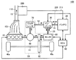
図1は、この発明による排気熱発電装置を備えた自動車のハイブリッドシステム100の全体構成を示すブロック図である。
FIG. 1 is a block diagram showing the overall configuration of a
図1を参照して、この発明の実施の形態によるハイブリッドシステム100は、エンジン10と、バッテリ20と、インバータ30と、車輪40aと、トランスアクスル50と、ECU(Electric Control Unit)90と、排気マニホールド105と、排気管110と、排気熱発電装置200とを備える。
Referring to FIG. 1,
エンジン10は、ガソリン等の燃料の燃焼エネルギを源として、車輪40aの駆動力を発生する。すなわち、エンジン10は、この発明における「第1の駆動力発生装置」に相当する。また、エンジン10は、この発明における「熱源」としても作用する。排気マニホールド105は、エンジン10からの排気15をまとめて排気管110へ送出する。排気管110は、排気15を所定方向に排出する。
The
バッテリ20は、「電力源」として動作して、電力ライン51に直流電力を供給する。バッテリ20は、充電可能な二次電池で構成され、代表的には、ニッケル・水素蓄電池やリチウムイオン二次電池等が適用される。
The
インバータ30は、電力ライン51にバッテリ20から供給された直流電力を交流電力に変換して、電力ライン53へ出力する。あるいは、インバータ30は、電力ライン52,53に供給された交流電力を直流電力に変換して、電力ライン51へ出力する。
The
トランスアクスル50は、トランスミッションとアクスル(車軸)を一体構造として備えており、動力分割機構60と、減速機62と、ジェネレータ70と、モータ80とを有する。
The
動力分割機構60は、エンジン10によって生じた駆動力を、減速機62を介して車輪40a駆動用の車軸41へ伝達する経路と、ジェネレータ70へ伝達する経路とに分割可能である。
The
ジェネレータ70は、動力分割機構60を介して伝達されたエンジン10からの駆動力によって回転されて発電する。ジェネレータ70による発電電力は、電力ライン52を介してインバータ30へ供給され、バッテリ20の充電電力として、あるいはモータ80の駆動電力として用いられる。すなわち、ジェネレータ70は、この発明における「発電装置」に相当する。
The
モータ80は、インバータ30から電力ライン53に供給された交流電力によって回転駆動される。すなわち、インバータ30は、この発明における「駆動電力変換装置」に対応する。
The
モータ80によって生じた駆動力は、減速機62を介して車軸41へ伝達される。すなわち、モータ80は、車輪駆動力を発生する「第2の駆動力発生装置」に相当する。
The driving force generated by the
また、回生制動動作時にモータ80が車輪40aの減速に伴って回転される場合には、モータ80に生じた起電力(交流電力)が、電力ライン53へ供給される。
Further, when the
ECU90は、ハイブリッドシステム100が搭載された自動車を運転者の指示に応じて運転させるために、自動車に搭載された機器・回路群の全体動作を制御する。ECU90は、代表的には、予めプログラムされた所定シーケンスおよび所定演算を実行するためのマイクロコンピュータ等で構成される。
The
このように、ハイブリッドシステム100を搭載したハイブリッド自動車においては、車輪40aは、エンジン10による駆動力およびモータ80による駆動力の両方によって駆動可能である。
Thus, in the hybrid vehicle equipped with the
排気熱発電装置200は、排気管110を介して取出された、エンジン10からの排気の熱エネルギを源として発電する。排気熱発電装置200の発電電力は、経路215に示すようにバッテリ20の充電に用いられ、あるいは、経路220に示すように直接インバータ30へ供給されて、最終的にはモータ80が発生する車輪駆動力の源の一部となる。
The exhaust
なお、図示しないが、バッテリ20の供給電力は、モータ80駆動用のインバータ30以外への機器および回路へも供給可能である。すなわち、排気熱発電装置200の発電電力は、バッテリ20の充電を介して、自動車に搭載された任意の機器および回路の駆動電力としても使用できる。あるいは、排気熱発電装置200の発電電力を図1に示す経路以外によって他の機器および回路へ直接供給する構成とすることも可能である。
Although not shown, the power supplied from the
また、排気熱発電装置200の構成については後ほど詳細に説明する。
The configuration of the exhaust
ハイブリッドシステム100では、発進時ならびに低速走行時あるいは緩やかな坂を下るとき等の軽負荷時には、エンジン効率の悪い領域を避けるために、エンジン10を動作させることなく、モータ80による駆動力で走行する。
The
通常走行時には、エンジン10から出力された駆動力は、動力分割機構60によって、車輪40aの駆動力と、ジェネレータ70での発電用駆動力とに分割される。ジェネレータ70による発電電力は、モータ80の駆動に用いられる。したがって、通常走行時には、エンジン10による駆動力をモータ80による駆動力でアシストして、車輪40aが駆動される。ECU90は、動力分割機構60による動力分割比率を全体の効率が最大となるように制御する。
During normal travel, the driving force output from the
全開加速時には、バッテリ20からの供給電力がモータ80の駆動にさらに用いられて、車輪40aの駆動力がさらに増加する。
During full open acceleration, the power supplied from the
減速および制動時には、モータ80は、車輪40aによって回転駆動されて発電機として作用する。モータ80の回生発電によって回収された電力は、電力ライン53、インバータ30および電力ライン51を介してバッテリ20の充電に用いられる。
During deceleration and braking, the
さらに、車両停止時には、エンジン10は自動的に停止される。
Further, when the vehicle is stopped, the
このように、この発明の実施の形態によるハイブリッドシステム100は、エンジンによって発生された駆動力と、電気エネルギを源としてモータ80によって発生された駆動力等の組合せによって、燃費を向上させた車両運転を行なう。
As described above, the
ECU90は、車両状況に応じてエンジン10およびモータ80の作動を制御する。特に、ECU90は、バッテリ20が一定の充電状態を維持する制御を行なっており、SOC(State of Charge)値の監視等によってバッテリ充電量の低下を検知すると、上記の基本的なエンジン10およびモータ80の作動条件に加えて、ジェネレータ70の駆動によってバッテリ20を充電するためにエンジン10を作動させる。
The
この発明による排気熱発電装置200によって排気15の熱エネルギから得られた電気エネルギは、バッテリ20の充電電力あるいはインバータ30への入力電力として、ハイブリッドシステム100中で回収される。したがって、排気熱発電装置200の熱電発電効率を改善することにより、ハイブリッドシステム100を搭載した自動車全体におけるエネルギ効率が向上する。
The electric energy obtained from the heat energy of the
この発明による排気熱発電装置200は、以下に説明するような構成とすることで、その熱電発電効率を改善する。
The exhaust
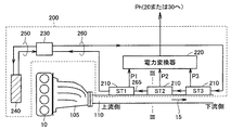
図2は、この発明の実施の形態による排気熱発電装置200の構成を示すブロック図である。
FIG. 2 is a block diagram showing a configuration of exhaust heat
図2を参照して、「熱源」であるエンジン10からの排気15は、排気マニホールド105で集められた後、排気管110により所定方向に沿って排出される。
Referring to FIG. 2,
排気熱発電装置200は、排気管110に取付けられた複数のスタック210と、電力変換器220と、冷却水ポンプ230と、冷却水ラジエータ240と、冷却水循環路250,260とを有する。
The exhaust
この発明における「冷媒供給部」に相当する冷却水ポンプ230は、冷却水循環路250,260のそれぞれに冷媒が循環するように、冷媒を供給する。冷媒としては代表的には水が用いられるので、以下では冷媒を「冷却水」と称する。冷却水循環路250,260内での冷却水の流れ方向は、図中では当該循環路上の矢印で示される。
The cooling
冷却水循環路260には、排気管110に沿って設けられ、内部を冷却水が流れる冷却水管265が含まれる。冷却水管265は、この発明における「冷却管」に相当する。
The cooling
複数のスタック210は、排気15の上流側から下流側に沿って順次設けられる。図2の構成例では、排気15の上流側から下流側へスタックST1,ST2,ST3が順に設けられる。各スタック210は同様の構造を有する。
The plurality of
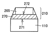
図3を参照して、各スタック210において、高温端271が排気管110と接し、かつ、低温端272が冷却水管265と接するように熱電発電素子270が取付けられる。これにより、複数の熱電発電素子270は、排気管110および冷却水管265に対して、排気15の上流側から下流側へ順次取付けられる。
Referring to FIG. 3, in each
熱電発電素子270は、高温端271および低温端272の間の温度差に応じた電力を発電する。したがって、排気管110の上流側から下流側へ順次取付けられた熱電発電素子270の各々は、対応の部位の排気管110および冷却水管265の温度差に応じた電力を発電する。
The thermoelectric
なお、図3に示すように、熱電発電素子270を排気管110および冷却水管265の間に挟み込んで配置することにより、熱電発電素子270を効率的に取付けることができる。
As shown in FIG. 3, the thermoelectric
再び図2を参照して、スタックST1〜ST3の熱電発電素子270による発電電力P1〜P3は、電力変換器220によって電力Phに変換される。電力Phは、図1に示したように、バッテリ20の充電電力に用いられ、あるいは、インバータ30へ直接入力される。すなわち、電力変換器220は、スタックST1〜ST3からの発電電力P1〜P3を、バッテリ20の充電電力あるいはインバータ30への入力電力へ変換する。
Referring again to FIG. 2, the electric power P1 to P3 generated by the thermoelectric
冷却水は、主に冷却水管265の通過時に排気管を冷却することにより、排気15から熱を奪ってその温度を下げる。
The cooling water cools the exhaust pipe mainly when it passes through the cooling
冷却水循環路260を循環して温度が情報した冷却水は、冷却水循環路250へ送出され冷却水ラジエータ240によって放熱される。冷却水循環路260を循環した冷却水は、再び冷却水循環路250へ送出されて排気15の冷却に用いられる。
The cooling water whose temperature has been circulated through the cooling
この発明による排気熱発電装置200では、冷却水管265中の冷却水の流れが、排気管110を流れる排気15の方向と対向するように設計される。
In the exhaust
具体的には、冷却水ポンプ230から送出された冷却水が、排気管110の下流側のスタックST3から上流側のスタックST1の方向へ、スタックST3〜ST2〜ST1の順に冷却水管265中を通過するように冷却水循環路260が設計される。
Specifically, the cooling water delivered from the cooling
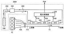
図4には、比較例として示される、冷却水の循環経路が異なる排気熱発電装置200♯が示される。
FIG. 4 shows an exhaust thermal
図4を参照して、比較例として示される排気熱発電装置200♯は、排気管110中の排気15と同じ方向に、冷却水管265を冷却水を流れる点が図2に示した排気熱発電装置200と異なる。排気熱発電装置200♯のその他の構成は、図2に示した排気熱発電装置200と同様である。
Referring to FIG. 4, an exhaust
すなわち、排気熱発電装置200♯では、排気15の上流側のスタックST1から下流側のスタックST3へ向かってスタックST1〜ST2〜ST3の順に、冷却水が冷却水管265中を通過するように冷却水ポンプ230が配置される。
That is, in exhaust
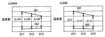
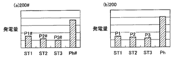
図5(a)には、排気熱発電装置200♯での各スタックST1〜ST3における熱電発電素子の高温端および低温端の間の温度差が示され、図6(a)には図5(a)に示した温度差による各スタックでの発電量が示される。
FIG. 5A shows the temperature difference between the high temperature end and the low temperature end of the thermoelectric power generation elements in each of the stacks ST1 to ST3 in the exhaust
排気熱発電装置200♯では、排気管110での排気15の流れ方向と、冷却水管265中の冷却水の流れ方向とが同じであるので、冷却水管265と接する低温端272の温度282は、スタックST1からST3へ向かって順に高くなる。一方、排気管110と接する低温端272の温度282は、スタックST1からST3へ向かって順に低くなる。
In exhaust
この結果、高温端および低温端の温度281および282の温度差Δt1♯,Δt2♯、Δt3♯のばらつきが大きくなる。すなわち、排気管の下流側に位置するスタック(ST3)において、温度差Δt3♯を確保することが困難となる。
As a result, variations in the temperature differences Δt1 #, Δt2 #, Δt3 # between the
これに対して、図5(b)には、この発明による排気熱発電装置200での各スタックST1〜ST3における熱電発電素子の高温端および低温端の間の温度差が示され、図6(b)には図5(b)に示した温度差による各スタックでの発電量が示される。
On the other hand, FIG. 5B shows a temperature difference between the high temperature end and the low temperature end of the thermoelectric power generation element in each of the stacks ST1 to ST3 in the exhaust
排気熱発電装置200では、排気管110内の排気15の流れ方向と、冷却水管265内の冷却水の流れ方向とが対向するため、冷却水管265と接する低温端272の温度282は、スタックST1からST3へ向かって順に低くなる。排気管110と接する低温端272の温度282は、排気熱発電装置200♯と同様に、スタックST1からST3に向かって順に低くなる。
In the exhaust
したがって、高温端および低温端の温度281および282の温度差Δt1,Δt2,Δt3のばらつきは抑制され、排気管110の下流側に位置するスタック(ST3)においても温度差Δt3を確保することが可能となる。
Therefore, variations in the temperature differences Δt1, Δt2, Δt3 between the
この結果、図6(a)に示されるように、比較例として示される排気熱発電装置200♯では、スタックST1〜ST3における発電量P1♯〜P3♯にばらつきが大きいため、特に下流側のスタックST3♯での発電量を確保することができず、発電量Ph♯についてもそれほど大きく確保できない。
As a result, as shown in FIG. 6 (a), in the exhaust heat
これに対して、図6(b)に示されるように、この発明による排気熱発電装置200では、下流側のスタックST3でも熱電発電素子での温度差Δt3を確保できるので、各スタックST1〜ST3における発電量P1〜P3のばらつきが小さくなり、トータルの発電量Phを比較例でのPh♯よりも大きくすることができる。これにより、排気熱発電装置の発電効率が向上する。
On the other hand, as shown in FIG. 6B, in the exhaust
さらに、発電効率に優れたこの発明による排気熱発電装置によって、以下に説明するようなエンジン駆動制御を行なうことにより、ハイブリッド自動車の燃費を低減できる。 Further, by performing the engine drive control as described below with the exhaust heat power generator according to the present invention having excellent power generation efficiency, the fuel efficiency of the hybrid vehicle can be reduced.
図1で説明したように、ECU90は、車両状況に応じてエンジン10およびモータ80の作動を制御する。特に、SOC(State of Charge)値の監視等によって、バッテリ20の充電状態を一定レベルへ維持するために、ECU90は、エンジン10に要求されるエンジンパワーPeを算出するとともに、算出されたエンジンパワーPeに基づいて、下記の式(1),(2)に従ってエンジン10の作動・停止および作動時の出力パワーを制御する。
As described with reference to FIG. 1, the
Pe=Pv+Pb ・・・(1)
Pb=Pchg+Psm−Ph ・・・(2)
式(1),(2)において、車両要求パワーPvは、アクセル操作に代表される運転者からの操作および、現在の車速に代表される車両状況等から、ECU90に予めプログラムされた所定の算出式に従って算出されるものとする。バッテリパワーPbは、SOC値に応じて算出されるバッテリ充電要求パワーPchg、および補機等での損失パワーPsmの和から、排気熱発電装置200による発電量Phを差し引いて算出される。
Pe = Pv + Pb (1)
Pb = Pchg + Psm−Ph (2)
In the formulas (1) and (2), the vehicle required power Pv is a predetermined calculation programmed in advance in the
このように、車両要求パワーPvおよびバッテリ20の充電状態を維持するためのバッテリ充電要求パワーPchgを考慮してエンジン10の作動・停止を制御する構成において、排気熱発電装置による発電量Phをさらに反映して当該制御を行なうことにより、排気熱発電装置での発電効率向上をより有効にエンジン10の作動頻度低減につなげることができる。これにより、排気熱発電装置200での発電効率向上を自動車の燃費向上へより直接的に反映することが可能となる。
As described above, in the configuration in which the operation / stop of the
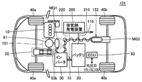
なお、この発明による排気熱発電装置200は、図1に示したハイブリッドシステムのみでなく、たとえば図7に示すような、四輪駆動が可能なハイブリッドシステム101に適用することも可能である。
The exhaust
図7は、この発明による排気熱発電装置を備えた自動車のハイブリッドシステムの他の構成例を示すブロック図である。 FIG. 7 is a block diagram showing another configuration example of an automobile hybrid system equipped with an exhaust heat power generator according to the present invention.
図7を参照して、この発明の他の例によるハイブリッドシステム101は、前輪40aおよび40bを駆動可能な四輪駆動システムを有している。
Referring to FIG. 7,
ハイブリッドシステム101は、エンジン10と、バッテリ20と、インバータ30と、ECU90と、フロント用のトランスアクスル151と、リア用のトランスアクスル152と、排気熱発電装置200とを有する。
The
フロント用のトランスアクスル151は、動力分割機構61と、モータジェネレータMG1と、無段変速装置(CVT)55とを有する。モータジェネレータMG1は、車輪40aの駆動用に設けられた図1におけるモータ80と同様の機能を有する。動力分割機構61は、図1における動力分割機構60と同様の機能を有し、エンジン10からの動力を、無段変速機55を介して車輪40aの駆動力とする経路と、モータジェネレータMG1の発電用駆動力する経路との間で分配する。
The
さらに、モータジェネレータMG1がインバータ30からの供給電力によって回転されることで発生する駆動力は、動力分割機構60を介して無段変速機55へ与えられることにより、車輪40aの駆動力として用いることができる。
Furthermore, the driving force generated when motor generator MG1 is rotated by the power supplied from
リア用のトランスアクスル152は、モータジェネレータMG2を有する。モータジェネレータMG2は、インバータ30からの供給電力によって後輪40bを駆動することができる。
図1に示した構成と同様に、バッテリ20からの供給電力は電力ライン51を介してインバータ30へ供給される。また、排気熱発電装置200からの発電電力は、経路215によってバッテリ20を充電するために用いてもよく、あるいは経路220に示すようにインバータ30へ直接入力することも可能である。
Similar to the configuration shown in FIG. 1, the power supplied from the
モータジェネレータMG1およびMG2は、回生動作時には車輪40a,40bによって回転されて発電する。発電された電力は、インバータ30によって直流電力に変換されてバッテリ20の充電に用いられる。
Motor generators MG1 and MG2 generate power by being rotated by
ハイブリッドシステム101では、発進時は、モータジェネレータMG1,MG2によって車輪40a,40bが駆動される。また、エンジン効率の悪い領域での走行となる軽負荷時には、エンジン10を停止して、フロント用のモータジェネレータMG1による前輪40aの駆動によって走行が行なわれる。
In
通常走行時には、エンジン効率の良い領域での走行となるため、基本的にはエンジン10の動力によって前輪40aを駆動することで走行する。この際に、バッテリ20の充電量が不足している場合には、必要に応じてエンジン10の駆動力を用いてモータジェネレータMG1を発電機として駆動することによって、バッテリ20の充電が行なわれる。
During normal traveling, the vehicle travels in a region where engine efficiency is good. Therefore, the vehicle basically travels by driving the
全開加速時には、エンジン10の出力が上昇されるとともに、無段変速機(CVT)の変速比を大きくすることにより加速が行なわれる。また、モータジェネレータMG1によって車輪駆動力をアシストすることで加速力が増加される。さらに、必要に応じてリア用のモータジェネレータMG2による後輪40bの駆動によってさらに加速が強化される。
During full-open acceleration, the output of the
制動減速時には、モータジェネレータMG1,MG2を発電機として作動させて運動エネルギを回収し、バッテリ20を充電する。
At the time of braking deceleration, motor generators MG1 and MG2 are operated as generators to recover kinetic energy and
さらに低摩擦係数(μ)路走行時には、前輪40aのスリップ検出等に応答して、フロント用のモータジェネレータMG1を発電機として作動させて発電した電力を利用して、リア用のモータジェネレータMG2を駆動して四輪駆動(4WD)とすることにより車両の走行安定性を確保する。
Further, when traveling on a road with a low friction coefficient (μ), the rear motor generator MG2 is operated by using the electric power generated by operating the front motor generator MG1 as a generator in response to the slip detection of the
この際に、モータジェネレータMG1の発電量ではモータジェネレータMG2の駆動電力が十分供給できない場合には、バッテリ20からの供給電力によってモータジェネレータMG2が動作される。
At this time, if the drive power of motor generator MG2 cannot be sufficiently supplied by the power generation amount of motor generator MG1, motor generator MG2 is operated by the power supplied from
ハイブリッドシステム101においても、ECU90は、車両状況に応じた車両要求パワーおよびバッテリ20の充電状態を維持するように算出されるバッテリパワーに基づいて、エンジン10の作動・停止および出力パワーを制御するので、この発明による効率の高い排気熱発電装置を用いることにより、エンジンの作動頻度および出力パワーを有効に低減して燃費向上を図ることが可能となる。
Also in the
以上この発明の実施の形態では、この発明による排気熱発電装置をハイブリッド自動車に搭載する例について説明した。しかしながら、この発明の適用は上記の実施の形態に限定されるものではない。すなわち、この発明による排気熱発電装置は、この他のあらゆる構成のハイブリッド自動車に搭載して、エンジン排気熱を電気エネルギとして有効に回収して燃費向上を実現できる。また、この発明による排気熱発電装置の適用は、ハイブリッド自動車に限定されず、熱源からの排気を所定方向に導く排気管と当該排気管と並行に設けられた冷却水管とを設ける系に共通に適用して、熱回収効率を向上させることが可能である。 In the above embodiments of the present invention, the example in which the exhaust heat power generator according to the present invention is mounted on a hybrid vehicle has been described. However, the application of the present invention is not limited to the above embodiment. That is, the exhaust heat power generator according to the present invention can be mounted on a hybrid vehicle having any other configuration, and the exhaust heat of the engine can be effectively recovered as electric energy to improve fuel efficiency. The application of the exhaust thermoelectric generator according to the present invention is not limited to a hybrid vehicle, but is commonly applied to a system in which an exhaust pipe that guides exhaust from a heat source in a predetermined direction and a cooling water pipe provided in parallel with the exhaust pipe. It can be applied to improve the heat recovery efficiency.
今回開示された実施の形態はすべての点で例示であって制限的なものではないと考えられるべきである。本発明の範囲は上記した説明ではなくて特許請求の範囲によって示され、特許請求の範囲と均等の意味および範囲内でのすべての変更が含まれることが意図される。 The embodiment disclosed this time should be considered as illustrative in all points and not restrictive. The scope of the present invention is defined by the terms of the claims, rather than the description above, and is intended to include any modifications within the scope and meaning equivalent to the terms of the claims.
10 エンジン、15 排気、20 バッテリ、30 インバータ、40a 車輪(前輪)、40b 後輪、41 車軸、50,151,152 トランスアクスル、51〜53 電力ライン、55 無段変速機(CVT)、60,61 動力分割機構、62 減速機、70 ジェネレータ、80 モータ、100,101 ハイブリッドシステム、105 排気マニホールド、110 排気管、200 排気熱発電装置、210,ST1,ST2,ST3 スタック、220 電力変換器、230 冷却水ポンプ、240 冷却水ラジエータ、250,260 冷却水循環路、265 冷却水管、270 熱電発電素子、271 高温端、272 低温端、281 高温端温度、282 低温端温度、MG1,MG2 モータジェネレータ、Pb バッテリパワー、Pchg バッテリ充電要求パワー、Pe エンジンパワー、Ph 発電量(排気熱発電装置)、Psm 損失パワー、Pv 車両要求パワー。 10 engine, 15 exhaust, 20 battery, 30 inverter, 40a wheel (front wheel), 40b rear wheel, 41 axle, 50, 151, 152 transaxle, 51-53 power line, 55 continuously variable transmission (CVT), 60, 61 Power split mechanism, 62 Reducer, 70 Generator, 80 Motor, 100, 101 Hybrid system, 105 Exhaust manifold, 110 Exhaust pipe, 200 Exhaust thermoelectric generator, 210, ST1, ST2, ST3 Stack, 220 Power converter, 230 Cooling water pump, 240 Cooling water radiator, 250, 260 Cooling water circulation path, 265 Cooling water pipe, 270 Thermoelectric power generation element, 271 High temperature end, 272 Low temperature end, 281 High temperature end temperature, 282 Low temperature end temperature, MG1, MG2 Motor generator, Pb Battery power , Pchg battery charge power demand, Pe engine power, Ph power generation amount (exhaust heat recovery power generation device), Psm loss power, Pv vehicle power demand.
Claims (6)
前記排気管に沿って設けられ、前記排気管を冷却するための冷媒が内部を流れる冷却管と、
前記冷却管へ前記冷媒を供給する冷媒供給部と、
前記排気の流れる方向に沿って前記排気管および前記冷却管に順次取付けられた複数の熱電発電素子とを備え、
前記複数の熱電発電素子の各々は、高温端および低温端の間の温度差に応じた電力を発電し、かつ、各前記熱電発電素子の高温端および低温端は、対応の部位の前記排気管および前記冷却管にそれぞれ取付けられ、
前記冷媒供給部は、前記排気管内を前記排気が流れる方向と対向する方向に前記冷媒が前記冷却管内を流れるように、前記冷媒を供給する、排気熱発電装置。 An exhaust pipe through which exhaust from the heat source flows in a predetermined direction;
A cooling pipe which is provided along the exhaust pipe and in which a refrigerant for cooling the exhaust pipe flows;
A refrigerant supply unit for supplying the refrigerant to the cooling pipe;
A plurality of thermoelectric generators sequentially attached to the exhaust pipe and the cooling pipe along the flow direction of the exhaust,
Each of the plurality of thermoelectric power generation elements generates electric power according to a temperature difference between a high temperature end and a low temperature end, and the high temperature end and the low temperature end of each thermoelectric generation element correspond to the exhaust pipe of the corresponding part. And are respectively attached to the cooling pipes,
The exhaust gas thermoelectric generator, wherein the refrigerant supply unit supplies the refrigerant so that the refrigerant flows in the cooling pipe in a direction opposite to a direction in which the exhaust flows in the exhaust pipe.
請求項1または2に記載の排気熱発電装置と、
電力源とを備え、
前記排気熱発電装置は、前記第1の駆動力発生装置を前記熱源として電力を発電し、
前記排気熱発電装置による発電電力および前記電力源からの供給電力を源として車輪駆動力を発生する第2の駆動力発生装置をさらに備える、自動車。 A first driving force generator for generating wheel driving force using fuel combustion energy as a source;
The exhaust heat power generator according to claim 1 or 2,
With a power source,
The exhaust heat power generator generates power using the first driving force generator as the heat source,
An automobile further comprising a second driving force generation device that generates wheel driving force using power generated by the exhaust heat power generation device and power supplied from the power source as sources.
前記排気熱発電装置は、前記排気熱発電装置による発電電力を前記二次電圧の充電電圧に変換する電力変換器をさらに含む、請求項3に記載の自動車。 The power source is a secondary battery;
The automobile according to claim 3, wherein the exhaust thermoelectric generator further includes a power converter that converts electric power generated by the exhaust thermoelectric generator into a charging voltage of the secondary voltage.
前記排気熱発電装置は、前記排気熱発電装置による発電電力を前駆動電力変換への入力電力へ変換する電力変換器をさらに含む、請求項3に記載の自動車。 A drive power converter that converts the input power into the drive power of the second drive force generator;
The automobile according to claim 3, wherein the exhaust heat power generator further includes a power converter that converts electric power generated by the exhaust heat power generator into input power for pre-drive power conversion.
前記自動車を運転者の指示に応じて運転させるための制御装置とをさらに備え、
前記電力源は二次電池であり、
前記制御装置は、前記運転者の指示に基づいて算出される車両の走行に必要な車両要求パワーおよび前記二次電池の充電レベルを維持するための充電要求パワーに加えて、前記排気熱発電装置による発電電力をさらに考慮して、前記第1の駆動力発生装置の作動を制御する、請求項3に記載の自動車。 A power generation device that converts at least a part of the wheel driving force generated by the first driving force generation device into electric power that can be used for driving power of the second driving force generation device;
A control device for driving the vehicle in accordance with a driver's instruction;
The power source is a secondary battery;
In addition to the required vehicle power required for traveling the vehicle and the required charging power for maintaining the charging level of the secondary battery calculated based on the driver's instruction, the control device includes the exhaust thermoelectric generator The automobile according to claim 3, wherein the operation of the first driving force generator is controlled in consideration of electric power generated by the vehicle.
Priority Applications (6)
| Application Number | Priority Date | Filing Date | Title |
|---|---|---|---|
| JP2004113361A JP2005299417A (en) | 2004-04-07 | 2004-04-07 | Exhaust heat generator and automobile equipped with the same |
| PCT/JP2005/004383 WO2005098225A1 (en) | 2004-04-07 | 2005-03-07 | Exhaust heat recovery power generation device and automobile equipped therewith |
| KR1020067023294A KR20060133093A (en) | 2004-04-07 | 2005-03-07 | Exhaust Heat Recovery System and Automobile |
| CNA2005800121185A CN1946927A (en) | 2004-04-07 | 2005-03-07 | Exhaust heat recovery power generation device and automobile equipped therewith |
| EP05720654A EP1740818A1 (en) | 2004-04-07 | 2005-03-07 | Exhaust heat recovery power generation device and automobile equipped therewith |
| US10/591,858 US20070193617A1 (en) | 2004-04-07 | 2005-03-07 | Exhaust heat recovery power generation device and automobile equipped therewith |
Applications Claiming Priority (1)
| Application Number | Priority Date | Filing Date | Title |
|---|---|---|---|
| JP2004113361A JP2005299417A (en) | 2004-04-07 | 2004-04-07 | Exhaust heat generator and automobile equipped with the same |
Publications (1)
| Publication Number | Publication Date |
|---|---|
| JP2005299417A true JP2005299417A (en) | 2005-10-27 |
Family
ID=34961506
Family Applications (1)
| Application Number | Title | Priority Date | Filing Date |
|---|---|---|---|
| JP2004113361A Pending JP2005299417A (en) | 2004-04-07 | 2004-04-07 | Exhaust heat generator and automobile equipped with the same |
Country Status (6)
| Country | Link |
|---|---|
| US (1) | US20070193617A1 (en) |
| EP (1) | EP1740818A1 (en) |
| JP (1) | JP2005299417A (en) |
| KR (1) | KR20060133093A (en) |
| CN (1) | CN1946927A (en) |
| WO (1) | WO2005098225A1 (en) |
Cited By (12)
| Publication number | Priority date | Publication date | Assignee | Title |
|---|---|---|---|---|
| JP2008069771A (en) * | 2006-09-13 | 2008-03-27 | Caterpillar Inc | Thermoelectric system |
| JP2009299532A (en) * | 2008-06-11 | 2009-12-24 | Honda Motor Co Ltd | Co-generation apparatus |
| JP2011093528A (en) * | 2010-12-16 | 2011-05-12 | Bsst Llc | Energy management system for hybrid electric automobile |
| JP2011521139A (en) * | 2008-05-15 | 2011-07-21 | バイエリッシェ モートーレン ウエルケ アクチエンゲゼルシャフト | Cooling system for thermoelectric generator (TEG) |
| JP2013027312A (en) * | 2011-07-25 | 2013-02-04 | Boeing Co:The | Thermoelectric power generation from power feeder |
| JP2014181575A (en) * | 2013-03-18 | 2014-09-29 | Toho Gas Co Ltd | Cogeneration device |
| JP2014195359A (en) * | 2013-03-28 | 2014-10-09 | National Maritime Research Institute | Marine thermoelectric power generation system and ship |
| CN105281607A (en) * | 2015-11-16 | 2016-01-27 | 滨州学院 | Hot waste water generator |
| US9293680B2 (en) | 2011-06-06 | 2016-03-22 | Gentherm Incorporated | Cartridge-based thermoelectric systems |
| US9306143B2 (en) | 2012-08-01 | 2016-04-05 | Gentherm Incorporated | High efficiency thermoelectric generation |
| US9574517B2 (en) | 2013-11-12 | 2017-02-21 | Hyundai America Technical Center, Inc | Thermoelectric generator insert for engine waste heat recovery |
| JP2017118819A (en) * | 2017-03-16 | 2017-06-29 | 国立研究開発法人 海上・港湾・航空技術研究所 | Marine thermoelectric power generation system and ship |
Families Citing this family (62)
| Publication number | Priority date | Publication date | Assignee | Title |
|---|---|---|---|---|
| US7942010B2 (en) | 2001-02-09 | 2011-05-17 | Bsst, Llc | Thermoelectric power generating systems utilizing segmented thermoelectric elements |
| US7380586B2 (en) * | 2004-05-10 | 2008-06-03 | Bsst Llc | Climate control system for hybrid vehicles using thermoelectric devices |
| US9006556B2 (en) * | 2005-06-28 | 2015-04-14 | Genthem Incorporated | Thermoelectric power generator for variable thermal power source |
| US7779639B2 (en) | 2006-08-02 | 2010-08-24 | Bsst Llc | HVAC system for hybrid vehicles using thermoelectric devices |
| US20100155018A1 (en) | 2008-12-19 | 2010-06-24 | Lakhi Nandlal Goenka | Hvac system for a hybrid vehicle |
| US7426910B2 (en) | 2006-10-30 | 2008-09-23 | Ford Global Technologies, Llc | Engine system having improved efficiency |
| EP2167887B1 (en) | 2007-05-25 | 2021-01-13 | Gentherm Incorporated | System and method for distributed thermoelectric heating and cooling |
| DE102008006705A1 (en) * | 2008-01-30 | 2009-08-06 | Robert Bosch Gmbh | Power supply means |
| DE102008023831A1 (en) * | 2008-05-15 | 2009-11-19 | Bayerische Motoren Werke Aktiengesellschaft | Exhaust system for an internal combustion engine |
| WO2009149207A2 (en) | 2008-06-03 | 2009-12-10 | Bsst Llc | Thermoelectric heat pump |
| US8793992B2 (en) * | 2008-07-28 | 2014-08-05 | Spansion Llc | Thermoelectric device for use with Stirling engine |
| DE102008063487A1 (en) * | 2008-12-17 | 2010-06-24 | Emitec Gesellschaft Für Emissionstechnologie Mbh | Device for generating electrical energy from an exhaust gas |
| US8013458B2 (en) * | 2009-01-16 | 2011-09-06 | Nissan North America, Inc. | Vehicle heat exchanger arrangement |
| DE102009000973A1 (en) * | 2009-02-18 | 2010-08-19 | Zf Friedrichshafen Ag | Operation of vehicle hybrid drive train in automobile, ship or locomotive, employs strategy dependent on electrical energy converted from heat, by thermo-electric generator |
| US20110308560A1 (en) * | 2009-02-26 | 2011-12-22 | Ivan Arbuckle | Temperature and flow control of exhaust gas for thermoelectric units |
| US20120060775A1 (en) * | 2009-03-31 | 2012-03-15 | Renault Trucks | Energy recovery system for an internal combustion engine arrangement, comprising thermoelectric devices |
| WO2010135363A2 (en) | 2009-05-18 | 2010-11-25 | Bsst Llc | Temperature control system with thermoelectric device |
| CN101958670B (en) | 2009-07-15 | 2014-08-13 | 鸿富锦精密工业(深圳)有限公司 | Waste heat recovering system |
| CN102549789B (en) * | 2009-07-24 | 2015-03-18 | Bsst有限责任公司 | Thermoelectric-based power generation systems and methods |
| CN101956594B (en) * | 2010-08-27 | 2012-06-27 | 奇瑞汽车股份有限公司 | Engine waste gas energy utilization device and automobile using same |
| KR101707816B1 (en) * | 2010-10-26 | 2017-02-20 | 에스케이이노베이션 주식회사 | Thermoelectric Generation Vehicle, TEGV |
| JP6141195B2 (en) * | 2011-01-20 | 2017-06-07 | サウジ アラビアン オイル カンパニー | Membrane separation method and system using waste heat for in-vehicle recovery and storage of CO2 from exhaust gas of vehicle internal combustion engine |
| JP5596576B2 (en) * | 2011-01-21 | 2014-09-24 | トヨタ自動車株式会社 | Thermoelectric device |
| JP5745877B2 (en) * | 2011-02-03 | 2015-07-08 | トヨタ自動車株式会社 | Vehicle equipment mounting structure |
| CN102650555A (en) * | 2011-02-25 | 2012-08-29 | 中国科学院理化技术研究所 | Heating pipe network calorimeter based on thermoelectricity and turbine power generation |
| FR2973301B1 (en) * | 2011-03-29 | 2013-05-10 | Renault Sa | ENERGY COGENERATION SYSTEM FOR ELECTRIC MOTOR VEHICLE |
| US9006557B2 (en) | 2011-06-06 | 2015-04-14 | Gentherm Incorporated | Systems and methods for reducing current and increasing voltage in thermoelectric systems |
| CN102281025B (en) * | 2011-08-08 | 2013-10-16 | 武汉理工大学 | Thermoelectric conversion automotive power supply system using waste heat from automobile exhaust and control method thereof |
| CN102427319B (en) * | 2011-12-13 | 2014-06-11 | 武汉理工大学 | Single-module independent water-cooled type automobile tail gas thermoelectric conversion device and method |
| RU2499902C2 (en) * | 2011-12-19 | 2013-11-27 | Федеральное государственное бюджетное образовательное учреждение высшего профессионального образования "Юго-Западный государственный университет" (ЮЗГУ) | Vehicle power plant |
| EP2639437A1 (en) * | 2012-03-16 | 2013-09-18 | Perkins Engines Company Limited | Control system for an engine assembly |
| CN102815192B (en) * | 2012-08-09 | 2015-09-02 | 武汉理工大学 | Based on mild hybrid power system and the control method of the conversion of vehicle exhaust thermoelectricity |
| KR101390688B1 (en) * | 2012-10-25 | 2014-04-30 | 현대자동차주식회사 | Thermoelectric generator for vehicle |
| GB2515446A (en) * | 2013-01-25 | 2014-12-31 | Europ Thermodynamics Ltd | Thermoelectric generators |
| US9065013B2 (en) * | 2013-10-10 | 2015-06-23 | Electro-Motive Diesel, Inc. | System and method for energy recovery |
| US20180090660A1 (en) | 2013-12-06 | 2018-03-29 | Sridhar Kasichainula | Flexible thin-film based thermoelectric device with sputter deposited layer of n-type and p-type thermoelectric legs |
| US10367131B2 (en) | 2013-12-06 | 2019-07-30 | Sridhar Kasichainula | Extended area of sputter deposited n-type and p-type thermoelectric legs in a flexible thin-film based thermoelectric device |
| US10290794B2 (en) | 2016-12-05 | 2019-05-14 | Sridhar Kasichainula | Pin coupling based thermoelectric device |
| US10141492B2 (en) | 2015-05-14 | 2018-11-27 | Nimbus Materials Inc. | Energy harvesting for wearable technology through a thin flexible thermoelectric device |
| US10566515B2 (en) | 2013-12-06 | 2020-02-18 | Sridhar Kasichainula | Extended area of sputter deposited N-type and P-type thermoelectric legs in a flexible thin-film based thermoelectric device |
| US11024789B2 (en) | 2013-12-06 | 2021-06-01 | Sridhar Kasichainula | Flexible encapsulation of a flexible thin-film based thermoelectric device with sputter deposited layer of N-type and P-type thermoelectric legs |
| JP2016003603A (en) * | 2014-06-16 | 2016-01-12 | トヨタ自動車株式会社 | vehicle |
| CN104124901A (en) * | 2014-08-04 | 2014-10-29 | 陈庆 | Automobile temperature difference power generation system |
| CN104279078B (en) * | 2014-09-26 | 2015-12-16 | 东风商用车有限公司 | Automobile exhaust thermoelectric power generation system |
| CN104279077B (en) * | 2014-09-26 | 2017-02-15 | 东风商用车有限公司 | Two-stage linkage type automobile exhaust temperature difference power generation system |
| US11283000B2 (en) | 2015-05-14 | 2022-03-22 | Nimbus Materials Inc. | Method of producing a flexible thermoelectric device to harvest energy for wearable applications |
| US11276810B2 (en) | 2015-05-14 | 2022-03-15 | Nimbus Materials Inc. | Method of producing a flexible thermoelectric device to harvest energy for wearable applications |
| CN105048871A (en) * | 2015-05-22 | 2015-11-11 | 武汉理工大学 | Thermoelectric power generation system employing high-temperature exhaust gas |
| CN105262373A (en) * | 2015-10-10 | 2016-01-20 | 汤瑞祥 | Solar water heater power generation device |
| CN105703662A (en) * | 2015-12-24 | 2016-06-22 | 芜湖恒耀汽车零部件有限公司 | Automobile tail gas thermoelectric power generation system |
| CN106703954A (en) * | 2016-12-25 | 2017-05-24 | 常州创索新材料科技有限公司 | Device for generating power by utilizing automobile tail gas temperature difference |
| CN107013364B (en) * | 2017-04-28 | 2023-03-10 | 西安工程大学 | An engine cooling cycle waste heat power generation system |
| CN107040168B (en) * | 2017-05-22 | 2019-03-19 | 武汉理工大学 | A heat exchange device for generating electricity by utilizing the temperature difference of exhaust gas |
| CN107458201A (en) * | 2017-06-22 | 2017-12-12 | 江苏银基烯碳能源科技有限公司 | A kind of driving motor of electric vehicle cooling system |
| US10428713B2 (en) | 2017-09-07 | 2019-10-01 | Denso International America, Inc. | Systems and methods for exhaust heat recovery and heat storage |
| CN108223086B (en) * | 2017-12-20 | 2020-06-09 | 江苏大学 | A heating system for SCR urea supply pipeline using vehicle exhaust air temperature difference to generate electricity |
| FR3085086B1 (en) * | 2018-08-14 | 2020-08-21 | Psa Automobiles Sa | THERMOELECTRIC MACHINE ESPECIALLY FOR HYBRID ELECTRIC VEHICLES WITH EXTENDED AUTONOMY |
| CN110067623A (en) * | 2019-03-26 | 2019-07-30 | 深圳市德卡尔科技有限公司 | Parking heater assembly, automobile parking heating system and control method |
| US20220384702A1 (en) * | 2021-05-26 | 2022-12-01 | Austin Geotech Services, Inc. | Efficient integration of thermoelectric devices into heat exchange surfaces for power generation |
| CN114654995B (en) * | 2022-03-21 | 2025-05-09 | 中国科学技术大学 | A hybrid refrigerated truck configuration coupled with a combined cooling and power waste heat recovery system |
| CN114776432B (en) * | 2022-04-14 | 2024-02-06 | 江铃汽车股份有限公司 | Waste heat recovery control system |
| WO2025166090A1 (en) * | 2024-01-31 | 2025-08-07 | Cummins Inc. | Waste heat recovery system for hydrogen internal combustion engines |
Family Cites Families (24)
| Publication number | Priority date | Publication date | Assignee | Title |
|---|---|---|---|---|
| US1118269A (en) * | 1906-01-10 | 1914-11-24 | John L Creveling | Means for utilizing waste energy. |
| US1469264A (en) * | 1918-12-28 | 1923-10-02 | Lubeck Hilding | Regenerative braking system for electrically-driven vehicles |
| US2078362A (en) * | 1929-12-17 | 1937-04-27 | Arendt Morton | Gas electric vehicle |
| FR2512499A1 (en) * | 1981-09-04 | 1983-03-11 | Carabetian Charles | IC engine exhaust converter for heat to electricity - contains thermoelectric generators mounted between exhaust pipe and water cooled surface |
| JPS61254082A (en) | 1985-04-30 | 1986-11-11 | Suzuki Motor Co Ltd | Power generator utilizing exhaust heat |
| JPS63302119A (en) * | 1987-05-30 | 1988-12-09 | Isuzu Motors Ltd | Exhaust energy recovering engine |
| JPH05111101A (en) * | 1991-10-17 | 1993-04-30 | Hino Motors Ltd | Brake and auxiliary driver for vehicle |
| US5327987A (en) * | 1992-04-02 | 1994-07-12 | Abdelmalek Fawzy T | High efficiency hybrid car with gasoline engine, and electric battery powered motor |
| DE4217668C1 (en) * | 1992-05-28 | 1993-05-06 | Daimler Benz Ag | Method for controlling a hybrid drive that drives a vehicle |
| US5343970A (en) * | 1992-09-21 | 1994-09-06 | Severinsky Alex J | Hybrid electric vehicle |
| JPH10227238A (en) * | 1997-02-13 | 1998-08-25 | Nissan Motor Co Ltd | Vehicle electric energy supply device |
| SE512597C2 (en) * | 1997-06-02 | 2000-04-10 | Volvo Ab | Drive system for a vehicle |
| EP1055545B1 (en) * | 1999-05-26 | 2004-01-28 | Toyota Jidosha Kabushiki Kaisha | Hybrid vehicle with fuel cells incorporated therein and method of controlling the same |
| JP2001012240A (en) | 1999-06-23 | 2001-01-16 | Nissan Motor Co Ltd | Automotive waste heat power generator |
| JP3864625B2 (en) | 1999-07-12 | 2007-01-10 | トヨタ自動車株式会社 | Driving device for moving body |
| JP3584809B2 (en) * | 1999-10-08 | 2004-11-04 | トヨタ自動車株式会社 | Hybrid vehicle control device |
| US6724100B1 (en) * | 2000-09-08 | 2004-04-20 | Ford Motor Company | HEV charger/generator unit |
| US6450283B1 (en) * | 2000-11-27 | 2002-09-17 | Michael Blake Taggett | Waste heat conversion system |
| EP1226995A1 (en) * | 2001-01-27 | 2002-07-31 | Ford Global Technologies, Inc., A subsidiary of Ford Motor Company | Thermoelectric generator for a vehicle |
| US6539725B2 (en) * | 2001-02-09 | 2003-04-01 | Bsst Llc | Efficiency thermoelectrics utilizing thermal isolation |
| US7942010B2 (en) * | 2001-02-09 | 2011-05-17 | Bsst, Llc | Thermoelectric power generating systems utilizing segmented thermoelectric elements |
| JP3539406B2 (en) * | 2001-06-25 | 2004-07-07 | 日産自動車株式会社 | Hybrid vehicle control device |
| EP1613903B1 (en) * | 2003-04-17 | 2007-05-02 | Toyota Jidosha Kabushiki Kaisha | Energy recovery system |
| JP4055728B2 (en) * | 2004-03-19 | 2008-03-05 | トヨタ自動車株式会社 | Waste heat recovery device |
-
2004
- 2004-04-07 JP JP2004113361A patent/JP2005299417A/en active Pending
-
2005
- 2005-03-07 WO PCT/JP2005/004383 patent/WO2005098225A1/en not_active Ceased
- 2005-03-07 CN CNA2005800121185A patent/CN1946927A/en active Pending
- 2005-03-07 EP EP05720654A patent/EP1740818A1/en not_active Withdrawn
- 2005-03-07 KR KR1020067023294A patent/KR20060133093A/en not_active Ceased
- 2005-03-07 US US10/591,858 patent/US20070193617A1/en not_active Abandoned
Cited By (12)
| Publication number | Priority date | Publication date | Assignee | Title |
|---|---|---|---|---|
| JP2008069771A (en) * | 2006-09-13 | 2008-03-27 | Caterpillar Inc | Thermoelectric system |
| JP2011521139A (en) * | 2008-05-15 | 2011-07-21 | バイエリッシェ モートーレン ウエルケ アクチエンゲゼルシャフト | Cooling system for thermoelectric generator (TEG) |
| JP2009299532A (en) * | 2008-06-11 | 2009-12-24 | Honda Motor Co Ltd | Co-generation apparatus |
| JP2011093528A (en) * | 2010-12-16 | 2011-05-12 | Bsst Llc | Energy management system for hybrid electric automobile |
| US9293680B2 (en) | 2011-06-06 | 2016-03-22 | Gentherm Incorporated | Cartridge-based thermoelectric systems |
| JP2013027312A (en) * | 2011-07-25 | 2013-02-04 | Boeing Co:The | Thermoelectric power generation from power feeder |
| US9306143B2 (en) | 2012-08-01 | 2016-04-05 | Gentherm Incorporated | High efficiency thermoelectric generation |
| JP2014181575A (en) * | 2013-03-18 | 2014-09-29 | Toho Gas Co Ltd | Cogeneration device |
| JP2014195359A (en) * | 2013-03-28 | 2014-10-09 | National Maritime Research Institute | Marine thermoelectric power generation system and ship |
| US9574517B2 (en) | 2013-11-12 | 2017-02-21 | Hyundai America Technical Center, Inc | Thermoelectric generator insert for engine waste heat recovery |
| CN105281607A (en) * | 2015-11-16 | 2016-01-27 | 滨州学院 | Hot waste water generator |
| JP2017118819A (en) * | 2017-03-16 | 2017-06-29 | 国立研究開発法人 海上・港湾・航空技術研究所 | Marine thermoelectric power generation system and ship |
Also Published As
| Publication number | Publication date |
|---|---|
| CN1946927A (en) | 2007-04-11 |
| KR20060133093A (en) | 2006-12-22 |
| EP1740818A1 (en) | 2007-01-10 |
| WO2005098225A1 (en) | 2005-10-20 |
| US20070193617A1 (en) | 2007-08-23 |
Similar Documents
| Publication | Publication Date | Title |
|---|---|---|
| JP2005299417A (en) | Exhaust heat generator and automobile equipped with the same | |
| US7924562B2 (en) | Power supply unit | |
| US6397963B1 (en) | Method and arrangement in a hybrid vehicle for maintaining a catalyst in an effective state | |
| US6755266B2 (en) | Method and arrangement in a hybrid vehicle for initiating early engine operation during take-off conditions | |
| CN100413208C (en) | Electric motor drives, electric four-wheel drive vehicles and hybrid vehicles | |
| US6705418B2 (en) | Arrangement for providing a compact battery with autonomous cooling | |
| KR100981119B1 (en) | Vehicle drive device and control method of vehicle drive device | |
| US20020065589A1 (en) | Method and arrangement in a hybrid vehicle for maximizing total torque output by minimizing differential torque capacities of the engine and generator | |
| US20020065165A1 (en) | Method and arrangement in a hybrid vehicle for maximizing efficiency by operating the engine at sub-optimum conditions | |
| US9505398B2 (en) | Vehicle control apparatus | |
| US7475541B2 (en) | Rankine cycle system and vehicle therewith | |
| US11142202B2 (en) | Control system for hybrid vehicle | |
| JP3646962B2 (en) | Hybrid car | |
| JP2010508211A (en) | Hybrid vehicle control method and hybrid vehicle for charging electrical energy storage means | |
| JPWO2013018221A1 (en) | Vehicle and vehicle control method | |
| JP2003129836A (en) | Vehicle with internal combustion engine and fuel cell | |
| JP4595829B2 (en) | Secondary battery control device and control method | |
| JP4376449B2 (en) | Control device for hybrid vehicle | |
| Kim et al. | Motor control of input-split hybrid electric vehicles | |
| JP3646964B2 (en) | Hybrid car | |
| CN103338957A (en) | Vehicle, and vehicle control method | |
| KR101967829B1 (en) | Control device for hybrid vehicle | |
| JP6365067B2 (en) | Control device for electric four-wheel drive vehicle | |
| JP2006144589A (en) | Hybrid vehicle engine control system | |
| EP1316694A1 (en) | A method and arrangement for maintaining an exhaust gas catalyst in an effective state |
Legal Events
| Date | Code | Title | Description |
|---|---|---|---|
| A621 | Written request for application examination |
Free format text: JAPANESE INTERMEDIATE CODE: A621 Effective date: 20070206 |
|
| A131 | Notification of reasons for refusal |
Free format text: JAPANESE INTERMEDIATE CODE: A131 Effective date: 20070508 |
|
| A02 | Decision of refusal |
Free format text: JAPANESE INTERMEDIATE CODE: A02 Effective date: 20071106 |