KR101548382B1 - Organic electroluminescence device - Google Patents
Organic electroluminescence device Download PDFInfo
- Publication number
- KR101548382B1 KR101548382B1 KR1020080089432A KR20080089432A KR101548382B1 KR 101548382 B1 KR101548382 B1 KR 101548382B1 KR 1020080089432 A KR1020080089432 A KR 1020080089432A KR 20080089432 A KR20080089432 A KR 20080089432A KR 101548382 B1 KR101548382 B1 KR 101548382B1
- Authority
- KR
- South Korea
- Prior art keywords
- substituent
- group
- compound
- layer
- formula
- Prior art date
Links
- 238000005401 electroluminescence Methods 0.000 title 1
- 150000001875 compounds Chemical class 0.000 claims abstract description 139
- BASFCYQUMIYNBI-UHFFFAOYSA-N platinum Chemical compound [Pt] BASFCYQUMIYNBI-UHFFFAOYSA-N 0.000 claims abstract description 60
- 238000000034 method Methods 0.000 claims abstract description 38
- 229910052697 platinum Inorganic materials 0.000 claims abstract description 27
- 150000003057 platinum Chemical class 0.000 claims abstract description 26
- 230000008569 process Effects 0.000 claims abstract description 11
- 239000010410 layer Substances 0.000 claims description 154
- 125000001424 substituent group Chemical group 0.000 claims description 94
- 125000004435 hydrogen atom Chemical group [H]* 0.000 claims description 54
- HEDRZPFGACZZDS-UHFFFAOYSA-N Chloroform Chemical compound ClC(Cl)Cl HEDRZPFGACZZDS-UHFFFAOYSA-N 0.000 claims description 51
- 239000012044 organic layer Substances 0.000 claims description 45
- 125000000217 alkyl group Chemical group 0.000 claims description 21
- 125000003118 aryl group Chemical group 0.000 claims description 21
- 125000005843 halogen group Chemical group 0.000 claims description 19
- 239000000126 substance Substances 0.000 claims description 15
- 125000001072 heteroaryl group Chemical group 0.000 claims description 9
- 125000000113 cyclohexyl group Chemical group [H]C1([H])C([H])([H])C([H])([H])C([H])(*)C([H])([H])C1([H])[H] 0.000 claims description 7
- 125000001511 cyclopentyl group Chemical group [H]C1([H])C([H])([H])C([H])([H])C([H])(*)C1([H])[H] 0.000 claims description 7
- 239000000463 material Substances 0.000 description 97
- -1 n- octyl Chemical group 0.000 description 64
- JFDZBHWFFUWGJE-UHFFFAOYSA-N benzonitrile Chemical compound N#CC1=CC=CC=C1 JFDZBHWFFUWGJE-UHFFFAOYSA-N 0.000 description 60
- 230000015572 biosynthetic process Effects 0.000 description 55
- 238000003786 synthesis reaction Methods 0.000 description 52
- XEKOWRVHYACXOJ-UHFFFAOYSA-N Ethyl acetate Chemical compound CCOC(C)=O XEKOWRVHYACXOJ-UHFFFAOYSA-N 0.000 description 42
- OKKJLVBELUTLKV-UHFFFAOYSA-N Methanol Chemical compound OC OKKJLVBELUTLKV-UHFFFAOYSA-N 0.000 description 36
- 239000011541 reaction mixture Substances 0.000 description 35
- XTHFKEDIFFGKHM-UHFFFAOYSA-N Dimethoxyethane Chemical compound COCCOC XTHFKEDIFFGKHM-UHFFFAOYSA-N 0.000 description 30
- 239000000203 mixture Substances 0.000 description 29
- 239000003446 ligand Substances 0.000 description 28
- CDBYLPFSWZWCQE-UHFFFAOYSA-L Sodium Carbonate Chemical compound [Na+].[Na+].[O-]C([O-])=O CDBYLPFSWZWCQE-UHFFFAOYSA-L 0.000 description 26
- 239000012299 nitrogen atmosphere Substances 0.000 description 26
- 238000006243 chemical reaction Methods 0.000 description 25
- XLYOFNOQVPJJNP-UHFFFAOYSA-N water Substances O XLYOFNOQVPJJNP-UHFFFAOYSA-N 0.000 description 25
- RIOQSEWOXXDEQQ-UHFFFAOYSA-N triphenylphosphine Chemical compound C1=CC=CC=C1P(C=1C=CC=CC=1)C1=CC=CC=C1 RIOQSEWOXXDEQQ-UHFFFAOYSA-N 0.000 description 24
- 239000007787 solid Substances 0.000 description 23
- 239000002904 solvent Substances 0.000 description 23
- 238000001816 cooling Methods 0.000 description 22
- CLSUSRZJUQMOHH-UHFFFAOYSA-L platinum dichloride Chemical compound Cl[Pt]Cl CLSUSRZJUQMOHH-UHFFFAOYSA-L 0.000 description 19
- 239000000758 substrate Substances 0.000 description 19
- 229910052731 fluorine Inorganic materials 0.000 description 17
- LFQSCWFLJHTTHZ-UHFFFAOYSA-N Ethanol Chemical compound CCO LFQSCWFLJHTTHZ-UHFFFAOYSA-N 0.000 description 16
- 239000013078 crystal Substances 0.000 description 16
- YJVFFLUZDVXJQI-UHFFFAOYSA-L palladium(ii) acetate Chemical compound [Pd+2].CC([O-])=O.CC([O-])=O YJVFFLUZDVXJQI-UHFFFAOYSA-L 0.000 description 16
- 238000010992 reflux Methods 0.000 description 16
- 239000004020 conductor Substances 0.000 description 14
- UHOVQNZJYSORNB-UHFFFAOYSA-N monobenzene Natural products C1=CC=CC=C1 UHOVQNZJYSORNB-UHFFFAOYSA-N 0.000 description 14
- 239000004327 boric acid Substances 0.000 description 13
- 238000004440 column chromatography Methods 0.000 description 13
- 125000004093 cyano group Chemical group *C#N 0.000 description 13
- 125000001153 fluoro group Chemical group F* 0.000 description 13
- 238000002347 injection Methods 0.000 description 13
- 239000007924 injection Substances 0.000 description 13
- 229910052751 metal Inorganic materials 0.000 description 13
- 239000002184 metal Substances 0.000 description 13
- 229910000029 sodium carbonate Inorganic materials 0.000 description 13
- YXFVVABEGXRONW-UHFFFAOYSA-N Toluene Chemical compound CC1=CC=CC=C1 YXFVVABEGXRONW-UHFFFAOYSA-N 0.000 description 12
- 230000000903 blocking effect Effects 0.000 description 12
- 229910052757 nitrogen Inorganic materials 0.000 description 12
- KDLHZDBZIXYQEI-UHFFFAOYSA-N Palladium Chemical compound [Pd] KDLHZDBZIXYQEI-UHFFFAOYSA-N 0.000 description 11
- JUJWROOIHBZHMG-UHFFFAOYSA-N Pyridine Chemical group C1=CC=NC=C1 JUJWROOIHBZHMG-UHFFFAOYSA-N 0.000 description 11
- 238000004519 manufacturing process Methods 0.000 description 11
- 238000005755 formation reaction Methods 0.000 description 10
- 125000000623 heterocyclic group Chemical group 0.000 description 10
- 125000005647 linker group Chemical group 0.000 description 10
- BWHMMNNQKKPAPP-UHFFFAOYSA-L potassium carbonate Substances [K+].[K+].[O-]C([O-])=O BWHMMNNQKKPAPP-UHFFFAOYSA-L 0.000 description 10
- 238000010898 silica gel chromatography Methods 0.000 description 10
- 239000000243 solution Substances 0.000 description 10
- PMZURENOXWZQFD-UHFFFAOYSA-L Sodium Sulfate Chemical compound [Na+].[Na+].[O-]S([O-])(=O)=O PMZURENOXWZQFD-UHFFFAOYSA-L 0.000 description 9
- 229910052782 aluminium Inorganic materials 0.000 description 9
- 239000002019 doping agent Substances 0.000 description 9
- 230000002829 reductive effect Effects 0.000 description 9
- 229910052938 sodium sulfate Inorganic materials 0.000 description 9
- 235000011152 sodium sulphate Nutrition 0.000 description 9
- 238000001771 vacuum deposition Methods 0.000 description 9
- WYURNTSHIVDZCO-UHFFFAOYSA-N Tetrahydrofuran Chemical compound C1CCOC1 WYURNTSHIVDZCO-UHFFFAOYSA-N 0.000 description 8
- 125000004104 aryloxy group Chemical group 0.000 description 8
- 230000000052 comparative effect Effects 0.000 description 8
- 238000010438 heat treatment Methods 0.000 description 8
- PQXKHYXIUOZZFA-UHFFFAOYSA-M lithium fluoride Chemical compound [Li+].[F-] PQXKHYXIUOZZFA-UHFFFAOYSA-M 0.000 description 8
- 125000002496 methyl group Chemical group [H]C([H])([H])* 0.000 description 8
- 150000002894 organic compounds Chemical class 0.000 description 8
- 125000000951 phenoxy group Chemical group [H]C1=C([H])C([H])=C(O*)C([H])=C1[H] 0.000 description 8
- 238000004544 sputter deposition Methods 0.000 description 8
- 238000003756 stirring Methods 0.000 description 8
- 125000002023 trifluoromethyl group Chemical group FC(F)(F)* 0.000 description 8
- IJGRMHOSHXDMSA-UHFFFAOYSA-N Atomic nitrogen Chemical compound N#N IJGRMHOSHXDMSA-UHFFFAOYSA-N 0.000 description 7
- 235000002597 Solanum melongena Nutrition 0.000 description 7
- 244000061458 Solanum melongena Species 0.000 description 7
- 229910052783 alkali metal Inorganic materials 0.000 description 7
- 229910052784 alkaline earth metal Inorganic materials 0.000 description 7
- 125000003545 alkoxy group Chemical group 0.000 description 7
- XAGFODPZIPBFFR-UHFFFAOYSA-N aluminium Chemical compound [Al] XAGFODPZIPBFFR-UHFFFAOYSA-N 0.000 description 7
- 125000003277 amino group Chemical group 0.000 description 7
- 229940125782 compound 2 Drugs 0.000 description 7
- 229940126214 compound 3 Drugs 0.000 description 7
- 229920001577 copolymer Polymers 0.000 description 7
- 229910044991 metal oxide Inorganic materials 0.000 description 7
- 150000004706 metal oxides Chemical class 0.000 description 7
- 125000004433 nitrogen atom Chemical group N* 0.000 description 7
- 125000001997 phenyl group Chemical group [H]C1=C([H])C([H])=C(*)C([H])=C1[H] 0.000 description 7
- 239000000843 powder Substances 0.000 description 7
- QTBSBXVTEAMEQO-UHFFFAOYSA-N Acetic acid Chemical compound CC(O)=O QTBSBXVTEAMEQO-UHFFFAOYSA-N 0.000 description 6
- WEVYAHXRMPXWCK-UHFFFAOYSA-N Acetonitrile Chemical compound CC#N WEVYAHXRMPXWCK-UHFFFAOYSA-N 0.000 description 6
- XKRFYHLGVUSROY-UHFFFAOYSA-N Argon Chemical compound [Ar] XKRFYHLGVUSROY-UHFFFAOYSA-N 0.000 description 6
- RTZKZFJDLAIYFH-UHFFFAOYSA-N Diethyl ether Chemical compound CCOCC RTZKZFJDLAIYFH-UHFFFAOYSA-N 0.000 description 6
- KFZMGEQAYNKOFK-UHFFFAOYSA-N Isopropanol Chemical compound CC(C)O KFZMGEQAYNKOFK-UHFFFAOYSA-N 0.000 description 6
- ZMXDDKWLCZADIW-UHFFFAOYSA-N N,N-Dimethylformamide Chemical compound CN(C)C=O ZMXDDKWLCZADIW-UHFFFAOYSA-N 0.000 description 6
- KWYUFKZDYYNOTN-UHFFFAOYSA-M Potassium hydroxide Chemical compound [OH-].[K+] KWYUFKZDYYNOTN-UHFFFAOYSA-M 0.000 description 6
- HEMHJVSKTPXQMS-UHFFFAOYSA-M Sodium hydroxide Chemical compound [OH-].[Na+] HEMHJVSKTPXQMS-UHFFFAOYSA-M 0.000 description 6
- 125000000609 carbazolyl group Chemical group C1(=CC=CC=2C3=CC=CC=C3NC12)* 0.000 description 6
- 230000009918 complex formation Effects 0.000 description 6
- 238000007733 ion plating Methods 0.000 description 6
- 150000002739 metals Chemical class 0.000 description 6
- VLKZOEOYAKHREP-UHFFFAOYSA-N n-Hexane Chemical compound CCCCCC VLKZOEOYAKHREP-UHFFFAOYSA-N 0.000 description 6
- 239000011368 organic material Substances 0.000 description 6
- 238000007639 printing Methods 0.000 description 6
- 239000002356 single layer Substances 0.000 description 6
- QEBYEVQKHRUYPE-UHFFFAOYSA-N 2-(2-chlorophenyl)-5-[(1-methylpyrazol-3-yl)methyl]-4-[[methyl(pyridin-3-ylmethyl)amino]methyl]-1h-pyrazolo[4,3-c]pyridine-3,6-dione Chemical compound C1=CN(C)N=C1CN1C(=O)C=C2NN(C=3C(=CC=CC=3)Cl)C(=O)C2=C1CN(C)CC1=CC=CN=C1 QEBYEVQKHRUYPE-UHFFFAOYSA-N 0.000 description 5
- BGAJNPLDJJBRHK-UHFFFAOYSA-N 3-[2-[5-(3-chloro-4-propan-2-yloxyphenyl)-1,3,4-thiadiazol-2-yl]-3-methyl-6,7-dihydro-4h-pyrazolo[4,3-c]pyridin-5-yl]propanoic acid Chemical compound C1=C(Cl)C(OC(C)C)=CC=C1C1=NN=C(N2C(=C3CN(CCC(O)=O)CCC3=N2)C)S1 BGAJNPLDJJBRHK-UHFFFAOYSA-N 0.000 description 5
- CPLXHLVBOLITMK-UHFFFAOYSA-N Magnesium oxide Chemical compound [Mg]=O CPLXHLVBOLITMK-UHFFFAOYSA-N 0.000 description 5
- 150000001340 alkali metals Chemical class 0.000 description 5
- 150000001342 alkaline earth metals Chemical class 0.000 description 5
- 125000004414 alkyl thio group Chemical group 0.000 description 5
- 229910052801 chlorine Inorganic materials 0.000 description 5
- 230000005525 hole transport Effects 0.000 description 5
- 239000011777 magnesium Substances 0.000 description 5
- 229910052763 palladium Inorganic materials 0.000 description 5
- 229910000027 potassium carbonate Inorganic materials 0.000 description 5
- 235000011181 potassium carbonates Nutrition 0.000 description 5
- 239000011241 protective layer Substances 0.000 description 5
- 125000000472 sulfonyl group Chemical group *S(*)(=O)=O 0.000 description 5
- KQZLRWGGWXJPOS-NLFPWZOASA-N 1-[(1R)-1-(2,4-dichlorophenyl)ethyl]-6-[(4S,5R)-4-[(2S)-2-(hydroxymethyl)pyrrolidin-1-yl]-5-methylcyclohexen-1-yl]pyrazolo[3,4-b]pyrazine-3-carbonitrile Chemical compound ClC1=C(C=CC(=C1)Cl)[C@@H](C)N1N=C(C=2C1=NC(=CN=2)C1=CC[C@@H]([C@@H](C1)C)N1[C@@H](CCC1)CO)C#N KQZLRWGGWXJPOS-NLFPWZOASA-N 0.000 description 4
- IXHWGNYCZPISET-UHFFFAOYSA-N 2-[4-(dicyanomethylidene)-2,3,5,6-tetrafluorocyclohexa-2,5-dien-1-ylidene]propanedinitrile Chemical compound FC1=C(F)C(=C(C#N)C#N)C(F)=C(F)C1=C(C#N)C#N IXHWGNYCZPISET-UHFFFAOYSA-N 0.000 description 4
- TVTJUIAKQFIXCE-HUKYDQBMSA-N 2-amino-9-[(2R,3S,4S,5R)-4-fluoro-3-hydroxy-5-(hydroxymethyl)oxolan-2-yl]-7-prop-2-ynyl-1H-purine-6,8-dione Chemical compound NC=1NC(C=2N(C(N(C=2N=1)[C@@H]1O[C@@H]([C@H]([C@H]1O)F)CO)=O)CC#C)=O TVTJUIAKQFIXCE-HUKYDQBMSA-N 0.000 description 4
- LFOIDLOIBZFWDO-UHFFFAOYSA-N 2-methoxy-6-[6-methoxy-4-[(3-phenylmethoxyphenyl)methoxy]-1-benzofuran-2-yl]imidazo[2,1-b][1,3,4]thiadiazole Chemical compound N1=C2SC(OC)=NN2C=C1C(OC1=CC(OC)=C2)=CC1=C2OCC(C=1)=CC=CC=1OCC1=CC=CC=C1 LFOIDLOIBZFWDO-UHFFFAOYSA-N 0.000 description 4
- WYFCZWSWFGJODV-MIANJLSGSA-N 4-[[(1s)-2-[(e)-3-[3-chloro-2-fluoro-6-(tetrazol-1-yl)phenyl]prop-2-enoyl]-5-(4-methyl-2-oxopiperazin-1-yl)-3,4-dihydro-1h-isoquinoline-1-carbonyl]amino]benzoic acid Chemical compound O=C1CN(C)CCN1C1=CC=CC2=C1CCN(C(=O)\C=C\C=1C(=CC=C(Cl)C=1F)N1N=NN=C1)[C@@H]2C(=O)NC1=CC=C(C(O)=O)C=C1 WYFCZWSWFGJODV-MIANJLSGSA-N 0.000 description 4
- WKBOTKDWSSQWDR-UHFFFAOYSA-N Bromine atom Chemical compound [Br] WKBOTKDWSSQWDR-UHFFFAOYSA-N 0.000 description 4
- 0 CC(C)(c1*(*2(C(CC(C)(*3)N)C4=C3N)C3=CC(C)(*)*C(N)=C33)c3ccc1)c1*2c4c*c1 Chemical compound CC(C)(c1*(*2(C(CC(C)(*3)N)C4=C3N)C3=CC(C)(*)*C(N)=C33)c3ccc1)c1*2c4c*c1 0.000 description 4
- VTYYLEPIZMXCLO-UHFFFAOYSA-L Calcium carbonate Chemical compound [Ca+2].[O-]C([O-])=O VTYYLEPIZMXCLO-UHFFFAOYSA-L 0.000 description 4
- YCKRFDGAMUMZLT-UHFFFAOYSA-N Fluorine atom Chemical compound [F] YCKRFDGAMUMZLT-UHFFFAOYSA-N 0.000 description 4
- CTQNGGLPUBDAKN-UHFFFAOYSA-N O-Xylene Chemical compound CC1=CC=CC=C1C CTQNGGLPUBDAKN-UHFFFAOYSA-N 0.000 description 4
- XYFCBTPGUUZFHI-UHFFFAOYSA-N Phosphine Chemical compound P XYFCBTPGUUZFHI-UHFFFAOYSA-N 0.000 description 4
- VYPSYNLAJGMNEJ-UHFFFAOYSA-N Silicium dioxide Chemical compound O=[Si]=O VYPSYNLAJGMNEJ-UHFFFAOYSA-N 0.000 description 4
- UIIMBOGNXHQVGW-UHFFFAOYSA-M Sodium bicarbonate Chemical compound [Na+].OC([O-])=O UIIMBOGNXHQVGW-UHFFFAOYSA-M 0.000 description 4
- 125000004453 alkoxycarbonyl group Chemical group 0.000 description 4
- 150000001350 alkyl halides Chemical class 0.000 description 4
- 150000004945 aromatic hydrocarbons Chemical class 0.000 description 4
- QVQLCTNNEUAWMS-UHFFFAOYSA-N barium oxide Inorganic materials [Ba]=O QVQLCTNNEUAWMS-UHFFFAOYSA-N 0.000 description 4
- 230000004888 barrier function Effects 0.000 description 4
- 239000002585 base Substances 0.000 description 4
- UFVXQDWNSAGPHN-UHFFFAOYSA-K bis[(2-methylquinolin-8-yl)oxy]-(4-phenylphenoxy)alumane Chemical compound [Al+3].C1=CC=C([O-])C2=NC(C)=CC=C21.C1=CC=C([O-])C2=NC(C)=CC=C21.C1=CC([O-])=CC=C1C1=CC=CC=C1 UFVXQDWNSAGPHN-UHFFFAOYSA-K 0.000 description 4
- 238000009835 boiling Methods 0.000 description 4
- 239000003054 catalyst Substances 0.000 description 4
- 239000010406 cathode material Substances 0.000 description 4
- 229940125904 compound 1 Drugs 0.000 description 4
- 229940125851 compound 27 Drugs 0.000 description 4
- 229940125877 compound 31 Drugs 0.000 description 4
- IIDFEIDMIKSJSV-UHFFFAOYSA-N dipropoxyphosphinothioyloxy-dipropoxy-sulfanylidene-$l^{5}-phosphane Chemical compound CCCOP(=S)(OCCC)OP(=S)(OCCC)OCCC IIDFEIDMIKSJSV-UHFFFAOYSA-N 0.000 description 4
- 239000011737 fluorine Substances 0.000 description 4
- 239000007789 gas Substances 0.000 description 4
- 239000011521 glass Substances 0.000 description 4
- 229910010272 inorganic material Inorganic materials 0.000 description 4
- IOMMMLWIABWRKL-WUTDNEBXSA-N nazartinib Chemical compound C1N(C(=O)/C=C/CN(C)C)CCCC[C@H]1N1C2=C(Cl)C=CC=C2N=C1NC(=O)C1=CC=NC(C)=C1 IOMMMLWIABWRKL-WUTDNEBXSA-N 0.000 description 4
- 150000002940 palladium Chemical class 0.000 description 4
- 229910052700 potassium Inorganic materials 0.000 description 4
- 238000001953 recrystallisation Methods 0.000 description 4
- 239000004065 semiconductor Substances 0.000 description 4
- YLQBMQCUIZJEEH-UHFFFAOYSA-N tetrahydrofuran Natural products C=1C=COC=1 YLQBMQCUIZJEEH-UHFFFAOYSA-N 0.000 description 4
- 239000008096 xylene Substances 0.000 description 4
- YQOLEILXOBUDMU-KRWDZBQOSA-N (4R)-5-[(6-bromo-3-methyl-2-pyrrolidin-1-ylquinoline-4-carbonyl)amino]-4-(2-chlorophenyl)pentanoic acid Chemical compound CC1=C(C2=C(C=CC(=C2)Br)N=C1N3CCCC3)C(=O)NC[C@H](CCC(=O)O)C4=CC=CC=C4Cl YQOLEILXOBUDMU-KRWDZBQOSA-N 0.000 description 3
- ZWEHNKRNPOVVGH-UHFFFAOYSA-N 2-Butanone Chemical compound CCC(C)=O ZWEHNKRNPOVVGH-UHFFFAOYSA-N 0.000 description 3
- YSUIQYOGTINQIN-UZFYAQMZSA-N 2-amino-9-[(1S,6R,8R,9S,10R,15R,17R,18R)-8-(6-aminopurin-9-yl)-9,18-difluoro-3,12-dihydroxy-3,12-bis(sulfanylidene)-2,4,7,11,13,16-hexaoxa-3lambda5,12lambda5-diphosphatricyclo[13.2.1.06,10]octadecan-17-yl]-1H-purin-6-one Chemical compound NC1=NC2=C(N=CN2[C@@H]2O[C@@H]3COP(S)(=O)O[C@@H]4[C@@H](COP(S)(=O)O[C@@H]2[C@@H]3F)O[C@H]([C@H]4F)N2C=NC3=C2N=CN=C3N)C(=O)N1 YSUIQYOGTINQIN-UZFYAQMZSA-N 0.000 description 3
- QBWKPGNFQQJGFY-QLFBSQMISA-N 3-[(1r)-1-[(2r,6s)-2,6-dimethylmorpholin-4-yl]ethyl]-n-[6-methyl-3-(1h-pyrazol-4-yl)imidazo[1,2-a]pyrazin-8-yl]-1,2-thiazol-5-amine Chemical compound N1([C@H](C)C2=NSC(NC=3C4=NC=C(N4C=C(C)N=3)C3=CNN=C3)=C2)C[C@H](C)O[C@H](C)C1 QBWKPGNFQQJGFY-QLFBSQMISA-N 0.000 description 3
- VKLKXFOZNHEBSW-UHFFFAOYSA-N 5-[[3-[(4-morpholin-4-ylbenzoyl)amino]phenyl]methoxy]pyridine-3-carboxamide Chemical compound O1CCN(CC1)C1=CC=C(C(=O)NC=2C=C(COC=3C=NC=C(C(=O)N)C=3)C=CC=2)C=C1 VKLKXFOZNHEBSW-UHFFFAOYSA-N 0.000 description 3
- SFHYNDMGZXWXBU-LIMNOBDPSA-N 6-amino-2-[[(e)-(3-formylphenyl)methylideneamino]carbamoylamino]-1,3-dioxobenzo[de]isoquinoline-5,8-disulfonic acid Chemical compound O=C1C(C2=3)=CC(S(O)(=O)=O)=CC=3C(N)=C(S(O)(=O)=O)C=C2C(=O)N1NC(=O)N\N=C\C1=CC=CC(C=O)=C1 SFHYNDMGZXWXBU-LIMNOBDPSA-N 0.000 description 3
- ZCYVEMRRCGMTRW-UHFFFAOYSA-N 7553-56-2 Chemical compound [I] ZCYVEMRRCGMTRW-UHFFFAOYSA-N 0.000 description 3
- XMWRBQBLMFGWIX-UHFFFAOYSA-N C60 fullerene Chemical class C12=C3C(C4=C56)=C7C8=C5C5=C9C%10=C6C6=C4C1=C1C4=C6C6=C%10C%10=C9C9=C%11C5=C8C5=C8C7=C3C3=C7C2=C1C1=C2C4=C6C4=C%10C6=C9C9=C%11C5=C5C8=C3C3=C7C1=C1C2=C4C6=C2C9=C5C3=C12 XMWRBQBLMFGWIX-UHFFFAOYSA-N 0.000 description 3
- YMWUJEATGCHHMB-UHFFFAOYSA-N Dichloromethane Chemical compound ClCCl YMWUJEATGCHHMB-UHFFFAOYSA-N 0.000 description 3
- LYCAIKOWRPUZTN-UHFFFAOYSA-N Ethylene glycol Chemical compound OCCO LYCAIKOWRPUZTN-UHFFFAOYSA-N 0.000 description 3
- WMFOQBRAJBCJND-UHFFFAOYSA-M Lithium hydroxide Chemical compound [Li+].[OH-] WMFOQBRAJBCJND-UHFFFAOYSA-M 0.000 description 3
- XCHARIIIZLLEBL-UHFFFAOYSA-N Medicagenic acid 3-O-beta-D-glucoside Chemical compound C12CC(C)(C)CCC2(C(O)=O)CCC(C2(CCC3C4(C)C(O)=O)C)(C)C1=CCC2C3(C)CC(O)C4OC1OC(CO)C(O)C(O)C1O XCHARIIIZLLEBL-UHFFFAOYSA-N 0.000 description 3
- PXHVJJICTQNCMI-UHFFFAOYSA-N Nickel Chemical compound [Ni] PXHVJJICTQNCMI-UHFFFAOYSA-N 0.000 description 3
- DKGAVHZHDRPRBM-UHFFFAOYSA-N Tert-Butanol Chemical compound CC(C)(C)O DKGAVHZHDRPRBM-UHFFFAOYSA-N 0.000 description 3
- ZMANZCXQSJIPKH-UHFFFAOYSA-N Triethylamine Chemical compound CCN(CC)CC ZMANZCXQSJIPKH-UHFFFAOYSA-N 0.000 description 3
- 125000002252 acyl group Chemical group 0.000 description 3
- 229910045601 alloy Inorganic materials 0.000 description 3
- 239000000956 alloy Substances 0.000 description 3
- 125000004397 aminosulfonyl group Chemical group NS(=O)(=O)* 0.000 description 3
- 239000010405 anode material Substances 0.000 description 3
- 229910052786 argon Inorganic materials 0.000 description 3
- 125000005110 aryl thio group Chemical group 0.000 description 3
- IOJUPLGTWVMSFF-UHFFFAOYSA-N benzothiazole Chemical class C1=CC=C2SC=NC2=C1 IOJUPLGTWVMSFF-UHFFFAOYSA-N 0.000 description 3
- 125000003917 carbamoyl group Chemical group [H]N([H])C(*)=O 0.000 description 3
- 229910052799 carbon Inorganic materials 0.000 description 3
- 125000001309 chloro group Chemical group Cl* 0.000 description 3
- 238000000576 coating method Methods 0.000 description 3
- 238000010668 complexation reaction Methods 0.000 description 3
- 229940125846 compound 25 Drugs 0.000 description 3
- 229940125844 compound 46 Drugs 0.000 description 3
- 238000011161 development Methods 0.000 description 3
- 150000002170 ethers Chemical class 0.000 description 3
- 239000010408 film Substances 0.000 description 3
- 229910052737 gold Inorganic materials 0.000 description 3
- 239000010931 gold Substances 0.000 description 3
- RBTKNAXYKSUFRK-UHFFFAOYSA-N heliogen blue Chemical compound [Cu].[N-]1C2=C(C=CC=C3)C3=C1N=C([N-]1)C3=CC=CC=C3C1=NC([N-]1)=C(C=CC=C3)C3=C1N=C([N-]1)C3=CC=CC=C3C1=N2 RBTKNAXYKSUFRK-UHFFFAOYSA-N 0.000 description 3
- 125000002887 hydroxy group Chemical group [H]O* 0.000 description 3
- 239000011261 inert gas Substances 0.000 description 3
- 229910052740 iodine Inorganic materials 0.000 description 3
- 150000002605 large molecules Chemical class 0.000 description 3
- 239000001989 lithium alloy Substances 0.000 description 3
- 229910052749 magnesium Inorganic materials 0.000 description 3
- 239000000395 magnesium oxide Substances 0.000 description 3
- 125000000449 nitro group Chemical group [O-][N+](*)=O 0.000 description 3
- 125000005010 perfluoroalkyl group Chemical group 0.000 description 3
- 229920000642 polymer Polymers 0.000 description 3
- BDERNNFJNOPAEC-UHFFFAOYSA-N propan-1-ol Chemical compound CCCO BDERNNFJNOPAEC-UHFFFAOYSA-N 0.000 description 3
- UMJSCPRVCHMLSP-UHFFFAOYSA-N pyridine Natural products COC1=CC=CN=C1 UMJSCPRVCHMLSP-UHFFFAOYSA-N 0.000 description 3
- 125000004076 pyridyl group Chemical group 0.000 description 3
- 238000007789 sealing Methods 0.000 description 3
- 229910052710 silicon Inorganic materials 0.000 description 3
- 229910052709 silver Inorganic materials 0.000 description 3
- 125000003808 silyl group Chemical group [H][Si]([H])([H])[*] 0.000 description 3
- 229910052708 sodium Inorganic materials 0.000 description 3
- 239000011734 sodium Substances 0.000 description 3
- 229910052717 sulfur Inorganic materials 0.000 description 3
- 125000000999 tert-butyl group Chemical group [H]C([H])([H])C(*)(C([H])([H])[H])C([H])([H])[H] 0.000 description 3
- IUSARDYWEPUTPN-OZBXUNDUSA-N (2r)-n-[(2s,3r)-4-[[(4s)-6-(2,2-dimethylpropyl)spiro[3,4-dihydropyrano[2,3-b]pyridine-2,1'-cyclobutane]-4-yl]amino]-3-hydroxy-1-[3-(1,3-thiazol-2-yl)phenyl]butan-2-yl]-2-methoxypropanamide Chemical compound C([C@H](NC(=O)[C@@H](C)OC)[C@H](O)CN[C@@H]1C2=CC(CC(C)(C)C)=CN=C2OC2(CCC2)C1)C(C=1)=CC=CC=1C1=NC=CS1 IUSARDYWEPUTPN-OZBXUNDUSA-N 0.000 description 2
- SCYULBFZEHDVBN-UHFFFAOYSA-N 1,1-Dichloroethane Chemical compound CC(Cl)Cl SCYULBFZEHDVBN-UHFFFAOYSA-N 0.000 description 2
- RFFLAFLAYFXFSW-UHFFFAOYSA-N 1,2-dichlorobenzene Chemical compound ClC1=CC=CC=C1Cl RFFLAFLAYFXFSW-UHFFFAOYSA-N 0.000 description 2
- BCMCBBGGLRIHSE-UHFFFAOYSA-N 1,3-benzoxazole Chemical class C1=CC=C2OC=NC2=C1 BCMCBBGGLRIHSE-UHFFFAOYSA-N 0.000 description 2
- RYHBNJHYFVUHQT-UHFFFAOYSA-N 1,4-Dioxane Chemical compound C1COCCO1 RYHBNJHYFVUHQT-UHFFFAOYSA-N 0.000 description 2
- AZQWKYJCGOJGHM-UHFFFAOYSA-N 1,4-benzoquinone Chemical compound O=C1C=CC(=O)C=C1 AZQWKYJCGOJGHM-UHFFFAOYSA-N 0.000 description 2
- FRASJONUBLZVQX-UHFFFAOYSA-N 1,4-naphthoquinone Chemical compound C1=CC=C2C(=O)C=CC(=O)C2=C1 FRASJONUBLZVQX-UHFFFAOYSA-N 0.000 description 2
- SVPKNMBRVBMTLB-UHFFFAOYSA-N 2,3-dichloronaphthalene-1,4-dione Chemical compound C1=CC=C2C(=O)C(Cl)=C(Cl)C(=O)C2=C1 SVPKNMBRVBMTLB-UHFFFAOYSA-N 0.000 description 2
- LNXVNZRYYHFMEY-UHFFFAOYSA-N 2,5-dichlorocyclohexa-2,5-diene-1,4-dione Chemical compound ClC1=CC(=O)C(Cl)=CC1=O LNXVNZRYYHFMEY-UHFFFAOYSA-N 0.000 description 2
- JCARTGJGWCGSSU-UHFFFAOYSA-N 2,6-dichlorobenzoquinone Chemical compound ClC1=CC(=O)C=C(Cl)C1=O JCARTGJGWCGSSU-UHFFFAOYSA-N 0.000 description 2
- 229910001316 Ag alloy Inorganic materials 0.000 description 2
- 229910004261 CaF 2 Inorganic materials 0.000 description 2
- ZAMOUSCENKQFHK-UHFFFAOYSA-N Chlorine atom Chemical compound [Cl] ZAMOUSCENKQFHK-UHFFFAOYSA-N 0.000 description 2
- ZHNUHDYFZUAESO-UHFFFAOYSA-N Formamide Chemical compound NC=O ZHNUHDYFZUAESO-UHFFFAOYSA-N 0.000 description 2
- PEDCQBHIVMGVHV-UHFFFAOYSA-N Glycerine Chemical compound OCC(O)CO PEDCQBHIVMGVHV-UHFFFAOYSA-N 0.000 description 2
- 229910000733 Li alloy Inorganic materials 0.000 description 2
- TWRXJAOTZQYOKJ-UHFFFAOYSA-L Magnesium chloride Chemical compound [Mg+2].[Cl-].[Cl-] TWRXJAOTZQYOKJ-UHFFFAOYSA-L 0.000 description 2
- CSNNHWWHGAXBCP-UHFFFAOYSA-L Magnesium sulfate Chemical compound [Mg+2].[O-][S+2]([O-])([O-])[O-] CSNNHWWHGAXBCP-UHFFFAOYSA-L 0.000 description 2
- JGFZNNIVVJXRND-UHFFFAOYSA-N N,N-Diisopropylethylamine (DIPEA) Chemical compound CCN(C(C)C)C(C)C JGFZNNIVVJXRND-UHFFFAOYSA-N 0.000 description 2
- UFWIBTONFRDIAS-UHFFFAOYSA-N Naphthalene Chemical compound C1=CC=CC2=CC=CC=C21 UFWIBTONFRDIAS-UHFFFAOYSA-N 0.000 description 2
- OFBQJSOFQDEBGM-UHFFFAOYSA-N Pentane Chemical compound CCCCC OFBQJSOFQDEBGM-UHFFFAOYSA-N 0.000 description 2
- 239000004642 Polyimide Substances 0.000 description 2
- ZLMJMSJWJFRBEC-UHFFFAOYSA-N Potassium Chemical compound [K] ZLMJMSJWJFRBEC-UHFFFAOYSA-N 0.000 description 2
- BQCADISMDOOEFD-UHFFFAOYSA-N Silver Chemical compound [Ag] BQCADISMDOOEFD-UHFFFAOYSA-N 0.000 description 2
- WQDUMFSSJAZKTM-UHFFFAOYSA-N Sodium methoxide Chemical compound [Na+].[O-]C WQDUMFSSJAZKTM-UHFFFAOYSA-N 0.000 description 2
- 229910052769 Ytterbium Inorganic materials 0.000 description 2
- XLOMVQKBTHCTTD-UHFFFAOYSA-N Zinc monoxide Chemical compound [Zn]=O XLOMVQKBTHCTTD-UHFFFAOYSA-N 0.000 description 2
- 239000002250 absorbent Substances 0.000 description 2
- 230000002745 absorbent Effects 0.000 description 2
- 238000010521 absorption reaction Methods 0.000 description 2
- 230000002378 acidificating effect Effects 0.000 description 2
- 125000004442 acylamino group Chemical group 0.000 description 2
- 125000004423 acyloxy group Chemical group 0.000 description 2
- 150000001298 alcohols Chemical class 0.000 description 2
- 150000001338 aliphatic hydrocarbons Chemical class 0.000 description 2
- 229910000288 alkali metal carbonate Inorganic materials 0.000 description 2
- 150000008041 alkali metal carbonates Chemical class 0.000 description 2
- 125000004466 alkoxycarbonylamino group Chemical group 0.000 description 2
- 125000000304 alkynyl group Chemical group 0.000 description 2
- VSCWAEJMTAWNJL-UHFFFAOYSA-K aluminium trichloride Chemical compound Cl[Al](Cl)Cl VSCWAEJMTAWNJL-UHFFFAOYSA-K 0.000 description 2
- 125000005162 aryl oxy carbonyl amino group Chemical group 0.000 description 2
- 125000005161 aryl oxy carbonyl group Chemical group 0.000 description 2
- 239000012298 atmosphere Substances 0.000 description 2
- AYJRCSIUFZENHW-UHFFFAOYSA-L barium carbonate Chemical compound [Ba+2].[O-]C([O-])=O AYJRCSIUFZENHW-UHFFFAOYSA-L 0.000 description 2
- YLDBWNXELVQOFK-UHFFFAOYSA-N benzene-1,2,3,4,5,6-hexacarbonitrile Chemical compound N#CC1=C(C#N)C(C#N)=C(C#N)C(C#N)=C1C#N YLDBWNXELVQOFK-UHFFFAOYSA-N 0.000 description 2
- FAAXSAZENACQBT-UHFFFAOYSA-N benzene-1,2,4,5-tetracarbonitrile Chemical compound N#CC1=CC(C#N)=C(C#N)C=C1C#N FAAXSAZENACQBT-UHFFFAOYSA-N 0.000 description 2
- YNHIGQDRGKUECZ-UHFFFAOYSA-L bis(triphenylphosphine)palladium(ii) dichloride Chemical compound [Cl-].[Cl-].[Pd+2].C1=CC=CC=C1P(C=1C=CC=CC=1)C1=CC=CC=C1.C1=CC=CC=C1P(C=1C=CC=CC=1)C1=CC=CC=C1 YNHIGQDRGKUECZ-UHFFFAOYSA-L 0.000 description 2
- XKHYPFFZHSGMBE-UHFFFAOYSA-N buta-1,3-diene-1,1,2,3,4,4-hexacarbonitrile Chemical compound N#CC(C#N)=C(C#N)C(C#N)=C(C#N)C#N XKHYPFFZHSGMBE-UHFFFAOYSA-N 0.000 description 2
- 239000006227 byproduct Substances 0.000 description 2
- 229910052792 caesium Inorganic materials 0.000 description 2
- XJHCXCQVJFPJIK-UHFFFAOYSA-M caesium fluoride Chemical compound [F-].[Cs+] XJHCXCQVJFPJIK-UHFFFAOYSA-M 0.000 description 2
- 229910052791 calcium Inorganic materials 0.000 description 2
- 239000011575 calcium Substances 0.000 description 2
- 229910000019 calcium carbonate Inorganic materials 0.000 description 2
- OSGAYBCDTDRGGQ-UHFFFAOYSA-L calcium sulfate Chemical compound [Ca+2].[O-]S([O-])(=O)=O OSGAYBCDTDRGGQ-UHFFFAOYSA-L 0.000 description 2
- 125000001951 carbamoylamino group Chemical group C(N)(=O)N* 0.000 description 2
- 238000003486 chemical etching Methods 0.000 description 2
- 238000001311 chemical methods and process Methods 0.000 description 2
- 239000000460 chlorine Substances 0.000 description 2
- MVPPADPHJFYWMZ-UHFFFAOYSA-N chlorobenzene Chemical compound ClC1=CC=CC=C1 MVPPADPHJFYWMZ-UHFFFAOYSA-N 0.000 description 2
- 239000011248 coating agent Substances 0.000 description 2
- 230000000536 complexating effect Effects 0.000 description 2
- 229940125807 compound 37 Drugs 0.000 description 2
- 229920001940 conductive polymer Polymers 0.000 description 2
- 239000010949 copper Substances 0.000 description 2
- ZYGHJZDHTFUPRJ-UHFFFAOYSA-N coumarin Chemical compound C1=CC=C2OC(=O)C=CC2=C1 ZYGHJZDHTFUPRJ-UHFFFAOYSA-N 0.000 description 2
- 125000004122 cyclic group Chemical group 0.000 description 2
- ZSWFCLXCOIISFI-UHFFFAOYSA-N cyclopentadiene Chemical class C1C=CC=C1 ZSWFCLXCOIISFI-UHFFFAOYSA-N 0.000 description 2
- DIOQZVSQGTUSAI-UHFFFAOYSA-N decane Chemical compound CCCCCCCCCC DIOQZVSQGTUSAI-UHFFFAOYSA-N 0.000 description 2
- XBDQKXXYIPTUBI-UHFFFAOYSA-N dimethylselenoniopropionate Natural products CCC(O)=O XBDQKXXYIPTUBI-UHFFFAOYSA-N 0.000 description 2
- GNTDGMZSJNCJKK-UHFFFAOYSA-N divanadium pentaoxide Chemical compound O=[V](=O)O[V](=O)=O GNTDGMZSJNCJKK-UHFFFAOYSA-N 0.000 description 2
- 239000007772 electrode material Substances 0.000 description 2
- 238000005530 etching Methods 0.000 description 2
- 230000005284 excitation Effects 0.000 description 2
- 150000008376 fluorenones Chemical class 0.000 description 2
- 229910003472 fullerene Inorganic materials 0.000 description 2
- 125000000524 functional group Chemical group 0.000 description 2
- PCHJSUWPFVWCPO-UHFFFAOYSA-N gold Chemical compound [Au] PCHJSUWPFVWCPO-UHFFFAOYSA-N 0.000 description 2
- 239000012433 hydrogen halide Substances 0.000 description 2
- 229910000039 hydrogen halide Inorganic materials 0.000 description 2
- 150000002460 imidazoles Chemical class 0.000 description 2
- 125000002883 imidazolyl group Chemical group 0.000 description 2
- 229910052738 indium Inorganic materials 0.000 description 2
- 150000002484 inorganic compounds Chemical class 0.000 description 2
- 239000011147 inorganic material Substances 0.000 description 2
- 239000011810 insulating material Substances 0.000 description 2
- 238000003475 lamination Methods 0.000 description 2
- 239000011133 lead Substances 0.000 description 2
- 239000007788 liquid Substances 0.000 description 2
- 229910052744 lithium Inorganic materials 0.000 description 2
- KWGKDLIKAYFUFQ-UHFFFAOYSA-M lithium chloride Chemical compound [Li+].[Cl-] KWGKDLIKAYFUFQ-UHFFFAOYSA-M 0.000 description 2
- ZCSHNCUQKCANBX-UHFFFAOYSA-N lithium diisopropylamide Chemical compound [Li+].CC(C)[N-]C(C)C ZCSHNCUQKCANBX-UHFFFAOYSA-N 0.000 description 2
- 238000004020 luminiscence type Methods 0.000 description 2
- AUHZEENZYGFFBQ-UHFFFAOYSA-N mesitylene Substances CC1=CC(C)=CC(C)=C1 AUHZEENZYGFFBQ-UHFFFAOYSA-N 0.000 description 2
- 125000001827 mesitylenyl group Chemical group [H]C1=C(C(*)=C(C([H])=C1C([H])([H])[H])C([H])([H])[H])C([H])([H])[H] 0.000 description 2
- 150000002736 metal compounds Chemical class 0.000 description 2
- 239000007769 metal material Substances 0.000 description 2
- 229920003240 metallophthalocyanine polymer Polymers 0.000 description 2
- 125000000956 methoxy group Chemical group [H]C([H])([H])O* 0.000 description 2
- 238000001451 molecular beam epitaxy Methods 0.000 description 2
- JKQOBWVOAYFWKG-UHFFFAOYSA-N molybdenum trioxide Chemical compound O=[Mo](=O)=O JKQOBWVOAYFWKG-UHFFFAOYSA-N 0.000 description 2
- IBHBKWKFFTZAHE-UHFFFAOYSA-N n-[4-[4-(n-naphthalen-1-ylanilino)phenyl]phenyl]-n-phenylnaphthalen-1-amine Chemical compound C1=CC=CC=C1N(C=1C2=CC=CC=C2C=CC=1)C1=CC=C(C=2C=CC(=CC=2)N(C=2C=CC=CC=2)C=2C3=CC=CC=C3C=CC=2)C=C1 IBHBKWKFFTZAHE-UHFFFAOYSA-N 0.000 description 2
- 229910052759 nickel Inorganic materials 0.000 description 2
- 150000002825 nitriles Chemical class 0.000 description 2
- 239000003921 oil Substances 0.000 description 2
- 150000001282 organosilanes Chemical class 0.000 description 2
- 150000004866 oxadiazoles Chemical class 0.000 description 2
- 239000001301 oxygen Substances 0.000 description 2
- 229910052760 oxygen Inorganic materials 0.000 description 2
- 125000004430 oxygen atom Chemical group O* 0.000 description 2
- 238000000059 patterning Methods 0.000 description 2
- RPGWZZNNEUHDAQ-UHFFFAOYSA-N phenylphosphine Chemical compound PC1=CC=CC=C1 RPGWZZNNEUHDAQ-UHFFFAOYSA-N 0.000 description 2
- 235000021317 phosphate Nutrition 0.000 description 2
- 150000003013 phosphoric acid derivatives Chemical class 0.000 description 2
- 229910000073 phosphorus hydride Inorganic materials 0.000 description 2
- 238000000206 photolithography Methods 0.000 description 2
- 238000005268 plasma chemical vapour deposition Methods 0.000 description 2
- 229920002493 poly(chlorotrifluoroethylene) Polymers 0.000 description 2
- 229920001721 polyimide Polymers 0.000 description 2
- 229920000123 polythiophene Polymers 0.000 description 2
- 239000011591 potassium Substances 0.000 description 2
- 235000011118 potassium hydroxide Nutrition 0.000 description 2
- 239000000047 product Substances 0.000 description 2
- RRZLWIPIQKXHAS-UHFFFAOYSA-N pyridine-2,3,5,6-tetracarbonitrile Chemical compound N#CC1=CC(C#N)=C(C#N)N=C1C#N RRZLWIPIQKXHAS-UHFFFAOYSA-N 0.000 description 2
- MCJGNVYPOGVAJF-UHFFFAOYSA-N quinolin-8-ol Chemical class C1=CN=C2C(O)=CC=CC2=C1 MCJGNVYPOGVAJF-UHFFFAOYSA-N 0.000 description 2
- 238000001552 radio frequency sputter deposition Methods 0.000 description 2
- 229910052761 rare earth metal Inorganic materials 0.000 description 2
- 150000002910 rare earth metals Chemical class 0.000 description 2
- 239000002994 raw material Substances 0.000 description 2
- 230000035484 reaction time Effects 0.000 description 2
- LIVNPJMFVYWSIS-UHFFFAOYSA-N silicon monoxide Chemical compound [Si-]#[O+] LIVNPJMFVYWSIS-UHFFFAOYSA-N 0.000 description 2
- 239000004332 silver Substances 0.000 description 2
- 229910000030 sodium bicarbonate Inorganic materials 0.000 description 2
- 235000017557 sodium bicarbonate Nutrition 0.000 description 2
- 235000011121 sodium hydroxide Nutrition 0.000 description 2
- 238000000859 sublimation Methods 0.000 description 2
- 230000008022 sublimation Effects 0.000 description 2
- 239000011593 sulfur Substances 0.000 description 2
- 125000004434 sulfur atom Chemical group 0.000 description 2
- 150000003512 tertiary amines Chemical class 0.000 description 2
- VZGDMQKNWNREIO-UHFFFAOYSA-N tetrachloromethane Chemical compound ClC(Cl)(Cl)Cl VZGDMQKNWNREIO-UHFFFAOYSA-N 0.000 description 2
- NLDYACGHTUPAQU-UHFFFAOYSA-N tetracyanoethylene Chemical group N#CC(C#N)=C(C#N)C#N NLDYACGHTUPAQU-UHFFFAOYSA-N 0.000 description 2
- PCCVSPMFGIFTHU-UHFFFAOYSA-N tetracyanoquinodimethane Chemical compound N#CC(C#N)=C1C=CC(=C(C#N)C#N)C=C1 PCCVSPMFGIFTHU-UHFFFAOYSA-N 0.000 description 2
- DLYUQMMRRRQYAE-UHFFFAOYSA-N tetraphosphorus decaoxide Chemical compound O1P(O2)(=O)OP3(=O)OP1(=O)OP2(=O)O3 DLYUQMMRRRQYAE-UHFFFAOYSA-N 0.000 description 2
- 125000004149 thio group Chemical group *S* 0.000 description 2
- XOLBLPGZBRYERU-UHFFFAOYSA-N tin dioxide Chemical compound O=[Sn]=O XOLBLPGZBRYERU-UHFFFAOYSA-N 0.000 description 2
- 229910001887 tin oxide Inorganic materials 0.000 description 2
- 238000012546 transfer Methods 0.000 description 2
- 238000002834 transmittance Methods 0.000 description 2
- LWIHDJKSTIGBAC-UHFFFAOYSA-K tripotassium phosphate Chemical compound [K+].[K+].[K+].[O-]P([O-])([O-])=O LWIHDJKSTIGBAC-UHFFFAOYSA-K 0.000 description 2
- MBMQEIFVQACCCH-QBODLPLBSA-N zearalenone Chemical compound O=C1O[C@@H](C)CCCC(=O)CCC\C=C\C2=CC(O)=CC(O)=C21 MBMQEIFVQACCCH-QBODLPLBSA-N 0.000 description 2
- YVTHLONGBIQYBO-UHFFFAOYSA-N zinc indium(3+) oxygen(2-) Chemical compound [O--].[Zn++].[In+3] YVTHLONGBIQYBO-UHFFFAOYSA-N 0.000 description 2
- UKSZBOKPHAQOMP-SVLSSHOZSA-N (1e,4e)-1,5-diphenylpenta-1,4-dien-3-one;palladium Chemical compound [Pd].C=1C=CC=CC=1\C=C\C(=O)\C=C\C1=CC=CC=C1.C=1C=CC=CC=1\C=C\C(=O)\C=C\C1=CC=CC=C1 UKSZBOKPHAQOMP-SVLSSHOZSA-N 0.000 description 1
- GHYOCDFICYLMRF-UTIIJYGPSA-N (2S,3R)-N-[(2S)-3-(cyclopenten-1-yl)-1-[(2R)-2-methyloxiran-2-yl]-1-oxopropan-2-yl]-3-hydroxy-3-(4-methoxyphenyl)-2-[[(2S)-2-[(2-morpholin-4-ylacetyl)amino]propanoyl]amino]propanamide Chemical compound C1(=CCCC1)C[C@@H](C(=O)[C@@]1(OC1)C)NC([C@H]([C@@H](C1=CC=C(C=C1)OC)O)NC([C@H](C)NC(CN1CCOCC1)=O)=O)=O GHYOCDFICYLMRF-UTIIJYGPSA-N 0.000 description 1
- 125000000027 (C1-C10) alkoxy group Chemical group 0.000 description 1
- 125000004400 (C1-C12) alkyl group Chemical group 0.000 description 1
- 125000004169 (C1-C6) alkyl group Chemical group 0.000 description 1
- UWRZIZXBOLBCON-VOTSOKGWSA-N (e)-2-phenylethenamine Chemical class N\C=C\C1=CC=CC=C1 UWRZIZXBOLBCON-VOTSOKGWSA-N 0.000 description 1
- KLFRPGNCEJNEKU-FDGPNNRMSA-L (z)-4-oxopent-2-en-2-olate;platinum(2+) Chemical compound [Pt+2].C\C([O-])=C\C(C)=O.C\C([O-])=C\C(C)=O KLFRPGNCEJNEKU-FDGPNNRMSA-L 0.000 description 1
- JYEUMXHLPRZUAT-UHFFFAOYSA-N 1,2,3-triazine Chemical group C1=CN=NN=C1 JYEUMXHLPRZUAT-UHFFFAOYSA-N 0.000 description 1
- IZUKQUVSCNEFMJ-UHFFFAOYSA-N 1,2-dinitrobenzene Chemical compound [O-][N+](=O)C1=CC=CC=C1[N+]([O-])=O IZUKQUVSCNEFMJ-UHFFFAOYSA-N 0.000 description 1
- JUSWGNJYSBSOFM-UHFFFAOYSA-N 1,3,6,8-tetranitro-9h-carbazole Chemical compound C1=C([N+]([O-])=O)C=C2C3=CC([N+](=O)[O-])=CC([N+]([O-])=O)=C3NC2=C1[N+]([O-])=O JUSWGNJYSBSOFM-UHFFFAOYSA-N 0.000 description 1
- YJTKZCDBKVTVBY-UHFFFAOYSA-N 1,3-Diphenylbenzene Chemical group C1=CC=CC=C1C1=CC=CC(C=2C=CC=CC=2)=C1 YJTKZCDBKVTVBY-UHFFFAOYSA-N 0.000 description 1
- WDCYWAQPCXBPJA-UHFFFAOYSA-N 1,3-dinitrobenzene Chemical compound [O-][N+](=O)C1=CC=CC([N+]([O-])=O)=C1 WDCYWAQPCXBPJA-UHFFFAOYSA-N 0.000 description 1
- ULALSFRIGPMWRS-UHFFFAOYSA-N 1,3-dinitronaphthalene Chemical compound C1=CC=CC2=CC([N+](=O)[O-])=CC([N+]([O-])=O)=C21 ULALSFRIGPMWRS-UHFFFAOYSA-N 0.000 description 1
- KLCLIOISYBHYDZ-UHFFFAOYSA-N 1,4,4-triphenylbuta-1,3-dienylbenzene Chemical class C=1C=CC=CC=1C(C=1C=CC=CC=1)=CC=C(C=1C=CC=CC=1)C1=CC=CC=C1 KLCLIOISYBHYDZ-UHFFFAOYSA-N 0.000 description 1
- ULTHEAFYOOPTTB-UHFFFAOYSA-N 1,4-dibromobutane Chemical compound BrCCCCBr ULTHEAFYOOPTTB-UHFFFAOYSA-N 0.000 description 1
- FYFDQJRXFWGIBS-UHFFFAOYSA-N 1,4-dinitrobenzene Chemical compound [O-][N+](=O)C1=CC=C([N+]([O-])=O)C=C1 FYFDQJRXFWGIBS-UHFFFAOYSA-N 0.000 description 1
- IBODDUNKEPPBKW-UHFFFAOYSA-N 1,5-dibromopentane Chemical compound BrCCCCCBr IBODDUNKEPPBKW-UHFFFAOYSA-N 0.000 description 1
- ZUTCJXFCHHDFJS-UHFFFAOYSA-N 1,5-dinitronaphthalene Chemical compound C1=CC=C2C([N+](=O)[O-])=CC=CC2=C1[N+]([O-])=O ZUTCJXFCHHDFJS-UHFFFAOYSA-N 0.000 description 1
- DURPTKYDGMDSBL-UHFFFAOYSA-N 1-butoxybutane Chemical compound CCCCOCCCC DURPTKYDGMDSBL-UHFFFAOYSA-N 0.000 description 1
- YQTCQNIPQMJNTI-UHFFFAOYSA-N 2,2-dimethylpropan-1-one Chemical group CC(C)(C)[C]=O YQTCQNIPQMJNTI-UHFFFAOYSA-N 0.000 description 1
- PCRSJGWFEMHHEW-UHFFFAOYSA-N 2,3,5,6-tetrafluorobenzene-1,4-dicarbonitrile Chemical compound FC1=C(F)C(C#N)=C(F)C(F)=C1C#N PCRSJGWFEMHHEW-UHFFFAOYSA-N 0.000 description 1
- SULWTXOWAFVWOY-PHEQNACWSA-N 2,3-bis[(E)-2-phenylethenyl]pyrazine Chemical class C=1C=CC=CC=1/C=C/C1=NC=CN=C1\C=C\C1=CC=CC=C1 SULWTXOWAFVWOY-PHEQNACWSA-N 0.000 description 1
- LFTZMJHIALSITA-UHFFFAOYSA-N 2,3-dichloro-1,10-phenanthroline;platinum Chemical compound [Pt].C1=CC=NC2=C(N=C(C(Cl)=C3)Cl)C3=CC=C21 LFTZMJHIALSITA-UHFFFAOYSA-N 0.000 description 1
- HZNVUJQVZSTENZ-UHFFFAOYSA-N 2,3-dichloro-5,6-dicyano-1,4-benzoquinone Chemical compound ClC1=C(Cl)C(=O)C(C#N)=C(C#N)C1=O HZNVUJQVZSTENZ-UHFFFAOYSA-N 0.000 description 1
- MVWPVABZQQJTPL-UHFFFAOYSA-N 2,3-diphenylcyclohexa-2,5-diene-1,4-dione Chemical class O=C1C=CC(=O)C(C=2C=CC=CC=2)=C1C1=CC=CC=C1 MVWPVABZQQJTPL-UHFFFAOYSA-N 0.000 description 1
- VHQGURIJMFPBKS-UHFFFAOYSA-N 2,4,7-trinitrofluoren-9-one Chemical compound [O-][N+](=O)C1=CC([N+]([O-])=O)=C2C3=CC=C([N+](=O)[O-])C=C3C(=O)C2=C1 VHQGURIJMFPBKS-UHFFFAOYSA-N 0.000 description 1
- STTGYIUESPWXOW-UHFFFAOYSA-N 2,9-dimethyl-4,7-diphenyl-1,10-phenanthroline Chemical compound C=12C=CC3=C(C=4C=CC=CC=4)C=C(C)N=C3C2=NC(C)=CC=1C1=CC=CC=C1 STTGYIUESPWXOW-UHFFFAOYSA-N 0.000 description 1
- XNWFRZJHXBZDAG-UHFFFAOYSA-N 2-METHOXYETHANOL Chemical compound COCCO XNWFRZJHXBZDAG-UHFFFAOYSA-N 0.000 description 1
- 125000004974 2-butenyl group Chemical group C(C=CC)* 0.000 description 1
- ZNQVEEAIQZEUHB-UHFFFAOYSA-N 2-ethoxyethanol Chemical compound CCOCCO ZNQVEEAIQZEUHB-UHFFFAOYSA-N 0.000 description 1
- NEAQRZUHTPSBBM-UHFFFAOYSA-N 2-hydroxy-3,3-dimethyl-7-nitro-4h-isoquinolin-1-one Chemical compound C1=C([N+]([O-])=O)C=C2C(=O)N(O)C(C)(C)CC2=C1 NEAQRZUHTPSBBM-UHFFFAOYSA-N 0.000 description 1
- 125000005979 2-naphthyloxy group Chemical group 0.000 description 1
- IRTLROCMFSDSNF-UHFFFAOYSA-N 2-phenyl-1h-pyrrole Chemical compound C1=CNC(C=2C=CC=CC=2)=C1 IRTLROCMFSDSNF-UHFFFAOYSA-N 0.000 description 1
- VQGHOUODWALEFC-UHFFFAOYSA-N 2-phenylpyridine Chemical group C1=CC=CC=C1C1=CC=CC=N1 VQGHOUODWALEFC-UHFFFAOYSA-N 0.000 description 1
- 125000003903 2-propenyl group Chemical group [H]C([*])([H])C([H])=C([H])[H] 0.000 description 1
- 125000001494 2-propynyl group Chemical group [H]C#CC([H])([H])* 0.000 description 1
- MQHWAYDCJDIXTI-UHFFFAOYSA-N 3,5,8-trioxatricyclo[5.1.0.02,4]octane Chemical class O1C2C(C3C(C1)O3)O2 MQHWAYDCJDIXTI-UHFFFAOYSA-N 0.000 description 1
- JHUUPUMBZGWODW-UHFFFAOYSA-N 3,6-dihydro-1,2-dioxine Chemical compound C1OOCC=C1 JHUUPUMBZGWODW-UHFFFAOYSA-N 0.000 description 1
- LGLDSEPDYUTBNZ-UHFFFAOYSA-N 3-phenylbuta-1,3-dien-2-ylbenzene Chemical class C=1C=CC=CC=1C(=C)C(=C)C1=CC=CC=C1 LGLDSEPDYUTBNZ-UHFFFAOYSA-N 0.000 description 1
- 125000000590 4-methylphenyl group Chemical group [H]C1=C([H])C(=C([H])C([H])=C1*)C([H])([H])[H] 0.000 description 1
- YXVFYQXJAXKLAK-UHFFFAOYSA-M 4-phenylphenolate Chemical compound C1=CC([O-])=CC=C1C1=CC=CC=C1 YXVFYQXJAXKLAK-UHFFFAOYSA-M 0.000 description 1
- RZVHIXYEVGDQDX-UHFFFAOYSA-N 9,10-anthraquinone Chemical compound C1=CC=C2C(=O)C3=CC=CC=C3C(=O)C2=C1 RZVHIXYEVGDQDX-UHFFFAOYSA-N 0.000 description 1
- 229940076442 9,10-anthraquinone Drugs 0.000 description 1
- OQOLNSMRZSCCFZ-UHFFFAOYSA-N 9,10-bis(2-phenylethenyl)anthracene Chemical class C=1C=CC=CC=1C=CC(C1=CC=CC=C11)=C2C=CC=CC2=C1C=CC1=CC=CC=C1 OQOLNSMRZSCCFZ-UHFFFAOYSA-N 0.000 description 1
- ZYASLTYCYTYKFC-UHFFFAOYSA-N 9-methylidenefluorene Chemical class C1=CC=C2C(=C)C3=CC=CC=C3C2=C1 ZYASLTYCYTYKFC-UHFFFAOYSA-N 0.000 description 1
- BPMFPOGUJAAYHL-UHFFFAOYSA-N 9H-Pyrido[2,3-b]indole Chemical class C1=CC=C2C3=CC=CC=C3NC2=N1 BPMFPOGUJAAYHL-UHFFFAOYSA-N 0.000 description 1
- 229910018072 Al 2 O 3 Inorganic materials 0.000 description 1
- 229910001148 Al-Li alloy Inorganic materials 0.000 description 1
- DKPFZGUDAPQIHT-UHFFFAOYSA-N Butyl acetate Natural products CCCCOC(C)=O DKPFZGUDAPQIHT-UHFFFAOYSA-N 0.000 description 1
- NLZUEZXRPGMBCV-UHFFFAOYSA-N Butylhydroxytoluene Chemical compound CC1=CC(C(C)(C)C)=C(O)C(C(C)(C)C)=C1 NLZUEZXRPGMBCV-UHFFFAOYSA-N 0.000 description 1
- 125000006374 C2-C10 alkenyl group Chemical group 0.000 description 1
- PZKIRSSKLQPIDM-UHFFFAOYSA-N CC(C)(C)c1cc(-c(ccc(F)n2)c2F)nc(C(C)(C)c2nc(-c(ccc(F)n3)c3F)cc(C(C)(C)C)c2)c1 Chemical compound CC(C)(C)c1cc(-c(ccc(F)n2)c2F)nc(C(C)(C)c2nc(-c(ccc(F)n3)c3F)cc(C(C)(C)C)c2)c1 PZKIRSSKLQPIDM-UHFFFAOYSA-N 0.000 description 1
- XMGNYGKLZDKVJO-UHFFFAOYSA-N CC(C)(C)c1cc(Br)nc(C(C)(C)c2cc(C(C)(C)C)cc(Br)n2)c1 Chemical compound CC(C)(C)c1cc(Br)nc(C(C)(C)c2cc(C(C)(C)C)cc(Br)n2)c1 XMGNYGKLZDKVJO-UHFFFAOYSA-N 0.000 description 1
- XVFKRTRKFHIOKV-UHFFFAOYSA-N CC(C)(c1cc(F)cc(-c(ccc(F)n2)c2F)n1)c1nc(-c(ccc(F)n2)c2F)cc(F)c1 Chemical compound CC(C)(c1cc(F)cc(-c(ccc(F)n2)c2F)n1)c1nc(-c(ccc(F)n2)c2F)cc(F)c1 XVFKRTRKFHIOKV-UHFFFAOYSA-N 0.000 description 1
- TUYQSRUZDWIJIZ-UHFFFAOYSA-N CC(C)(c1cc(F)cc(Br)n1)c1nc(Br)cc(F)c1 Chemical compound CC(C)(c1cc(F)cc(Br)n1)c1nc(Br)cc(F)c1 TUYQSRUZDWIJIZ-UHFFFAOYSA-N 0.000 description 1
- UXVMQQNJUSDDNG-UHFFFAOYSA-L Calcium chloride Chemical compound [Cl-].[Cl-].[Ca+2] UXVMQQNJUSDDNG-UHFFFAOYSA-L 0.000 description 1
- OKTJSMMVPCPJKN-UHFFFAOYSA-N Carbon Chemical compound [C] OKTJSMMVPCPJKN-UHFFFAOYSA-N 0.000 description 1
- 229910004613 CdTe Inorganic materials 0.000 description 1
- VYZAMTAEIAYCRO-UHFFFAOYSA-N Chromium Chemical compound [Cr] VYZAMTAEIAYCRO-UHFFFAOYSA-N 0.000 description 1
- ZAFNJMIOTHYJRJ-UHFFFAOYSA-N Diisopropyl ether Chemical compound CC(C)OC(C)C ZAFNJMIOTHYJRJ-UHFFFAOYSA-N 0.000 description 1
- KRHYYFGTRYWZRS-UHFFFAOYSA-M Fluoride anion Chemical compound [F-] KRHYYFGTRYWZRS-UHFFFAOYSA-M 0.000 description 1
- 229910052688 Gadolinium Inorganic materials 0.000 description 1
- DGAQECJNVWCQMB-PUAWFVPOSA-M Ilexoside XXIX Chemical compound C[C@@H]1CC[C@@]2(CC[C@@]3(C(=CC[C@H]4[C@]3(CC[C@@H]5[C@@]4(CC[C@@H](C5(C)C)OS(=O)(=O)[O-])C)C)[C@@H]2[C@]1(C)O)C)C(=O)O[C@H]6[C@@H]([C@H]([C@@H]([C@H](O6)CO)O)O)O.[Na+] DGAQECJNVWCQMB-PUAWFVPOSA-M 0.000 description 1
- 229910000799 K alloy Inorganic materials 0.000 description 1
- 229910018068 Li 2 O Inorganic materials 0.000 description 1
- NTIZESTWPVYFNL-UHFFFAOYSA-N Methyl isobutyl ketone Chemical compound CC(C)CC(C)=O NTIZESTWPVYFNL-UHFFFAOYSA-N 0.000 description 1
- UIHCLUNTQKBZGK-UHFFFAOYSA-N Methyl isobutyl ketone Natural products CCC(C)C(C)=O UIHCLUNTQKBZGK-UHFFFAOYSA-N 0.000 description 1
- BZLVMXJERCGZMT-UHFFFAOYSA-N Methyl tert-butyl ether Chemical compound COC(C)(C)C BZLVMXJERCGZMT-UHFFFAOYSA-N 0.000 description 1
- 229910000861 Mg alloy Inorganic materials 0.000 description 1
- 241001024304 Mino Species 0.000 description 1
- FXHOOIRPVKKKFG-UHFFFAOYSA-N N,N-Dimethylacetamide Chemical compound CN(C)C(C)=O FXHOOIRPVKKKFG-UHFFFAOYSA-N 0.000 description 1
- DFPAKSUCGFBDDF-UHFFFAOYSA-N Nicotinamide Chemical group NC(=O)C1=CC=CN=C1 DFPAKSUCGFBDDF-UHFFFAOYSA-N 0.000 description 1
- 229910019142 PO4 Inorganic materials 0.000 description 1
- 229920001774 Perfluoroether Polymers 0.000 description 1
- OAICVXFJPJFONN-UHFFFAOYSA-N Phosphorus Chemical compound [P] OAICVXFJPJFONN-UHFFFAOYSA-N 0.000 description 1
- 239000004695 Polyether sulfone Substances 0.000 description 1
- 239000004698 Polyethylene Substances 0.000 description 1
- 229920000265 Polyparaphenylene Polymers 0.000 description 1
- 239000004743 Polypropylene Substances 0.000 description 1
- 239000004793 Polystyrene Substances 0.000 description 1
- 229920002396 Polyurea Polymers 0.000 description 1
- NRCMAYZCPIVABH-UHFFFAOYSA-N Quinacridone Chemical class N1C2=CC=CC=C2C(=O)C2=C1C=C1C(=O)C3=CC=CC=C3NC1=C2 NRCMAYZCPIVABH-UHFFFAOYSA-N 0.000 description 1
- 229910052772 Samarium Inorganic materials 0.000 description 1
- 229910052581 Si3N4 Inorganic materials 0.000 description 1
- 229910004298 SiO 2 Inorganic materials 0.000 description 1
- XUIMIQQOPSSXEZ-UHFFFAOYSA-N Silicon Chemical group [Si] XUIMIQQOPSSXEZ-UHFFFAOYSA-N 0.000 description 1
- KEAYESYHFKHZAL-UHFFFAOYSA-N Sodium Chemical compound [Na] KEAYESYHFKHZAL-UHFFFAOYSA-N 0.000 description 1
- NINIDFKCEFEMDL-UHFFFAOYSA-N Sulfur Chemical compound [S] NINIDFKCEFEMDL-UHFFFAOYSA-N 0.000 description 1
- 229910010413 TiO 2 Inorganic materials 0.000 description 1
- 229910021536 Zeolite Inorganic materials 0.000 description 1
- FKCMADOPPWWGNZ-YUMQZZPRSA-N [(2r)-1-[(2s)-2-amino-3-methylbutanoyl]pyrrolidin-2-yl]boronic acid Chemical compound CC(C)[C@H](N)C(=O)N1CCC[C@H]1B(O)O FKCMADOPPWWGNZ-YUMQZZPRSA-N 0.000 description 1
- JFBZPFYRPYOZCQ-UHFFFAOYSA-N [Li].[Al] Chemical compound [Li].[Al] JFBZPFYRPYOZCQ-UHFFFAOYSA-N 0.000 description 1
- 239000011358 absorbing material Substances 0.000 description 1
- 125000000738 acetamido group Chemical group [H]C([H])([H])C(=O)N([H])[*] 0.000 description 1
- NSWGBUVHSQEDRN-UHFFFAOYSA-L acetonitrile;platinum(2+);dichloride Chemical compound [Cl-].[Cl-].[Pt+2].CC#N.CC#N NSWGBUVHSQEDRN-UHFFFAOYSA-L 0.000 description 1
- 125000002777 acetyl group Chemical group [H]C([H])([H])C(*)=O 0.000 description 1
- 125000003668 acetyloxy group Chemical group [H]C([H])([H])C(=O)O[*] 0.000 description 1
- 239000002253 acid Substances 0.000 description 1
- 150000008044 alkali metal hydroxides Chemical class 0.000 description 1
- 229910000318 alkali metal phosphate Inorganic materials 0.000 description 1
- 229910001860 alkaline earth metal hydroxide Inorganic materials 0.000 description 1
- 150000004703 alkoxides Chemical class 0.000 description 1
- 125000004644 alkyl sulfinyl group Chemical group 0.000 description 1
- AZDRQVAHHNSJOQ-UHFFFAOYSA-N alumane Chemical class [AlH3] AZDRQVAHHNSJOQ-UHFFFAOYSA-N 0.000 description 1
- REDXJYDRNCIFBQ-UHFFFAOYSA-N aluminium(3+) Chemical compound [Al+3] REDXJYDRNCIFBQ-UHFFFAOYSA-N 0.000 description 1
- SNAAJJQQZSMGQD-UHFFFAOYSA-N aluminum magnesium Chemical compound [Mg].[Al] SNAAJJQQZSMGQD-UHFFFAOYSA-N 0.000 description 1
- 150000001408 amides Chemical class 0.000 description 1
- 150000001448 anilines Chemical class 0.000 description 1
- 125000005427 anthranyl group Chemical group 0.000 description 1
- PYKYMHQGRFAEBM-UHFFFAOYSA-N anthraquinone Natural products CCC(=O)c1c(O)c2C(=O)C3C(C=CC=C3O)C(=O)c2cc1CC(=O)OC PYKYMHQGRFAEBM-UHFFFAOYSA-N 0.000 description 1
- 150000008425 anthrones Chemical class 0.000 description 1
- 229910052787 antimony Inorganic materials 0.000 description 1
- WATWJIUSRGPENY-UHFFFAOYSA-N antimony atom Chemical compound [Sb] WATWJIUSRGPENY-UHFFFAOYSA-N 0.000 description 1
- VMPVEPPRYRXYNP-UHFFFAOYSA-I antimony(5+);pentachloride Chemical compound Cl[Sb](Cl)(Cl)(Cl)Cl VMPVEPPRYRXYNP-UHFFFAOYSA-I 0.000 description 1
- 229940058303 antinematodal benzimidazole derivative Drugs 0.000 description 1
- 125000004429 atom Chemical group 0.000 description 1
- QVGXLLKOCUKJST-UHFFFAOYSA-N atomic oxygen Chemical compound [O] QVGXLLKOCUKJST-UHFFFAOYSA-N 0.000 description 1
- 125000005334 azaindolyl group Chemical class N1N=C(C2=CC=CC=C12)* 0.000 description 1
- PNCHTLQBARZRSO-UHFFFAOYSA-L azane;platinum(2+);diiodide Chemical compound N.N.[I-].[I-].[Pt+2] PNCHTLQBARZRSO-UHFFFAOYSA-L 0.000 description 1
- MCOQHIWZJUDQIC-UHFFFAOYSA-N barban Chemical compound ClCC#CCOC(=O)NC1=CC=CC(Cl)=C1 MCOQHIWZJUDQIC-UHFFFAOYSA-N 0.000 description 1
- 229910052788 barium Inorganic materials 0.000 description 1
- RQPZNWPYLFFXCP-UHFFFAOYSA-L barium dihydroxide Chemical compound [OH-].[OH-].[Ba+2] RQPZNWPYLFFXCP-UHFFFAOYSA-L 0.000 description 1
- 229910001863 barium hydroxide Inorganic materials 0.000 description 1
- UCVMQZHZWWEPRC-UHFFFAOYSA-L barium(2+);hydrogen carbonate Chemical compound [Ba+2].OC([O-])=O.OC([O-])=O UCVMQZHZWWEPRC-UHFFFAOYSA-L 0.000 description 1
- 125000000043 benzamido group Chemical group [H]N([*])C(=O)C1=C([H])C([H])=C([H])C([H])=C1[H] 0.000 description 1
- 150000001556 benzimidazoles Chemical class 0.000 description 1
- 125000003785 benzimidazolyl group Chemical group N1=C(NC2=C1C=CC=C2)* 0.000 description 1
- XJHABGPPCLHLLV-UHFFFAOYSA-N benzo[de]isoquinoline-1,3-dione Chemical class C1=CC(C(=O)NC2=O)=C3C2=CC=CC3=C1 XJHABGPPCLHLLV-UHFFFAOYSA-N 0.000 description 1
- WAJRCRIROYMRKA-UHFFFAOYSA-L benzonitrile;platinum(2+);dichloride Chemical compound [Cl-].[Cl-].[Pt+2].N#CC1=CC=CC=C1.N#CC1=CC=CC=C1 WAJRCRIROYMRKA-UHFFFAOYSA-L 0.000 description 1
- 125000001164 benzothiazolyl group Chemical group S1C(=NC2=C1C=CC=C2)* 0.000 description 1
- 125000003236 benzoyl group Chemical group [H]C1=C([H])C([H])=C(C([H])=C1[H])C(*)=O 0.000 description 1
- 125000001231 benzoyloxy group Chemical group C(C1=CC=CC=C1)(=O)O* 0.000 description 1
- 229910052790 beryllium Inorganic materials 0.000 description 1
- 229920001400 block copolymer Polymers 0.000 description 1
- GDTBXPJZTBHREO-UHFFFAOYSA-N bromine Substances BrBr GDTBXPJZTBHREO-UHFFFAOYSA-N 0.000 description 1
- 229910052794 bromium Inorganic materials 0.000 description 1
- KVNRLNFWIYMESJ-UHFFFAOYSA-N butyronitrile Chemical compound CCCC#N KVNRLNFWIYMESJ-UHFFFAOYSA-N 0.000 description 1
- NKWPZUCBCARRDP-UHFFFAOYSA-L calcium bicarbonate Chemical compound [Ca+2].OC([O-])=O.OC([O-])=O NKWPZUCBCARRDP-UHFFFAOYSA-L 0.000 description 1
- 229910000020 calcium bicarbonate Inorganic materials 0.000 description 1
- 229910001622 calcium bromide Inorganic materials 0.000 description 1
- 239000001110 calcium chloride Substances 0.000 description 1
- 229910001628 calcium chloride Inorganic materials 0.000 description 1
- WGEFECGEFUFIQW-UHFFFAOYSA-L calcium dibromide Chemical compound [Ca+2].[Br-].[Br-] WGEFECGEFUFIQW-UHFFFAOYSA-L 0.000 description 1
- AXCZMVOFGPJBDE-UHFFFAOYSA-L calcium dihydroxide Chemical compound [OH-].[OH-].[Ca+2] AXCZMVOFGPJBDE-UHFFFAOYSA-L 0.000 description 1
- 239000000920 calcium hydroxide Substances 0.000 description 1
- 229910001861 calcium hydroxide Inorganic materials 0.000 description 1
- BRPQOXSCLDDYGP-UHFFFAOYSA-N calcium oxide Chemical compound [O-2].[Ca+2] BRPQOXSCLDDYGP-UHFFFAOYSA-N 0.000 description 1
- 239000000292 calcium oxide Substances 0.000 description 1
- ODINCKMPIJJUCX-UHFFFAOYSA-N calcium oxide Inorganic materials [Ca]=O ODINCKMPIJJUCX-UHFFFAOYSA-N 0.000 description 1
- 235000012255 calcium oxide Nutrition 0.000 description 1
- 235000011132 calcium sulphate Nutrition 0.000 description 1
- 150000001718 carbodiimides Chemical class 0.000 description 1
- 150000001721 carbon Chemical group 0.000 description 1
- 125000003178 carboxy group Chemical group [H]OC(*)=O 0.000 description 1
- 150000001735 carboxylic acids Chemical class 0.000 description 1
- 230000008859 change Effects 0.000 description 1
- 238000005229 chemical vapour deposition Methods 0.000 description 1
- 229910052804 chromium Inorganic materials 0.000 description 1
- 239000011651 chromium Substances 0.000 description 1
- 239000003086 colorant Substances 0.000 description 1
- 239000002131 composite material Substances 0.000 description 1
- 229940125797 compound 12 Drugs 0.000 description 1
- 150000004696 coordination complex Chemical class 0.000 description 1
- 229910052802 copper Inorganic materials 0.000 description 1
- ORTQZVOHEJQUHG-UHFFFAOYSA-L copper(II) chloride Chemical compound Cl[Cu]Cl ORTQZVOHEJQUHG-UHFFFAOYSA-L 0.000 description 1
- OMZSGWSJDCOLKM-UHFFFAOYSA-N copper(II) sulfide Chemical compound [S-2].[Cu+2] OMZSGWSJDCOLKM-UHFFFAOYSA-N 0.000 description 1
- GBRBMTNGQBKBQE-UHFFFAOYSA-L copper;diiodide Chemical compound I[Cu]I GBRBMTNGQBKBQE-UHFFFAOYSA-L 0.000 description 1
- 229960000956 coumarin Drugs 0.000 description 1
- 235000001671 coumarin Nutrition 0.000 description 1
- GZOYVTSTDWWHPD-UHFFFAOYSA-N cycloocta-1,5-diene;platinum Chemical compound [Pt].C1CC=CCCC=C1.C1CC=CCCC=C1 GZOYVTSTDWWHPD-UHFFFAOYSA-N 0.000 description 1
- 125000001559 cyclopropyl group Chemical group [H]C1([H])C([H])([H])C1([H])* 0.000 description 1
- 230000009849 deactivation Effects 0.000 description 1
- 238000000354 decomposition reaction Methods 0.000 description 1
- 230000006866 deterioration Effects 0.000 description 1
- 229910052805 deuterium Inorganic materials 0.000 description 1
- 125000004431 deuterium atom Chemical group 0.000 description 1
- 125000004663 dialkyl amino group Chemical group 0.000 description 1
- 125000005266 diarylamine group Chemical group 0.000 description 1
- QDGONURINHVBEW-UHFFFAOYSA-N dichlorodifluoroethylene Chemical group FC(F)=C(Cl)Cl QDGONURINHVBEW-UHFFFAOYSA-N 0.000 description 1
- ASLNLSYDVOWAFS-UHFFFAOYSA-N diethylazanium;dihydrogen phosphate Chemical compound CCNCC.OP(O)(O)=O ASLNLSYDVOWAFS-UHFFFAOYSA-N 0.000 description 1
- JAZCSWFKVAHBLR-UHFFFAOYSA-N dihydrogen phosphate;phenylazanium Chemical compound OP(O)(O)=O.NC1=CC=CC=C1 JAZCSWFKVAHBLR-UHFFFAOYSA-N 0.000 description 1
- HNPSIPDUKPIQMN-UHFFFAOYSA-N dioxosilane;oxo(oxoalumanyloxy)alumane Chemical compound O=[Si]=O.O=[Al]O[Al]=O HNPSIPDUKPIQMN-UHFFFAOYSA-N 0.000 description 1
- 230000000694 effects Effects 0.000 description 1
- 238000010292 electrical insulation Methods 0.000 description 1
- 125000006575 electron-withdrawing group Chemical group 0.000 description 1
- 150000002148 esters Chemical class 0.000 description 1
- 125000003754 ethoxycarbonyl group Chemical group C(=O)(OCC)* 0.000 description 1
- 125000001495 ethyl group Chemical group [H]C([H])([H])C([H])([H])* 0.000 description 1
- 125000004705 ethylthio group Chemical group C(C)S* 0.000 description 1
- 230000001747 exhibiting effect Effects 0.000 description 1
- 238000001914 filtration Methods 0.000 description 1
- 125000002485 formyl group Chemical group [H]C(*)=O 0.000 description 1
- 125000002541 furyl group Chemical group 0.000 description 1
- UPWPDUACHOATKO-UHFFFAOYSA-K gallium trichloride Chemical compound Cl[Ga](Cl)Cl UPWPDUACHOATKO-UHFFFAOYSA-K 0.000 description 1
- PVADDRMAFCOOPC-UHFFFAOYSA-N germanium monoxide Inorganic materials [Ge]=O PVADDRMAFCOOPC-UHFFFAOYSA-N 0.000 description 1
- 230000009477 glass transition Effects 0.000 description 1
- 235000011187 glycerol Nutrition 0.000 description 1
- 150000008282 halocarbons Chemical class 0.000 description 1
- 125000005842 heteroatom Chemical group 0.000 description 1
- FUZZWVXGSFPDMH-UHFFFAOYSA-N hexanoic acid Chemical compound CCCCCC(O)=O FUZZWVXGSFPDMH-UHFFFAOYSA-N 0.000 description 1
- 229920001519 homopolymer Polymers 0.000 description 1
- 125000000717 hydrazino group Chemical group [H]N([*])N([H])[H] 0.000 description 1
- 150000007857 hydrazones Chemical class 0.000 description 1
- 238000005286 illumination Methods 0.000 description 1
- 125000001841 imino group Chemical group [H]N=* 0.000 description 1
- APFVFJFRJDLVQX-UHFFFAOYSA-N indium atom Chemical compound [In] APFVFJFRJDLVQX-UHFFFAOYSA-N 0.000 description 1
- 229910003437 indium oxide Inorganic materials 0.000 description 1
- PSCMQHVBLHHWTO-UHFFFAOYSA-K indium(iii) chloride Chemical compound Cl[In](Cl)Cl PSCMQHVBLHHWTO-UHFFFAOYSA-K 0.000 description 1
- PJXISJQVUVHSOJ-UHFFFAOYSA-N indium(iii) oxide Chemical compound [O-2].[O-2].[O-2].[In+3].[In+3] PJXISJQVUVHSOJ-UHFFFAOYSA-N 0.000 description 1
- AMGQUBHHOARCQH-UHFFFAOYSA-N indium;oxotin Chemical compound [In].[Sn]=O AMGQUBHHOARCQH-UHFFFAOYSA-N 0.000 description 1
- 150000002475 indoles Chemical class 0.000 description 1
- 125000001041 indolyl group Chemical group 0.000 description 1
- 150000007529 inorganic bases Chemical class 0.000 description 1
- 239000011630 iodine Substances 0.000 description 1
- 238000010884 ion-beam technique Methods 0.000 description 1
- 150000002500 ions Chemical class 0.000 description 1
- 229910052741 iridium Inorganic materials 0.000 description 1
- GKOZUEZYRPOHIO-UHFFFAOYSA-N iridium atom Chemical compound [Ir] GKOZUEZYRPOHIO-UHFFFAOYSA-N 0.000 description 1
- XEEYBQQBJWHFJM-UHFFFAOYSA-N iron Substances [Fe] XEEYBQQBJWHFJM-UHFFFAOYSA-N 0.000 description 1
- FBAFATDZDUQKNH-UHFFFAOYSA-M iron chloride Chemical compound [Cl-].[Fe] FBAFATDZDUQKNH-UHFFFAOYSA-M 0.000 description 1
- 125000001449 isopropyl group Chemical group [H]C([H])([H])C([H])(*)C([H])([H])[H] 0.000 description 1
- 238000010030 laminating Methods 0.000 description 1
- 229910052746 lanthanum Inorganic materials 0.000 description 1
- 238000001182 laser chemical vapour deposition Methods 0.000 description 1
- 229910052745 lead Inorganic materials 0.000 description 1
- 229940057995 liquid paraffin Drugs 0.000 description 1
- 229910001629 magnesium chloride Inorganic materials 0.000 description 1
- 229910052943 magnesium sulfate Inorganic materials 0.000 description 1
- 235000019341 magnesium sulphate Nutrition 0.000 description 1
- AXZKOIWUVFPNLO-UHFFFAOYSA-N magnesium;oxygen(2-) Chemical compound [O-2].[Mg+2] AXZKOIWUVFPNLO-UHFFFAOYSA-N 0.000 description 1
- 229910001512 metal fluoride Inorganic materials 0.000 description 1
- 229910001507 metal halide Inorganic materials 0.000 description 1
- 150000005309 metal halides Chemical class 0.000 description 1
- VNWKTOKETHGBQD-UHFFFAOYSA-N methane Natural products C VNWKTOKETHGBQD-UHFFFAOYSA-N 0.000 description 1
- 125000001160 methoxycarbonyl group Chemical group [H]C([H])([H])OC(*)=O 0.000 description 1
- 125000006626 methoxycarbonylamino group Chemical group 0.000 description 1
- 125000002816 methylsulfanyl group Chemical group [H]C([H])([H])S[*] 0.000 description 1
- 125000004170 methylsulfonyl group Chemical group [H]C([H])([H])S(*)(=O)=O 0.000 description 1
- 239000002808 molecular sieve Substances 0.000 description 1
- 239000000178 monomer Substances 0.000 description 1
- 125000001624 naphthyl group Chemical group 0.000 description 1
- GNRSAWUEBMWBQH-UHFFFAOYSA-N nickel(II) oxide Inorganic materials [Ni]=O GNRSAWUEBMWBQH-UHFFFAOYSA-N 0.000 description 1
- 150000004767 nitrides Chemical class 0.000 description 1
- GVGCUCJTUSOZKP-UHFFFAOYSA-N nitrogen trifluoride Chemical compound FN(F)F GVGCUCJTUSOZKP-UHFFFAOYSA-N 0.000 description 1
- JFNLZVQOOSMTJK-KNVOCYPGSA-N norbornene Chemical compound C1[C@@H]2CC[C@H]1C=C2 JFNLZVQOOSMTJK-KNVOCYPGSA-N 0.000 description 1
- TVMXDCGIABBOFY-UHFFFAOYSA-N octane Chemical compound CCCCCCCC TVMXDCGIABBOFY-UHFFFAOYSA-N 0.000 description 1
- 150000004893 oxazines Chemical class 0.000 description 1
- 150000007978 oxazole derivatives Chemical class 0.000 description 1
- 239000007800 oxidant agent Substances 0.000 description 1
- 230000001590 oxidative effect Effects 0.000 description 1
- 125000001820 oxy group Chemical group [*:1]O[*:2] 0.000 description 1
- UJMWVICAENGCRF-UHFFFAOYSA-N oxygen difluoride Chemical compound FOF UJMWVICAENGCRF-UHFFFAOYSA-N 0.000 description 1
- NFHFRUOZVGFOOS-UHFFFAOYSA-N palladium;triphenylphosphane Chemical compound [Pd].C1=CC=CC=C1P(C=1C=CC=CC=1)C1=CC=CC=C1.C1=CC=CC=C1P(C=1C=CC=CC=1)C1=CC=CC=C1.C1=CC=CC=C1P(C=1C=CC=CC=1)C1=CC=CC=C1.C1=CC=CC=C1P(C=1C=CC=CC=1)C1=CC=CC=C1 NFHFRUOZVGFOOS-UHFFFAOYSA-N 0.000 description 1
- 239000012188 paraffin wax Substances 0.000 description 1
- AOLPZAHRYHXPLR-UHFFFAOYSA-I pentafluoroniobium Chemical compound F[Nb](F)(F)(F)F AOLPZAHRYHXPLR-UHFFFAOYSA-I 0.000 description 1
- 125000005062 perfluorophenyl group Chemical group FC1=C(C(=C(C(=C1F)F)F)F)* 0.000 description 1
- DGBWPZSGHAXYGK-UHFFFAOYSA-N perinone Chemical class C12=NC3=CC=CC=C3N2C(=O)C2=CC=C3C4=C2C1=CC=C4C(=O)N1C2=CC=CC=C2N=C13 DGBWPZSGHAXYGK-UHFFFAOYSA-N 0.000 description 1
- 125000002080 perylenyl group Chemical group C1(=CC=C2C=CC=C3C4=CC=CC5=CC=CC(C1=C23)=C45)* 0.000 description 1
- CSHWQDPOILHKBI-UHFFFAOYSA-N peryrene Natural products C1=CC(C2=CC=CC=3C2=C2C=CC=3)=C3C2=CC=CC3=C1 CSHWQDPOILHKBI-UHFFFAOYSA-N 0.000 description 1
- 150000005041 phenanthrolines Chemical class 0.000 description 1
- 150000004986 phenylenediamines Chemical class 0.000 description 1
- 125000003356 phenylsulfanyl group Chemical group [*]SC1=C([H])C([H])=C([H])C([H])=C1[H] 0.000 description 1
- PTMHPRAIXMAOOB-UHFFFAOYSA-N phosphoric acid amide group Chemical group P(N)(O)(O)=O PTMHPRAIXMAOOB-UHFFFAOYSA-N 0.000 description 1
- 229910052698 phosphorus Inorganic materials 0.000 description 1
- 239000011574 phosphorus Substances 0.000 description 1
- 125000005936 piperidyl group Chemical group 0.000 description 1
- 239000004033 plastic Substances 0.000 description 1
- 229920003023 plastic Polymers 0.000 description 1
- HRGDZIGMBDGFTC-UHFFFAOYSA-N platinum(2+) Chemical class [Pt+2] HRGDZIGMBDGFTC-UHFFFAOYSA-N 0.000 description 1
- KGRJUMGAEQQVFK-UHFFFAOYSA-L platinum(2+);dibromide Chemical compound Br[Pt]Br KGRJUMGAEQQVFK-UHFFFAOYSA-L 0.000 description 1
- ZXDJCKVQKCNWEI-UHFFFAOYSA-L platinum(2+);diiodide Chemical compound [I-].[I-].[Pt+2] ZXDJCKVQKCNWEI-UHFFFAOYSA-L 0.000 description 1
- SNPHNDVOPWUNON-UHFFFAOYSA-J platinum(4+);tetrabromide Chemical compound [Br-].[Br-].[Br-].[Br-].[Pt+4] SNPHNDVOPWUNON-UHFFFAOYSA-J 0.000 description 1
- XAKYZBMFCZISAU-UHFFFAOYSA-N platinum;triphenylphosphane Chemical compound [Pt].C1=CC=CC=C1P(C=1C=CC=CC=1)C1=CC=CC=C1 XAKYZBMFCZISAU-UHFFFAOYSA-N 0.000 description 1
- 229920003207 poly(ethylene-2,6-naphthalate) Polymers 0.000 description 1
- 229920003229 poly(methyl methacrylate) Polymers 0.000 description 1
- 229920000553 poly(phenylenevinylene) Polymers 0.000 description 1
- 229920003050 poly-cycloolefin Polymers 0.000 description 1
- 229920000767 polyaniline Polymers 0.000 description 1
- 229920001230 polyarylate Polymers 0.000 description 1
- 229920001707 polybutylene terephthalate Polymers 0.000 description 1
- 229920000515 polycarbonate Polymers 0.000 description 1
- 239000004417 polycarbonate Substances 0.000 description 1
- 239000005023 polychlorotrifluoroethylene (PCTFE) polymer Substances 0.000 description 1
- 229920000728 polyester Polymers 0.000 description 1
- 229920006393 polyether sulfone Polymers 0.000 description 1
- 229920000573 polyethylene Polymers 0.000 description 1
- 239000011112 polyethylene naphthalate Substances 0.000 description 1
- 229920000139 polyethylene terephthalate Polymers 0.000 description 1
- 239000005020 polyethylene terephthalate Substances 0.000 description 1
- 238000006116 polymerization reaction Methods 0.000 description 1
- 239000004926 polymethyl methacrylate Substances 0.000 description 1
- 229920006389 polyphenyl polymer Polymers 0.000 description 1
- 229920001155 polypropylene Polymers 0.000 description 1
- 229920000128 polypyrrole Polymers 0.000 description 1
- 229920002223 polystyrene Polymers 0.000 description 1
- 229920001343 polytetrafluoroethylene Polymers 0.000 description 1
- 239000004810 polytetrafluoroethylene Substances 0.000 description 1
- BITYAPCSNKJESK-UHFFFAOYSA-N potassiosodium Chemical compound [Na].[K] BITYAPCSNKJESK-UHFFFAOYSA-N 0.000 description 1
- 229910000028 potassium bicarbonate Inorganic materials 0.000 description 1
- 235000015497 potassium bicarbonate Nutrition 0.000 description 1
- 239000011736 potassium bicarbonate Substances 0.000 description 1
- TYJJADVDDVDEDZ-UHFFFAOYSA-M potassium hydrogencarbonate Chemical compound [K+].OC([O-])=O TYJJADVDDVDEDZ-UHFFFAOYSA-M 0.000 description 1
- CHWRSCGUEQEHOH-UHFFFAOYSA-N potassium oxide Chemical compound [O-2].[K+].[K+] CHWRSCGUEQEHOH-UHFFFAOYSA-N 0.000 description 1
- 229910001950 potassium oxide Inorganic materials 0.000 description 1
- 229910000160 potassium phosphate Inorganic materials 0.000 description 1
- 235000011009 potassium phosphates Nutrition 0.000 description 1
- LPNYRYFBWFDTMA-UHFFFAOYSA-N potassium tert-butoxide Chemical compound [K+].CC(C)(C)[O-] LPNYRYFBWFDTMA-UHFFFAOYSA-N 0.000 description 1
- 235000019260 propionic acid Nutrition 0.000 description 1
- FVSKHRXBFJPNKK-UHFFFAOYSA-N propionitrile Chemical compound CCC#N FVSKHRXBFJPNKK-UHFFFAOYSA-N 0.000 description 1
- 125000006239 protecting group Chemical group 0.000 description 1
- 125000003373 pyrazinyl group Chemical group 0.000 description 1
- JEXVQSWXXUJEMA-UHFFFAOYSA-N pyrazol-3-one Chemical class O=C1C=CN=N1 JEXVQSWXXUJEMA-UHFFFAOYSA-N 0.000 description 1
- 150000003219 pyrazolines Chemical class 0.000 description 1
- 125000005554 pyridyloxy group Chemical group 0.000 description 1
- 125000005030 pyridylthio group Chemical group N1=C(C=CC=C1)S* 0.000 description 1
- FYNROBRQIVCIQF-UHFFFAOYSA-N pyrrolo[3,2-b]pyrrole-5,6-dione Chemical class C1=CN=C2C(=O)C(=O)N=C21 FYNROBRQIVCIQF-UHFFFAOYSA-N 0.000 description 1
- 150000005255 pyrrolopyridines Chemical class 0.000 description 1
- 125000000168 pyrrolyl group Chemical group 0.000 description 1
- IUVKMZGDUIUOCP-BTNSXGMBSA-N quinbolone Chemical compound O([C@H]1CC[C@H]2[C@H]3[C@@H]([C@]4(C=CC(=O)C=C4CC3)C)CC[C@@]21C)C1=CCCC1 IUVKMZGDUIUOCP-BTNSXGMBSA-N 0.000 description 1
- 150000004322 quinolinols Chemical class 0.000 description 1
- 125000005493 quinolyl group Chemical group 0.000 description 1
- 150000004053 quinones Chemical class 0.000 description 1
- 229920005604 random copolymer Polymers 0.000 description 1
- 238000005546 reactive sputtering Methods 0.000 description 1
- 238000012827 research and development Methods 0.000 description 1
- 229920005989 resin Polymers 0.000 description 1
- 239000011347 resin Substances 0.000 description 1
- 239000000377 silicon dioxide Substances 0.000 description 1
- HQVNEWCFYHHQES-UHFFFAOYSA-N silicon nitride Chemical compound N12[Si]34N5[Si]62N3[Si]51N64 HQVNEWCFYHHQES-UHFFFAOYSA-N 0.000 description 1
- 229910052814 silicon oxide Inorganic materials 0.000 description 1
- 229920002545 silicone oil Polymers 0.000 description 1
- 125000004469 siloxy group Chemical group [SiH3]O* 0.000 description 1
- 239000010944 silver (metal) Substances 0.000 description 1
- 150000003384 small molecules Chemical class 0.000 description 1
- 239000005361 soda-lime glass Substances 0.000 description 1
- URGAHOPLAPQHLN-UHFFFAOYSA-N sodium aluminosilicate Chemical compound [Na+].[Al+3].[O-][Si]([O-])=O.[O-][Si]([O-])=O URGAHOPLAPQHLN-UHFFFAOYSA-N 0.000 description 1
- QDRKDTQENPPHOJ-UHFFFAOYSA-N sodium ethoxide Chemical compound [Na+].CC[O-] QDRKDTQENPPHOJ-UHFFFAOYSA-N 0.000 description 1
- 239000012312 sodium hydride Substances 0.000 description 1
- 229910000104 sodium hydride Inorganic materials 0.000 description 1
- KKCBUQHMOMHUOY-UHFFFAOYSA-N sodium oxide Chemical compound [O-2].[Na+].[Na+] KKCBUQHMOMHUOY-UHFFFAOYSA-N 0.000 description 1
- 229910001948 sodium oxide Inorganic materials 0.000 description 1
- 239000001488 sodium phosphate Substances 0.000 description 1
- 229910000162 sodium phosphate Inorganic materials 0.000 description 1
- 229910002076 stabilized zirconia Inorganic materials 0.000 description 1
- 239000007858 starting material Substances 0.000 description 1
- PJANXHGTPQOBST-UHFFFAOYSA-N stilbene Chemical class C=1C=CC=CC=1C=CC1=CC=CC=C1 PJANXHGTPQOBST-UHFFFAOYSA-N 0.000 description 1
- 238000003860 storage Methods 0.000 description 1
- 229910052712 strontium Inorganic materials 0.000 description 1
- IATRAKWUXMZMIY-UHFFFAOYSA-N strontium oxide Inorganic materials [O-2].[Sr+2] IATRAKWUXMZMIY-UHFFFAOYSA-N 0.000 description 1
- 125000000213 sulfino group Chemical group [H]OS(*)=O 0.000 description 1
- 125000000475 sulfinyl group Chemical group [*:2]S([*:1])=O 0.000 description 1
- 125000006296 sulfonyl amino group Chemical group [H]N(*)S(*)(=O)=O 0.000 description 1
- 229940042055 systemic antimycotics triazole derivative Drugs 0.000 description 1
- BFKJFAAPBSQJPD-UHFFFAOYSA-N tetrafluoroethene Chemical group FC(F)=C(F)F BFKJFAAPBSQJPD-UHFFFAOYSA-N 0.000 description 1
- 238000002230 thermal chemical vapour deposition Methods 0.000 description 1
- 229920001169 thermoplastic Polymers 0.000 description 1
- 239000004416 thermosoftening plastic Substances 0.000 description 1
- QKTRRACPJVYJNU-UHFFFAOYSA-N thiadiazolo[5,4-b]pyridine Chemical class C1=CN=C2SN=NC2=C1 QKTRRACPJVYJNU-UHFFFAOYSA-N 0.000 description 1
- 125000001544 thienyl group Chemical group 0.000 description 1
- 239000010409 thin film Substances 0.000 description 1
- 125000003396 thiol group Chemical group [H]S* 0.000 description 1
- 229930192474 thiophene Natural products 0.000 description 1
- 150000003577 thiophenes Chemical class 0.000 description 1
- NZFNXWQNBYZDAQ-UHFFFAOYSA-N thioridazine hydrochloride Chemical class Cl.C12=CC(SC)=CC=C2SC2=CC=CC=C2N1CCC1CCCCN1C NZFNXWQNBYZDAQ-UHFFFAOYSA-N 0.000 description 1
- 229910052718 tin Inorganic materials 0.000 description 1
- 239000011135 tin Substances 0.000 description 1
- 229910052719 titanium Inorganic materials 0.000 description 1
- 125000002088 tosyl group Chemical group [H]C1=C([H])C(=C([H])C([H])=C1C([H])([H])[H])S(*)(=O)=O 0.000 description 1
- 229910052723 transition metal Inorganic materials 0.000 description 1
- 150000003624 transition metals Chemical class 0.000 description 1
- 125000004665 trialkylsilyl group Chemical group 0.000 description 1
- 125000005106 triarylsilyl group Chemical group 0.000 description 1
- 150000003852 triazoles Chemical class 0.000 description 1
- 125000000876 trifluoromethoxy group Chemical group FC(F)(F)O* 0.000 description 1
- 125000000026 trimethylsilyl group Chemical group [H]C([H])([H])[Si]([*])(C([H])([H])[H])C([H])([H])[H] 0.000 description 1
- RYFMWSXOAZQYPI-UHFFFAOYSA-K trisodium phosphate Chemical compound [Na+].[Na+].[Na+].[O-]P([O-])([O-])=O RYFMWSXOAZQYPI-UHFFFAOYSA-K 0.000 description 1
- ZOYIPGHJSALYPY-UHFFFAOYSA-K vanadium(iii) bromide Chemical compound [V+3].[Br-].[Br-].[Br-] ZOYIPGHJSALYPY-UHFFFAOYSA-K 0.000 description 1
- 238000007740 vapor deposition Methods 0.000 description 1
- 125000000391 vinyl group Chemical group [H]C([*])=C([H])[H] 0.000 description 1
- 229920002554 vinyl polymer Polymers 0.000 description 1
- NAWDYIZEMPQZHO-UHFFFAOYSA-N ytterbium Chemical compound [Yb] NAWDYIZEMPQZHO-UHFFFAOYSA-N 0.000 description 1
- 229910052727 yttrium Inorganic materials 0.000 description 1
- 239000010457 zeolite Substances 0.000 description 1
- 239000011787 zinc oxide Substances 0.000 description 1
Classifications
-
- H—ELECTRICITY
- H10—SEMICONDUCTOR DEVICES; ELECTRIC SOLID-STATE DEVICES NOT OTHERWISE PROVIDED FOR
- H10K—ORGANIC ELECTRIC SOLID-STATE DEVICES
- H10K50/00—Organic light-emitting devices
-
- C—CHEMISTRY; METALLURGY
- C07—ORGANIC CHEMISTRY
- C07F—ACYCLIC, CARBOCYCLIC OR HETEROCYCLIC COMPOUNDS CONTAINING ELEMENTS OTHER THAN CARBON, HYDROGEN, HALOGEN, OXYGEN, NITROGEN, SULFUR, SELENIUM OR TELLURIUM
- C07F15/00—Compounds containing elements of Groups 8, 9, 10 or 18 of the Periodic Table
- C07F15/0006—Compounds containing elements of Groups 8, 9, 10 or 18 of the Periodic Table compounds of the platinum group
- C07F15/0086—Platinum compounds
-
- C—CHEMISTRY; METALLURGY
- C09—DYES; PAINTS; POLISHES; NATURAL RESINS; ADHESIVES; COMPOSITIONS NOT OTHERWISE PROVIDED FOR; APPLICATIONS OF MATERIALS NOT OTHERWISE PROVIDED FOR
- C09K—MATERIALS FOR MISCELLANEOUS APPLICATIONS, NOT PROVIDED FOR ELSEWHERE
- C09K11/00—Luminescent, e.g. electroluminescent, chemiluminescent materials
- C09K11/06—Luminescent, e.g. electroluminescent, chemiluminescent materials containing organic luminescent materials
-
- H—ELECTRICITY
- H05—ELECTRIC TECHNIQUES NOT OTHERWISE PROVIDED FOR
- H05B—ELECTRIC HEATING; ELECTRIC LIGHT SOURCES NOT OTHERWISE PROVIDED FOR; CIRCUIT ARRANGEMENTS FOR ELECTRIC LIGHT SOURCES, IN GENERAL
- H05B33/00—Electroluminescent light sources
- H05B33/12—Light sources with substantially two-dimensional radiating surfaces
- H05B33/14—Light sources with substantially two-dimensional radiating surfaces characterised by the chemical or physical composition or the arrangement of the electroluminescent material, or by the simultaneous addition of the electroluminescent material in or onto the light source
-
- H—ELECTRICITY
- H10—SEMICONDUCTOR DEVICES; ELECTRIC SOLID-STATE DEVICES NOT OTHERWISE PROVIDED FOR
- H10K—ORGANIC ELECTRIC SOLID-STATE DEVICES
- H10K50/00—Organic light-emitting devices
- H10K50/10—OLEDs or polymer light-emitting diodes [PLED]
- H10K50/11—OLEDs or polymer light-emitting diodes [PLED] characterised by the electroluminescent [EL] layers
-
- H—ELECTRICITY
- H10—SEMICONDUCTOR DEVICES; ELECTRIC SOLID-STATE DEVICES NOT OTHERWISE PROVIDED FOR
- H10K—ORGANIC ELECTRIC SOLID-STATE DEVICES
- H10K85/00—Organic materials used in the body or electrodes of devices covered by this subclass
- H10K85/30—Coordination compounds
- H10K85/341—Transition metal complexes, e.g. Ru(II)polypyridine complexes
- H10K85/346—Transition metal complexes, e.g. Ru(II)polypyridine complexes comprising platinum
-
- C—CHEMISTRY; METALLURGY
- C09—DYES; PAINTS; POLISHES; NATURAL RESINS; ADHESIVES; COMPOSITIONS NOT OTHERWISE PROVIDED FOR; APPLICATIONS OF MATERIALS NOT OTHERWISE PROVIDED FOR
- C09K—MATERIALS FOR MISCELLANEOUS APPLICATIONS, NOT PROVIDED FOR ELSEWHERE
- C09K2211/00—Chemical nature of organic luminescent or tenebrescent compounds
- C09K2211/10—Non-macromolecular compounds
- C09K2211/1018—Heterocyclic compounds
- C09K2211/1025—Heterocyclic compounds characterised by ligands
- C09K2211/1029—Heterocyclic compounds characterised by ligands containing one nitrogen atom as the heteroatom
-
- C—CHEMISTRY; METALLURGY
- C09—DYES; PAINTS; POLISHES; NATURAL RESINS; ADHESIVES; COMPOSITIONS NOT OTHERWISE PROVIDED FOR; APPLICATIONS OF MATERIALS NOT OTHERWISE PROVIDED FOR
- C09K—MATERIALS FOR MISCELLANEOUS APPLICATIONS, NOT PROVIDED FOR ELSEWHERE
- C09K2211/00—Chemical nature of organic luminescent or tenebrescent compounds
- C09K2211/18—Metal complexes
- C09K2211/185—Metal complexes of the platinum group, i.e. Os, Ir, Pt, Ru, Rh or Pd
-
- Y—GENERAL TAGGING OF NEW TECHNOLOGICAL DEVELOPMENTS; GENERAL TAGGING OF CROSS-SECTIONAL TECHNOLOGIES SPANNING OVER SEVERAL SECTIONS OF THE IPC; TECHNICAL SUBJECTS COVERED BY FORMER USPC CROSS-REFERENCE ART COLLECTIONS [XRACs] AND DIGESTS
- Y10—TECHNICAL SUBJECTS COVERED BY FORMER USPC
- Y10S—TECHNICAL SUBJECTS COVERED BY FORMER USPC CROSS-REFERENCE ART COLLECTIONS [XRACs] AND DIGESTS
- Y10S428/00—Stock material or miscellaneous articles
- Y10S428/917—Electroluminescent
Landscapes
- Chemical & Material Sciences (AREA)
- Organic Chemistry (AREA)
- Engineering & Computer Science (AREA)
- Materials Engineering (AREA)
- Physics & Mathematics (AREA)
- Optics & Photonics (AREA)
- Crystallography & Structural Chemistry (AREA)
- Inorganic Chemistry (AREA)
- Electroluminescent Light Sources (AREA)
Abstract
하기 화학식 1 로 나타내어지는 백금 착물의 제조 방법은, 하기 화학식 B-2 로 나타내어지는 화합물 및 하기 화학식 B-2' 로 나타내어지는 화합물을 하기 화학식 A-0 으로 나타내어지는 화합물과 반응시켜, 하기 화학식 C-0 으로 나타내어지는 화합물을 수득하고; 하기 화학식 C-0 으로 나타내어지는 화합물을 백금 염과 반응시키는 것을 포함한다:A process for producing a platinum complex represented by the following formula (1) comprises reacting a compound represented by the formula (B-2) and a compound represented by the formula (B-2 ') with a compound represented by the formula -0; < / RTI > Comprising reacting a compound represented by the formula C-0 with a platinum salt:

유기 전계 발광 소자, 백금 착물 화합물 Organic electroluminescent device, platinum complex compound
Description
본 발명은 발광 재료로서 유용한 백금 착물 화합물 및 상기 백금 착물 화합물을 이용한 유기 전계 발광 소자 (이하, "EL 소자" 라고도 칭함) 에 관한 것이다.The present invention relates to a platinum complex compound useful as a light emitting material and an organic electroluminescent device using the above platinum complex compound (hereinafter also referred to as "EL device").
유기 전계 발광 소자는 저전압 구동으로 고휘도 방출을 제공하므로, 최근 그에 관한 연구 및 개발이 활발히 이루어지고 있다. 일반적으로, 유기 EL 소자는 발광층을 포함하고 있는 유기층 및 한 쌍의 전극 (이 사이에 상기 유기층이 끼워짐) 을 갖는다. 캐소드로부터 주입된 전자와 애노드로부터 주입된 정공이 발광층에서 재결합되고, 이에 따라 형성되는 여기 에너지가 광 방출에 이용된다.BACKGROUND ART [0002] Organic electroluminescent devices provide high-luminance emission by driving at a low voltage, and research and development thereof have been actively conducted recently. In general, an organic EL element has an organic layer including a light emitting layer and a pair of electrodes (between which the organic layer is sandwiched). Electrons injected from the cathode and holes injected from the anode are recombined in the light emitting layer, and the excitation energy thus formed is used for light emission.
인광 재료를 이용함으로써 그러한 소자의 효율을 상승시키고자 하는 시도도 이루어지고 있다. 인광 재료로서 이리듐 착물 및 백금 착물이 알려져 있다 (JP-A-2005-220136). Attempts have been made to increase the efficiency of such a device by using a phosphorescent material. As the phosphorescent material, an iridium complex and a platinum complex are known (JP-A-2005-220136).
네자리 배위자를 갖는 백금 착물을 이용하면 발광 효율 및 내구성이 개선된 유기 EL 소자가 얻어진다 것이 보고되어 있다 (국제 특허 공보 04-108857). 이러한 백금 착물 중, 피리딜피리딘 골격을 갖는 착물이 페닐피리딘 골격을 갖는 착물에 비해 발광 파장의 단파화가 가능하고, 이에 따라 밝은 청색 내지 청색 발광 재료로서 유망하다. 그러나, 착물화 부산물의 생성을 제어하기가 어렵기 때문에, 이들의 실용적 제조 방법의 확립이 필요하다.It has been reported that when a platinum complex having a four-position ligand is used, an organic EL device improved in luminous efficiency and durability is obtained (International Patent Publication No. 04-108857). Among such platinum complexes, a complex having a pyridylpyridine skeleton can be short-wavelengthed with a luminescence wavelength as compared with a complex having a phenylpyridine skeleton, and thus is promising as a bright blue to blue luminescent material. However, since it is difficult to control the generation of the complexation byproducts, it is necessary to establish practical methods for their production.
또한, 피리딜피라졸 골격을 갖는 청색 발광 재료 및 이를 이용한 유기 EL 소자가 보고되어 있지만 (JP-A-2007-19462), 특히 고휘도 소자로서의 이용에 있어서, 고효율 및 내구성을 모두 만족시키는 소자의 개발에는 이르지 못했다. 유기 EL 소자를 조명 기기에 적용할 것을 고려하는 경우, 고휘도 소자가 필요하다. 따라서, 이들을 그러한 고휘도 소자에 이용하는 경우, 내구성이 뛰어난 청색 발광 재료의 개발이 요구된다.Further, although a blue light emitting material having a pyridylpyrazole skeleton and an organic EL device using the same are reported (JP-A-2007-19462), development of a device satisfying both high efficiency and durability It did not reach. When an organic EL device is considered to be applied to a lighting device, a high-luminance device is required. Therefore, when these are used for such a high-luminance device, development of a blue light-emitting material having excellent durability is required.
본 발명의 목적은, 착물화 단계에서 수율을 향상시키는 것이 가능한 특정 구조를 갖는 피리딜피리딘 백금 착물의 제조 방법; 그 제조 방법에 의해 제조되는 백금 착물; 특정 구조를 갖는 피리딜피리딘 백금 착물; 및 고휘도 소자로서 이용시 내구성이 뛰어난 유기 전계 발광 소자를 제공하는 것이다. It is an object of the present invention to provide a process for preparing a pyridylpyridine platinum complex having a specific structure capable of improving the yield in the complexing step; Platinum complexes prepared by the method; A pyridylpyridine platinum complex having a specific structure; And an organic electroluminescent device having excellent durability when used as a high-brightness device.
본 발명자들은, 상기 과제를 해결하기 위하여 연구한 결과, 피리딜피리딘 리간드와 백금 (II) 염의 착물화 단계에 있어서, 수율이 나쁜 원인이 백금에 대한 피리딘 고리 질소 원자의 배위에 기인한 것이라고 생각했다. 그 결과, 피리딘 고리의 질소 원자에 대해 α-위치에 전자 끌게 치환기를 도입함으로써, 백금에 대한 질소 원자의 배위를 제어함으로써 (질소 원자 상의 전자 밀도 및 입체 반발을 저하시키는 효과), 피리딜피리딘 착물을 고수율로 합성할 수 있다는 것을 알아내었다. 또한, 생성된 피리딜피리딘 착물이, 유기 EL 소자를 고휘도로 사용할 때, 공지된 청색-발광 재료보다 내구성을 향상시킨다는 것을 알아내어, 본 발명을 완성하기에 이르렀다. 즉, 본 발명은 하기의 수단에 의해 달성되었다.The inventors of the present invention have studied to solve the above problems, and as a result, it was considered that the reason for the poor yield in the complexing step of the pyridylpyridine ligand and the platinum (II) salt was attributed to the coordination of the pyridine ring nitrogen atom to platinum . As a result, by introducing an electron-withdrawing substituent at the? -Position to the nitrogen atom of the pyridine ring to control the coordination of the nitrogen atom to platinum (an effect of lowering electron density and steric repulsion on the nitrogen atom), the pyridylpyridine complex Can be synthesized at a high yield. It has also been found that the resulting pyridylpyridine complex improves the durability of a known blue-emitting material when the organic EL device is used at a high luminance, thereby completing the present invention. That is, the present invention has been achieved by the following means.
(1) 하기를 포함하는, 하기 화학식 1 로 나타내어지는 백금 착물의 제조 방법:(1) A process for producing a platinum complex represented by the following formula (1), comprising:
하기 화학식 B-2 로 나타내어지는 화합물 및 하기 화학식 B-2' 로 나타내어 지는 화합물을 하기 화학식 A-0 으로 나타내어지는 화합물과 반응시켜, 하기 화학식 C-0 으로 나타내어지는 화합물을 수득함; 및 Reacting a compound represented by the formula (B-2) and a compound represented by the formula (B-2 ') with a compound represented by the formula (A-0) to obtain a compound represented by the formula (C-0); And
하기 화학식 C-0 으로 나타내어지는 화합물을 백금 염과 반응시킴:Reacting a compound represented by the following formula (C-0) with a platinum salt:
[화학식 1][Chemical Formula 1]

[식 중, [Wherein,
각각의 R11, R12, R13, R14, R15, R16, RA 및 RB 는 독립적으로 수소 원자 또는 치환기를 나타내고, Each of R 11 , R 12 , R 13 , R 14 , R 15 , R 16 , R A and R B independently represents a hydrogen atom or a substituent,
각각의 R17, R18, R19 및 R20 은 독립적으로 수소 원자 또는 치환기를 나타내고, 단, R17 및 R18 중 하나 이상이 전자 끌게 치환기를 나타내고, R19 및 R20 중 하나 이상이 전자 끌게 치환기를 나타내고, Each R 17, R 18, R 19 and R 20 independently represents a hydrogen atom or a substituent, with the proviso that, R 17 and R 18, one or more represents the electron withdrawing substituent of, R 19, and R one or more of 20 the electronic Lt; / RTI > substituent,
L1 은 단일 결합 또는 2가 연결기를 나타냄], L < 1 > represents a single bond or a divalent linking group]
[화학식 B-2][Formula B-2]

[식 중,[Wherein,
각각의 R17 및 R18 은 독립적으로 수소 원자 또는 치환기를 나타내고, 단, R17 및 R18 중 하나 이상은 전자 끌게 치환기를 나타내고, Each of R 17 and R 18 independently represents a hydrogen atom or a substituent, provided that R 17 And R < 18 > represent an electron withdrawing substituent,
RA 는 수소 원자 또는 치환기를 나타냄], R A represents a hydrogen atom or a substituent],
[화학식 B-2'][Formula B-2 ']

[식 중,[Wherein,
각각의 R19 및 R20 은 독립적으로 수소 원자 또는 치환기를 나타내고, 단, R19 및 R20 중 하나 이상은 전자 끌게 치환기를 나타내고, Each of R 19 and R 20 independently represents a hydrogen atom or a substituent, provided that at least one of R 19 and R 20 represents an electron withdrawing substituent,
RB 는 수소 원자 또는 치환기를 나타냄], R B represents a hydrogen atom or a substituent],
[화학식 A-0][A-0]

[식 중,[Wherein,
각각의 R11, R12, R13, R14, R15 및 R16 은 독립적으로 수소 원자 또는 치환기를 나타내고, Each of R 11 , R 12 , R 13 , R 14 , R 15 and R 16 independently represents a hydrogen atom or a substituent,
L1 은 단일 결합 또는 2가 연결기를 나타내고, L 1 represents a single bond or a divalent linking group,
X 는 할로겐 원자를 나타냄], X represents a halogen atom]
[화학식 C-0][Chemical formula C-O]

[식 중,[Wherein,
각각의 R11, R12, R13, R14, R15, R16, RA 및 RB 는 독립적으로 수소 원자 또는 치환기를 나타내고,Each of R 11 , R 12 , R 13 , R 14 , R 15 , R 16 , R A and R B independently represents a hydrogen atom or a substituent,
각각의 R17, R18, R19 및 R20 은 독립적으로 수소 원자 또는 치환기를 나타내고, 단, R17 및 R18 중 하나 이상이 전자 끌게 치환기를 나타내고, R19 및 R20 중 하나 이상이 전자 끌게 치환기를 나타내고,Each R 17, R 18, R 19 and R 20 independently represents a hydrogen atom or a substituent, with the proviso that, R 17 and R 18, one or more represents the electron withdrawing substituent of, R 19, and R one or more of 20 the electronic Lt; / RTI > substituent,
L1 은 단일 결합 또는 2가 연결기를 나타냄].And L < 1 > represents a single bond or a divalent linking group.
(2) 하기 화학식 1 로 나타내어지는 백금 착물:(2) a platinum complex represented by the following formula (1):
[화학식 1][Chemical Formula 1]

[식 중, [Wherein,
각각의 R11, R12, R13, R14, R15, R16, RA 및 RB 는 독립적으로 수소 원자 또는 치환기를 나타내고, Each of R 11 , R 12 , R 13 , R 14 , R 15 , R 16 , R A and R B independently represents a hydrogen atom or a substituent,
각각의 R17, R18, R19 및 R20 은 독립적으로 수소 원자 또는 치환기를 나타내고, 단, R17 및 R18 중 하나 이상이 전자 끌게 치환기를 나타내고, R19 및 R20 중 하나 이상이 전자 끌게 치환기를 나타내고, Each R 17, R 18, R 19 and R 20 independently represents a hydrogen atom or a substituent, with the proviso that, R 17 and R 18, one or more represents the electron withdrawing substituent of, R 19, and R one or more of 20 the electronic Lt; / RTI > substituent,
L1 은 단일 결합 또는 2가 연결기를 나타냄].And L < 1 > represents a single bond or a divalent linking group.
(3) 상기 (2) 에 있어서, 화학식 1 이 하기 화학식 2 로 나타내어지는 백금 착물:(3) The platinum complex represented by the above formula (2), wherein the formula (1)
[화학식 2](2)

[식 중, [Wherein,
각각의 R11, R12, R13, R14, R15, R16, R17, R18, R19, R20, RA 및 RB 는 화학식 1 에서 정의된 바와 동일한 의미를 갖고,Each of R 11 , R 12 , R 13 , R 14 , R 15 , R 16 , R 17 , R 18 , R 19 , R 20 , R A and R B has the same meaning as defined in Formula
각각의 R21 및 R22 는 독립적으로 수소 원자 또는 치환기를 나타냄].Each of R 21 and R 22 independently represents a hydrogen atom or a substituent].
(4) 상기 (1) 에 기술된 방법에 의해 수득되는 백금 착물.(4) A platinum complex obtained by the method described in (1) above.
(5) 하기를 포함하고 있는 유기 전계 발광 소자:(5) An organic electroluminescent device comprising:
한 쌍의 전극; 및 A pair of electrodes; And
상기 한 쌍의 전극 사이의 하나 이상의 유기층, 이는 상기 (2), (3) 및 (4) 에 기술된 백금 착물 1 종 이상을 함유함.At least one organic layer between the pair of electrodes, which contains at least one of the platinum complexes described in (2), (3) and (4) above.
(6) 하기를 포함하고 있는 유기 전계 발광 소자:(6) An organic electroluminescent device comprising:
한 쌍의 전극; 및 A pair of electrodes; And
상기 한 쌍의 전극 사이의 하나 이상의 유기층, 이는 상기 (2), (3) 및 (4) 에 기술된 백금 착물 1 종 이상을 함유하는 발광층을 포함하고 있음.At least one organic layer between the pair of electrodes, which includes a light emitting layer containing at least one of the platinum complexes described in (2), (3) and (4) above.
본 발명에 따르면, 화학식 1 및 2 로 나타내어지는 각각의 백금 착물을 고수율로 제조할 수 있다. 또한, 이들 백금 착물을 유기층에 혼입시킴으로써, 고휘도 소자에 사용시 뛰어난 내구성을 나타내는 유기 전계 발광 소자를 제공할 수 있다.According to the present invention, the respective platinum complexes represented by the general formulas (1) and (2) can be produced at a high yield. Further, by incorporating these platinum complexes into the organic layer, an organic electroluminescent device exhibiting excellent durability when used in a high-luminance device can be provided.
본 명세서에서는, 치환기군 B 가 다음과 같이 정의된다.In the present specification, substituent group B is defined as follows.
(치환기군 B) (Substituent group B)
치환기군 B 는 알킬기 (바람직하게는 C1 -30, 더욱 바람직하게는 C1 -20, 특히 바람직하게는 C1 -10 알킬기, 예컨대 메틸, 에틸, 이소프로필, tert-부틸, n-옥틸, n-데실, n-헥사데실, 시클로프로필, 시클로펜틸 및 시클로헥실), 알케닐기 (바람직하게는 C2 -30, 더욱 바람직하게는 C2 -20, 특히 바람직하게는 C2 -10 알케닐기, 예컨대 비닐, 알릴, 2-부테닐 및 3-펜테닐), 알키닐기 (바람직하게는 C2 -30, 더욱 바람직하게는 C2 -20, 특히 바람직하게는 C2 -10 알키닐기 예컨대 프로파르길 및 3-펜티닐), 아릴기 (바람직하게는 C6 -30, 더욱 바람직하게는 C6 -20, 특히 바람직하게는 C6 -12 아릴기 예컨대 페닐, p-메틸페닐, 나프틸 및 안트라닐), 아미노기 (바람직하게는 C0 -30, 더욱 바람직하게는 C0 -20, 특히 바람직하게는 C0 -10 아미노기 예컨대 아미노, 메틸아미노, 디메틸아미노, 디에틸아미노, 디벤질아미노, 디페닐아미노 및 디톨릴아미노), 알콕시기 (바람직하게는 C1 -30, 더욱 바람직하게는 C1 -20, 특히 바람직하게는 C1 -10 알콕시기 예컨대 메톡시, 에톡시, 부톡시 및 2-에틸헥실옥시), 아릴옥시기 (바람직하게는 C6 -30, 더욱 바람직하게는 C6 -20, 특히 바람직하게는 C6 -12 아릴옥시기 예컨대 페닐옥시, 1-나프틸옥시 및 2-나프틸옥시), 헤테로시클릭 옥시기 (바람직하게는 C1 -30, 더욱 바람직하게는 C1 -20, 특히 바람직하게는 C1 -12 헤테로시클릭 옥시기 예컨대 피리딜옥시, 피라질옥시, 피리미딜옥시 및 퀴놀릴옥시), Substituent group B include an alkyl group (preferably C 1 -30, more preferably C 1 -20, particularly preferably C 1 -10 alkyl, such as methyl, ethyl, isopropyl, tert- butyl, n- octyl, n (Preferably C 2 -30 , more preferably C 2 -20 , particularly preferably C 2 -10 alkenyl, such as n-octadecyl, cyclopropyl, cyclopentyl and cyclohexyl) vinyl, allyl, 2-butenyl and 3-pentenyl), alkynyl groups (preferably C 2 -30, more preferably C 2 -20, most preferably -10 C 2 alkynyl group, for example propargyl, and 3-pentynyl), aryl groups (preferably C 6 -30, more preferably C 6 -20, particularly preferably C 6 -12 aryl groups such as phenyl, p- methylphenyl, naphthyl and anthranyl), an amino group (preferably 0 -30 C, more preferably from -20 0 C, particularly preferably from -10 0 C an amino group, for example amino, methylamino, dimethylamino Mino, diethylamino, dibenzylamino, diphenylamino and di-tolyl-amino), an alkoxy group (preferably C 1 -30, more preferably C 1 -20, particularly preferably C 1 -10 alkoxy group e.g. methoxy, ethoxy, butoxy and 2-ethylhexyloxy), aryloxy groups (preferably C 6 -30, more preferably C 6 -20, particularly preferably C 6 -12 aryloxy e.g. Phenyloxy, 1-naphthyloxy and 2-naphthyloxy), a heterocyclic oxy group (preferably C 1 -30 , more preferably C 1 -20 , particularly preferably C 1 -12 heterocyclic Oxy such as pyridyloxy, pyrazyloxy, pyrimidyloxy and quinolyloxy),
아실기 (바람직하게는 C1 -30, 더욱 바람직하게는 C1 -20, 특히 바람직하게는 C1 -12 아실기, 예컨대 아세틸, 벤조일, 포르밀 및 피발로일), 알콕시카르보닐기 (바람직하게는 C2 -30, 더욱 바람직하게는 C2 -20, 특히 바람직하게는 C2 -12 알콕시카르보닐기 예컨대 메톡시카르보닐 및 에톡시카르보닐), 아릴옥시카르보닐기 (바람직하게는 C7 -30, 더욱 바람직하게는 C7 -20, 특히 바람직하게는 C7 -12 아릴옥시카르보닐기 예컨대 페닐옥시카르보닐), 아실옥시기 (바람직하게는 C2 -30, 더욱 바람직하게는 C2 -20, 특히 바람직하게는 C2 -10 아실옥시기 예컨대 아세톡시 및 벤조일옥시), 아실아미노기 (바 람직하게는 C2 -30, 더욱 바람직하게는 C2 -20, 특히 바람직하게는 C2 -10 아실아미노기 예컨대 아세틸아미노 및 벤조일아미노), 알콕시카르보닐아미노기 (바람직하게는 C2 -30, 더욱 바람직하게는 C2 -20, 특히 바람직하게는 C2 -12 알콕시카르보닐아미노기 예컨대 메톡시카르보닐아미노), 아릴옥시카르보닐아미노기 (바람직하게는 C7 -30, 더욱 바람직하게는 C7 -20, 특히 바람직하게는 C7 -12 아릴옥시카르보닐아미노기 예컨대 페닐옥시카르보닐아미노), 술포닐아미노기 (바람직하게는 C1 -30, 더욱 바람직하게는 C1 -20, 특히 바람직하게는 C1 -12 술포닐아미노기 예컨대 메탄술포닐아미노 및 벤젠술포닐아미노), 술파모일기 (바람직하게는 C0 -30, 더욱 바람직하게는 C0 -20, 특히 바람직하게는 C0 -12 술파모일기 예컨대 술파모일, 메틸술파모일, 디메틸술파모일 및 페닐술파모일), 카르바모일기 (바람직하게는 C1 -30, 더욱 바람직하게는 C1 -20, 특히 바람직하게는 C1 -12 카르바모일기 예컨대 카르바모일, 메틸카르바모일, 디에틸카르바모일 및 페닐카르바모일), 알킬티오기 (바람직하게는 C1 -30, 더욱 바람직하게는 C1 -20, 특히 바람직하게는 C1 -12 알킬티오기 예컨대 메틸티오 및 에틸티오), 아릴티오기 (바람직하게는 C6 -30, 더욱 바람직하게는 C6 -20, 특히 바람직하게는 C6 -12 아릴티오기 예컨대 페닐티오), 헤테로시클릭 티오기 (바람직하게는 C1 -30, 더욱 바람직하게는 C1 -20, 특히 바 람직하게는 C1 -12 헤테로시클릭 티오기 예컨대 피리딜티오, 2-벤즈이미다졸릴티오, 2-벤즈옥사졸릴티오 및 2-벤즈티아졸릴티오), 술포닐기 (바람직하게는 C1 -30, 더욱 바람직하게는 C1 -20, 특히 바람직하게는 C1 -12 술포닐기 예컨대 메실 및 토실), (Preferably C 1 -30 , more preferably C 1 -20 , particularly preferably C 1 -12 acyl groups such as acetyl, benzoyl, formyl and pivaloyl), alkoxycarbonyl groups C 2 -30, more preferably C 2 -20, most preferably -12 C 2 alkoxycarbonyl group, for example methoxycarbonyl and ethoxycarbonyl), an aryloxycarbonyl group (preferably a C 7 -30, more preferably Advantageously C 7 -20, particularly preferably C 7 -12 aryloxycarbonyl group such as phenyl-butyloxycarbonyl), an acyloxy group is the (preferably C 2 -30, more preferably C 2 -20, particularly preferably C 2 -10 acyloxy groups such as acetoxy and benzoyloxy), acylamino groups (preferably C 2 -30 , more preferably C 2 -20 , particularly preferably C 2 -10 acylamino groups such as acetylamino and Benzoylamino), an alkoxycarbonylamino group (preferably It is C 2 -30, more preferably C 2 -20, particularly preferably C 2 -12 alkoxycarbonylamino group such as methoxy carbonyl amino), an aryloxycarbonylamino group (preferably a C 7 -30, more preferably C 7 -20, particularly preferably C 7 -12 aryloxycarbonylamino group such as phenyl-butyloxycarbonyl-amino), sulfonyl group (preferably C 1 -30, more preferably C 1 -20 , most preferably C 1 -12 sulfonylamino group e.g. methanesulfonylamino and benzenesulfonylamino), a sulfamoyl group (preferably 0 -30 C, more preferably from -20 0 C, and particularly preferably C 0-12 sulfamoyl group, for example sulfamoyl, methyl sulfamoyl, dimethyl sulfamoyl and phenyl sulfamoyl), a carbamoyl group (preferably a C 1 -30, more preferably C 1 -20, particularly preferably C 1 -12 carbamoyl group, for example carbamoyl, methylcarbamoyl One, diethyl carbamoyl and phenylcarbamoyl), alkylthio groups (preferably C 1 -30, get more preferably C 1 -20, particularly preferably C 1 -12 alkyl group, for example methylthio and ethylthio), arylthio group (preferably C 6 -30, more preferably C 6 -20, particularly preferably C 6 -12 arylthio such as phenyl thio), a heterocyclic thio group (preferably C 1 -30 , more preferably C 1 -20 , particularly preferably C 1 -12 heterocyclic thio groups such as pyridylthio, 2-benzimidazolylthio, 2-benzoxazolylthio and 2- Benzothiazolylthio), a sulfonyl group (preferably C 1 -30 , more preferably C 1 -20 , particularly preferably C 1 -12 sulfonyl group such as mesyl and tosyl)
술피닐기 (바람직하게는 C1 -30, 더욱 바람직하게는 C1 -20, 특히 바람직하게는 C1-12 술피닐기 예컨대 메탄술피닐 및 벤젠술피닐), 우레이도기 (바람직하게는 C1 -30, 더욱 바람직하게는 C1 -20, 특히 바람직하게는 C1 -12 우레이도기 예컨대 우레이도, 메틸우레이도 및 페닐우레이도), 인산 아미드기 (바람직하게는 C1 -30, 더욱 바람직하게는 C1 -20, 특히 바람직하게는 C1 -12 인산 아미드기 예컨대 디에틸인산 아미드 및 페닐인산 아미드), 히드록시기, 메르캅토기, 할로겐 원자 (예컨대 불소, 염소, 브롬 및 요오드), 시아노기, 술포기, 카르복실기, 니트로기, 히드록삼산기, 술피노기, 히드라지노기, 이미노기, 헤테로시클릭 (헤테로아릴)기 (바람직하게는 C1 -30, 더욱 바람직하게는 C1 -12 헤테로시클릭기이고, 헤테로 원자로서 예를 들어, 질소 원자, 산소 원자 또는 황 원자를 가지며, 구체예로는 이미다졸릴, 피리딜, 퀴놀릴, 푸릴, 티에닐, 피페리딜, 모르폴리노, 벤족사졸릴, 벤즈이미다졸릴, 벤즈티아졸릴, 카르바졸릴 및 아제피닐을 포함함), 실릴기 (바람직하게는 C3 -40, 더욱 바람직하게는 C3 -30, 특히 바람직하게는 C3 -24 실릴기 예컨대 트리메틸실릴 및 트리페닐실릴) 및 실릴옥시 기 (바람직하게는 C3 -40, 더욱 바람직하게는 C3 -30, 특히 바람직하게는 C3 -24 실릴기 예컨대 트리메틸실릴옥시 및 트리페닐실릴옥시) 를 포함한다. 이들 치환기는 추가로 치환될 수 있다.A sulfinyl group (preferably a C 1 -30, more preferably C 1 -20, especially preferably C 1-12 alkylsulfinyl group such as methane sulfinyl and benzene sulfinyl), a ureido group (preferably C 1 -30 , More preferably C 1 -20 , particularly preferably C 1 -12 ureido groups such as ureido, methyl ureido and phenylureido), phosphoric acid amide groups (preferably C 1 -30 , more preferably C 1-20, especially preferably C 1 -12 giving acid amide group such as diethyl amide phosphate and phenyl amide phosphate), hydroxy group, a mercapto group, a halogen atom (e.g. fluorine, chlorine, bromine and iodine), a cyano group, an alcohol , A carboxyl group, a nitro group, a hydroxamic acid group, a sulfino group, a hydrazino group, an imino group, a heterocyclic (heteroaryl) group (preferably C 1 -30 , more preferably C 1 -12 heterocyclic As the heteroatom, for example, a nitrogen atom, an oxygen atom Or sulfur atoms and specific examples include imidazolyl, pyridyl, quinolyl, furyl, thienyl, piperidyl, morpholino, benzoxazolyl, benzimidazolyl, benzthiazolyl, carbazolyl and (Preferably C 3 -40 , more preferably C 3 -30 , particularly preferably C 3 -24 silyl groups such as trimethylsilyl and triphenylsilyl), and silyloxy groups and a (preferably C 3 -40, more preferably C 3 -30, particularly preferably C 3 -24 silyl group such as trimethylsilyloxy and triphenyl silyloxy). These substituents may be further substituted.
화학식 1 로 나타내어지며, 네자리 배위자를 갖는 백금 착물을 이하 기술할 것이다.A platinum complex represented by the formula (1) and having a four-position ligand will be described below.
화학식 1 및 2 의 설명에 있어서의 수소 원자는 동소체 (중수소 원자) 를 포함하며, 치환기를 구성하는 원자 또한 그 동소체를 포함하고 있다.The hydrogen atoms in the explanations of formulas (1) and (2) include the isomer (deuterium atom), and the atoms constituting the substituent also include the isomer.
[화학식 1][Chemical Formula 1]

화학식 1 에서, 각각의 R11, R12, R13, R14, R15 및 R16 은 독립적으로 수소 원자 또는 치환기를 나타낸다. 각각의 R11, R12, R13, R14, R15 및 R16 은 치환기군 B 에 정의된 바와 동일한 의미를 갖는다. R11, R12, R13, R14, R15 및 R16 은 가능한 경우 함께 커플링되어 고리를 형성할 수 있다.In formula (1), each of R 11 , R 12 , R 13 , R 14 , R 15 And R 16 independently represent a hydrogen atom or a substituent. Each of R 11 , R 12 , R 13 , R 14 , R 15 And R < 16 > have the same meanings as defined in Substituent Group B; R 11 , R 12 , R 13 , R 14 , R 15 And R < 16 >, if possible, may be coupled together to form a ring.
각각의 R11 및 R16 은 바람직하게는 수소 원자, 알킬기, 아릴기, 아미노기, 알콕시기, 아릴옥시기, 아실기, 알콕시카르보닐기, 알킬티오기, 술포닐기, 히드록시기, 할로겐 원자, 시아노기, 니트로기 또는 헤테로시클릭기, 더욱 바람직하게는 수소 원자, 알킬기, 아릴기, 할로겐 원자, 시아노기 또는 헤테로시클릭기, 더욱 바람직하게는 수소 원자, 메틸기, t-부틸기, 트리플루오로메틸기, 페닐기, 불소 원자, 시아노기 또는 피리딜기, 더욱 바람직하게는 수소 원자, 메틸기 또는 불소 원자, 특히 바람직하게는 수소 원자를 나타낸다.Each R 11 and R 16 is preferably a hydrogen atom, an alkyl group, an aryl group, an amino group, an alkoxy group, an aryloxy group, an acyl group, an alkoxycarbonyl group, an alkylthio group, a sulfonyl group, a hydroxyl group, a halogen atom, More preferably a hydrogen atom, an alkyl group, an aryl group, a halogen atom, a cyano group or a heterocyclic group, more preferably a hydrogen atom, a methyl group, a t-butyl group, a trifluoromethyl group, , A fluorine atom, a cyano group or a pyridyl group, more preferably a hydrogen atom, a methyl group or a fluorine atom, particularly preferably a hydrogen atom.
각각의 R13 및 R14 는 바람직하게는 R11 및 R16 의 바람직한 범위와 동일한 의미를 갖는다.Each of R 13 and R 14 preferably has the same meaning as the preferred range of R 11 and R 16 .
각각의 R12 및 R15 는 바람직하게는 수소 원자, 알킬기, 아릴기, 아미노기, 알콕시기, 아릴옥시기, 알킬티오기, 아릴티오기, 할로겐 원자, 시아노기 또는 헤테로시클릭기, 더욱 바람직하게는 수소 원자, 알킬기, 아릴기, 아미노기, 알콕시기, 아릴옥시기, 할로겐 원자 또는 헤테로시클릭기, 더욱 바람직하게는 수소 원자, 알킬기, 아미노기, 알콕시기, 할로겐 원자 또는 헤테로시클릭기, 더욱 바람직하게는 수소 원자, 메틸기, t-부틸기, 디알킬아미노기, 디페닐아미노기, 메톡시기, 페녹시기, 불소 원자, 이미다졸릴기, 피롤릴기 또는 카르바졸릴기, 특히 바람직하게는 수소 원자, 메틸기 불소 원자, 메톡시기 또는 페녹시기, 가장 바람직하게는 수소 원자 또는 메틸기를 나타낸다.Each of R 12 and R 15 is preferably a hydrogen atom, an alkyl group, an aryl group, an amino group, an alkoxy group, an aryloxy group, an alkylthio group, an arylthio group, a halogen atom, a cyano group or a heterocyclic group, Is preferably a hydrogen atom, an alkyl group, an aryl group, an amino group, an alkoxy group, an aryloxy group, a halogen atom or a heterocyclic group, more preferably a hydrogen atom, an alkyl group, an amino group, an alkoxy group, a halogen atom or a heterocyclic group Is preferably a hydrogen atom, a methyl group, a t-butyl group, a dialkylamino group, a diphenylamino group, a methoxy group, a phenoxy group, a fluorine atom, an imidazolyl group, a pyrrolyl group or a carbazolyl group, A fluorine atom, a methoxy group or a phenoxy group, most preferably a hydrogen atom or a methyl group.
각각의 R17, R18, R19 및 R20 은 독립적으로 수소 원자 또는 치환기를 나타낸 다. 각각의 R17, R18, R19 및 R20 으로 나타내어지는 치환기는 치환기군 B 에서와 동일한 의미를 가지나, 단, R17 및 R18 중 하나 이상이 전자 끌게 치환기를 나타내고, R19 및 R20 중 하나 이상이 전자 끌게 치환기를 나타낸다.Each of R 17 , R 18 , R 19 and R 20 independently represents a hydrogen atom or a substituent. The substituents represented by each of R 17 , R 18 , R 19 and R 20 have the same meaning as in substituent group B, with the proviso that at least one of R 17 and R 18 represents an electron withdrawing substituent and R 19 and R 20 Lt; / RTI > represents an electron withdrawing substituent.
바람직한 양태는 각각의 R17 및 R20 이 전자 끌게 치환기를 나타내는 양태, 각각의 R18 및 R19 가 전자 끌게 치환기를 나타내는 양태, 각각의 R17, R18, R19 및 R20 이 전자 끌게 치환기를 나타내는 양태를 포함한다. 더욱 바람직한 양태는 R17, R18, R19 및 R20 이 전자 끌게 치환기를 나타내는 양태를 포함한다. 이들 복수의 치환기는 동일 또는 상이할 수 있다.Each R 17 and R 20 represents an electron withdrawing substituent, each R 18 and R 19 represents an electron withdrawing substituent, each of R 17 , R 18 , R 19 and R 20 is an electron withdrawing substituent Lt; / RTI > More preferred embodiments include those wherein R 17 , R 18 , R 19 and R 20 represent an electron withdrawing substituent. These plural substituents may be the same or different.
본원에서 사용되는 용어 "전자 끌게 치환기" 는 0 초과의 Hammett σm 상수 또는 Hammett σp 상수를 갖는 치환기를 의미한다. 본 명세서에서는, 0 초과의 Hammett σm 상수 및 0 초과의 Hammett σp 상수 중 하나 이상을 갖는 치환기가 전자 끄는 기로서 정의된다. Hammett σ상수의 정의 및 값은 문헌 (예를 들어, Chem. Rev., 91, 165-195(1991)) 에 보고되어 있다.The term "electron withdrawing substituent" as used herein means a substituent having a Hammett sigma constant or Hammett sigma constant of greater than zero. In this specification, substituents having at least one of the Hammett sigma constant of greater than zero and the Hammett sigma constant of greater than zero are defined as electron withdrawing groups. Definitions and values of the Hammett sigma constant are reported in the literature (for example, Chem. Rev., 91, 165-195 (1991)).
각각의 R17, R18, R19 및 R20 의 예는 수소 원자, 할로겐 원자, 불소-치환된 페닐기, 불소-치환된 알콕시기, 퍼플루오로알킬기, 시아노기, 니트로기, 아릴옥시기, 알킬기, 아릴기, 실릴기, 트리알킬실릴기 및 트리아릴실릴기를 포함한다.Examples of each of R 17 , R 18 , R 19 and R 20 are a hydrogen atom, a halogen atom, a fluorine-substituted phenyl group, a fluorine-substituted alkoxy group, a perfluoroalkyl group, a cyano group, An alkyl group, an aryl group, a silyl group, a trialkylsilyl group and a triarylsilyl group.
각각의 R17, R18, R19 및 R20 은 바람직하게는 수소 원자, 할로겐 원자, 불소-치환된 페닐기, 불소-치환된 알콕시기, 퍼플루오로알킬기, 시아노기, 니트로기 또는 아릴옥시기, 더욱 바람직하게는 수소 원자, 불소 원자, 불소-치환된 페닐기, 트리플루오로메톡시기, 트리플루오로메틸기, 시아노기 또는 페녹시기, 더욱 바람직하게는 수소 원자, 불소 원자, 퍼플루오로페닐기, 트리플루오로메틸기, 시아노기, 또는 전자 끌게 치환기로 치환된 페녹시기, 특히 바람직하게는 수소 원자, 불소 원자, 또는 전자 끌게 치환기로 치환된 페녹시기, 가장 바람직하게는 수소 원자 또는 불소 원자를 나타낸다.Each R 17, R 18, R 19 and R 20 Is preferably a hydrogen atom, a halogen atom, a fluorine-substituted phenyl group, a fluorine-substituted alkoxy group, a perfluoroalkyl group, a cyano group, a nitro group or an aryloxy group, more preferably a hydrogen atom, Substituted phenyl group, trifluoromethoxy group, trifluoromethyl group, cyano group or phenoxy group, more preferably a hydrogen atom, a fluorine atom, a perfluorophenyl group, a trifluoromethyl group, a cyano group or an electron withdrawing substituent A phenoxy group, particularly preferably a hydrogen atom, a fluorine atom, or a phenoxy group substituted with an electron withdrawing substituent, most preferably a hydrogen atom or a fluorine atom.
전자 끌게 치환기로 치환된 페녹시기는 바람직하게는, 전자 끌게 치환기로서, 불소 원자, 트리플루오로메틸기 또는 시아노기로 치환된 페녹시기, 더욱 바람직하게는 불소 원자 또는 트리플루오로메틸기로 치환된 페녹시기이다. 전자 끌게 치환기의 수는 바람직하게는 1 내지 5, 더욱 바람직하게는 1 내지 3, 가장 바람직하게는 1 또는 2 이다.The phenoxy group substituted with an electron withdrawing substituent is preferably a phenoxy group substituted with a fluorine atom, a trifluoromethyl group or a cyano group as an electron withdrawing substituent, more preferably a phenoxy group substituted with a fluorine atom or a trifluoromethyl group to be. The number of electron-withdrawing substituents is preferably 1 to 5, more preferably 1 to 3, and most preferably 1 or 2.
각각의 RA 및 RB 는 수소 원자 또는 치환기를 나타낸다. RA 및 RB 는 서로 연결될 수 있다.Each of R A and R B represents a hydrogen atom or a substituent. R A and R B may be connected to each other.
각각의 RA 및 RB 는 바람직하게는 수소 원자, 알킬기, 아릴기, 아미노기, 알콕시기, 아릴옥시기, 아실기, 알콕시카르보닐기, 알킬티오기, 술포닐기, 히드록시기, 할로겐 원자, 시아노기, 니트로기 또는 헤테로시클릭기, 더욱 바람직하게는 수소 원자, 알킬기, 아릴기, 알콕시기, 아릴옥시기, 알킬티오기, 할로겐 원자, 또는 시아노기, 더욱 바람직하게는 수소 원자, 알킬기, 퍼플루오로알킬기, 아릴기, 할로겐 원자, 또는 시아노기, 더욱 바람직하게는 수소 원자, 메틸기, 트리플루오로메틸기 또는 시아노기, 특히 바람직하게는 수소 원자, 트리플루오로메틸기, 불소 원자, 또는 시아노기, 가장 바람직하게는 수소 원자를 나타낸다.Each R A and R B is preferably a hydrogen atom, an alkyl group, an aryl group, an amino group, an alkoxy group, an aryloxy group, an acyl group, an alkoxycarbonyl group, an alkylthio group, a sulfonyl group, a hydroxyl group, a halogen atom, More preferably a hydrogen atom, an alkyl group, an aryl group, an alkoxy group, an aryloxy group, an alkylthio group, a halogen atom or a cyano group, more preferably a hydrogen atom, an alkyl group, a perfluoroalkyl group , More preferably a hydrogen atom, a methyl group, a trifluoromethyl group or a cyano group, particularly preferably a hydrogen atom, a trifluoromethyl group, a fluorine atom or a cyano group, most preferably a halogen atom, Represents a hydrogen atom.
L1 은 단일 결합 또는 2가 연결기를 나타낸다. 2가 연결기는 특별히 한정되지는 않지만, 탄소 원자, 질소 원자, 산소 원자, 황 원자 또는 규소 원자로 이루어지는 연결기가 바람직하다. 하기는 2가 연결기의 특정 예인데, 본 발명이 이에 한정되는 것은 아니다.L 1 represents a single bond or a divalent linking group. The divalent linking group is not particularly limited, but a linking group composed of a carbon atom, a nitrogen atom, an oxygen atom, a sulfur atom or a silicon atom is preferable. The following are specific examples of divalent linking groups, but the present invention is not limited thereto.
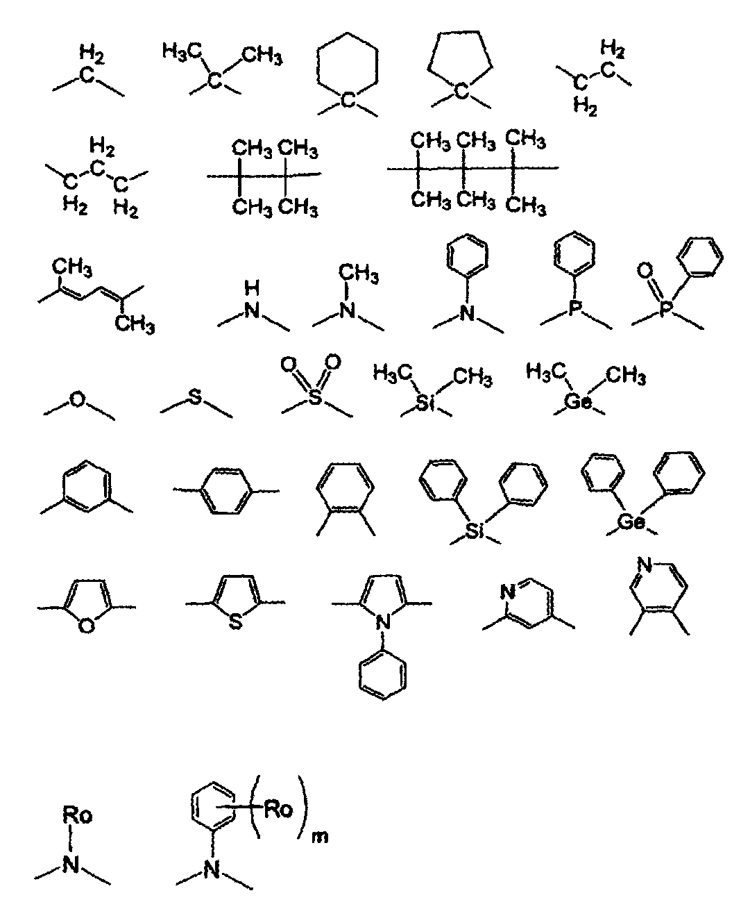
상기 화학식에서, Ro 는 치환기군 B 로부터 선택되는 치환기, 바람직하게는 알킬기, 더욱 바람직하게는 C1 -6 알킬기를 나타내고; m 은 0 내지 5, 바람직하게는 0 내지 4, 더욱 바람직하게는 0 내지 3 의 정수를 나타낸다.In the above formula, Ro is a substituent selected from Substituent Group B, preferably an alkyl group, more preferably represents a C 1 -6 alkyl group; m represents an integer of 0 to 5, preferably 0 to 4, more preferably 0 to 3.
L1 은 바람직하게는 디알킬메틸렌기, 디아릴메틸렌기 또는 디헤테로아릴메틸렌기, 더욱 바람직하게는 디메틸메틸렌기, 메틸페닐메틸렌기 또는 디페닐메틸렌기, 더욱 바람직하게는 디메틸메틸렌기를 나타낸다.L 1 preferably represents a dialkylmethylene group, a diarylmethylene group or a diheteroarylmethylene group, more preferably a dimethylmethylene group, a methylphenylmethylene group or a diphenylmethylene group, more preferably a dimethylmethylene group.
이들 연결기는 수소 원자로 치환될 수 있다. 이 경우 치환기의 예는 치환기군 B 의 치환기에 해당된다. 연결기가 둘 이상의 치환기를 갖는 경우, 치환기가 서로 커플링되어 고리를 형성할 수 있다.These linking groups may be substituted with hydrogen atoms. Examples of the substituent in this case correspond to the substituent of substituent group B. When the linking group has two or more substituents, the substituents may be coupled to each other to form a ring.
화학식 B-2 및 B-2' 가 이하 설명될 것이다.The formulas B-2 and B-2 'will be described below.
[화학식 B-2][Formula B-2]

[화학식 B-2'][Formula B-2 ']

화학식 B-2 및 B-2' 에서 R17, R18, R19, R20, RA 및 RB 는 화학식 1 에 정의된 바와 동일한 의미를 가지며, 이들의 바람직한 범위는 또한 화학식 1 에서의 그것과 동일하다.In the formulas B-2 and B-2 ', R 17 , R 18 , R 19 , R 20 , R A and R B have the same meanings as defined in formula (1) .
화학식 A-0 이 이하 설명될 것이다.The formula A-0 will be described below.
[화학식 A-0][A-0]

화학식 A-0 에서 R11, R12, R13, R14, R15, R16 및 L1 은 화학식 1 에 정의된 바와 동일한 의미를 가지며, 이들의 바람직한 범위는 또한 화학식 1 에서의 그것과 동일하다. X 는 수소 원자를 나타낸다. 할로겐 원자는 바람직하게는 불소 원자, 염소 원자, 브롬 원자 또는 요오드 원자, 더욱 바람직하게는 염소 원자, 브롬 원자 또는 요오드 원자, 더욱 바람직하게는 염소 원자 또는 브롬 원자이다.R 11 , R 12 , R 13 , R 14 , R 15 , R 16 and L 1 in formula A-0 have the same meanings as defined in formula (1), and their preferred ranges are also the same as those in formula Do. X represents a hydrogen atom. The halogen atom is preferably a fluorine atom, a chlorine atom, a bromine atom or an iodine atom, more preferably a chlorine atom, a bromine atom or an iodine atom, more preferably a chlorine atom or a bromine atom.
화학식 C-0 이 이하 설명될 것이다.The formula C-0 will be described below.
[화학식 C-0][Chemical formula C-O]

화학식 C-0 에서, R11, R12, R13, R14, R15, R16, R17, R18, R19, R20, RA, RB 및 L1 은 화학식 1 에 정의된 바와 동일한 의미를 가지며, 이들의 바람직한 범위는 또한 화학식 1 에서의 그것과 동일하다.R 1 , R 12 , R 13 , R 14 , R 15 , R 16 , R 17 , R 18 , R 19 , R 20 , R A , R B and L 1 in Formula C- And the preferred range thereof is also the same as that in the formula (1).
화학식 1 로 나타내어지는 백금 착물은 바람직하게는 화학식 2 로 나타내어지는 착물이다.The platinum complex represented by the formula (1) is preferably a complex represented by the formula (2).
[화학식 2](2)

화학식 2 에서, R11, R12, R13, R14, R15, R16, R17, R18, R19, R20, RA 및 RB 는 화학식 1 에서 정의된 바와 동일한 의미를 갖고, 이들의 바람직한 범위는 또한 화학식 1 에서의 그것과 동일하다. 각각의 R21 및 R22 는 독립적으로 수소 원자 또는 치환기를 나타낸다. 각각의 R21 및 R22 로 나타내어지는 치환기는 치환기군 B 에서와 동일한 의미를 갖는다. 대안적으로는, R21 및 R22 가 서로 조합되어, 시클릭 구조, 예컨대 시클로헥산 고리 또는 시클로펜탄 고리를 형성할 수 있다.In Formula 2, R 11 , R 12 , R 13 , R 14 , R 15 , R 16 , R 17 , R 18 , R 19 , R 20 , R A and R B have the same meanings as defined in Formula , And the preferable range thereof is also the same as that in the formula (1). Each of R 21 and R 22 independently represents a hydrogen atom or a substituent. The substituent represented by each of R 21 and R 22 has the same meaning as in substituent group B. Alternatively, R 21 and R 22 may be combined with each other to form a cyclic structure such as a cyclohexane ring or a cyclopentane ring.
각각의 R21 및 R22 는 바람직하게는 수소 원자, 알킬기, 아릴기, 할로겐 원자 또는 헤테로시클릭기, 더욱 바람직하게는 수소 원자, 메틸기, 페닐기, 불소 원자 또는 피리딜기, 더욱 바람직하게는 메틸기, 페닐기 또는 불소 원자, 가장 바람직하 게는 메틸기 또는 페닐기이다.Each of R 21 and R 22 is preferably a hydrogen atom, an alkyl group, an aryl group, a halogen atom or a heterocyclic group, more preferably a hydrogen atom, a methyl group, a phenyl group, a fluorine atom or a pyridyl group, A phenyl group or a fluorine atom, most preferably a methyl group or a phenyl group.
화학식 1 또는 2 로 나타내어지는 백금 착물은, 잔기가 중합체 사슬에 연결된 저분자량 화합물, 올리고머 화합물, 고분자량 화합물 (질량 평균 분자 중량이 바람직하게는 1000 내지 5000000, 더욱 바람직하게는 5000 내지 2000000, 더욱 바람직하게는 10000 내지 1000000 임), 또는 본 발명의 백금 착물의 구조를 주 사슬 내에 갖는 고분자량 화합물 (질량 평균 분자 중량이 바람직하게는 1000 내지 5000000, 더욱 바람직하게는 5000 내지 2000000, 더욱 바람직하게는 10000 내지 1000000 임) 일 수 있다. 이것이 고분자량 화합물인 경우, 이는 동종중합체, 또는 다른 중합체와의 공중합체일 수 있다. 공중합체는 랜덤 공중합체 또는 블록 공중합체일 수 있다. 공중합체는 그 중합체 내에 발광 관능기를 갖는 화합물 및/또는 전하 수송 기능을 갖는 화합물을 가질 수 있다.The platinum complex represented by the general formula (1) or (2) is preferably a low molecular weight compound, an oligomer compound, a high molecular weight compound (the mass average molecular weight is preferably 1000 to 5000000, more preferably 5000 to 2000000, Or a high molecular weight compound having a structure of the platinum complex of the present invention in the main chain (the mass average molecular weight is preferably 1000 to 5,000,000, more preferably 5000 to 200,000, and still more preferably 10000 To 1000000). If it is a high molecular weight compound, it may be a homopolymer, or a copolymer with another polymer. The copolymer may be a random copolymer or a block copolymer. The copolymer may have a compound having a light-emitting functional group and / or a compound having a charge-transporting function in the polymer.
하기는 화학식 1 로 나타내어지는 본 발명의 착물의 특정예인데, 본 발명이 이에 한정되는 것은 아니다.The following are specific examples of the complex of the present invention represented by the formula (1), but the present invention is not limited thereto.


본 발명의 제조 방법을 이하 설명할 것이다.The manufacturing method of the present invention will be described below.
화학식 1 로 나타내어지는 백금 착물의 제조 방법은, 피리딘 고리의 특정 위치 (피리딘의 질소 원자에 대해 a-위치) 에 치환기를 갖는 화학식 B-2 및 B-2' 로 나타내어지는 각각의 화합물을 화학식 A-0 으로 나타내어지는 화합물과 반응시켜, 하기 화학식 C-0 으로 나타내어지는 화합물을 수득하고; 하기 화학식 C-0 으로 나타내어지는 화합물을 백금 염과 반응시키는 것을 포함한다.The process for producing a platinum complex represented by the formula (1) is characterized in that each compound represented by the formula (B-2) and (B-2 ') having a substituent at a specific position of the pyridine ring (position a- to the nitrogen atom of the pyridine) -0 to obtain a compound of formula C-0; Reacting a compound represented by the following formula C-O with a platinum salt.

상기 반응식에서, R11, R12, R13, R14, R15, R16, R17, R18, R19, R20, RA, RB 및 L1 은 화학식 1 에서와 동일한 의미를 갖는다. X 는 할로겐 원자를 나타낸다.In the above formula, R 11 , R 12 , R 13 , R 14 , R 15 , R 16 , R 17 , R 18 , R 19 , R 20 , R A , R B and L 1 have the same meanings as in formula . X represents a halogen atom.
피리딘 고리의 특정 위치 (피리딘의 질소 원자에 대해 a-위치) 에 치환기를 갖는 화합물 B-2 를 리티오네이트화 생성물을 통해 화합물 B-3 또는 B-4 로부터 합성할 수 있다 (Org. Lett., 6, 277(2004) 에 기재). 화합물 B-2' 는 유사한 방식에 의해 합성할 수 있다.Compound B-2 having a substituent at a specific position of the pyridine ring (a-position relative to the nitrogen atom of pyridine) can be synthesized from Compound B-3 or B-4 via the lithiated product (Org. Lett. , 6, 277 (2004)). Compound B-2 'can be synthesized in a similar manner.

상기 반응식에서, R17, R18 및 RA 는 화학식 1 에 정의된 바와 동일한 의미를 갖는다.In the above reaction formula, R 17 , R 18 and R A have the same meanings as defined in formula (1).
하기 화학식 C-0 으로 나타내어지는 화합물은, 팔라듐 촉매, 리간드 (필요한 경우) 및 염기의 존재 하에서 용매 중에서 화학식 B-2 로 나타내어지는 화합물 및 화학식 B-2' 로 나타내어지는 화합물을 화학식 A-0 으로 나타내어지는 화합물과 반응시켜 합성할 수 있다.The compound represented by the formula C-0 is obtained by reacting the compound represented by the formula B-2 and the compound represented by the formula B-2 'in a solvent with a compound represented by the formula A-0 in the presence of a palladium catalyst, a ligand (if necessary) Can be synthesized by reacting with the indicated compound.
화학식 B-2 로 나타내어지는 화합물 및 화학식 B-2' 로 나타내어지는 화합물의 각각은 화학식 A-0 으로 나타내어지는 화합물의 1 몰 당 1.0 내지 10 mol, 바람직하게는 1.0 내지 6 mol, 더욱 바람직하게는 1.0 내지 3 mol 의 양으로 사용한다.Each of the compound represented by the formula (B-2) and the compound represented by the formula (B-2 ') is used in an amount of 1.0 to 10 mol, preferably 1.0 to 6 mol, per mol of the compound represented by the formula (A- It is used in an amount of 1.0 to 3 mol.
반응은 통상 상압에서 수행하지만, 필요에 따라 가압 또는 감압 하에서 수행할 수도 있다. 반응은 공기 중에서 수행할 수 있지만, 바람직하게는 비활성 분위기, 예컨대 질소 또는 아르곤에서 수행하여 팔라듐 촉매의 탈활성화를 방지한다.The reaction is usually carried out at atmospheric pressure, but may be carried out under pressure or reduced pressure, if necessary. The reaction can be carried out in air, but is preferably carried out in an inert atmosphere, such as nitrogen or argon, to prevent deactivation of the palladium catalyst.
상기 반응에서 사용할 수 있는 용매는 특별히 한정되지 않지만, 예로서 물, 방향족 탄화수소 예컨대 벤젠, 톨루엔 및 자일렌, 할로겐화 탄화수소 예컨대 디클로로에탄 및 클로로포름, 에테르 예컨대 테트라히드로푸란, 1,2-디메톡시에탄, 1,4-디옥산 및 디에틸 에테르, 알코올 예컨대 메탄올, 에탄올 및 이소프로필 알코올 및 에스테르 예컨대 에틸 아세테이트 및 부틸 아세테이트가 포함된다. 이중, 물, 방향족 탄화수소 및 에테르가 바람직하다. 이들 용매는 단독 또는 조합으로 사용될 수 있다.Examples of the solvent that can be used in the reaction include, but are not limited to, water, aromatic hydrocarbons such as benzene, toluene and xylene, halogenated hydrocarbons such as dichloroethane and chloroform, ethers such as tetrahydrofuran, 1,2-dimethoxyethane, , 4-dioxane and diethyl ether, alcohols such as methanol, ethanol and isopropyl alcohol and esters such as ethyl acetate and butyl acetate. Of these, water, aromatic hydrocarbons and ethers are preferred. These solvents may be used alone or in combination.
용매는 교반이 가능한 양으로 사용하며, 그 양은 화합물 A-0 의 중량을 기준으로 통상 1 내지 200 중량배, 바람직하게는 2 내지 100 중량배이다.The solvent is used in an amount capable of stirring, and the amount thereof is usually 1 to 200 times by weight, preferably 2 to 100 times by weight, based on the weight of the compound A-0.
상기 반응을 위하여는, 2가 팔라듐 염 또는 0-가 팔라듐 염이 팔라듐 촉매로 서 이용된다. 2가 팔라듐 염의 예는 팔라듐 아세테이트 및 디클로로비스트리페닐포스핀 팔라듐을 포함하고, 0-가 팔라듐 염의 예는 테트라키스트리페닐포스핀 팔라듐 및 비스(디벤질리덴아세톤)팔라듐을 포함한다.For this reaction, a divalent palladium salt or a 0-palladium salt is used as a palladium catalyst. Examples of divalent palladium salts include palladium acetate and dichlorobistriphenylphosphine palladium, and examples of 0-valent palladium salts include tetrakistriphenylphosphine palladium and bis (dibenzylideneacetone) palladium.
팔라듐 염은 화합물 A-0 의 1 몰 당 통상 0.0001 내지 0.5 mol, 바람직하게는 0.001 내지 0.2 mol, 더욱 바람직하게는 0.005 내지 0.1 mol 의 양으로 사용된다.The palladium salt is used in an amount of usually 0.0001 to 0.5 mol, preferably 0.001 to 0.2 mol, more preferably 0.005 to 0.1 mol, per 1 mol of the compound A-0.
상기 반응은 필요에 따라 리간드를 첨가하여 수행할 수 있다. 리간드의 예는 포스핀 리간드 및 카르벤 리간드를 포함한다. 이중, 포스핀 리간드가 바람직하다.The reaction can be carried out by adding a ligand as required. Examples of ligands include phosphine ligands and carbin ligands. Of these, phosphine ligands are preferred.
리간드는 반응에 사용되는 팔라듐 촉매의 1 몰 당 통상 0.5 내지 20 mol, 바람직하게는 1 내지 10 mol, 더욱 바람직하게는 1 내지 5 mol 의 양으로 사용된다.The ligand is usually used in an amount of 0.5 to 20 mol, preferably 1 to 10 mol, more preferably 1 to 5 mol per mol of the palladium catalyst used in the reaction.
반응에 사용되는 염기는 특별히 한정되지는 않지만, 특정 예로서 알칼리금속 히드록사이드 예컨대 리튬 히드록사이드, 나트륨 히드록사이드 및 칼륨 히드록사이드; 알칼리 토금속 히드록사이드 예컨대 칼슘 히드록사이드 및 바륨 히드록사이드, 알칼리금속 바이카르보네이트 예컨대 나트륨 바이카르보네이트 및 칼륨 바이카르보네이트; 알칼리 토금속 바이카르보네이트 예컨대 칼슘 바이카르보네이트 및 바륨 바이카르보네이트, 알칼리금속 카르보네이트 예컨대 나트륨 카르보네이트 및 칼슘 카르보네이트, 알칼리 토금속 카르보네이트 예컨대 칼슘 카르보네이트 및 바륨 카르보네이트 및 포스페이트 예컨대 나트륨 포스페이트 및 칼륨 포스페이트가 포함된다. 이중, 알칼리금속 바이카르보네이트, 알칼리금속 카르보네이트 및 포스페이트가 바람직하다.The base used in the reaction is not particularly limited, but specific examples include alkali metal hydroxides such as lithium hydroxide, sodium hydroxide and potassium hydroxide; Alkaline earth metal hydroxides such as calcium hydroxide and barium hydroxide, alkali metal bicarbonates such as sodium bicarbonate and potassium bicarbonate; Alkaline earth metal bicarbonates such as calcium bicarbonate and barium bicarbonate, alkali metal carbonates such as sodium carbonate and calcium carbonate, alkaline earth metal carbonates such as calcium carbonate and barium carbonate And phosphates such as sodium phosphate and potassium phosphate. Of these, alkali metal bicarbonates, alkali metal carbonates and phosphates are preferred.
염기는 화합물 A-0 의 1 몰 당 통상 0.1 내지 50 mol, 바람직하게는 1 내지 20 mol, 더욱 바람직하게는 2 내지 10 mol 의 양으로 사용된다.The base is used in an amount of usually 0.1 to 50 mol, preferably 1 to 20 mol, more preferably 2 to 10 mol, per 1 mol of the compound A-0.
상기 반응의 온도는 특별히 한정되지 않지만, 통상 0 ℃ 내지 용매의 비등점이다. 생성물의 분해가 일어나지 않는 경우에는, 반응을 용매의 비등점 근처 온도에서 수행하여 반응률을 향상시킨다. The temperature of the reaction is not particularly limited, but is usually from 0 ° C to the boiling point of the solvent. When the decomposition of the product does not occur, the reaction is carried out at a temperature near the boiling point of the solvent to improve the reaction rate.
화학식 1 로 나타내어지는 백금 착물은, 용매의 존재 하에서 하기 화학식 C-0 으로 나타내어지는 화합물 (이하, "리간드" 라 칭함) 을 백금 염과 반응시킴으로써 수득할 수 있다.The platinum complex represented by the formula (1) can be obtained by reacting a compound represented by the following formula (C-0) (hereinafter referred to as "ligand") with a platinum salt in the presence of a solvent.
본 발명의 제조 방법에서, 백금 염 및 리간드 사이의 착물을 형성하기 위해 반응시 사용되는 백금 염의 예로는 2가 백금을 포함하는 것으로서 백금 클로라이드, 백금 브로마이드, 백금 요오다이드, 백금 아세틸아세토네이트, 비스(벤조니트릴)디클로로백금, 비스(아세토니트릴)디클로로백금, 디클로로(1,5-시클로옥타디엔)백금, 디브로모비스(트리페닐포스핀)백금, 디클로로(1,10-페난트롤린)백금, 디클로로비스(트리페닐포스핀)백금, 디암민디클로로백금, 디암민디요오도백금, 칼륨 테트라브로모플라티네이트, 칼륨 테트라클로로플라티네이트 및 나트륨 테트라클로로플라티네이트를 포함한다. 이들 백금 염 중, 백금 클로라이드, 비스(벤조니트릴)디클로로백금(II) 및 비스(아세토니트릴)디클로로백금(II) 이 특히 바람직하다.Examples of the platinum salt used in the reaction for forming the complex between the platinum salt and the ligand in the production method of the present invention include platinum chloride, platinum bromide, platinum iodide, platinum acetylacetonate, bis (1,5-cyclooctadiene) platinum, dibromobis (triphenylphosphine) platinum, dichloro (1,10-phenanthroline) platinum, dibromo Dichlorobis (triphenylphosphine) platinum, diamminedichloroplatinum, diamminediiodoplatinum, potassium tetrabromoplatinate, potassium tetrachloroplatinate, and sodium tetrachloroplatinate. Of these platinum salts, platinum chloride, bis (benzonitrile) dichloroplatinum (II) and bis (acetonitrile) dichloroplatinum (II) are particularly preferred.
이들 금속 화합물은 결정수, 결정 용매 또는 배위 용매를 포함할 수 있다. 금속의 원자가는 특별히 한정되지 않지만, 금속은 바람직하게는 2가 또는 0-가, 더욱 바람직하게는 2가이다.These metal compounds may include crystal water, a crystal solvent or a coordination solvent. The valence of the metal is not particularly limited, but the metal is preferably divalent or 0-, more preferably divalent.
본 발명의 제조 방법에서, 백금 염 및 리간드 사이의 착물 형성 반응에 사용되는 백금 염의 양은 그 백금 염이, 상응하는 착물을 형성하는 백금 원자를 1 개 함유하는 경우, 리간드의 1 몰 당 통상 0.1 내지 10 mol, 바람직하게는 0.5 내지 5 mol, 더욱 바람직하게는 1 내지 3 mol 이다. 백금 염이, 상응하는 착물을 형성하는 백금 원자를 n 개 함유하는 경우, 그 양은 1/n mol 일 수 있다.In the production method of the present invention, the amount of the platinum salt used in the complex formation reaction between the platinum salt and the ligand is usually from 0.1 to 1 mol per mol of the ligand, when the platinum salt contains one platinum atom forming the corresponding complex 10 mol, preferably 0.5 to 5 mol, more preferably 1 to 3 mol. When the platinum salt contains n platinum atoms to form the corresponding complex, the amount can be 1 / n mol.
본 제조 방법에서 백금 염 및 리간드 사이의 착물화 반응시 사용되는 용매의 예는 아미드 예컨대 N,N-디메틸포름아미드, 포름아미드 및 N,N-디메틸아세트아미드, 니트릴 예컨대 아세토니트릴, 프로피오니트릴, 부티로니트릴 및 벤조니트릴, 할로겐화 탄화수소 예컨대 디클로로메탄, 1,2-디클로로에탄, 클로로포름, 탄소 테트라클로라이드, 클로로벤젠 및 o-디클로로벤젠, 지방족 탄화수소 예컨대 펜탄, 헥산, 옥탄 및 데칸, 방향족 탄화수소 예컨대 벤젠, 톨루엔, 자일렌 및 메시틸렌, 에테르 예컨대 디에틸 에테르, 디이소프로필 에테르, 부틸 에테르, tert-부틸 메틸 에테르, 1,2-디메톡시에탄, 테트라히드로푸란 및 1,4-디옥산, 케톤 예컨대 아세톤, 메틸 에틸 케톤 및 메틸 이소부틸 케톤, 알코올 화합물 예컨대 메탄올, 에탄올, 1-프로판올, 2-프로판올, tert-부틸 알코올, 2-메톡시에탄올, 2-에톡시에탄올, 에틸렌 글리콜 및 글리세린, 카르복실산 예컨대 아세트산 및 프로피온산 및 물을 포함한다. 이들 용매 중, 니트릴 예컨대 아세토니트릴, 프로피오니트릴, 부티로니트릴 및 벤조니트릴 및 방향족 탄화수소 예컨대 벤젠, 톨루엔, 자일렌 및 메시틸렌이 이들 중 특히 바람직하다. 이러한 용매는 단독으로 또는 이의 둘 이상의 조합으로 사용될 수 있다.Examples of the solvent used in the complexation reaction between the platinum salt and the ligand in the present production method include amides such as N, N-dimethylformamide, formamide and N, N-dimethylacetamide, nitriles such as acetonitrile, Dichloroethane, chloroform, carbon tetrachloride, chlorobenzene and o-dichlorobenzene, aliphatic hydrocarbons such as pentane, hexane, octane and decane, aromatic hydrocarbons such as benzene, toluene and xylene, aliphatic hydrocarbons such as benzene, Toluene, xylene and mesitylene, ethers such as diethyl ether, diisopropyl ether, butyl ether, tert-butyl methyl ether, 1,2-dimethoxyethane, tetrahydrofuran and 1,4-dioxane, , Methyl ethyl ketone and methyl isobutyl ketone, alcohol compounds such as methanol, ethanol, 1-propanol, 2-propanol, tert-butyl Alcohol, 2-methoxyethanol, include ethoxyethanol, ethylene glycol and glycerin, carboxylic acids such as acetic acid and propionic acid and water in 2. Of these solvents, nitriles such as acetonitrile, propionitrile, butyronitrile and benzonitrile and aromatic hydrocarbons such as benzene, toluene, xylene and mesitylene are particularly preferred. These solvents may be used alone or in combination of two or more thereof.
본 발명의 제조 방법에서, 백금 염 및 리간드 사이의 착물 형성 반응시 사용되는 용매의 양은 반응을 충분히 진행할 수 있는 양이면 특별히 한정되지 않는다. 반응에 사용되는 리간드의 부피에 대해 통상 1 내지 200 부피배, 바람직하게는 5 내지 100 부피배이다.In the production method of the present invention, the amount of the solvent used in the complex formation reaction between the platinum salt and the ligand is not particularly limited as far as the reaction can proceed sufficiently. Is usually 1 to 200 times by volume, preferably 5 to 100 times by volume with respect to the volume of the ligand used in the reaction.
본 발명의 제조 방법에서, 산성 물질 예컨대 할로겐화 수소가 백금 염 및 리간드 사이의 착물 형성 반응 도중 형성되는 경우, 반응을 염기성 물질의 존재 하에서 수행할 수 있다. 염기성 물질의 예는 3차 아민 예컨대 트리에틸아민, 디이소프로필에틸아민 및 피리딘, 금속 알콕사이드 예컨대 나트륨 메톡사이드 및 나트륨 에톡사이드 및 무기 염기 예컨대 나트륨 히드록사이드, 칼륨 히드록사이드, 칼륨 카르보네이트 및 나트륨 바이카르보네이트를 포함한다. 대안적으로는, 착물화시에 생성된 산성 물질, 예컨대 수소 할로겐화물을 반응 용액으로부터 제거하거나 또는 반응 용액에 비활성 가스, 예컨대 질소 또는 아르곤을 불어넣어 반응 용액 내에서 그 함량을 감소시킬 수 있다.In the production process of the present invention, when an acidic substance such as hydrogen halide is formed during the complex formation reaction between the platinum salt and the ligand, the reaction can be carried out in the presence of a basic substance. Examples of basic materials are tertiary amines such as triethylamine, diisopropylethylamine and pyridine, metal alkoxides such as sodium methoxide and sodium ethoxide, and inorganic bases such as sodium hydroxide, potassium hydroxide, potassium carbonate and Sodium bicarbonate. Alternatively, the acidic substance produced during the complexation, such as the hydrogen halide, may be removed from the reaction solution, or an inert gas such as nitrogen or argon may be blown into the reaction solution to reduce its content in the reaction solution.
본 발명의 제조 방법에서, 백금 염 및 리간드 사이의 착물 형성 반응은 바람직하게는 비활성 기체 분위기 하에서 수행된다. 비활성 기체의 예는 질소 및 아르곤을 포함한다.In the production process of the present invention, the complex formation reaction between the platinum salt and the ligand is preferably carried out under an inert gas atmosphere. Examples of inert gases include nitrogen and argon.
본 발명의 반응에서 백금 염 및 리간드 사이의 착물 형성 반응에서의 반응 온도, 반응 시간 및 반응 압력의 각각은 원료 재료 또는 용매에 따라 다르다. 반응 온도 통상 20 내지 300 ℃, 바람직하게는 50 내지 250 ℃, 더욱 바람직하게는 80 내지 220 ℃ 이고; 반응 시간은 통상 30 분 내지 24 시간, 바람직하게는 1 내지 12 시간, 더욱 바람직하게는 2 내지 10 시간이고; 반응 압력은 통상 상압인데, 필요에 따라 가압 또는 감압 하일 수 있다.In the reaction of the present invention, the reaction temperature, the reaction time, and the reaction pressure in the complex formation reaction between the platinum salt and the ligand are different depending on the raw material or the solvent. The reaction temperature is usually 20 to 300 占 폚, preferably 50 to 250 占 폚, more preferably 80 to 220 占 폚; The reaction time is usually 30 minutes to 24 hours, preferably 1 to 12 hours, more preferably 2 to 10 hours; The reaction pressure is usually normal pressure, which may be pressurized or reduced pressure as required.
본 발명의 제조 방법에서, 백금 염 및 리간드 사이의 착물 형성 반응시 사용되는 가열 수단은 특별히 한정되지 않는다. 예를 들어, 오일 배스에서의 가열, 맨틀 히터 내 가열이나, 또는 마이크로파 조사에 의한 가열을 이용할 수 있다.In the production method of the present invention, the heating means used in the complex formation reaction between the platinum salt and the ligand is not particularly limited. For example, heating in an oil bath, heating in a mantle heater, or heating by microwave irradiation can be used.
본 발명의 착물인 하기 화학식 D-1 로 나타내어지는 화합물의 제조 방법을 이하 상세히 기술할 것이다.The method for preparing the compound represented by the following formula (D-1) which is the complex of the present invention will be described in detail below.

식 중, R11, R12, R13, R14, R15, R16, R17, R18, R21, R22 및 RA 는 화학식 2 에서 정의된 바와 동일한 의미를 갖는다.In the formula, R 11 , R 12 , R 13 , R 14 , R 15 , R 16 , R 17 , R 18 , R 21 , R 22 and R A have the same meanings as defined in formula (2).
본 발명의 착물은 문헌 [Journal of Organic Chemistry, 53, 786 (1988), G.R. Newkome 등] 의 789 쪽, 좌측 칼럼 53 행 내지 우측 칼럼 7 행에 기록된 방법, 또는 동일 문헌의 790 쪽, 좌측 칼럼 18 행 내지 38 행 및 우측 칼럼 19 행 내지 30 행에 기록된 방법 및 이들 방법의 조합에 의해 수득될 수 있다. 화합물 A-1 을 출발 물질로 사용했다. 화합물 A-1 의 N,N-디메틸포름아미드 용액에 1 내지 1.2 당량의 염기, 예컨대 리튬 디이소프로필아미드, 칼륨 t-부톡사이드 또는 나트륨 히드라이드를 0 ℃ 내지 실온에서 첨가했다. 생성된 혼합물을 0 ℃ 내지 실온에서 약 30 분 동안 반응시킨다. 반응 혼합물에 1.5 내지 4 당량의 알킬 할라이드 R21X (R21 은 화학식 2 에 앞서 정의한 바와 같은 동일한 의미를 갖고, X 는 할로겐 원자를 나타냄) 을 첨가하고, 혼합물을 실온에서 약 30 분 동안 반응시켜, 해당하는 모노알킬화를 수행한다. 유사한 조건 하에서, 1 내지 1.2 당량의 염기를 과량의 알킬 할라이드 R22X (R22 는 화학식 2 에 앞서 정의한 바와 같은 동일한 의미를 갖고, X 는 할로겐 원자를 나타냄) 와 반응시켜서, 디알킬-치환된 화합물 B-1 를 70 내지 99 % 의 수율로 수득할 수 있다. 알킬 할라이드로서 1,4-디브로모부탄 등을 사용하여 시클로펜탄 고리를 갖는 화합물 B-1 을 합성할 수 있고, 또한 알킬 할라이드로서 1,5-디브로모펜탄 등을 사용하여 시클로헥산 고리를 갖는 화합물 B-1 을 합성할 수 있다.The complexes of the present invention can be synthesized by the method described in Journal of Organic Chemistry, 53, 786 (1988), GR Newkome et al., Page 789, left column, line 53 to right column, 18 to 38 and the right column, lines 19 to 30, and combinations of these methods. Compound A-1 was used as a starting material. 1 to 1.2 equivalents of a base such as lithium diisopropylamide, potassium t-butoxide or sodium hydride was added to the N, N-dimethylformamide solution of Compound A-1 at 0 캜 to room temperature. The resulting mixture is allowed to react at 0 < 0 > C to room temperature for about 30 minutes. To the reaction mixture is added 1.5 to 4 equivalents of an alkyl halide R 21 X (R 21 has the same meaning as defined above for formula 2 and X represents a halogen atom) and the mixture is reacted at room temperature for about 30 minutes , The corresponding monoalkylation is carried out. Under similar conditions, 1 to 1.2 equivalents of base are reacted with excess alkyl halide R 22 X (R 22 Has the same meaning as defined above in formula (2), and X represents a halogen atom), whereby the dialkyl-substituted compound B-1 can be obtained in a yield of 70 to 99%. Compound B-1 having a cyclopentane ring can be synthesized by using 1,4-dibromobutane or the like as the alkyl halide, and a cyclohexane ring can be obtained by using 1,5-dibromopentane or the like as the alkyl halide Can be synthesized.
화합물 B-1 로부터 화합물 C-1 을 수득하는 단계로서, 문헌 [Synth. Commun., 11, 513(1981)] 에 기술된 방법을 이용하여 목적 화합물을 합성할 수 있다.The step of obtaining compound C-1 from compound B-1 is described in Synth. Commun., 11, 513 (1981) can be used to synthesize the desired compound.
본 발명의 화합물 D-1 은 하기 방식에 의해 화합물 C-1 로부터 수득할 수 있다. 화합물 C-1, 및 1 내지 1.5 당량의 백금 클로라이드를 벤조니트릴 중에 용해시키고, 생성된 용액을 130 ℃ 내지 환류 온도 (벤조니트릴의 비등점: 191 ℃) 로 가열하고, 반응 혼합물을 30 분 내지 4 시간 동안 교반하여 합성할 수 있다. 화합물 D-1 을 클로로포름 또는 에틸 아세테이트로부터의 재결정, 실리카 겔 컬럼 크로마토그래피 또는 승화에 의해 정제할 수 있다.The compound D-1 of the present invention can be obtained from the compound C-1 in the following manner. Compound C-1 and 1 to 1.5 equivalents of platinum chloride are dissolved in benzonitrile and the resulting solution is heated from 130 占 폚 to reflux temperature (boiling point of benzonitrile: 191 占 폚) and the reaction mixture is stirred for 30 minutes to 4 hours ≪ / RTI > Compound D-1 can be purified by recrystallization from chloroform or ethyl acetate, silica gel column chromatography or by sublimation.
본 발명의 백금 착물 중, 하기 화학식 H-1 로 나타내어지는 착물이 하기 제조 방법에 의해 합성될 수 있다.Among the platinum complexes of the present invention, a complex represented by the following formula (H-1) can be synthesized by the following production method.

상기 반응식에서, R11, R12, R13, R14, R15, R16, R17, R18 및 RA 는 화학식 2 에서 정의된 바와 동일한 의미를 갖고; Ro 는 치환기군 B 로부터 선택된 치환기를 나타내고, m 은 0 내지 5 의 정수를 나타낸다.In the above reaction formula, R 11 , R 12 , R 13 , R 14 , R 15 , R 16 , R 17 , R 18 and R A have the same meanings as defined in Formula 2; Ro represents a substituent selected from Substituent Group B, and m represents an integer of 0 to 5;
화합물 E-1 로부터 화합물 F-1 을 수득하는 단계 또는 화합물 E-2 로부터 화합물 F-2 를 수득하는 단계로서, 문헌 [Synth. Commun., 11, 513(1981)] 에 기술된 방법을 이용하여 목적 화합물을 합성할 수 있다.The step of obtaining compound F-1 from compound E-1 or the step of obtaining compound F-2 from compound E-2 is described in Synth. Commun., 11, 513 (1981) can be used to synthesize the desired compound.
화합물 F-1 또는 화합물 F-2 로부터 화합물 G-1 를 수득하는 단계로서, 문헌 [Angew. Chem. Int. Ed., 42, 2051-2053(2003)] 에 기술된 방법을 이용하여 목적 화합물을 합성할 수 있다.The step of obtaining compound G-1 from compound F-1 or compound F-2 is described in Angew. Chem. Int. Ed., 42, 2051-2053 (2003), the desired compound can be synthesized.
화합물 G-1, 및 1 내지 1.5 당량의 백금 클로라이드를 벤조니트릴 중에 용해시키고, 생성된 용액을 130 ℃ 내지 환류 온도 (벤조니트릴의 비등점: 191 ℃) 로 가열하고, 반응 혼합물을 30 분 내지 4 시간 동안 교반함으로써 화합물 G-1 로부터 본 발명의 화합물 H-1 을 합성할 수 있다. 화합물 H-1 을 클로로포름 또는 에틸 아세테이트로부터의 재결정, 실리카 겔 컬럼 크로마토그래피 또는 승화에 의해 정제할 수 있다.Compound G-1 and 1 to 1.5 equivalents of platinum chloride are dissolved in benzonitrile and the resulting solution is heated from 130 占 폚 to reflux temperature (boiling point of benzonitrile: 191 占 폚) and the reaction mixture is stirred for 30 minutes to 4 hours The compound H-1 of the present invention can be synthesized from the compound G-1. Compound H-1 can be purified by recrystallization from chloroform or ethyl acetate, silica gel column chromatography or by sublimation.
상기 제조 방법에서, 정의된 치환기가 특정 합성 조건 하에서 변화되거나 또는 그 방법을 구현하는 데 있어서 부적절한 경우, 예를 들어, 보호 또는 탈보호 관능기를 이용하여 목적 화합물을 용이하게 제조하는 것이 가능하다 (예를 들어, Protective Groups in Oraganic Synthesis, T. W. Greene, John Wiley & Sons Inc., 1981 참조). 필요한 경우, 치환기의 도입과 같은 반응 단계의 순서를 적절히 변경하는 것이 또한 가능하다.In the above process, it is possible to easily prepare the desired compound using, for example, a protecting or deprotecting functional group when the defined substituent is changed under certain synthesis conditions or is unsuitable for implementing the method , Protective Groups in Organic Synthesis, TW Greene, John Wiley & Sons Inc., 1981). If necessary, it is also possible to appropriately change the order of the reaction steps such as the introduction of a substituent.
다음으로, 본 발명의 소자에 대해 상세히 설명한다.Next, the device of the present invention will be described in detail.
본 발명의 소자는 한 쌍의 전극, 및 그 한 쌍의 전극 사이에 하나 이상의 유기층을 갖는 유기 전계 발광 소자로서, 본 발명의 백금 착물 중 하나 이상이 상기 하나 이상의 유기층에 포함된다. 소자가 하나의 유기층을 갖는 경우, 이는 유기층으로서 발광층을 갖는다. 전극, 즉 애노드 및 캐소드 중 하나 이상은 소자의 성질을 고려할 때, 바람직하게는 투명 또는 반투명하다.An element of the present invention is an organic electroluminescent element having a pair of electrodes and at least one organic layer between the pair of electrodes, wherein at least one of the platinum complexes of the present invention is contained in the at least one organic layer. When the device has one organic layer, it has a light emitting layer as an organic layer. At least one of the electrodes, i.e., the anode and the cathode, is preferably transparent or translucent, considering the nature of the device.
본 발명의 소자는, 이의 하나 이상의 유기층이 특정 구조의 네자리 배위자를 갖는 착물을 함유하는 것을 특징으로 한다. 유기층은 특별히 한정되지 않지만, 상기 소자는 발광층에 더하여 정공 주입층, 정공 수송층, 전자 주입층, 전자 수송층, 정공 차단층, 전자 차단층, 여기자 차단층 및 보호층을 가질 수 있다. 이들 층들의 각각은 다른 추가적 기능을 동시에 가질 수 있다.The device of the present invention is characterized in that the at least one organic layer contains a complex having a four-terminal ligand of a specific structure. The organic layer is not particularly limited, but the device may have a hole injecting layer, a hole transporting layer, an electron injecting layer, an electron transporting layer, a hole blocking layer, an electron blocking layer, an exciton blocking layer and a protective layer in addition to the light emitting layer. Each of these layers may have other additional functions at the same time.
본 발명에서의 유기층의 층 구조로서는, 애노드측으로부터 정공 수송층, 발광층 및 전자 수송층의 순서로 포함되는 것이 바람직하다. 또한, 소자는 정공 수송층 및 발광층 사이에, 또는 발광층 및 전자 수송층 사이에 전자 차단층 등을 가질 수 있다. 소자는 애노드 및 정공 수송층 사이에 정공 주입층을 가질 수 있다. 이와 유사하게, 캐소드 및 전자 수송층 사이에 전자 주입층을 가질 수 있다. 각각의 층은 복수의 하위층으로 나뉠 수 있다.The layer structure of the organic layer in the present invention preferably includes the hole transporting layer, the light emitting layer and the electron transporting layer in this order from the anode side. The device may have an electron blocking layer between the hole transporting layer and the light emitting layer, or between the light emitting layer and the electron transporting layer. The device may have a hole injecting layer between the anode and the hole transporting layer. Similarly, an electron injecting layer may be provided between the cathode and the electron transporting layer. Each layer can be divided into a plurality of lower layers.
소자가 둘 이상의 유기층을 갖는 경우, 본 발명의 착물이 상기 층 중 임의의 층에 포함될 수 있다. 본 발명의 착물은 바람직하게는 발광층에 포함되고, 더욱 바람직하게는 발광 재료 또는 호스트 재료로서 발광층에 포함되고, 더욱 바람직하게는 발광 재료로서 발광층에 포함되고, 특히 바람직하게는 하나 이상의 호스트 재료와 함께 발광층에 포함된다. Where the device has two or more organic layers, the complex of the present invention may be included in any of the layers. The complex of the present invention is preferably contained in the light emitting layer, more preferably included in the light emitting layer as the light emitting material or the host material, more preferably included in the light emitting layer as the light emitting material, and particularly preferably, Emitting layer.
본 발명의 착물이 발광층 이외의 층 (예를 들어, 전자 수송층) 에 도입되는 경우, 바람직하게는 10 내지 100 질량%, 더욱 바람직하게는 30 내지 100 질량% 의 양으로 포함된다.When the complex of the present invention is introduced into a layer other than the light emitting layer (for example, an electron transporting layer), it is preferably contained in an amount of 10 to 100 mass%, more preferably 30 to 100 mass%.
다음으로, 본 발명의 소자를 구성하는 개별 요소에 대해 상세히 설명할 것이다. Next, the individual elements constituting the element of the present invention will be described in detail.
<기판> <Substrate>
본 발명에 사용되는 기판은 바람직하게는 유기층으로부터 방출되는 광을 산란 또는 감쇄시키지 않는 기판이다. 특정 예는 무기 재료 예컨대 이트륨-안정화 지르코니아 (YSZ) 및 유리; 유기 재료 예컨대 폴리에스테르, 예를 들어, 폴리에틸렌 테레프탈레이트, 폴리부틸렌 테레프탈레이트 및 폴리에틸렌 나프탈레이트, 폴리스티렌, 폴리카르보네이트, 폴리에테르술폰, 폴리아릴레이트, 폴리이미드, 폴리시클로올레핀, 노르보르넨 수지, 폴리(클로로트리플루오로에틸렌) 을 포함한다.The substrate used in the present invention is preferably a substrate which does not scatter or attenuate light emitted from the organic layer. Specific examples include inorganic materials such as yttrium-stabilized zirconia (YSZ) and glass; Organic materials such as polyesters such as polyethylene terephthalate, polybutylene terephthalate and polyethylene naphthalate, polystyrene, polycarbonate, polyethersulfone, polyarylate, polyimide, polycycloolefin, norbornene resin , And poly (chlorotrifluoroethylene).
예를 들어, 유리를 기판으로서 사용하는 경우, 유리로부터의 이온 방출을 최소화시키기 위해 알칼리-비함유 유리를 사용하는 것이 바람직하다. 소다 석회 유리를 사용하는 경우, 예를 들어, 실리카로 코팅된 차단벽이 바람직하다. 유기 재료로 만들어진 기판이 내열성, 치수 안정성, 내용매성, 전기 절연성, 및 가공성이 우수하기 때문에 바람직하다.For example, when using glass as a substrate, it is preferable to use an alkali-free glass in order to minimize ion emission from the glass. In the case of using soda lime glass, for example, silica-coated barrier walls are preferred. A substrate made of an organic material is preferable because it is excellent in heat resistance, dimensional stability, solvent resistance, electrical insulation, and workability.
기판의 형상, 구조, 크기 등은 특별히 한정되지 않으며, 발광 소자의 의도하고 있는 용도 또는 목적에 따라 적절히 선택될 수 있다. 일반적으로, 기판은 바람직하게는 플레이트 형상을 가지며, 단일층 구조 또는 다중층 구조를 가질 수 있다. 이는 단일 부재 또는 둘 이상의 부재로 만들어질 수 있다.The shape, structure, size, and the like of the substrate are not particularly limited, and may be appropriately selected depending on the intended use or purpose of the light emitting device. In general, the substrate preferably has a plate shape and may have a single layer structure or a multilayer structure. It can be made of a single member or two or more members.
기판은 무색 투명하거나, 또는 유색 투명할 수 있지만, 무색 투명한 기판이 유기 발광층으로부터 방출되는 광을 산란 또는 감쇄시키지 않기 때문에 바람직하다.The substrate may be colorless transparent or colored transparent, but a colorless transparent substrate is preferable because it does not scatter or attenuate light emitted from the organic light emitting layer.
기판은 이의 정면 또는 후면 상에 수분 침투 방지층 (또는 기체 차단벽 층) 을 가질 수 있다.The substrate may have a moisture impermeable layer (or gas barrier wall layer) on its front or rear surface.
수분 침투 방지층 (또는 기체 차단벽 층) 용 재료는 무기 물질, 예컨대 규소 니트라이드 및 규소 옥사이드가 적절하다. 수분 침투 방지층 (기체 차단벽 층) 은, 예를 들어, RF 스퍼터링에 의해 형성될 수 있다.An inorganic material such as silicon nitride and silicon oxide is suitable as the material for the moisture permeation preventing layer (or the gas barrier wall layer). The water permeation preventing layer (gas barrier wall layer) can be formed by, for example, RF sputtering.
열가소성 기판을 사용하는 경우, 필요한 경우, 기판이 하드 코트층 또는 언더 코트층을 추가로 가질 수 있다.If a thermoplastic substrate is used, the substrate may additionally have a hard coat layer or an undercoat layer, if desired.
<애노드><Anode>
애노드는 유기층에 정공을 공급하는 전극으로서의 기능을 갖는 한 통상 형상, 구조, 크기 등에 제한을 갖지 않는다. 애노드의 재료는 발광 소자의 의도하고 있는 용도 또는 목적에 따라, 공지된 전극 재료로부터 적절히 선택될 수 있다. 상기된 바와 같이, 애노드는 통상 투명 애노드로서 형성된다.The anode has no limitation on the shape, structure, size, and the like, as long as it has a function as an electrode for supplying holes to the organic layer. The material of the anode can be appropriately selected from known electrode materials, depending on the intended use or purpose of the light emitting element. As described above, the anode is usually formed as a transparent anode.
애노드 재료의 예는 금속, 합금, 금속 옥사이드, 전기 전도성 화합물, 및 이의 혼합물을 포함한다. 애노드 재료의 특정 예는 전도성 금속 옥사이드, 예컨대 안티몬 및 불소로 도핑된 주석 옥사이드 (예를 들어, ATO 또는 FTO), 주석 옥사이드, 아연 옥사이드, 인듐 옥사이드, 인듐 주석 옥사이드 (ITO), 및 인듐 아연 옥사이드 (IZO), 금속, 예컨대 금, 은, 크롬 및 니켈, 이들 금속 및 전도성 금속 옥사이드로 이루어진 혼합물 또는 복합체 적층물; 무기 전도성 물질, 예컨대 구리 요오다이드 및 구리 술파이드, 유기 전도성 재료, 예컨대 폴리아닐린, 폴리티오펜, 및 폴리피롤; 및 이들 재료 및 ITO 의 적층물을 포함한다. 이들 재료 중, 생산성, 고 전도성 및 투명성 등의 관점에서 전기 전도성 금속 옥사이드가 바람직하고, 특히 ITO 가 바람직하다.Examples of anode materials include metals, alloys, metal oxides, electrically conductive compounds, and mixtures thereof. Specific examples of the anode material include conductive metal oxides such as tin oxide (e.g., ATO or FTO) doped with antimony and fluorine, tin oxide, zinc oxide, indium oxide, indium tin oxide (ITO), and indium zinc oxide IZO), metals such as gold, silver, chromium and nickel, mixtures or composite laminates of these metals and conductive metal oxides; Inorganic conductive materials such as copper iodide and copper sulfide, organic conductive materials such as polyaniline, polythiophene, and polypyrrole; And a laminate of these materials and ITO. Among these materials, an electrically conductive metal oxide is preferable from the standpoints of productivity, high conductivity and transparency, and ITO is particularly preferable.
애노드는 습식 공정, 예컨대 인쇄 및 코팅, 물리적 공정, 예컨대 진공 증착, 스퍼터링 및 이온 도금법, 및 화학적 공정, 예컨대 CVD 및 플라즈마 CVD 로부터, 애노드를 구성하는 재료에 대한 안정성을 고려하여 적절히 선택한 방법에 의해 기판 상에 형성할 수 있다. ITO 를 애노드 재료로서 선택한 경우, 애노드를 DC 스퍼터링, RF 스퍼터링, 진공 증착 또는 이온 도금법에 의해 형성할 수 있다.The anode can be formed by a wet process, such as printing and coating, physical processes such as vacuum deposition, sputtering and ion plating, and chemical processes such as CVD and plasma CVD, by a suitably selected method in view of the stability of the materials constituting the anode As shown in FIG. When ITO is selected as the anode material, the anode can be formed by DC sputtering, RF sputtering, vacuum deposition or ion plating.
본 발명의 유기 전계 발광 소자에 있어서, 애노드는 발광 소자의 의도하고 있는 용도 또는 목적에 따라 적절히 선택되는 임의의 위치에 특별한 제한 없이 형성될 수 있다. 그러나, 기판 상에 형성되는 것이 바람직하다. 이러한 경우, 애노드는 기판의 일면의 일부 또는 그 전부에 형성될 수 있다.In the organic electroluminescent device of the present invention, the anode may be formed at any position appropriately selected according to the intended use or purpose of the light emitting device without any particular limitation. However, it is preferably formed on the substrate. In this case, the anode may be formed on a part or all of one surface of the substrate.
애노드 형성시, 패터닝은 포토리소그래피에 의한 화학적 에칭 또는 레이저 노광을 이용한 물리적 에칭에 의해 형성할 수 있다. 또한, 애노드를 적층 마스크를 통한 진공 증착 또는 스퍼터링, 리프트 오프법 또는 인쇄법에 의해 형성할 수 있다.When the anode is formed, the patterning can be formed by chemical etching by photolithography or physical etching by laser exposure. Further, the anode can be formed by vacuum deposition or sputtering through a lamination mask, lift-off method, or printing method.
애노드의 두께는 애노드를 구성하는 재료를 고려하여 필요에 따라 선택할 수 있고, 일괄적으로 규정할 수 없지만, 통상 두께가 대략 10 nm 내지 50 μm, 바람직하게는 50 nm 내지 20 μm 이다.The thickness of the anode can be selected as necessary in consideration of the material constituting the anode, and can not be collectively defined, but is usually about 10 nm to 50 占 퐉, preferably 50 nm to 20 占 퐉 in thickness.
애노드의 저항은 바람직하게는 103 Ω/sq 이하, 바람직하게는 102 Ω/sq 이하이다. 애노드가 투명한 한, 무색 투명해도 되고, 유색 투명해도 된다. 투명 애노드 측으로부터 발광을 얻기 위해서, 애노드의 투과율이 바람직하게는 60 % 이상, 더욱 바람직하게는 70 % 이상이다.The resistance of the anode is preferably 10 3 Ω / sq or less, and preferably 10 2 Ω / sq or less. As long as the anode is transparent, it may be colorless and transparent, or may be colored and transparent. In order to obtain light emission from the transparent anode side, the transmittance of the anode is preferably 60% or more, more preferably 70% or more.
투명 애노드에 관한 상세한 설명이 문헌 [Development of Transparent Conductive Films, Yutaka Sawada 감수, CMC 발행 (1999)] 에 제공되며, 이는 본 발명에 적용될 수 있다. 내열성이 낮은 플라스틱 기재를 사용하는 경우, 150 ℃ 이하의 저온에서 ITO 또는 IZO 를 이용하여 투명 애노드를 형성하는 것이 바람직하다.A detailed description of a transparent anode is provided in Development of Transparent Conductive Films, Yutaka Sawada, issued by CMC (1999), which is applicable to the present invention. When a plastic substrate having low heat resistance is used, it is preferable to form a transparent anode using ITO or IZO at a low temperature of 150 DEG C or less.
<캐소드><Cathode>
캐소드는 유기층에 전자를 충전시키는 전극으로서의 기능을 갖는 한 통상 형상, 구조, 크기 등에 제한을 갖지 않는다. 그 재료는 발광 소자의 의도하고 있는 용도 또는 목적에 따라, 공지된 전극 재료로부터 적절히 선택될 수 있다.The cathode has no limitation on the shape, structure, size, and the like, as long as it has a function as an electrode for charging electrons into the organic layer. The material can be appropriately selected from known electrode materials, depending on the intended use or purpose of the light-emitting element.
캐소드를 만드는 재료는 예를 들어, 금속, 합금, 금속 옥사이드, 전기 전도성 화합물, 및 이의 혼합물이다. 특정 예는 알칼리금속 (예를 들어, Li, Na, K 및 Cs), 알칼리토금속 (예를 들어, Mg 및 Ca), 금, 은, 납, 알루미늄, 나트륨-칼륨 합금, 리튬-알루미늄 합금, 마그네슘-은 합금, 및 희토금속, 예컨대 인듐 및 이테르븀이다. 이들 재료는 단독으로 사용될 수 있다. 그러나, 안정성 및 전자 주입성의 둘 모두를 만족시키기 위해서는 이를 조합하여 시용하는 것이 바람직하다.The materials for making the cathode are, for example, metals, alloys, metal oxides, electrically conductive compounds, and mixtures thereof. Specific examples include, but are not limited to, alkali metals (e.g., Li, Na, K and Cs), alkaline earth metals (e.g., Mg and Ca), gold, silver, lead, aluminum, sodium-potassium alloys, - silver alloy, and rare earth metals such as indium and ytterbium. These materials can be used alone. However, in order to satisfy both stability and electron injectability, it is preferable to use them in combination.
이중, 캐소드를 구성하는 재료로서, 알칼리금속 및 알칼리토금속이 전자 주입성 면에서 바람직하고, 주로 알루미늄으로 이루어진 재료가 우수한 저장 안정성 으로 인해 바람직하다.As the material constituting the cathode, alkali metals and alkaline earth metals are preferable from the viewpoint of electron injecting property, and materials made mainly of aluminum are preferable because of excellent storage stability.
"주로 알루미늄으로 이루어진 재료" 란 표현은 알루미늄 단독 물질, 및 알루미늄과 0.01 내지 10 질량% 의 알칼리금속 또는 알칼리토금속과의 합금 또는 혼합물 (예컨대 알루미늄-리튬 합금 및 알루미늄-마그네슘 합금) 을 의미한다.The expression "material mainly composed of aluminum" means an aluminum single substance, and an alloy or a mixture (for example, an aluminum-lithium alloy and an aluminum-magnesium alloy) of aluminum and 0.01 to 10 mass% of an alkali metal or an alkaline earth metal.
캐소드 재료에 관한 더욱 상세한 정보는 JP-A-2-15595 및 JP-A-5-121172 에서 기술되어 있고, 여기 기술된 재료를 본 발명에 또한 사용할 수 있다.More detailed information on the cathode material is described in JP-A-2-15595 and JP-A-5-121172, and the materials described herein can also be used in the present invention.
캐소드는 특별한 제한이 없이 임의의 공지된 방법에 의해 형성할 수 있다. 습식 공정, 예컨대 인쇄 및 코팅, 물리적 공정, 예컨대 진공 증착, 스퍼터링 및 이온 도금법, 및 화학적 공정, 예컨대 CVD 및 플라즈마 CVD 로부터, 캐소드를 만드는 상기 재료에 대한 적합성을 고려하여 적절히 선택한 방법에 의해 형성할 수 있다. 금속을 캐소드 재료로서 선택하는 경우, 하나 이상의 금속을 동시에 또는 순차적으로 스퍼터링하여 캐소드를 형성할 수 있다.The cathode may be formed by any known method without any particular limitation. Can be formed by a wet process, such as printing and coating, physical processes such as vacuum deposition, sputtering and ion plating, and chemical processes such as CVD and plasma CVD, have. When a metal is selected as the cathode material, one or more metals may be simultaneously or sequentially sputtered to form the cathode.
캐소드 형성시 패터닝은 포토리소그래피에 의한 화학적 에칭 및 레이저 노광을 이용한 물리적 에칭에 의해 수행될 수 있다. 또한, 캐소드를 적층 마스크를 통한 진공 증착 또는 스퍼터링, 또는 리프트 오프법 또는 인쇄법에 의해 형성할 수 있다.The patterning at the cathode formation can be performed by chemical etching by photolithography and physical etching by laser exposure. Further, the cathode can be formed by vacuum deposition or sputtering through a lamination mask, lift-off method, or printing method.
본 발명에서, 캐소드의 형성 위치는 특별히 한정되지 않고, 유기층의 전면에 또는 그 일부에 형성될 수 있다.In the present invention, the position of formation of the cathode is not particularly limited, and may be formed on the entire surface or part of the organic layer.
예를 들어, 알칼리금속 또는 알칼리토금속의 옥사이드 또는 플루오라이드로 만들어지고 두께가 0.1 nm 내지 5 nm 인 유전층이 캐소드와 유기층 사이에 삽입될 수 있다. 유전층은 또한 일종의 전자 주입층으로서 간주될 수 있다. 이는, 예를 들어, 진공 증착, 스퍼터링 또는 이온 도금법에 의해 형성될 수 있다.For example, a dielectric layer made of an oxide or fluoride of alkali metal or alkaline earth metal and having a thickness of 0.1 nm to 5 nm can be inserted between the cathode and the organic layer. The dielectric layer can also be regarded as a kind of electron injection layer. This may be formed, for example, by vacuum deposition, sputtering or ion plating.
캐소드의 두께는 캐소드를 구성하는 재료를 고려하여 필요에 따라 선택할 수 있고, 일괄적으로 규정할 수 없다. 두께는 통상 대략 10 nm 내지 5 μm, 바람직하게는 50 nm 내지 1 μm 이다.The thickness of the cathode can be selected as necessary in consideration of the material constituting the cathode, and can not be collectively defined. The thickness is usually about 10 nm to 5 占 퐉, preferably 50 nm to 1 占 퐉.
캐소드는 투명 또는 불투명할 수 있다. 투명한 캐소드는 캐소드 재료를 박막 (두께: 1 내지 10 nm) 으로 형성한 후, 그 상부에 투명 전도성 재료, 예컨대 ITO 또는 IZO 를 적층함으로써 형성할 수 있다. The cathode may be transparent or opaque. The transparent cathode can be formed by forming a cathode material with a thin film (thickness: 1 to 10 nm), and then laminating a transparent conductive material such as ITO or IZO on the cathode material.
<유기층><Organic layer>
다음으로, 본 발명의 유기층을 설명할 것이다. 본 발명의 소자는 발광층을 포함하는 적어도 하나의 유기층을 갖는다. 유기 발광층 이외의 유기층의 예는, 앞서 기술된 바와 같은 정공 수송층, 전자 수송층, 정공 차단층, 전자 차단층, 정공 주입층 및 전자 주입층을 포함한다.Next, the organic layer of the present invention will be described. The device of the present invention has at least one organic layer including a light emitting layer. Examples of the organic layer other than the organic light emitting layer include a hole transporting layer, an electron transporting layer, a hole blocking layer, an electron blocking layer, a hole injecting layer, and an electron injecting layer as described above.
-유기층의 형성-- Formation of organic layer -
본 발명의 유기 전계 발광 소자의 하나 이상의 유기층을 구성하는 각각의 층은 임의의 건조 필름 형성 공정, 예컨대 진공 증착 또는 스퍼터링, 전사 및 인쇄법에 의해 적절히 형성될 수 있다.Each layer constituting one or more organic layers of the organic electroluminescent device of the present invention can be suitably formed by any dry film forming process such as vacuum deposition or sputtering, transfer and printing.
-발광층- - luminescent layer -
발광층은, 전압 인가 시, 애노드, 정공 주입층 또는 정공 수송층으로부터 정공을 받고, 캐소드, 전자 주입층 또는 전자 수송층으로부터 전자를 받아서, 정공과 전자를 재결합시켜, 광을 방출시키는 기능을 갖는 층이다.The light emitting layer is a layer having a function of receiving holes from an anode, a hole injecting layer or a hole transporting layer upon receiving a voltage, receiving electrons from a cathode, an electron injecting layer, or an electron transporting layer, and recombining holes and electrons to emit light.
본 발명에서의 발광층은 발광 재료 단독으로 만들어질 수 있다. 대안적으로는, 호스트 재료 및 발광 재료의 혼합층으로 만들어질 수 있다. 발광층으로서는, 본 발명의 착물을 발광 재료 및 호스트 재료로서 이용하는 것이 바람직하다.The light emitting layer in the present invention can be made of a light emitting material alone. Alternatively, it can be made of a mixed layer of a host material and a light emitting material. As the light emitting layer, it is preferable to use the complex of the present invention as a light emitting material and a host material.
발광층은 단일층 또는 둘 이상의 층의 조합일 수 있다. 후자의 경우, 이들 층은 상이한 색의 광을 방출할 수 있다.The light emitting layer may be a single layer or a combination of two or more layers. In the latter case, these layers can emit light of different colors.
발광층의 적절한 두께는 특별히 제한되지 않지만 일반적으로 1 nm 내지 500 nm, 바람직하게는 5 nm 내지 200 nm, 더욱 바람직하게는 10 nm 내지 100 nm 이다.The appropriate thickness of the light-emitting layer is not particularly limited, but is generally 1 nm to 500 nm, preferably 5 nm to 200 nm, more preferably 10 nm to 100 nm.
<발광 재료>≪ Luminescent material &
발광 재료는 형광 재료 또는 인광 재료일 수 있다. 오직 1 종의 발광 재료가 사용되거나, 또는 2 종 이상의 발광 재료가 사용될 수 있다.The light emitting material may be a fluorescent material or a phosphorescent material. Only one type of luminescent material may be used, or two or more luminescent materials may be used.
본 발명에 사용되는 발광층은 색 순도를 향상시키고, 발광 파장 범위를 확장시키려는 목적을 위해 2 종 이상의 발광 재료를 포함할 수 있다.The light emitting layer used in the present invention may include two or more kinds of light emitting materials for the purpose of improving the color purity and extending the light emitting wavelength range.
(형광 재료)(Fluorescent material)
본 발명에서 사용가능한 형광 재료의 예는 벤족사졸 유도체, 벤조이미다졸 유도체, 벤조티아졸 유도체, 스티릴벤젠 유도체, 폴리페닐 유도체, 디페닐부타디엔 유도체, 테트라페닐부타디엔 유도체, 나프탈이미드 유도체, 쿠마린 유도체, 방향족 융합 화합물, 페리논 유도체, 옥사디아졸 유도체, 옥사진 유도체, 알다진 유도체, 피랄리딘 유도체, 시클로펜타디엔 유도체, 비스(스티릴)안트라센 유도체, 퀴나크리돈 유도체, 피롤로피리딘 유도체, 티아디아졸로피리딘 유도체, 시클로펜타디엔 유도체, 스티릴아민 유도체, 디케토피롤로피롤 유도체, 방향족 디메틸리딘 화합물, 8-퀴놀리놀 유도체 및 파이로메텐 유도체의 착물로 대표되는 다양한 착물, 중합체 화합물, 예컨대 폴리티오펜, 폴리페닐렌 및 폴리페닐렌 비닐렌 유도체 및 유기 실란 유도체를 포함한다.Examples of the fluorescent material that can be used in the present invention include benzoxazole derivatives, benzimidazole derivatives, benzothiazole derivatives, styrylbenzene derivatives, polyphenyl derivatives, diphenylbutadiene derivatives, tetraphenylbutadiene derivatives, naphthalimide derivatives, coumarin A derivative thereof, an aromatic fused compound, a perinone derivative, an oxadiazole derivative, an oxazine derivative, an aldazine derivative, a pyrrolidine derivative, a cyclopentadiene derivative, a bis (styryl) anthracene derivative, a quinacridone derivative, a pyrrolopyridine derivative , Various complexes represented by complexes of thiadiazolopyridine derivatives, cyclopentadiene derivatives, styrylamine derivatives, diketopyrrolopyrrole derivatives, aromatic dimethylidine compounds, 8-quinolinol derivatives and pyromethene derivatives, polymer compounds, Including polythiophene, polyphenylene and polyphenylene vinylene derivatives and organosilane derivatives All.
(인광 재료)(Phosphorescent material)
본 발명에서 사용가능한 인광 재료의 예는 특허 문헌, 예컨대 U.S. 특허 No. 6,303,238B1 및 6,097,147, WO 00/57676, 00/70655, 01/08230, 01/39234A2, 01/41512A1, 02/02714A2, 02/15645A1, 02/44189A1 및 05/19373A2, 및 JP-A-2001-247859, JP-A-2002-302671, JP-A-2002-117978, JP-A-2003-133074, JP-A-2002-235076, JP-A-2003-123982, JP-A-2002-170684, EP1211257, JP-A-2002-226495, JP-A-2002-234894, JP-A-2001-247859, JP-A-2001-298470, JP-A-2002-173674, JP-A-2002-203678, JP-A-2002-203679, JP-A-2004-357791, JP-A-2006-256999, JP-A-2007-19462, JP-A-2007-84635 및 JP-A-2007-96259 에 기술된 인광 화합물을 포함한다. 이중, 발광성 도판트의 더욱 바람직한 예는 Ir 착물, Pt 착물, Cu 착물, Re 착물, W 착물, Rh 착물, Ru 착물, Pd 착물, Os 착물, Eu 착물, Tb 착물, Gd 착물, Dy 착물 및 Ce 착물을 포함하고, 이중, Ir 착물, Pt 착물 및 Re 착물이 특히 바람직하다. 이중, 각각 금속-탄소 결합, 금속-질소 결합, 금속-산소 결합 및 금속-황 결합 중 하나 이상의 배위 양태를 갖는 Ir 착물, Pt 착물 및 Re 착물이 바람직하다. 더욱이, 발광 효율, 구동 내구성, 색도등의 관점에서, 세자리 또는 다좌 배위자 리간드를 각각 갖는 Ir 착물, Pt 착물 및 Re 착물이 특히 바람직하다.Examples of phosphorescent materials that can be used in the present invention are disclosed in the patent literature, for example, U.S. Pat. Patent No. 6,303,238B1 and 6,097,147, WO 00/57676, 00/70655, 01/08230, 01 / 39234A2, 01 / 41512A1, 02 / 02714A2, 02 / 15645A1, 02 / 44189A1 and 05 / 19373A2, and JP- , JP-A-2002-302671, JP-A-2002-117978, JP-A-2003-133074, JP-A-2002-235076, JP-A-2003-123982, JP-A- 2002-170684, EP1211257 , JP-A-2002-226495, JP-A-2002-234894, JP-A-2001-247859, JP-A-2001-298470, JP-A-2002-173674, JP-A- 2002-203678, JP Phosphors described in JP-A-2002-203679, JP-A-2004-357791, JP-A-2006-256999, JP-A-2007-19462, JP- ≪ / RTI > More preferred examples of the luminescent dopant include Ir complex, Pt complex, Cu complex, Re complex, W complex, Rh complex, Ru complex, Pd complex, Os complex, Eu complex, Tb complex, Gd complex, Complexes, and particularly preferred are Ir complexes, Pt complexes and Re complexes. Preferred are the Ir complex, Pt complex, and Re complex having at least one of a metal-carbon bond, a metal-nitrogen bond, a metal-oxygen bond and a metal-sulfur bond, respectively. Furthermore, from the viewpoints of luminous efficiency, driving durability, chromaticity and the like, an Ir complex, a Pt complex and a Re complex each having three or three-dimensional ligand ligands are particularly preferable.
본 발명에서 사용가능한 인광 재료 (조합으로 사용되는 인광 재료 및/또는 본 착물) 의 양은 발광층의 총 질량에 대해 바람직하게는 0.1 질량% 내지 60 질량%, 더욱 바람직하게는 0.2 질량% 내지 50 질량%, 더욱 바람직하게는 0.3 질량% 내지 40 질량%, 특히 바람직하게는 0.5 질량% 내지 30 질량% 이다.The amount of the phosphorescent material (phosphorescent material and / or the present complex used as a combination) usable in the present invention is preferably 0.1% by mass to 60% by mass, more preferably 0.2% by mass to 50% by mass, , More preferably from 0.3% by mass to 40% by mass, and particularly preferably from 0.5% by mass to 30% by mass.
본 착물이 기타 인광 재료와 조합으로 사용되는 경우, 전체 인광 재료 내에서 본 착물의 비율은 바람직하게는 0.1 내지 60 질량%, 더욱 바람직하게는 0.2 내지 50 질량%, 더욱 바람직하게는 0.3 내지 40 질량%, 특히 바람직하게는 0.5 내지 35 질량% 이다.When the present complex is used in combination with other phosphorescent materials, the proportion of the present complex in the entire phosphorescent material is preferably 0.1 to 60 mass%, more preferably 0.2 to 50 mass%, still more preferably 0.3 to 40 mass% %, Particularly preferably 0.5 to 35 mass%.
<호스트 재료><Host material>
호스트 재료는 바람직하게는 전하 수송 재료이다. 호스트 재료는 오직 1 종의 재료 또는 2 종 이상의 재료로 만들어질 수 있다. 예를 들어, 호스트 재료는 전자-수송성 호스트 재료 및 정공-수성성 호스트 재료를 혼합물 형태로 함유하고 있을 수 있다. 또한, 전하 수송성 및 발광성 둘 다가 없는 재료가 발광층에 포함될 수 있다.The host material is preferably a charge transport material. The host material may be made of only one type of material or two or more types of materials. For example, the host material may contain an electron-transporting host material and a hole-water-soluble host material in the form of a mixture. Further, a material which does not have both charge transporting property and luminescent property may be included in the light emitting layer.
용어 "호스트 재료" 란, 발광층 내에 전하를 주입하고 수송하는 기능을 주로 갖고, 그 자체로는 실질적으로 광을 방출하지 않는 화합물을 나타낸다. 본원에서 사용되는 표현 "실질적으로 광을 방출하지 않는" 이란, 실질적으로 광을 방출하지 않는 화합물로부터의 발광 량이 소자 전체로부터의 총 발광량을 기준으로 바람직하게는 5 % 이하, 더욱 바람직하게는 3 % 이하, 더욱 바람직하게는 1 % 이하인 것을 의미한다.The term "host material" refers to a compound that mainly has a function of injecting and transporting charges into a light emitting layer, and by itself, does not emit light substantially. As used herein, the expression "substantially does not emit light" means that the amount of light emitted from a compound that does not substantially emit light is preferably 5% or less, more preferably 3% or less, Or less, more preferably 1% or less.
발광층 내 함유되는 호스트 재료의 비율은 특별히 한정되지 않지만, 호스트 재료가 발광층 내 주요 성분 (최대량으로 포함되는 성분) 인 것이 바람직하고, 더욱 상세하게는 호스트 재료 함량이 바람직하게는 50 내지 99.9 질량%, 더욱 바람직하게는 70 내지 99.8 질량%, 더욱 바람직하게는 80 내지 99.7 질량%, 가장 바람직하게는 90 내지 99.5 질량% 이다.The proportion of the host material contained in the light emitting layer is not particularly limited, but it is preferable that the host material is the main component (the component including the maximum amount) in the light emitting layer, more specifically, the host material content is preferably 50 to 99.9 mass% More preferably 70 to 99.8% by mass, still more preferably 80 to 99.7% by mass, and most preferably 90 to 99.5% by mass.
호스트 재료의 유리 전이 온도는 바람직하게는 100 ℃ 내지 500 ℃, 더욱 바람직하게는 110 ℃ 내지 300 ℃, 더욱 바람직하게는 120 ℃ 내지 250 ℃ 이다.The glass transition temperature of the host material is preferably 100 ° C to 500 ° C, more preferably 110 ° C to 300 ° C, and even more preferably 120 ° C to 250 ° C.
본 발명에서 발광층에 필름 상태로 존재하는 호스트 재료의 형광 파장은 바람직하게는 400 nm 내지 650 nm, 더욱 바람직하게는 420 nm 내지 600 nm, 더욱 바람직하게는 440 nm 내지 550 nm 의 범위이다.In the present invention, the fluorescent wavelength of the host material present in a film state in the light emitting layer is preferably in the range of 400 nm to 650 nm, more preferably 420 nm to 600 nm, and still more preferably 440 nm to 550 nm.
본 발명에 적절히 사용되는 호스트 재료의 예는 JP-A-2002-100476, 문단 [0113] 내지 [0161] 에 개시된 화합물 및 JP-A-2004-214179, 문단 [0087] 내지 [0098] 에 개시된 화합물을 포함하는데, 이들 화합물에 의해 한정되는 것은 아니다.Examples of host materials suitably used in the present invention include compounds disclosed in JP-A-2002-100476, paragraphs [0113] to [0161], and compounds disclosed in JP-A-2004-214179, paragraphs [0087] to [0098] But are not limited to these compounds.
본 발명에 따른 발광층 내 포함되는 호스트 재료의 예는 카르바졸 골격을 갖는 재료, 디아릴아민 골격을 갖는 것들, 피리딘 골격을 갖는 것들, 피라진 골격을 갖는 것들, 트리아진 골격을 갖는 것들 및 아릴실란 골격을 갖는 것들을 포함하고, 정공 주입층, 전자 주입층 및 전자 수송층에 대한 재료의 예로서 후술될 재료를 포함한다. 이러한 재료 중, 3차 아민 골격, 카르바졸 골격 또는 인돌 골격을 갖 는 재료가 비교적 바람직하다. 특히, 카르바졸 골격을 갖는 재료가 바람직하다.Examples of the host material included in the light emitting layer according to the present invention include materials having a carbazole skeleton, those having a diarylamine skeleton, those having a pyridine skeleton, those having a pyrazine skeleton, those having a triazine skeleton, and arylsilane skeleton , And includes materials to be described later as examples of materials for the hole injection layer, the electron injection layer, and the electron transport layer. Among these materials, a material having a tertiary amine skeleton, a carbazole skeleton or an indole skeleton is relatively preferable. Particularly, a material having a carbazole skeleton is preferable.
-정공 주입층, 정공 수송층-- Hole injection layer, Hole transport layer -
정공 주입층 또는 정공 수송층은 애노드 또는 애노드 측으로부터 정공을 받아 캐소드 측으로 수송하는 기능을 갖는다. 정공 주입층 또는 정공 수송층은 바람직하게는 카르바졸 유도체, 아자카르바졸 유도체, 인돌 유도체, 아자인돌 유도체, 이미다졸 유도체, 폴리아릴알칸 유도체, 피라졸린 유도체, 피라졸론 유도체, 페닐렌디아민 유도체, 아릴아민 유도체, 아미노-치환 찰콘 유도체, 스티릴안트라센 유도체, 플루오레논 유도체, 히드라존 유도체, 스틸벤 유도체, 실라잔 유도체, 방향족 3차 아민 화합물, 스티릴 아민 화합물, 방향족 디메틸리덴 화합물, 포르피린 화합물, 유기실란 유도체, 탄소, 또는 페닐아졸 또는 페닐아진을 리간드로서 갖는 Ir 착물로 대표되는 여러 금속 착물을 포함하는 층이다.The hole injection layer or the hole transporting layer has a function of receiving holes from the anode or the anode side and transporting the holes to the cathode side. The hole-injecting layer or the hole-transporting layer is preferably a carbazole derivative, an azacarbazole derivative, an indole derivative, an azaindole derivative, an imidazole derivative, a polyarylalkane derivative, a pyrazoline derivative, a pyrazolone derivative, a phenylenediamine derivative, An aromatic tertiary amine compound, a styrylamine compound, an aromatic dimethylidene compound, a porphyrin compound, an organosilane compound, an aminobenzene derivative, an amino-substituted chalcone derivative, a styryl anthracene derivative, a fluorenone derivative, a hydrazone derivative, a stilbene derivative, Derivative, carbon, or a metal complex represented by an Ir complex having phenyl azole or phenyl azine as a ligand.
본 발명의 유기 EL 소자의 정공 주입층 또는 정공 수송층은 전자 수용성 도판트를 함유할 수 있다. 정공 주입층 또는 정공 수송층에 도입되는 전자 수용성 도판트로서, 전자를 수용하고 유기 화합물을 산화시킬 수 있는 것이라면, 임의의 무기 화합물 및 유기 화합물이 가능하다.The hole injecting layer or the hole transporting layer of the organic EL device of the present invention may contain an electron accepting dopant. As the electron-accepting dopant to be introduced into the hole injecting layer or the hole transporting layer, any inorganic compound or organic compound can be used as long as it can accept electrons and oxidize the organic compound.
무기 화합물의 특정 예는 금속 할라이드 예컨대 철 클로라이드, 알루미늄 클로라이드, 갈륨 클로라이드, 인듐 클로라이드 및 안티몬 펜타클로라이드 및 금속 옥사이드 예컨대 바나듐 펜타옥사이드 및 몰리브덴 트리옥사이드를 포함한다.Specific examples of inorganic compounds include metal halides such as iron chloride, aluminum chloride, gallium chloride, indium chloride and antimony pentachloride, and metal oxides such as vanadium pentoxide and molybdenum trioxide.
유기 화합물로서, 치환기로서, 니트로기, 할로겐 원자, 시아노기 또는 트리 플루오로메틸기를 갖는 화합물; 퀴논 화합물, 산 무수물 화합물 및 풀러렌이 바람직하다.As the organic compound, a compound having, as a substituent, a nitro group, a halogen atom, a cyano group or a trifluoromethyl group; Quinone compounds, acid anhydride compounds and fullerenes are preferred.
또한, JP-A-6-212153, JP-A-11-111463, JP-A-11-251067, JP-A-2000-196140, JP-A-2000-286054, JP-A-2000-315580, JP-A-2001-102175, JP-A-2001-160493, JP-A-2002-252085, JP-A-2002-56985, JP-A-2003-157981, JP-A-2003-217862, JP-A-2003-229278, JP-A-2004-342614, JP-A-2005-72012, JP-A-2005-166637 및 JP-A-2005-209643 에 기술된 것들이 바람직하다.Further, JP-A-6-212153, JP-A-11-111463, JP-A-11-251067, JP-A-2000-196140, JP- JP-A-2001-102175, JP-A-2001-160493, JP-A-2002-252085, JP-A-2002-56985, JP-A- 2003-157981, JP- A-2003-229278, JP-A-2004-342614, JP-A-2005-72012, JP-A-2005-166637 and JP-A-2005-209643.
이중, 특히 바람직하게는 헥사시아노부타디엔, 헥사시아노벤젠, 테트라시아노에틸렌, 테트라시아노퀴노디메탄, 테트라플루오로테트라시아노퀴노디메탄, p-플루오라닐, p-클로라닐, p-브로마닐, p-벤조퀴논, 2,6-디클로로벤조퀴논, 2,5-디클로로벤조퀴논, 1,2,4,5-테트라시아노벤젠, 1,4-디시아노테트라플루오로벤젠, 2,3-디클로로-5,6-디시아노벤조퀴논, p-디니트로벤젠, m-디니트로벤젠, o-디니트로벤젠, 1,4-나프토퀴논, 2,3-디클로로나프토퀴논, 1,3-디니트로나프탈렌, 1,5-디니트로나프탈렌, 9,10-안트라퀴논, 1,3,6,8-테트라니트로카르바졸, 2,4,7-트리니트로-9-플루오레논, 2,3,5,6-테트라시아노피리딘 및 풀러렌 C60 이다. 이중, 헥사시아노부타디엔, 헥사시아노벤젠, 테트라시아노에틸렌, 테트라시아노퀴노디메탄, 테트라플루오로테트라시아노퀴노디메탄, p-플루오라닐, p-클로라닐, p-브로마닐, 2,6-디클로로벤조퀴논, 2,5-디클로로벤조퀴논, 2,3-디클로로나프토퀴논, 1,2,4,5-테트라시아노벤젠, 2,3-디클로로-5,6-디시아노벤조퀴논 및 2,3,5,6-테트라시아노피 리딘이 바람직하고, 테트라플루오로테트라시아노퀴노디메탄이 특히 바람직하다.Among them, particularly preferred are hexacyanobutadiene, hexacyanobenzene, tetracyanoethylene, tetracyanoquinodimethane, tetrafluorotetracyanoquinodimethane, p-fluororanyl, p-chloriranyl, p Benzoquinone, 2,6-dichlorobenzoquinone, 2,5-dichlorobenzoquinone, 1,2,4,5-tetracyanobenzene, 1,4-dicyanotetrafluorobenzene, 2,3-dichloro-5,6-dicyanobenzoquinone, p-dinitrobenzene, m-dinitrobenzene, o-dinitrobenzene, 1,4-naphthoquinone, 2,3-dichloronaphthoquinone, 1,3-dinitronaphthalene, 1,5-dinitronaphthalene, 9,10-anthraquinone, 1,3,6,8-tetranitrocarbazole, 2,4,7-trinitro-9-fluorenone, 2 , 3,5,6-tetracyano pyridine and fullerene C 60 . Of these, hexacyanobutadiene, hexacyanobenzene, tetracyanoethylene, tetracyanoquinodimethane, tetrafluorotetracyanoquinodimethane, p-fluororanyl, p-chloriranyl, p-bromenyl , 2,6-dichlorobenzoquinone, 2,5-dichlorobenzoquinone, 2,3-dichloronaphthoquinone, 1,2,4,5-tetracyano benzene, 2,3-dichloro-5,6- Anbenzoquinone and 2,3,5,6-tetracyano pyridine are preferable, and tetrafluorotetracyanoquinodimethane is particularly preferable.
이러한 전자-수용성 도판트는 단독으로 또는 조합으로 사용될 수 있다. 전자-수용성 도판트의 양은 재료의 종류에 따라 상이하지만, 그 양은 각각 정공 수송층의 재료에 대해 바람직하게는 0.01 내지 50 질량%, 더욱 바람직하게는 0.05 내지 20 질량%, 특히 바람직하게는 0.1 내지 10 질량% 이다.These electron-accepting dopants may be used alone or in combination. The amount of the electron-accepting dopant differs depending on the kind of the material, but it is preferably 0.01 to 50 mass%, more preferably 0.05 to 20 mass%, and particularly preferably 0.1 to 10 mass%, based on the material of the hole transport layer, Mass%.
정공 주입층 및 정공 수송층 각각의 두께는 구동 전압을 감소시키기 위해 바람직하게는 500 nm 이하이다.The thickness of each of the hole injection layer and the hole transport layer is preferably 500 nm or less in order to reduce the driving voltage.
정공 수송층의 두께는 바람직하게는 1 내지 500 nm, 더욱 바람직하게는 5 nm 내지 200 nm, 더욱 바람직하게는 10 nm 내지 100 nm 이다. 정공 주입층의 두께는 바람직하게는 0.1 nm 내지 200 nm, 더욱 바람직하게는 0.5 내지 100 nm, 더욱 바람직하게는 1 내지 100 nm 이다.The thickness of the hole transporting layer is preferably 1 to 500 nm, more preferably 5 nm to 200 nm, and further preferably 10 nm to 100 nm. The thickness of the hole injection layer is preferably 0.1 nm to 200 nm, more preferably 0.5 to 100 nm, and further preferably 1 to 100 nm.
수송 주입층 및 정공 수송층은 각각 상기 재료 중 하나 이상으로 이루어지는 단일층, 또는 동일한 조성 또는 상이한 조성을 갖는 복수의 층으로 이루어지는 다중층일 수 있다.The transport injection layer and the hole transport layer may each be a single layer of one or more of the above materials, or a multilayer of a plurality of layers of the same or different composition.
-전자 주입층, 전자 수송층-- electron injection layer, electron transport layer -
전자 주입층 및 전자 수송층은 캐소드 또는 캐소드 측으로부터 전자를 받아 이들을 애노드 측으로 수송하는 기능을 갖는 층이다.The electron injection layer and the electron transport layer are layers having a function of receiving electrons from the cathode or the cathode side and transporting them to the anode side.
상세히 말하자면, 전자 주입층 및 전자 수송층은 바람직하게는 트리아졸 유도체, 옥사졸 유도체, 옥사디아졸 유도체, 이미다졸 유도체, 플루오레논 유도체, 안트라퀴노디메탄 유도체, 안트론 유도체, 디페닐퀴논 유도체, 티오피란 디옥사이 드 유도체, 카르보디이미드 유도체, 플루오레닐리덴메탄 유도체, 디스티릴피라진 유도체, 방향족 시클릭 테트라카르복실산 무수물, 예컨대 나프탈렌 및 페릴렌, 8-퀴놀리놀 유도체의 착물, 메탈로프탈로시아닌, 및 리간드로서 벤족사졸 또는 벤조티아졸을 갖는 착물로 대표되는 다양한 착물, 및 유기실란 유도체를 포함하는 층이다.More specifically, the electron injection layer and the electron transport layer are preferably formed of a triazole derivative, an oxazole derivative, an oxadiazole derivative, an imidazole derivative, a fluorenone derivative, an anthraquinodimethane derivative, an anthrone derivative, a diphenylquinone derivative, Quinolinol derivatives, pyran dioxides derivatives, carbodiimide derivatives, fluorenylidene methane derivatives, distyrylpyrazine derivatives, aromatic cyclic tetracarboxylic acid anhydrides such as naphthalene and perylene, complexes of 8-quinolinol derivatives, metallophthalocyanine And various complexes represented by complexes having benzoxazole or benzothiazole as ligand, and organosilane derivatives.
본 발명의 유기 EL 소자의 전자 주입층 또는 전자 수송층은 전자 공여성 도판트를 함유할 수 있다. 전자 주입층 또는 전자 수송층에 도입되는 전자 공여성 도판트는 전자 공여성을 가지며 이에 따라 유기 화합물을 환원시킬 수 있는 임의의 재료일 수 있다. 알칼리금속 예컨대 Li, 알칼리 토금속 예컨대 Mg, 희토금속을 포함하는 전이 금속 및 환원성 유기 화합물이 바람직하다. 금속으로서, 일 함수가 4.2 eV 이하인 것들이 특히 바람직하다. 이의 특정 예는 Li, Na, K, Be, Mg, Ca, Sr, Ba, Y, Cs, La, Sm, Gd 및 Yb 를 포함한다. 환원성 유기 화합물은, 예를 들어, 질소-함유 화합물, 황-함유 화합물 및 인-함유 화합물이다.The electron injection layer or electron transport layer of the organic EL device of the present invention may contain electron donating dopants. The electron donating dopant introduced into the electron injecting layer or the electron transporting layer may be any material having an electron donating ability and capable of reducing the organic compound accordingly. Alkali metals such as Li, alkaline earth metals such as Mg, transition metals including rare earth metals and reductive organic compounds are preferred. As the metal, those having a work function of 4.2 eV or less are particularly preferable. Specific examples thereof include Li, Na, K, Be, Mg, Ca, Sr, Ba, Y, Cs, La, Sm, Gd and Yb. The reducing organic compound is, for example, a nitrogen-containing compound, a sulfur-containing compound and a phosphorus-containing compound.
또한, JP-A-6-212153, JP-A-2000-196140, JP-A-2003-68468, JP-A-2003-229278 및 JP-A-2004-342614 에 기술된 화합물이 사용될 수 있다.Also, the compounds described in JP-A-6-212153, JP-A-2000-196140, JP-A-2003-68468, JP-A-2003-229278 and JP-A-2004-342614 can be used.
이러한 전자 공여성 도판트는 단독으로 또는 조합으로 사용될 수 있다. 전자 공여성 도판트의 양은 재료의 종류에 따라 가변적인데, 전자 수송층의 재료에 대해 바람직하게는 0.1 내지 99 질량%, 더욱 바람직하게는 1.0 내지 80 질량%, 특히 바람직하게는 2.0 내지 70 질량% 이다.Such electron donating dopants may be used alone or in combination. The amount of the electron donating dopant varies depending on the kind of the material, and it is preferably 0.1 to 99 mass%, more preferably 1.0 to 80 mass%, and particularly preferably 2.0 to 70 mass% with respect to the material of the electron transporting layer .
전자 주입층 및 전자 수송층 각각의 두께는 구동 전압을 감소시키기 위해 바 람직하게는 500 nm 이하이다.The thickness of each of the electron injecting layer and the electron transporting layer is preferably 500 nm or less in order to reduce the driving voltage.
전자 수송층의 두께는 바람직하게는 1 내지 500 nm, 더욱 바람직하게는 5 nm 내지 200 nm, 더욱 바람직하게는 10 nm 내지 100 nm 이다. 전자 주입층의 두께는 바람직하게는 0.1 내지 200 nm, 더욱 바람직하게는 0.2 내지 100 nm, 더욱 바람직하게는 0.5 내지 50 nm 이다.The thickness of the electron transporting layer is preferably 1 to 500 nm, more preferably 5 nm to 200 nm, further preferably 10 nm to 100 nm. The thickness of the electron injection layer is preferably 0.1 to 200 nm, more preferably 0.2 to 100 nm, and still more preferably 0.5 to 50 nm.
전자 주입층 및 전자 수송층은 각각 앞서 기술된 재료 중 하나 이상으로 만들어진 단일층 구조, 또는 동일한 조성 또는 상이한 조성의 복수층으로 이루어지는 다중층 구조일 수 있다.The electron injecting layer and the electron transporting layer may each be a single layer structure made of one or more of the above-described materials, or a multilayer structure composed of a plurality of layers of the same composition or different compositions.
-정공 차단층-- hole blocking layer -
정공 차단층은, 애노드 측으로부터 발광층으로 수송된 정공이 캐소드 측을 향하여 통과하는 것을 방지하는 기능을 갖는 층이다. 본 발명에서는, 정공 차단층이 캐소드측에서 발광층에 인접한 유기층으로서 형성될 수 있다.The hole blocking layer is a layer having a function of preventing the holes transported from the anode side to the light emitting layer from passing toward the cathode side. In the present invention, the hole blocking layer may be formed as an organic layer adjacent to the light emitting layer at the cathode side.
정공 차단층을 구성하는 유기 화합물의 예는 알루미늄 착물 예컨대 알루미늄 (III)비스(2-메틸-8-퀴놀리네이토)4-페닐페놀레이트 (BAlq 로 약칭), 트리아졸 유도체 및 페난트롤린 유도체 예컨대 2,9-디메틸-4,7-디페닐-1,10-페난트롤린 (BCP 로 약칭) 을 포함한다. 정공 차단층의 두께는 바람직하게는 1 내지 500 nm, 더욱 바람직하게는 5 내지 200 nm, 더욱 바람직하게는 10 내지 100 nm 이다.Examples of the organic compound constituting the hole blocking layer include aluminum complexes such as aluminum (III) bis (2-methyl-8-quinolinato) 4-phenylphenolate (abbreviated as BAlq), triazole derivatives and phenanthroline derivatives For example 2,9-dimethyl-4,7-diphenyl-1,10-phenanthroline (abbreviated as BCP). The thickness of the hole blocking layer is preferably 1 to 500 nm, more preferably 5 to 200 nm, and further preferably 10 to 100 nm.
정공 차단층은 앞서 기술된 재료 중 하나 이상으로 만들어진 단일층 구조, 또는 동일한 조성 또는 상이한 조성의 복수층으로 이루어지는 다중층 구조일 수 있다.The hole blocking layer may be a single layer structure made of one or more of the materials described above, or a multilayer structure consisting of multiple layers of the same composition or different compositions.
<보호층><Protective layer>
본 발명에서는, 유기 EL 소자 전체가 보호층에 의해 보호될 수 있다.In the present invention, the entire organic EL element can be protected by the protective layer.
보호층에는, 소자의 열화를 가속화시키는 물질, 예컨대 수분 및 산소가 소자에 침입하는 것을 방지하는 기능을 갖는 임의의 재료가 혼입될 수 있다.The protective layer may incorporate any material that accelerates deterioration of the device, for example, a material having a function of preventing moisture and oxygen from entering the device.
상기 재료의 구체예는 금속, 예컨대 In, Sn, Pb, Au, Cu, Ag, Al, Ti 및 Ni; 금속 옥사이드, 예컨대 MgO, SiO, SiO2, Al2O3, GeO, NiO, CAO, BaO, Fe2O3, Y2O3 및 TiO2; 금속 니트라이드, 예컨대 SiNx 및 SiNxOy; 금속 플루오라이드, 예컨대 MgF2, LiF, AIF3 및 CaF2; 폴리에틸렌, 폴리프로필렌, 폴리(메틸 메타크릴레이트), 폴리이미드, 폴리우레아, 폴리테트라플루오로에틸렌, 폴리클로로트리플루오로에틸렌, 폴리디클로로디플루오로에틸렌, 클로로트리플루오로에틸렌/디클로로디플루오로에틸렌 공중합체, 테트라플루오로에틸렌 및 하나 이상의 공단량체를 포함하는 단량체 혼합물을 공중합하여 수득한 공중합체, 공중합체 주쇄에 고리 구조를 갖는 불소-함유 공중합체, 1 % 이상의 흡습율을 갖는 수분-흡수성 물질, 및 1 % 이하의 흡습율을 갖는 방습 물질을 포함한다.Specific examples of the material include metals such as In, Sn, Pb, Au, Cu, Ag, Al, Ti and Ni; Metal oxides, such as MgO, SiO, SiO 2, Al 2 O 3, GeO, NiO, CAO, BaO, Fe 2 O 3, Y 2 O 3 and TiO 2; Metal nitrides such as SiN x and SiN x O y ; Metal fluorides, such as MgF 2, LiF, AIF 3 and CaF 2; But are not limited to, polyethylene, polypropylene, poly (methyl methacrylate), polyimide, polyurea, polytetrafluoroethylene, polychlorotrifluoroethylene, polydichloro difluoroethylene, chlorotrifluoroethylene / dichlorodifluoroethylene A copolymer obtained by copolymerizing a monomer mixture comprising a copolymer, tetrafluoroethylene and at least one comonomer, a fluorine-containing copolymer having a cyclic structure in a copolymer main chain, a water-absorbing material having a moisture absorption rate of 1% , And a moisture-proof material having a moisture absorption rate of 1% or less.
보호층의 형성 방법은 비제한적이다. 형성에 적용가능한 방법의 예는 진공 증착법, 스퍼터링법, 반응성 스퍼터링법, MBE (분자 빔 에피텍시)법, 클러스터 이온빔-법, 이온 도금법, 플라즈마 중합법 (고주파 여기 이온 도금법), 플라즈마 CVD 법, 레이저 CVD 법, 열적 CVD 법, 기체 공급 CVD 법, 코팅법, 인쇄법 및 전사법을 포함한다.The method of forming the protective layer is not limited. Examples of the method applicable to the formation include a vacuum vapor deposition method, a sputtering method, a reactive sputtering method, an MBE (Molecular Beam Epitaxy) method, a cluster ion beam method, an ion plating method, a plasma polymerization method (high frequency excitation ion plating method) A laser CVD method, a thermal CVD method, a gas supply CVD method, a coating method, a printing method, and a transfer method.
<실링 용기> <Sealing container>
본 발명의 소자는 그 전체를 실링 용기를 이용하여 실링할 수 있다.The entire device of the present invention can be sealed using a sealing vessel.
실링 용기 및 소자 사이의 공간을 수분 흡수제 또는 비활성 액체로 충전시킬 수 있다. 수분 흡수제는 비제한적이다. 그 예는 바륨 옥사이드, 나트륨 옥사이드, 칼륨 옥사이드, 칼슘 옥사이드, 나트륨 술페이트, 칼슘 술페이트, 마그네슘 술페이트, 인 펜타옥사이드, 칼슘 클로라이드, 마그네슘 클로라이드, 구리 클로라이드, 세슘 플루오라이드, 니오븀 플루오라이드, 칼슘 브로마이드, 바나듐 브로마이드, 분자체, 제올라이트 및 마그네슘 옥사이드를 포함한다. 비활성 액체는 특별히 한정되지 않으며, 그 예는 파라핀, 액체 파라핀, 불소-기재 용매 예컨대 퍼플루오로알칸, 퍼플루오로아민 및 퍼플루오로에테르, 염소-기재 용매, 실리콘 오일을 포함한다.The space between the sealing vessel and the element can be filled with a water absorbent or an inert liquid. The water absorbent is non-limiting. Examples thereof include barium oxide, sodium oxide, potassium oxide, calcium oxide, sodium sulfate, calcium sulfate, magnesium sulfate, phosphorus pentoxide, calcium chloride, magnesium chloride, copper chloride, cesium fluoride, niobium fluoride, calcium bromide , Vanadium bromide, molecular sieve, zeolite and magnesium oxide. The inert liquid is not particularly limited, and examples thereof include paraffin, liquid paraffin, fluorine-based solvents such as perfluoroalkane, perfluoroamine and perfluoroether, chlorine-based solvent, silicone oil.
<구동><Driving>
본 발명의 소자는 애노드 및 캐소드 사이에 직류 (필요한 경우, 교류 성분을 포함할 수 있음) 전압 (통상 2 내지 15 V) 또는 직류 전류를 인가함으로써 광을 방출시킬 수 있다. The device of the present invention can emit light by applying a direct current (which may include alternating current components, if necessary) (usually 2 to 15 V) or a direct current between the anode and the cathode.
본 발명의 소자의 구동법의 예는 문헌 [JP-A-2-148687, JP-A-6-301355, JP-A-5-29080, JP-A-7-134558, JP-A-8-234685, JP-A-8-241047, 일본 특허 2784615 및 U.S. 특허 5,828,429 및 6,0233,308] 에 기술된 방법을 포함한다.Examples of the driving method of the device of the present invention are described in JP-A-2-148687, JP-A-6-301355, JP-A-5-29080, JP-A-7-134558, JP- 234685, JP-A-8-241047, Japanese Patent 2784615, and US 5,828, 429 and 6,0233, 308).
<전하 발생층><Charge Generating Layer>
본 발명의 유기 EL 소자는 발광 효율을 향상시키기 위해 둘 이상의 발광층 사이에 전하 발생층을 가질 수 있다.The organic EL device of the present invention may have a charge generating layer between two or more light emitting layers in order to improve light emitting efficiency.
전하 발생층은 전압 인가시 전하 (정공 및 전자) 를 발생시키는 기능을 갖고, 동시에 발생한 전하를 전하 발생층의 인접 층에 주입하는 기능을 갖는다. The charge generation layer has a function of generating charges (holes and electrons) upon voltage application, and has a function of injecting the generated charge into the adjacent layer of the charge generation layer.
전하 발생층의 형성 재료는 앞서 언급한 기능을 갖는 임의의 재료일 수 있다. 전하 발생층은 단독 화합물 또는 복수의 화합물로 만들 수 있다.The material for forming the charge generation layer may be any material having the above-mentioned function. The charge generating layer may be made of a single compound or a plurality of compounds.
상세하게는, 재료는 도핑된 유기층과 같이 전도성 또는 반전도성을 가질 수 있다. 이는 또한 절연 재료일 수 있다. 예로는 JP-A-11-329748, JP-A-2003-272860 및 JP-A-2004-39617 에 기술된 재료가 포함된다.In particular, the material may have conductivity or reverse conductivity, such as a doped organic layer. It may also be an insulating material. Examples include the materials described in JP-A-11-329748, JP-A-2003-272860 and JP-A-2004-39617.
더욱 상세하게는, 투명 전도성 재료 예컨대 ITO 및 IZO (인듐 아연 옥사이드), 풀러렌 예컨대 C60, 전도성 유기 재료 예컨대 올리고티오펜, 전도성 유기 재료 예컨대 메탈로프탈로시아닌, 금속-비함유 프탈로시아닌, 메탈로포르피린 및 금속-비함유 포르피린, 금속 재료 예컨대 Ca, Ag, Al, Mg:Ag 합금, Al:Li 합금 및 Mg:Li 합금, 정공 전도성 재료 및 전자 전도성 재료, 및 이의 혼합물을 포함할 수 있다.More specifically, transparent conductive materials such as ITO and IZO (indium zinc oxide), fullerenes such as C 60 , conductive organic materials such as oligo thiophenes, conductive organic materials such as metallophthalocyanine, metal-free phthalocyanines, Non-porphyrin, metal materials such as Ca, Ag, Al, Mg: Ag alloys, Al: Li alloys and Mg: Li alloys, hole conductive materials and electron conductive materials, and mixtures thereof.
정공 전도성 재료의 예는 정공 수송 유기 재료 예컨대 2-TNATA 또는 NPD 에 전자 친화성 산화제 예컨대 F4-TCNQ, TCNQ 또는 FeCl3 을 도핑시켜 수득한 재료, P-형 전도성 중합체 및 P-형 반도체를 포함한다. 전자 전도성 재료의 예는 전자 수송 유기 재료에 일 함수가 4.0 eV 미만인 금속 또는 금속 화합물을 도핑시켜 수득한 재료, N-형 전도성 중합체 및 N-형 반도체를 포함한다. N-형 반도체의 예는 N-형 Si, N-형 CdS 및 N-형 ZnS 를 포함한다. P-형 반도체의 예는 P-형 Si, P-형 CdTe 및 P-형 CuO 를 포함한다.Examples of the hole conductive material include hole transport organic materials, for example 2-TNATA or obtained by a chemical oxidant material doped electron pro e.g. F4-TCNQ, TCNQ or FeCl 3 to NPD, P- type conductive polymer and a P- type semiconductor . Examples of the electron conductive material include materials obtained by doping an electron transporting organic material with a metal or a metal compound having a work function of less than 4.0 eV, an N-type conductive polymer and an N-type semiconductor. Examples of the N-type semiconductor include N-type Si, N-type CdS and N-type ZnS. Examples of P-type semiconductors include P-type Si, P-type CdTe and P-type CuO.
또한, 절연 재료 예컨대 V2O5 가 전하 발생층용으로 사용될 수 있다.An insulating material such as V 2 O 5 may also be used for the charge generating layer.
전하 발생층은 단일층 또는 복수층의 적층일 수 있다. 후자의 예는, 투명 전도성 재료, 전도성 재료 예컨대 금속 재료, 및 정공 전도성 재료 또는 전자 전도성 재료를 잇따라서 적층시킨 구조를 갖는 층, 및 정공 전도성 재료 및 전자 전도성 재료를 잇따라서 적층시킨 구조를 갖는 층을 포함한다.The charge generating layer may be a single layer or a stack of a plurality of layers. Examples of the latter include a layer having a structure in which a transparent conductive material, a conductive material such as a metal material, and a hole conductive material or an electron conductive material are sequentially stacked, and a layer having a structure in which a hole conductive material and an electron conductive material are sequentially stacked .
통상 광투과율이 50% 이상이 되도록 전하 발생층의 두께 또는 재료를 선택하는 것이 바람직하다. 두께는 특별히 한정되지는 않지만, 바람직하게는 0.5 내지 200 nm, 더욱 바람직하게는 1 내지 100 nm, 더욱 바람직하게는 3 내지 50 nm, 특히 바람직하게는 5 내지 30 nm 이다.It is preferable to select the thickness or the material of the charge generation layer such that the light transmittance is usually 50% or more. The thickness is not particularly limited, but is preferably 0.5 to 200 nm, more preferably 1 to 100 nm, further preferably 3 to 50 nm, particularly preferably 5 to 30 nm.
전하 발생층의 형성 방법은 특별히 한정되지 않고, 상기 유기 화합물층의 형성 방법을 적용할 수 있다.The method for forming the charge generation layer is not particularly limited, and the above-described method for forming the organic compound layer can be applied.
전하 발생층은 둘 이상의 광 발생층 사이에 삽입된다. 전하 발생층은, 인접하는 층에 전하를 주입하는 기능을 갖는 재료를 이의 애노드측 및 캐소드측 상에 함유할 수 있다. 애노드측에 인접한 층에 대한 전자 주입성을 향상시키기 위해, 전자 주입 화합물 예컨대 BaO, SrO, Li2O, LiCl, LiF, MgF2, MgO 또는 CaF2 를 전하 발생층의 애노드측상에 적층시킬 수 있다.A charge generating layer is interposed between two or more light generating layers. The charge generation layer may contain a material having a function of injecting charges into the adjacent layers on the anode side and the cathode side thereof. To enhance the electron injecting property to the layer contiguous to the anode side, it is possible to laminate the electron injecting compounds such as BaO, SrO, Li 2 O, LiCl, LiF, MgF 2, MgO or CaF 2 on the anode side of the charge generation layer .
대안적으로는, 전하 발생층의 재료를 JP-A-2003-45676 및 U.S. 특허 No. 6,337,492, 6,107,734 및 6,872,472 의 상세한 설명을 근거로 선택할 수 있다.Alternatively, the material of the charge generating layer is disclosed in JP-A-2003-45676 and U.S. Pat. Patent No. 6,337,492, 6,107,734, and 6,872,472, all of which are incorporated herein by reference.
본 발명의 소자는 디스플레이 소자, 디스플레이, 백라이트, 전자사진, 조명 광원, 기록 광원, 노광 광원, 판독 광원, 표지, 간판, 인테리어 부속품, 광 통신 시스템 등에 적절히 사용가능하다.The device of the present invention can be suitably used for a display device, a display, a backlight, an electronic photograph, an illumination light source, a recording light source, an exposure light source, a reading light source, a cover, a signboard, an interior accessory,
[실시예][Example]
[실시예 1][Example 1]
<예시 화합물 1 의 합성>≪ Synthesis of Exemplified Compound 1 >

화합물 J2 의 합성Synthesis of compound J2
화합물 A1 (3.56 g, 10.0 mmol), 2-플루오로피리딜-3-붕산 (4.23 g, 30.0 mmol), 팔라듐 아세테이트 (0.11 g, 0.5 mmol), 트리페닐포스핀 (0.52 g, 2.0 mmol), 나트륨 카르보네이트 (10.6 g, 0.1 mol), 1,2-디메톡시에탄 (100 mL) 및 물 (100 mL) 로 이루어지는 혼합물을 5 시간 동안 80 ℃ 에서 질소 분위기에서 교반했다. 실온으로 냉각시킨 후, 반응 혼합물을 여과한 후, 클로로포름으로 추출했다. 유기층들을 배합하고, 건조시키고, 농축시켰다. 이와 같이 수득한 잔류물을 컬럼 크로마토그래피에 의해 정제했다. 이후, 에탄올로부터 재결정화시켜, 1.90 g 의 화합물 J2 를 백색 결정의 형태로 수득했다. 수율은 49 % 였다.The compound A1 (3.56 g, 10.0 mmol), 2-fluoropyridyl-3-boric acid (4.23 g, 30.0 mmol), palladium acetate (0.11 g, 0.5 mmol), triphenylphosphine (0.52 g, A mixture of sodium carbonate (10.6 g, 0.1 mol), 1,2-dimethoxyethane (100 mL) and water (100 mL) was stirred in a nitrogen atmosphere at 80 ° C for 5 hours. After cooling to room temperature, the reaction mixture was filtered and then extracted with chloroform. The organic layers were combined, dried and concentrated. The thus-obtained residue was purified by column chromatography. Thereafter, recrystallization from ethanol yielded 1.90 g of compound J2 in the form of white crystals. The yield was 49%.


예시 화합물 1 의 합성Synthesis of Exemplified Compound 1
벤조니트릴 (50 mL) 중에서, 백금 클로라이드 (2.2 g, 5.0 mmol) 및 화합물 J2 (2.2g, 5.0 mmol) 을 4 시간 동안 가열 및 환류 조건 하에서 질소 분위기에서 교반했다. 이후, 용매를 반응 혼합물로부터 증류 제거했다. 이와 같이 수득한 잔류물을 컬럼 크로마토그래피에 의해 정제하고, 재결정화시켜, 2.6 g 의 예시 화합물 1 을 황색 분말의 형태로 수득했다. 수율: 76%.Platinum chloride (2.2 g, 5.0 mmol) and compound J2 (2.2 g, 5.0 mmol) were heated in benzonitrile (50 mL) and heated at reflux for 4 hours under a nitrogen atmosphere. Then, the solvent was distilled off from the reaction mixture. The thus obtained residue was purified by column chromatography and recrystallized to obtain 2.6 g of Exemplified Compound 1 as a yellow powder. Yield: 76%.

[실시예 2][Example 2]
<예시 화합물 2 의 합성>≪ Synthesis of Exemplified Compound 2 >
화합물 S2 의 합성Synthesis of Compound S2

화합물 A1 (0.83 g, 2.3 mmol), 6-플루오로피리딜-3-붕산 (1.0 g, 7.0 mmol), 팔라듐 아세테이트 (26 mg, 0.12 mmol), 트리페닐포스핀 (121 mg, 0.46 mmol), 나트륨 카르보네이트 (2.4 g, 23 mmol), 1,2-디메톡시에탄 (25.0 mL) 및 물 (25.0 mL) 로 이루어지는 혼합물을 1.5 시간 동안 85 ℃ 에서 질소 분위기에서 교반했다. 실온으로 냉각시킨 후, 반응 혼합물을 셀라이트를 통해 여과한 후, 에틸 아세테이트로 추출했다. 유기층을 수거하고, 건조시킨 후, 농축시켰다. 이와 같이 수득한 잔류물을 컬럼 크로마토그래피에 의해 정제하고, 이로써 0.7 g 의 화합물 S2 를 백색 고체의 형태로 수득했다. 수율은 85% 였다.The compound A1 (0.83 g, 2.3 mmol), 6-fluoropyridyl-3-boric acid (1.0 g, 7.0 mmol), palladium acetate (26 mg, 0.12 mmol), triphenylphosphine (121 mg, 0.46 mmol) A mixture of sodium carbonate (2.4 g, 23 mmol), 1,2-dimethoxyethane (25.0 mL) and water (25.0 mL) was stirred for 1.5 hours at 85 ° C in a nitrogen atmosphere. After cooling to room temperature, the reaction mixture was filtered through celite and then extracted with ethyl acetate. The organic layer was collected, dried and concentrated. The residue so obtained was purified by column chromatography to give 0.7 g of compound S2 in the form of a white solid. The yield was 85%.
예시 화합물 2 의 합성Synthesis of Exemplified Compound 2

질소 분위기에서, 백금 클로라이드 (137 mg, 0.52 mmol) 및 화합물 S2 (200 mg, 0.52 mmol) 을 벤조니트릴 (5 mL) 중에서 6.5 시간 동안 가열 및 환류 조건 하에서 교반했다. 반응 혼합물을 실온으로 냉각시키고, 메탄올 첨가에 의해 침전된 고체를 여과해 내어, 메탄올로 세정했다. 이와 같이 하여, 예시 화합물 2 를 황색 고체의 형태로 수득했다.In a nitrogen atmosphere, platinum chloride (137 mg, 0.52 mmol) and compound S2 (200 mg, 0.52 mmol) were heated in benzonitrile (5 mL) for 6.5 hours and refluxed. The reaction mixture was cooled to room temperature, the precipitated solid was filtered off with methanol addition, and washed with methanol. In this way, Exemplified Compound 2 was obtained in the form of a yellow solid.
[실시예 3][Example 3]
<예시 화합물 3 의 합성>≪ Synthesis of Exemplified Compound 3 >

화합물 A2 의 합성Synthesis of Compound A2
질소 분위기에서, 3 목 플라스크에 화합물 A1 (2.0 g, 5.62 mmol), 2,6-디플루오로피리딜-3-붕산 (2.14 g, 11.24 mmol), 팔라듐 아세테이트 (63 mg, 0.281 mmol), 트리페닐포스핀 (294 mg, 1.12 mmol), 나트륨 카르보네이트 (5.96 g, 56.2 mmol), 1,2-디메톡시에탄 (40 ml) 및 물 (40 ml) 를 충전했다. 생성된 혼합물을 환류 하에 6 시간 30 분 동안 교반하면서 가열했다. 실온으로 냉각시킨 후, 반응 혼합물을 에틸 아세테이트로 추출했다. 이와 같이 수득한 유기층을 황산 나트륨 상에서 건조시키고, 여과한 후, 농축시켰다. 수득된 잔류물을 실리카 겔 컬럼 크로마토그래피 (클로로포름) 에 의해 정제하여, 1.81 g (수율: 76%) 의 화합물 A2 를 백색 결정의 형태로 수득했다.(2.0 g, 5.62 mmol), 2,6-difluoropyridyl-3-boric acid (2.14 g, 11.24 mmol), palladium acetate (63 mg, 0.281 mmol), tri Phenyl phosphine (294 mg, 1.12 mmol), sodium carbonate (5.96 g, 56.2 mmol), 1,2-dimethoxyethane (40 ml) and water (40 ml). The resulting mixture was heated under reflux for 6 hours 30 minutes with stirring. After cooling to room temperature, the reaction mixture was extracted with ethyl acetate. The organic layer thus obtained was dried over sodium sulfate, filtered and concentrated. The resulting residue was purified by silica gel column chromatography (chloroform) to obtain 1.81 g (yield: 76%) of Compound A2 in the form of white crystals.

예시 화합물 3 의 합성Synthesis of Exemplified Compound 3
질소 분위기에서, 100 mL 가지형 플라스크에 화합물 A2 (1.5 g, 3.53 mmol), 백금 클로라이드 (0.94 g, 3.53 mmol) 및 벤조니트릴 (50 mL) 를 충전했다. 생성된 혼합물을 180 ℃ 에서 6 시간 동안 교반했다. 실온으로 냉각시킨 후, 150 mL 의 메탄올을 반응 혼합물에 첨가했다. 이렇게 하여 침전된 고체를 여과에 의해 수거하고, 감압 하에 건조시켜, 1.75 g (수율: 80%) 의 예시 화합물 3 을 황색 결정의 형태로 수득했다. 461 nm 의 λ최대 를 가졌다 (디클로로메탄 용액). Compound A2 (1.5 g, 3.53 mmol), platinum chloride (0.94 g, 3.53 mmol) and benzonitrile (50 mL) were charged to a 100 mL eggplant type flask in a nitrogen atmosphere. The resulting mixture was stirred at 180 < 0 > C for 6 hours. After cooling to room temperature, 150 mL of methanol was added to the reaction mixture. The thus precipitated solid was collected by filtration and dried under reduced pressure to obtain 1.75 g (yield: 80%) of Exemplified Compound 3 in the form of yellow crystals. Had a maximum of 461 nm (dichloromethane solution).

[실시예 4][Example 4]
<예시 화합물 25 의 합성>≪ Synthesis of Exemplified Compound 25 >

화합물 B2 의 합성Synthesis of Compound B2
화합물 B1 (2.2 g, 5.0 mmol), 2,6-디플루오로피리딜-3-붕산 (2.4 g, 15.0 mmol), 팔라듐 아세테이트 (56.1 mg, 0.25 mmol), 트리페닐포스핀 (262.0 mg, 1.0 mmol), 나트륨 카르보네이트 (5.3 g, 50.0 mmol), 1,2-디메톡시에탄 (50 mL) 및 물 (50 mL) 로 이루어지는 혼합물을 5 시간 동안 80 ℃ 에서 질소 분위기에서 교반했다. 실온으로 냉각시킨 후, 반응 혼합물을 여과한 후, 클로로포름으로 추출했다. 유기층들을 배합하고, 건조시키고, 농축시켰다. 이와 같이 수득한 잔류물을 컬럼 크로마토그래피에 의해 정제하여, 2.61 g 의 화합물 B2 를 황색 오일의 형태로 수득했다. 이의 수율은 화학양론을 따랐다.(2.2 g, 5.0 mmol), 2,6-difluoropyridyl-3-boric acid (2.4 g, 15.0 mmol), palladium acetate (56.1 mg, 0.25 mmol), triphenylphosphine mmol), sodium carbonate (5.3 g, 50.0 mmol), 1,2-dimethoxyethane (50 mL) and water (50 mL) was stirred for 5 hours at 80 ° C in a nitrogen atmosphere. After cooling to room temperature, the reaction mixture was filtered and then extracted with chloroform. The organic layers were combined, dried and concentrated. The residue thus obtained was purified by column chromatography to obtain 2.61 g of compound B2 in the form of a yellow oil. Its yield was in accordance with stoichiometry.

예시 화합물 25 의 합성Synthesis of Exemplified Compound 25
백금 클로라이드 (2.2 g, 5.0 mmol) 및 화합물 B2 (2.2 g, 5.0 mmol) 을 4 시간 동안 벤조니트릴 (50 mL) 중에서 가열 및 환류 조건 하에서 질소 분위기에서 교반했다. 용매를 반응 혼합물로부터 증류 제거했다. 이와 같이 수득한 잔류물을 컬럼 크로마토그래피에 의해 정제하고, 재결정화시켜, 2.6 g 의 예시 화합물 25 를 황색 분말의 형태로 수득했다. 수율: 76%Platinum chloride (2.2 g, 5.0 mmol) and compound B2 (2.2 g, 5.0 mmol) were heated under reflux and heating in benzonitrile (50 mL) for 4 hours under a nitrogen atmosphere. The solvent was distilled off from the reaction mixture. The thus-obtained residue was purified by column chromatography and recrystallized to obtain 2.6 g of Exemplified Compound 25 as a yellow powder. Yield: 76%

[실시예 5][Example 5]
<예시 화합물 26 의 합성>≪ Synthesis of Exemplified Compound 26 >
화합물 K2 의 합성Synthesis of Compound K2

화합물 K1 (2.3 g, 6.0 mmol), 2,6-디플루오로피리딜-3-붕산 (2.86 g, 18.0 mmol), 팔라듐 아세테이트 (0.07 g, 0.3 mmol), 트리페닐포스핀 (0.32 g, 1.2 mmol), 나트륨 카르보네이트 (6.38 g, 60.0 mol), 1,2-디메톡시에탄 (60 mL) 및 물 (60 mL) 로 이루어지는 혼합물을 5 시간 동안 80 ℃ 에서 질소 분위기에서 교반했다. 실온으로 냉각시킨 후, 반응 혼합물을 여과한 후, 클로로포름으로 추출했다. 유기층들을 배합하고, 건조시키고, 농축시켰다. 이와 같이 수득한 잔류물을 컬럼 크로마토그래피에 의해 정제하여, 2.10 g 의 화합물 K2 를 백색 결정의 형태로 수득했다. 수율은 77% 였다.(2.86 g, 18.0 mmol), palladium acetate (0.07 g, 0.3 mmol), triphenylphosphine (0.32 g, 1.2 mmol), compound K1 (2.3 g, 6.0 mmol), 2,6- difluoropyridyl- mmol), sodium carbonate (6.38 g, 60.0 mol), 1,2-dimethoxyethane (60 mL) and water (60 mL) was stirred in a nitrogen atmosphere at 80 ° C for 5 hours. After cooling to room temperature, the reaction mixture was filtered and then extracted with chloroform. The organic layers were combined, dried and concentrated. The thus-obtained residue was purified by column chromatography to obtain 2.10 g of compound K2 in the form of white crystals. The yield was 77%.

예시 화합물 26 의 합성Synthesis of Exemplified Compound 26

백금 클로라이드 (1.90 g, 4.2 mmol, 1.0 당량) 및 화합물 K2 (1.12 g, 4.2 mmol, 1.0 당량) 을 6 시간 동안 벤조니트릴 (80 mL) 중에서 가열 및 환류 조건 하에서 질소 분위기에서 교반했다. 용매를 반응 혼합물로부터 증류 제거했다. 잔류물을 재결정화에 의해 정제하여, 2.05 g 의 예시 화합물 26 을 황색 결정의 형태로 수득했다. 수율: 75%.Platinum chloride (1.90 g, 4.2 mmol, 1.0 eq.) And compound K2 (1.12 g, 4.2 mmol, 1.0 eq.) Were stirred in benzonitrile (80 mL) for 6 hours under heating and reflux conditions in a nitrogen atmosphere. The solvent was distilled off from the reaction mixture. The residue was purified by recrystallization to give 2.05 g of Exemplified Compound 26 in the form of yellow crystals. Yield: 75%.

[실시예 6][Example 6]
<예시 화합물 27 의 합성>≪ Synthesis of Exemplified Compound 27 >
화합물 M2 의 합성Synthesis of Compound M2

화합물 M1 (3.4 g, 8.6 mmol), 2,6-디플루오로피리딜-3-붕산 (4.2 g, 26.4 mmol), 팔라듐 아세테이트 (96.2 mg, 0.43 mmol), 트리페닐포스핀 (445.5 mg, 1.7 mmol), 나트륨 카르보네이트 (9.2 g, 86 mol, 5.0 당량), 1,2-디메톡시에탄 (80.0 mL) 및 물 (80.0 mL) 로 이루어지는 혼합물을 1.5 시간 동안 80 ℃ 에서 질소 분위기에서 교반했다. 실온으로 냉각시킨 후, 반응 혼합물을 여과한 후, 클로로포름으로 추출했다. 유기층들을 배합하고, 건조시키고, 농축시켰다. 이와 같이 수득한 잔류물을 컬럼 크로마토그래피에 의해 정제하여, 3.4 g (수율: 84%) 의 화합물 M2 를 백색 고체의 형태로 수득했다.(4.2 g, 26.4 mmol), palladium acetate (96.2 mg, 0.43 mmol), triphenylphosphine (445.5 mg, 1.7 mmol) were added to a solution of the compound M1 (3.4 g, 8.6 mmol), 2,6-difluoropyridyl- mmol), sodium carbonate (9.2 g, 86 mol, 5.0 eq.), 1,2-dimethoxyethane (80.0 mL) and water (80.0 mL) was stirred for 1.5 hours at 80 ° C in a nitrogen atmosphere . After cooling to room temperature, the reaction mixture was filtered and then extracted with chloroform. The organic layers were combined, dried and concentrated. The thus-obtained residue was purified by column chromatography to obtain 3.4 g (yield: 84%) of compound M2 in the form of a white solid.

예시 화합물 27 의 합성Synthesis of Exemplified Compound 27
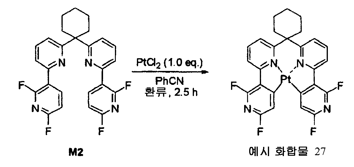
백금 클로라이드 (2.66 g, 10.0 mmol) 및 화합물 M2 (3.4 g, 7.3 mmol) 을 벤조니트릴 (70 mL) 중에서 2.5 시간 동안 가열 및 환류 조건 하에서 질소 분위기에서 교반했다. 반응 혼합물을 실온으로 냉각시켰다. 이렇게 하여 침전된 고체를 여과하고, 메탄올로 세정하여, 3.2 g 의 예시 화합물 27 을 황색 분말의 형태로 수득했다. 수율: 75%.Platinum chloride (2.66 g, 10.0 mmol) and compound M2 (3.4 g, 7.3 mmol) were heated in benzonitrile (70 mL) for 2.5 h under reflux and nitrogen atmosphere. The reaction mixture was cooled to room temperature. The precipitated solid was filtered off and washed with methanol to obtain 3.2 g of Exemplified Compound 27 in the form of a yellow powder. Yield: 75%.

[실시예 7][Example 7]
<예시 화합물 31 의 합성>≪ Synthesis of Exemplified Compound 31 >

화합물 N2 의 합성Synthesis of Compound N2
질소 분위기에서, 3 목 플라스크에 화합물 N1 (3.0 g, 6.24 mmol), 2,6-디플루오로피리딜-3-붕산 (2.38 g, 15 mmol), 팔라듐 아세테이트 (70 mg, 0.31 mmol), 트리페닐포스핀 (327 mg, 1.24 mmol), 나트륨 카르보네이트 (6.61 g, 62.4 mmol), 1,2-디메톡시에탄 (50 ml) 및 물 (50 ml) 을 충전했다. 생성된 혼합물을 환류 하에 6 시간 동안 교반하면서 가열했다. 실온으로 냉각시킨 후, 반응 혼합물을 에틸 아세테이트로 추출했다. 이와 같이 수득한 유기층을 황산 나트륨 상에서 건조시키고, 여과한 후, 농축시켰다. 수득된 잔류물을 실리카 겔 컬럼 크로마토그래피 (클로로포름) 에 의해 정제하여, 화합물 N2 를 베이지색 고체의 형태로 수득했다.In a nitrogen atmosphere, compound N1 (3.0 g, 6.24 mmol), 2,6-difluoropyridyl-3-boric acid (2.38 g, 15 mmol), palladium acetate (70 mg, 0.31 mmol) Phenyl phosphine (327 mg, 1.24 mmol), sodium carbonate (6.61 g, 62.4 mmol), 1,2-dimethoxyethane (50 ml) and water (50 ml). The resulting mixture was heated under reflux with stirring for 6 hours. After cooling to room temperature, the reaction mixture was extracted with ethyl acetate. The organic layer thus obtained was dried over sodium sulfate, filtered and concentrated. The obtained residue was purified by silica gel column chromatography (chloroform) to obtain compound N2 in the form of a beige solid.
예시 화합물 31 의 합성Synthesis of Exemplified Compound 31
질소 분위기에서, 100-mL 가지형 플라스크에 화합물 N2 (1 g, 1.82 mmol), 백금 클로라이드 (484 mg, 1.82 mmol) 및 벤조니트릴 (30 mL) 을 충전하고, 생성된 혼합물을 180 ℃ 에서 6 시간 동안 교반했다. 실온으로 냉각시킨 후, 반응 혼 합물을 50 mL 의 에탄올과 혼합하여, 고체를 침전시켰다. 이렇게 침전된 고체를 여과해 내어, 감압 하에서 건조시킴으로써, 600 mg (수율: 44%) 의 예시 화합물 31 을 황색 결정의 형태로 수득했다.Compound N2 (1 g, 1.82 mmol), platinum chloride (484 mg, 1.82 mmol) and benzonitrile (30 mL) were charged to a 100-mL eggplant type flask in a nitrogen atmosphere and the resulting mixture was stirred at 180 ≪ / RTI > After cooling to room temperature, the reaction mixture was mixed with 50 mL of ethanol to precipitate a solid. The precipitated solid was filtered out and dried under reduced pressure to obtain 600 mg (Yield: 44%) of Exemplified Compound 31 in the form of yellow crystals.

[실시예 8][Example 8]
<예시 화합물 37 의 합성>≪ Synthesis of Exemplified Compound 37 >

화합물 E2 의 합성Synthesis of Compound E2
질소 분위기에서, 화합물 E1 (700 mg, 1.35 mmol), 2,6-디플루오로피리딜-3-붕산 (2.1 g, 13.5 mmol), 팔라듐 아세테이트 (30.3 mg, 0.14 mmol), 트리페닐포스핀 (142.0 mg, 0.54 mmol), 칼륨 카르보네이트 (1.9 g, 13.5 mmol), 1,2-디메톡시에탄 (7.0 ml) 및 물 (7.0 ml) 의 혼합물을 80 ℃ 에서 8.5 시간 동안 교반했다. 실온으로 냉각시킨 후, 반응 혼합물을 여과한 후, 에틸 아세테이트로 추출했다. 이와 같이 수득한 유기층을 수거하고, 건조 후 농축시켰다. 수득된 잔류물 을 컬럼 크로마토그래피에 의해 정제하여, 501.1 mg (수율: 63%) 의 화합물 E2 를 황색 오일성 물질의 형태로 수득했다.Compound E1 (700 mg, 1.35 mmol), 2,6-difluoropyridyl-3-boric acid (2.1 g, 13.5 mmol), palladium acetate (30.3 mg, 0.14 mmol), triphenylphosphine 142.0 mg, 0.54 mmol), potassium carbonate (1.9 g, 13.5 mmol), 1,2-dimethoxyethane (7.0 ml) and water (7.0 ml) was stirred at 80 ° C for 8.5 hours. After cooling to room temperature, the reaction mixture was filtered and extracted with ethyl acetate. The organic layer thus obtained was collected, dried and concentrated. The obtained residue was purified by column chromatography to obtain 501.1 mg (Yield: 63%) of Compound E2 in the form of a yellow oily substance.

예시 화합물 37 의 합성Synthesis of Exemplified Compound 37
질소 분위기에서, 백금 클로라이드 (300 mg, 0.86 mmol) 및 화합물 E2 (501.1 mg, 0.86 mmol) 을 벤조니트릴 (10 mL) 중에서 7 시간 동안 가열 및 환류 조건 하에서 교반했다. 용매를 반응 혼합물로부터 증류 제거하고, 생성된 잔류물을 여과해 내고, 메탄올로 세정하고, 이로써 490 mg 의 백금 착물을 황색 분말의 형태로 수득했다. 수율은 73% 였다.In a nitrogen atmosphere, platinum chloride (300 mg, 0.86 mmol) and compound E2 (501.1 mg, 0.86 mmol) were heated in benzonitrile (10 mL) for 7 h and refluxed. The solvent was distilled off from the reaction mixture, the resulting residue was filtered off and washed with methanol, whereby 490 mg of platinum complex was obtained in the form of a yellow powder. The yield was 73%.

[실시예 9][Example 9]
<예시 화합물 43 의 합성>≪ Synthesis of Exemplified Compound 43 >

화합물 O2 의 합성Synthesis of Compound O2
질소 분위기에서, 3 목 플라스크에 화합물 O1 (1.25 g, 3.2 mmol), 2,6-디플루오로피리딜-3-붕산 (1.22 g, 7.68 mmol), 팔라듐 아세테이트 (71.7 mg, 0.32 mmol), 트리페닐포스핀 (340 mg, 1.28 mmol), 칼륨 카르보네이트 (5.91 g, 42.2 mmol), 테트라히드로푸란 (30 ml) 및 물 (30 ml) 를 충전했다. 생성된 혼합물을 환류 하에 6 시간 동안 교반하면서 가열했다. 실온으로 냉각시킨 후, 반응 혼합물을 에틸 아세테이트로 추출했다. 이와 같이 수득한 유기층을 황산 나트륨 상에서 건조시키고, 여과한 후, 농축시켰다. 수득된 잔류물을 실리카 겔 컬럼 크로마토그래피에 의해 정제하여, 0.94 g 의 화합물 O2 를 백색 고체의 형태로 수득했다.(1.22 g, 3.2 mmol), 2,6-difluoropyridyl-3-boric acid (1.22 g, 7.68 mmol), palladium acetate (71.7 mg, 0.32 mmol), tri Phenyl phosphine (340 mg, 1.28 mmol), potassium carbonate (5.91 g, 42.2 mmol), tetrahydrofuran (30 ml) and water (30 ml). The resulting mixture was heated under reflux with stirring for 6 hours. After cooling to room temperature, the reaction mixture was extracted with ethyl acetate. The organic layer thus obtained was dried over sodium sulfate, filtered and concentrated. The obtained residue was purified by silica gel column chromatography to obtain 0.94 g of compound O2 in the form of a white solid.
예시 화합물 43 의 합성Synthesis of Exemplified Compound 43
질소 분위기에서, 100-mL 가지형 플라스크에 화합물 O2 (450 mg, 0.98 mmol), 백금 클로라이드 (260 mg, 0.98 mmol) 및 벤조니트릴 (10 mL) 을 충전하고, 생성된 혼합물을 180 ℃ 에서 2 시간 동안 교반했다. 실온으로 냉각시킨 후, 반응 혼합물을 50 mL 의 에탄올과 혼합하여, 고체를 침전시켰다. 이렇게 침전된 고체를 여과해 내어, 감압 하에서 건조시킴으로써, 270 mg 의 예시 화합물 43 을 황색 결정의 형태로 수득했다.Compound O2 (450 mg, 0.98 mmol), platinum chloride (260 mg, 0.98 mmol) and benzonitrile (10 mL) were charged into a 100-mL eggplant type flask in a nitrogen atmosphere and the resulting mixture was stirred at 180 ≪ / RTI > After cooling to room temperature, the reaction mixture was mixed with 50 mL of ethanol to precipitate solids. The precipitated solid was filtered out and dried under reduced pressure to obtain 270 mg of Exemplified Compound 43 in the form of yellow crystals.

[실시예 10][Example 10]
<예시 화합물 46 의 합성>≪ Synthesis of Exemplified Compound 46 >

화합물 F2 의 합성Synthesis of Compound F2
질소 분위기에서, 3 목 플라스크에 화합물 F1 (0.8 g, 2.25 mmol), 2,6-디플루오로피리딜-3-붕산 (858 mg, 5.4 mmol), 팔라듐 아세테이트 (25 mg, 0.11 mmol), 트리페닐포스핀 (118 mg, 0.45 mmol), 나트륨 카르보네이트 (2.38 g, 22.5 mmol), 1,2-디메톡시에탄 (20 ml) 및 물 (20 ml) 를 충전했다. 생성된 혼합물을 환류 하에 6 시간 동안 교반하면서 가열했다. 실온으로 냉각시킨 후, 반응 혼합물을 에틸 아세테이트로 추출했다. 이와 같이 수득한 유기층을 황산 나트륨 상에서 건조시키고, 여과한 후, 농축시켰다. 수득된 잔류물을 실리카 겔 컬럼 크로마토그래피 (클로로포름) 에 의해 정제하여, 0.86 g (수율: 79%) 의 화합물 F2 를 베 이지색 고체의 형태로 수득했다.(0.8 g, 2.25 mmol), 2,6-difluoropyridyl-3-boric acid (858 mg, 5.4 mmol), palladium acetate (25 mg, 0.11 mmol), tri Phenyl phosphine (118 mg, 0.45 mmol), sodium carbonate (2.38 g, 22.5 mmol), 1,2-dimethoxyethane (20 ml) and water (20 ml). The resulting mixture was heated under reflux with stirring for 6 hours. After cooling to room temperature, the reaction mixture was extracted with ethyl acetate. The organic layer thus obtained was dried over sodium sulfate, filtered and concentrated. The resulting residue was purified by silica gel column chromatography (chloroform) to obtain 0.86 g (yield: 79%) of Compound F2 in the form of a white solid.

예시 화합물 46 의 합성Synthesis of Exemplified Compound 46
질소 분위기에서, 100-mL 가지형 플라스크에 화합물 F2 (700 mg, 1.44 mmol), 백금 클로라이드 (383 mg, 1.44 mmol) 및 벤조니트릴 (35 mL) 를 충전하고, 생성된 혼합물을 180 ℃ 에서 2 시간 동안 교반했다. 실온으로 냉각시킨 후, 반응 혼합물을 50 mL 의 메탄올과 혼합하여, 고체를 침전시켰다. 이렇게 침전된 고체를 여과해 내어, 감압 하에서 건조시킴으로써, 457 mg (수율: 48%) 의 예시 화합물 46 을 황색 결정의 형태로 수득했다.Compound F2 (700 mg, 1.44 mmol), platinum chloride (383 mg, 1.44 mmol) and benzonitrile (35 mL) were charged into a 100-mL eggplant type flask in a nitrogen atmosphere and the resulting mixture was stirred at 180 ≪ / RTI > After cooling to room temperature, the reaction mixture was mixed with 50 mL of methanol to precipitate a solid. The precipitated solid was filtered off and dried under reduced pressure to obtain 457 mg (yield: 48%) of Exemplified Compound 46 in the form of yellow crystals.

[실시예 11][Example 11]
<예시 화합물 47 의 합성>≪ Synthesis of Exemplified Compound 47 >
화합물 P2 의 합성Synthesis of Compound P2

화합물 P1(1.0 g, 2.9 mmol), 2,6-디플루오로피리딜-3-붕산 (1.4 g, 8.5 mmol), 디클로로비스(트리페닐포스핀)팔라듐(II) (200 mg, 0.94 mmol), 칼륨 카르보네이트 (2.4 g, 6.0 mmol), 물 (102 mg, 5.7 mmol) 및 디옥산 (30.0 mL) 의 혼합물을 환류 하에 4.5 시간 동안 질소 분위기에서 가열했다. 반응 혼합물을 실온으로 냉각시키고, 여과하고, 물과 혼합한 후, 에틸 아세테이트로 추출했다. 유기층을 수거하고, 건조시키고, 또한 농축시켰다. 생성된 잔류물을 컬럼 크로마토그래피에 의해 정제하여, 730 mg (수율: 50%) 의 화합물 P2 를 백색 고체의 형태로 수득했다.Dichlorobis (triphenylphosphine) palladium (II) (200 mg, 0.94 mmol) was added to a solution of the compound P1 (1.0 g, 2.9 mmol), 2,6-difluoropyridyl- , Potassium carbonate (2.4 g, 6.0 mmol), water (102 mg, 5.7 mmol) and dioxane (30.0 mL) was heated under reflux in a nitrogen atmosphere for 4.5 hours. The reaction mixture was cooled to room temperature, filtered, mixed with water and extracted with ethyl acetate. The organic layer was collected, dried and concentrated. The resultant residue was purified by column chromatography to obtain 730 mg (Yield: 50%) of compound P2 in the form of a white solid.

예시 화합물 47 의 합성Synthesis of Exemplified Compound 47

질소 분위기에서, 백금 클로라이드 (193 mg, 0.72 mmol) 및 화합물 P2 (370 mg, 0.72 mmol) 를 벤조니트릴 (7.0 mL) 중에서 3 시간 동안 가열 및 환류 조건 하에서 교반했다. 반응 혼합물을 실온으로 냉각시키고, 메탄올 첨가에 의해 침전된 고체를 여과해 내어, 메탄올로 세정했다. 이와 같이 하여, 370 mg 의 예시 화합물 47 을 밝은 황색 분말의 형태로 수득했다. 수율은 73% 였다.In a nitrogen atmosphere, platinum chloride (193 mg, 0.72 mmol) and compound P2 (370 mg, 0.72 mmol) were heated in benzonitrile (7.0 mL) for 3 hours and refluxed. The reaction mixture was cooled to room temperature, the precipitated solid was filtered off with methanol addition, and washed with methanol. In this way, 370 mg of Exemplified Compound 47 was obtained in the form of a light yellow powder. The yield was 73%.

[실시예 12][Example 12]
<예시 화합물 54 의 합성>≪ Synthesis of Exemplified Compound 54 >

화합물 12 의 합성Synthesis of Compound 12
질소 분위기에서, 3 목 플라스크에 화합물 I1 (0.95 g, 2.03 mmol), 2,6-디플루오로피리딜-3-붕산 (1.28 g, 8.12 mmol), 팔라듐 아세테이트 (23 mg, 0.11 mmol), 트리페닐포스핀 (106 mg, 0.41 mmol), 칼륨 카르보네이트 (2.80 g, 20.3 mmol), 테트라히드로푸란 (20 ml) 및 물 (10 ml) 를 충전했다. 생성된 혼합물을 환류 하에 5 시간 동안 교반하면서 가열했다. 실온으로 냉각시킨 후, 반응 혼합물을 에틸 아세테이트로 추출했다. 이와 같이 수득한 유기층을 황산 나트륨 상에서 건조시키고, 여과한 후, 농축시켰다. 수득된 잔류물을 실리카 겔 컬럼 크로마토그래피 (헥산/에틸 아세테이트=20/1) 에 의해 정제하여, 1.04 g (수율: 95%) 의 화합물 I2 를 백색 고체의 형태로 수득했다.In a nitrogen atmosphere, compound I1 (0.95 g, 2.03 mmol), 2,6-difluoropyridyl-3-boric acid (1.28 g, 8.12 mmol), palladium acetate (23 mg, 0.11 mmol) Phenyl phosphine (106 mg, 0.41 mmol), potassium carbonate (2.80 g, 20.3 mmol), tetrahydrofuran (20 ml) and water (10 ml). The resulting mixture was heated under reflux with stirring for 5 hours. After cooling to room temperature, the reaction mixture was extracted with ethyl acetate. The organic layer thus obtained was dried over sodium sulfate, filtered and concentrated. The obtained residue was purified by silica gel column chromatography (hexane / ethyl acetate = 20/1) to obtain 1.04 g (yield: 95%) of compound I2 in the form of a white solid.

예시 화합물 54 의 합성Synthesis of Exemplified Compound 54
질소 분위기에서, 100-mL 가지형 플라스크에 화합물 I2 (830 mg, 1.55 mol), 백금 클로라이드 (411 mg, 1.55 mmol) 및 벤조니트릴 (40 mL) 를 충전했다. 생성된 혼합물을 180 ℃ 에서 2 시간 동안 교반했다. 실온으로 냉각시킨 후, 50 mL 의 메탄올을 반응 혼합물에 첨가했다. 이와 같이 하여 침전된 고체를 여과하고, 감압 하에 건조시켜, 736 mg (수율: 65%) 의 예시 화합물 54 를 황색 결정의 형태로 수득했다.Compound I2 (830 mg, 1.55 mol), platinum chloride (411 mg, 1.55 mmol) and benzonitrile (40 mL) were charged into a 100-mL eggplant type flask in a nitrogen atmosphere. The resulting mixture was stirred at 180 < 0 > C for 2 hours. After cooling to room temperature, 50 mL of methanol was added to the reaction mixture. The thus precipitated solid was filtered and dried under reduced pressure to obtain 736 mg (Yield: 65%) of Exemplified Compound 54 in the form of yellow crystals.

[실시예 13][Example 13]
<예시 화합물 55 의 합성>≪ Synthesis of Exemplified Compound 55 >
화합물 G2 의 합성Synthesis of Compound G2

화합물 G1 (2.16 g, 4.0 mmol), 2,6-디플루오로피리딜-3-붕산 (1.90 g, 12.0 mmol), 팔라듐 아세테이트 (45 mg, 0.2 mmol), 트리페닐포스핀 (0.21 g, 0.8 mmol), 나트륨 카르보네이트 (4.24 g, 40.0 mmol), 1,2-디메톡시에탄 (40 mL) 및 물 (40 mL) 로 이루어지는 혼합물을 80 ℃ 에서 5 시간 동안 질소 분위기에서 교반했다. 실온으로 냉각시킨 후, 반응 혼합물을 여과한 후, 클로로포름으로 추출했다. 유기층들을 배합하고, 건조시키고 농축시켰다. 이와 같이 수득한 잔류물을 컬럼 크로마토그래피에 의해 정제하여, 2.26 g 의 화합물 G2 를 백색 결정의 형태로 수득했다. 수율: 93%.To a solution of compound G1 (2.16 g, 4.0 mmol), 2,6-difluoropyridyl-3-boric acid (1.90 g, 12.0 mmol), palladium acetate (45 mg, 0.2 mmol), triphenylphosphine mmol), sodium carbonate (4.24 g, 40.0 mmol), 1,2-dimethoxyethane (40 mL) and water (40 mL) was stirred at 80 ° C for 5 hours in a nitrogen atmosphere. After cooling to room temperature, the reaction mixture was filtered and then extracted with chloroform. The organic layers were combined, dried and concentrated. The thus-obtained residue was purified by column chromatography to obtain 2.26 g of compound G2 in the form of white crystals. Yield: 93%.

예시 화합물 55 의 합성Synthesis of Exemplified Compound 55

백금 클로라이드 (0.79 g, 3.0 mmol) 및 화합물 G2 (1.82 g, 3.0 mmol, 1.0 당량) 을 4 시간 동안 벤조니트릴 (30 mL) 중에서 가열 및 환류 조건 하에서 질소 분위기에서 교반했다. 용매를 반응 혼합물로부터 증류 제거했다. 이와 같이 수득한 잔류물을 컬럼 크로마토그래피에 의해 정제하고, 재결정화시켜, 1.8 g 의 예시 화합물 55 를 황색 분말의 형태로 수득했다. 수율: 76%.Platinum chloride (0.79 g, 3.0 mmol) and compound G2 (1.82 g, 3.0 mmol, 1.0 eq.) Were stirred in benzonitrile (30 mL) for 4 h under heating and reflux conditions under a nitrogen atmosphere. The solvent was distilled off from the reaction mixture. The thus obtained residue was purified by column chromatography and recrystallized to obtain 1.8 g of Exemplified Compound 55 in the form of a yellow powder. Yield: 76%.

[실시예 14][Example 14]
<예시 화합물 86 의 합성>≪ Synthesis of Exemplified Compound 86 >
화합물 H2 의 합성Synthesis of Compound H2

화합물 H1 (3.0 g, 5.0 mmol), 2,6-디플루오로피리딜-3-붕산 (2.4 g, 15.0 mmol), 팔라듐 아세테이트 (56.1 mg, 0.25 mmol), 트리페닐포스핀 (262.0 mg, 1.0 mmol), 나트륨 카르보네이트 (5.3 g, 50.0 mmol), 1,2-디메톡시에탄 (50 mL) 및 물 (50 mL) 로 이루어지는 혼합물을 80 ℃ 에서 5 시간 동안 질소 분위기에서 교반했다. 실온으로 냉각시킨 후, 반응 혼합물을 여과한 후, 클로로포름으로 추출했다. 유기층들을 배합하고, 건조시키고 농축시켰다. 이와 같이 수득한 잔류물을 컬럼 크로마토그래피에 의해 정제하여, 3.3 g 의 화합물 H2 를 백색 결정의 형태로 수득했다. 수율: 98%.Compound H1 (3.0 g, 5.0 mmol), 2,6-difluoropyridyl-3-boric acid (2.4 g, 15.0 mmol), palladium acetate (56.1 mg, 0.25 mmol), triphenylphosphine mmol), sodium carbonate (5.3 g, 50.0 mmol), 1,2-dimethoxyethane (50 mL) and water (50 mL) was stirred at 80 ° C for 5 hours in a nitrogen atmosphere. After cooling to room temperature, the reaction mixture was filtered and then extracted with chloroform. The organic layers were combined, dried and concentrated. The thus-obtained residue was purified by column chromatography to obtain 3.3 g of compound H2 in the form of white crystals. Yield: 98%.

예시 화합물 86 의 합성Synthesis of Exemplified Compound 86

백금 클로라이드 (1.12 g, 4.2 mmol) 및 화합물 H2 (2.80 g, 4.2 mmol, 1.0 당량) 을 4 시간 동안 벤조니트릴 (42 mL) 중에서 가열 및 환류 조건 하에서 질소 분위기에서 교반했다. 용매를 반응 혼합물로부터 증류 제거했다. 이와 같이 수득한 잔류물을 컬럼 크로마토그래피에 의해 정제하고, 재결정화시켜, 2.4 g 의 예시 화합물 86 을 황색 분말의 형태로 수득했다. 수율: 66%.Platinum chloride (1.12 g, 4.2 mmol) and compound H2 (2.80 g, 4.2 mmol, 1.0 eq.) Were stirred in benzonitrile (42 mL) for 4 hours under heating and reflux conditions under nitrogen atmosphere. The solvent was distilled off from the reaction mixture. The thus-obtained residue was purified by column chromatography and recrystallized to obtain 2.4 g of Exemplified Compound 86 in the form of a yellow powder. Yield: 66%.

[실시예 15][Example 15]
<예시 화합물 87 의 합성>≪ Synthesis of Exemplified Compound 87 >

화합물 Q2 의 합성Synthesis of Compound Q2
질소 분위기에서, 3 목 플라스크에 화합물 Q1 (1.77 g, 4.23 mmol), 2,6-디플루오로피리딜-3-붕산 (1.6 g, 10 mmol), 팔라듐 아세테이트 (48 mg, 0.22 mmol), 트리페닐포스핀 (221 mg, 0.846 mmol), 나트륨 카르보네이트 (4.48 g, 42.3 mmol), 1,2-디메톡시에탄 (25 ml) 및 물 (25 ml) 를 충전했다. 생성된 혼합물을 환류 하에 6 시간 동안 교반하면서 가열했다. 실온으로 냉각시킨 후, 반응 혼합물을 에틸 아세테이트로 추출했다. 이와 같이 수득한 유기층을 황산 나트륨 상에서 건조시키고, 여과한 후, 농축시켰다. 수득된 잔류물을 실리카 겔 컬럼 크로마토그래피에 의해 정제하여, 2.1 g 의 화합물 Q2 를 베이지색 고체의 형태로 수득했다.(1.77 g, 4.23 mmol), 2,6-difluoropyridyl-3-boric acid (1.6 g, 10 mmol), palladium acetate (48 mg, 0.22 mmol), tri Phenyl phosphine (221 mg, 0.846 mmol), sodium carbonate (4.48 g, 42.3 mmol), 1,2-dimethoxyethane (25 ml) and water (25 ml). The resulting mixture was heated under reflux with stirring for 6 hours. After cooling to room temperature, the reaction mixture was extracted with ethyl acetate. The organic layer thus obtained was dried over sodium sulfate, filtered and concentrated. The obtained residue was purified by silica gel column chromatography to obtain 2.1 g of compound Q2 in the form of a beige solid.
예시 화합물 87 의 합성Synthesis of Exemplified Compound 87
질소 분위기에서, 100-mL 가지형 플라스크에 화합물 Q2 (2.1 g, 4.31 mmol), 백금 클로라이드 (1.148 g, 4.31 mmol) 및 벤조니트릴 (30 mL) 를 충전하고, 생성된 혼합물을 180 ℃ 에서 2 시간 동안 교반했다. 실온으로 냉각시킨 후, 반응 혼합물을 50 mL 의 메탄올과 혼합하여, 고체를 침전시켰다. 이렇게 침전된 고체를 여과해 내어, 감압 하에서 건조시킴으로써, 1.52 g (수율: 52%) 의 예시 화합물 87 을 황색 결정의 형태로 수득했다.Compound Q2 (2.1 g, 4.31 mmol), platinum chloride (1.148 g, 4.31 mmol) and benzonitrile (30 mL) were charged to a 100-mL eggplant type flask in a nitrogen atmosphere and the resulting mixture was stirred at 180 ≪ / RTI > After cooling to room temperature, the reaction mixture was mixed with 50 mL of methanol to precipitate a solid. The precipitated solid was filtered off and dried under reduced pressure to give 1.52 g (yield: 52%) of the exemplified compound 87 in the form of yellow crystals.

[실시예 16][Example 16]
<예시 화합물 96 의 합성>≪ Synthesis of Exemplified Compound 96 >

화합물 O1 대신 원료 재료로서 화합물 R1 을 사용한 것을 제외하고는 예시 화합물 43 의 합성에서 사용한 바와 동일한 방법에 의해 예시 화합물 96 의 합성을 수행하여, 예시 화합물 96 을 황색 결정의 형태로 수득했다. Exemplified Compound 96 was synthesized in the same manner as in the synthesis of Exemplified Compound 43, except that Compound R1 was used as a raw material in place of Compound O1 to obtain Exemplified Compound 96 in the form of yellow crystals.

[실시예 17][Example 17]
<예시 화합물 97 의 합성>≪ Synthesis of Exemplified Compound 97 >

화합물 S2 의 합성Synthesis of Compound S2
질소 분위기에서, 3 목 플라스크에 화합물 A1 (2.0 g, 5.62 mmol), 2,6-디메 톡시피리딜-3-붕산 (2.41 g, 13.5 mmol), 팔라듐 아세테이트 (63 mg, 0.28 mmol), 트리페닐포스핀 (294 mg, 1.12 mmol), 나트륨 카르보네이트 (5.96 g, 56.2 mmol), 1,2-디메톡시에탄 (40 ml) 및 물 (40 ml) 을 충전해다. 생성된 혼합물을 환류 하에 4 시간 동안 교반하면서 가열했다. 실온으로 냉각시킨 후, 반응 혼합물을 에틸 아세테이트로 추출했다. 이와 같이 수득한 유기층을 황산 나트륨 상에서 건조시키고, 여과한 후, 농축시켰다. 수득된 잔류물을 실리카 겔 컬럼 크로마토그래피에 의해 정제하여, 2.25 g 의 화합물 S2 를 베이지색 고체의 형태로 수득했다.(2.0 g, 5.62 mmol), 2,6-dimethoxypyridyl-3-boric acid (2.41 g, 13.5 mmol), palladium acetate (63 mg, 0.28 mmol), triphenyl (294 mg, 1.12 mmol), sodium carbonate (5.96 g, 56.2 mmol), 1,2-dimethoxyethane (40 ml) and water (40 ml). The resulting mixture was heated under reflux with stirring for 4 hours. After cooling to room temperature, the reaction mixture was extracted with ethyl acetate. The organic layer thus obtained was dried over sodium sulfate, filtered and concentrated. The obtained residue was purified by silica gel column chromatography to obtain 2.25 g of compound S2 in the form of a beige solid.
예시 화합물 97 의 합성Synthesis of Exemplified Compound 97
질소 분위기에서, 100-mL 가지형 플라스크에 화합물 S2 (2.05 g, 4.34 mmol), K2PtCl4 (1.8 g, 4.34 mmol) 및 아세트산 (50 mL) 를 충전하고, 생성된 혼합물을 100 ℃ 에서 8 시간 동안 교반했다. 실온으로 냉각시킨 후, 반응 혼합물을 물과 혼합하고, 클로로포름으로 추출했다. 수득된 유기층을 황산 나트륨 상에서 건조시키고, 여과하고, 이후 농축시켰다. 이와 같이 수득한 잔류물을 실리카 겔 컬럼 크로마토그래피에 의해 정제함으로써, 0.38 g 의 예시 화합물 97 을 황색 결정의 형태로 수득했다.Compound 2.0 (2.05 g, 4.34 mmol), K 2 PtCl 4 (1.8 g, 4.34 mmol) and acetic acid (50 mL) were charged into a 100-mL eggplant type flask in a nitrogen atmosphere, Lt; / RTI > After cooling to room temperature, the reaction mixture was mixed with water and extracted with chloroform. The resulting organic layer was dried over sodium sulfate, filtered and then concentrated. The thus obtained residue was purified by silica gel column chromatography to obtain 0.38 g of Exemplified Compound 97 in the form of yellow crystals.

[비교예 1][Comparative Example 1]
국제 특허 공보 2004-108857 에 개시된 화합물 55 의 리간드 C2 및 리간드 D2 (이의 각각은 백금-탄소 결합을 형성하는 각각의 피리딘 고리의 α-위치에 치환기를 갖지 않음) 를 합성했고, 이의 각각을 실시예 1 및 2 와 동일한 방법에 의해 착물화반응시켰다. 그러나, 모든 경우, 부산물이 다량으로 형성되었고, 목적 착물의 수율은 1 % 이하였다.Ligand C2 and ligand D2 of compound 55 disclosed in International Patent Publication 2004-108857 (each of which has no substituent at the? -Position of each pyridine ring forming a platinum-carbon bond) were synthesized, 1 and 2, respectively. However, in all cases, by-products were formed in large amounts, and the yield of the target complex was 1% or less.

[실시예 18][Example 18]
세정한 ITO 기판을 진공 증착 장치에 넣고, 그 기판 상에 구리 프탈로시아닌을 10 nm 의 두께로 증착했다. 그 위에 NPD ((N,N'-디-α-나프틸-N,N'-디페닐)-벤지딘) 을 40 nm 의 두께로 증착했다. 그 위에 mCP (호스트 재료) 및 예시 화합물 3 을 85:15 의 비율 (질량비) 로 67 nm 의 두께로 증착하고, 그 위에 BAlq 를 40 nm 의 두께로 증착했다. 그 위에 3 nm 의 두께로 리튬 플루오라이드를 증착하고, 그 위에 60 nm 의 두께로 알루미늄을 증착했다. 이러한 식으로, EL 소자를 제작했다. Source-Measure Unit Model 2400 (Toyo Corporation 사제) 를 통해 EL 소자에 일정 직류 전압을 인가하여, 발광을 유도했을 때, 방출된 광은 예시 화합물 3 에서 유래된 청색광이었다. 소자를 360 cd/m2 (발광 면적: 4 mm2) 로 구동했을 때 이 소자의 휘도 반감기가 (휘도가 최초 휘도의 50 % 로 감소하는데 걸리는 시간) 비교예 2 의 소자의 휘도 반감기보다 1.05 배 길었다. 반면, 소자를 1,000 cd/m2 (발광 면적: 4 mm2) 의 한층 더 고휘도 조건 하에서 구동한했을 때, 이 소자의 휘도 반감기는 비교예 2 의 소자의 휘도 반감기보다 1.8 배 길었다.The cleaned ITO substrate was placed in a vacuum deposition apparatus, and copper phthalocyanine was deposited to a thickness of 10 nm on the substrate. NPD ((N, N'-di- alpha -naphthyl-N, N'-diphenyl) -benzidine) was deposited thereon to a thickness of 40 nm. MCP (host material) and Exemplary Compound 3 were deposited thereon in a ratio of 85: 15 (mass ratio) to a thickness of 67 nm, and BAlq was deposited thereon to a thickness of 40 nm. Lithium fluoride was deposited thereon to a thickness of 3 nm, and aluminum was deposited thereon to a thickness of 60 nm. In this way, an EL element was produced. When light emission was induced by applying a constant direct current voltage to the EL element through the Source-Measure Unit Model 2400 (manufactured by Toyo Corporation), the emitted light was blue light derived from Exemplified Compound 3. [ When the device was driven at 360 cd / m 2 (emission area: 4 mm 2 ), the luminance half-life of this device (time taken for the luminance to decrease to 50% of the initial luminance) was 1.05 times It was long. On the other hand, when the device was driven under a further high luminance condition of 1,000 cd / m 2 (light emitting area: 4 mm 2 ), the luminance half-life of this device was 1.8 times longer than the luminance half-life of the device of Comparative Example 2.
[실시예 19] 내지 [실시예 27][Examples 19 to 27]
각각의 발광층 내에 호스트 재료 및 발광 재료로서 표 1 에 나타낸 재료를 사용한 것 이외에는 실시예 18 과 동일한 방법으로 EL 소자를 제작했고, 소자를 360 cd/m2 (발광 면적: 4 mm2) 및 1,000 cd/m2 (발광 면적: 4 mm2) 으로 각각 구동하는 조건 하에서의 각 소자의 휘도 반감기를 측정했다. 얻어진 결과를 표 1 에 나타냈다.An EL device was fabricated in the same manner as in Example 18 except that the materials shown in Table 1 were used as the host material and the luminescent material in each luminescent layer. The EL device was manufactured at 360 cd / m 2 (light emitting area: 4 mm 2 ) / m < 2 > (light emission area: 4 mm < 2 >), respectively. The obtained results are shown in Table 1.
[표 1][Table 1]
(360 cd/m2 으로 구동시),
비교예 2 에 대한 상대값으로 표시
(비교예 2 를 1 로 함)Luminance half-life
(When driven at 360 cd / m < 2 >),
Relative value for Comparative Example 2
(Comparative Example 2 is referred to as 1)
(1000 cd/m2 으로 구동시),
비교예 2 에 대한 상대값으로 표시
(비교예 2 를 1 로 함)Luminance half-life
(When driven at 1000 cd / m < 2 >),
Relative value for Comparative Example 2
(Comparative Example 2 is referred to as 1)
[비교예 2][Comparative Example 2]
세정한 ITO 기판을 진공 증착 장치에 넣고, 그 기판 상에 구리 프탈로시아닌을 10 nm 의 두께로 증착했다. 그 위에 NPD ((N,N'-디-α-나프틸-N,N'-디페닐)-벤지딘) 을 40 nm 의 두께로 증착했다. 그 위에 mCP (호스트 재료) 및 JP-A-2007-19462 에 기재된 화합물 2 를 85:15 의 비율 (질량비) 로 67 nm 의 두께로 증착하고, 그 위에 BAlq 를 40 nm 의 두께로 증착했다. 그 위에 3 nm 의 두께로 리튬 플루오라이드를 증착하고, 그 위에 60 nm 의 두께로 알루미늄을 증착했다. 이러한 식으로, EL 소자를 제작했다. Source-Measure Unit Model 2400 (Toyo Corporation 사제) 를 통해 EL 소자에 일정 직류 전압을 인가하여, 발광을 유도했을 때, 방출된 광은 화합물 2 에서 유래된 청색광이었다. 소자를 360 cd/m2 (발광 면적: 4 mm2) 로 구동했을 때 이 소자의 휘도 반감기가 100 시간이었던 반면, 소자를 1,000 cd/m2 (발광 면적: 4 mm2) 의 한층 더 고휘도 조건 하에서 구동했을 때, 35 시간이었다.The cleaned ITO substrate was placed in a vacuum deposition apparatus, and copper phthalocyanine was deposited to a thickness of 10 nm on the substrate. NPD ((N, N'-di- alpha -naphthyl-N, N'-diphenyl) -benzidine) was deposited thereon to a thickness of 40 nm. MCP (host material) and compound 2 described in JP-A-2007-19462 were deposited in a ratio of 85:15 (mass ratio) to a thickness of 67 nm, and BAlq was deposited thereon to a thickness of 40 nm. Lithium fluoride was deposited thereon to a thickness of 3 nm, and aluminum was deposited thereon to a thickness of 60 nm. In this way, an EL element was produced. When a constant direct current voltage was applied to the EL element through Source-Measure Unit Model 2400 (manufactured by Toyo Corporation) to induce luminescence, the emitted light was blue light derived from compound 2. [ When the device was driven at 360 cd / m 2 (emission area: 4 mm 2 ), the half-life of the device was 100 hours, while the device was operated at a higher luminance condition of 1,000 cd / m 2 (emission area: 4 mm 2 ) , It was 35 hours.
구리 프탈로시아닌, NPD, JP-A-2007-19462 에 기재된 화합물 2, mCP, 호스트 1 및 BAlq 의 화학 구조는 다음과 같다.The chemical structures of copper phthalocyanine, NPD, compound 2, mCP, host 1 and BAlq described in JP-A-2007-19462 are as follows.

본 발명의 또다른 백금 착물을 이용하여 수득한 유기 전계 발광 소자 또한 고휘도 소자로서 이용시에도 뛰어난 내구성을 보였다.The organic electroluminescent device obtained using another platinum complex of the present invention also exhibited excellent durability even when used as a high-brightness device.
본 출원에서 그 외국 우선권의 권리가 주장되는 모든 외국 특허 출원의 전체 개시는 본원에 참고로서 삽입된다.The entire disclosure of which is hereby incorporated by reference in its entirety.
Claims (6)


Applications Claiming Priority (6)
| Application Number | Priority Date | Filing Date | Title |
|---|---|---|---|
| JPJP-P-2007-00239652 | 2007-09-14 | ||
| JP2007239652 | 2007-09-14 | ||
| JPJP-P-2007-00329145 | 2007-12-20 | ||
| JP2007329145 | 2007-12-20 | ||
| JPJP-P-2008-00194095 | 2008-07-28 | ||
| JP2008194095A JP4579320B2 (en) | 2007-09-14 | 2008-07-28 | Organic electroluminescence device |
Publications (2)
| Publication Number | Publication Date |
|---|---|
| KR20090028437A KR20090028437A (en) | 2009-03-18 |
| KR101548382B1 true KR101548382B1 (en) | 2015-08-28 |
Family
ID=40011275
Family Applications (1)
| Application Number | Title | Priority Date | Filing Date |
|---|---|---|---|
| KR1020080089432A KR101548382B1 (en) | 2007-09-14 | 2008-09-10 | Organic electroluminescence device |
Country Status (3)
| Country | Link |
|---|---|
| US (1) | US8187729B2 (en) |
| EP (1) | EP2036907B1 (en) |
| KR (1) | KR101548382B1 (en) |
Families Citing this family (48)
| Publication number | Priority date | Publication date | Assignee | Title |
|---|---|---|---|---|
| EP3211057B2 (en) * | 2003-06-02 | 2022-11-02 | UDC Ireland Limited | Organic electroluminescent devices and metal complex compounds |
| JP4531836B2 (en) * | 2008-04-22 | 2010-08-25 | 富士フイルム株式会社 | Organic electroluminescent device, novel platinum complex compound and novel compound that can be a ligand |
| JP4531842B2 (en) * | 2008-04-24 | 2010-08-25 | 富士フイルム株式会社 | Organic electroluminescence device |
| EP2417217B1 (en) | 2009-04-06 | 2017-11-22 | Arizona Board of Regents, acting for and on behalf of Arizona State University | Synthesis of four coordinated platinum complexes and their applications in light emitting devices thereof |
| JP5610848B2 (en) * | 2009-06-11 | 2014-10-22 | ユー・ディー・シー アイルランド リミテッド | Organic electroluminescence device |
| EP2550691A1 (en) | 2010-03-23 | 2013-01-30 | Merck Patent GmbH | Materials for organic electroluminescent devices |
| US9324957B2 (en) | 2010-04-30 | 2016-04-26 | Arizona Board Of Regents On Behalf Of Arizona State University | Synthesis of four coordinated gold complexes and their applications in light emitting devices thereof |
| WO2011137429A2 (en) | 2010-04-30 | 2011-11-03 | Arizona Board Of Regents Acting For And On Behalf Of Arizona State University | Synthesis of four coordinated palladium complexes and their applications in light emitting devices thereof |
| WO2012069170A1 (en) | 2010-11-22 | 2012-05-31 | Solvay Sa | A metal complex comprising a ligand having a combination of donor-acceptor substituents |
| TWI541247B (en) | 2011-02-18 | 2016-07-11 | 美國亞利桑那州立大學董事會 | Four coordinated platinum and palladium complexes with geometrically distorted charge transfer state and their applications in light emitting devices |
| US9238668B2 (en) | 2011-05-26 | 2016-01-19 | Arizona Board Of Regents, Acting For And On Behalf Of Arizona State University | Synthesis of platinum and palladium complexes as narrow-band phosphorescent emitters for full color displays |
| KR101647160B1 (en) * | 2011-12-01 | 2016-08-10 | 삼성디스플레이 주식회사 | Organic light emitting device having improved light emitting quality by reducing leakage current between pixels |
| US8987451B2 (en) * | 2012-01-03 | 2015-03-24 | Universal Display Corporation | Synthesis of cyclometallated platinum(II) complexes |
| WO2014031977A1 (en) | 2012-08-24 | 2014-02-27 | Arizona Board Of Regents For And On Behalf Of Arizona State University | Metal compounds and methods and uses thereof |
| KR102124227B1 (en) | 2012-09-24 | 2020-06-17 | 아리조나 보드 오브 리젠츠 온 비하프 오브 아리조나 스테이트 유니버시티 | Metal compounds, methods, and uses thereof |
| WO2014109814A2 (en) | 2012-10-26 | 2014-07-17 | Arizona Board Of Regents Acting For And On Behalf Of Arizona State University | Metal complexes, methods, and uses thereof |
| CN104232076B (en) | 2013-06-10 | 2019-01-15 | 代表亚利桑那大学的亚利桑那校董会 | Four tooth metal complex of phosphorescence with improved emission spectrum |
| JP6804823B2 (en) | 2013-10-14 | 2020-12-23 | アリゾナ・ボード・オブ・リージェンツ・オン・ビハーフ・オブ・アリゾナ・ステイト・ユニバーシティーArizona Board of Regents on behalf of Arizona State University | Platinum complex and device |
| US9224963B2 (en) | 2013-12-09 | 2015-12-29 | Arizona Board Of Regents On Behalf Of Arizona State University | Stable emitters |
| US10020455B2 (en) | 2014-01-07 | 2018-07-10 | Arizona Board Of Regents On Behalf Of Arizona State University | Tetradentate platinum and palladium complex emitters containing phenyl-pyrazole and its analogues |
| WO2015131158A1 (en) * | 2014-02-28 | 2015-09-03 | Arizona Board Of Regents On Behalf Of Arizona State University | Chiral metal complexes as emitters for organic polarized electroluminescent devices |
| US9941479B2 (en) | 2014-06-02 | 2018-04-10 | Arizona Board Of Regents On Behalf Of Arizona State University | Tetradentate cyclometalated platinum complexes containing 9,10-dihydroacridine and its analogues |
| US9923155B2 (en) | 2014-07-24 | 2018-03-20 | Arizona Board Of Regents On Behalf Of Arizona State University | Tetradentate platinum (II) complexes cyclometalated with functionalized phenyl carbene ligands and their analogues |
| US9502671B2 (en) | 2014-07-28 | 2016-11-22 | Arizona Board Of Regents On Behalf Of Arizona State University | Tridentate cyclometalated metal complexes with six-membered coordination rings |
| US9818959B2 (en) | 2014-07-29 | 2017-11-14 | Arizona Board of Regents on behlaf of Arizona State University | Metal-assisted delayed fluorescent emitters containing tridentate ligands |
| US10793546B2 (en) | 2014-08-15 | 2020-10-06 | Arizona Board Of Regents On Behalf Of Arizona State University | Non-platinum metal complexes for excimer based single dopant white organic light emitting diodes |
| WO2016029186A1 (en) | 2014-08-22 | 2016-02-25 | Arizona Board Of Regents On Behalf Of Arizona State University | Metal-assisted delayed fluorescent materials as co-host materials for fluorescent oleds |
| US11329244B2 (en) | 2014-08-22 | 2022-05-10 | Arizona Board Of Regents On Behalf Of Arizona State University | Organic light-emitting diodes with fluorescent and phosphorescent emitters |
| US9865825B2 (en) | 2014-11-10 | 2018-01-09 | Arizona Board Of Regents On Behalf Of Arizona State University | Emitters based on octahedral metal complexes |
| US10033003B2 (en) | 2014-11-10 | 2018-07-24 | Arizona Board Of Regents On Behalf Of Arizona State University | Tetradentate metal complexes with carbon group bridging ligands |
| US9711739B2 (en) | 2015-06-02 | 2017-07-18 | Arizona Board Of Regents On Behalf Of Arizona State University | Tetradentate metal complexes containing indoloacridine and its analogues |
| US9879039B2 (en) | 2015-06-03 | 2018-01-30 | Arizona Board Of Regents On Behalf Of Arizona State University | Tetradentate and octahedral metal complexes containing naphthyridinocarbazole and its analogues |
| US11930662B2 (en) | 2015-06-04 | 2024-03-12 | Arizona Board Of Regents On Behalf Of Arizona State University | Transparent electroluminescent devices with controlled one-side emissive displays |
| US10158091B2 (en) | 2015-08-04 | 2018-12-18 | Arizona Board Of Regents On Behalf Of Arizona State University | Tetradentate platinum (II) and palladium (II) complexes, devices, and uses thereof |
| US11335865B2 (en) | 2016-04-15 | 2022-05-17 | Arizona Board Of Regents On Behalf Of Arizona State University | OLED with multi-emissive material layer |
| US10177323B2 (en) | 2016-08-22 | 2019-01-08 | Arizona Board Of Regents On Behalf Of Arizona State University | Tetradentate platinum (II) and palladium (II) complexes and octahedral iridium complexes employing azepine functional groups and their analogues |
| US10822363B2 (en) | 2016-10-12 | 2020-11-03 | Arizona Board Of Regents On Behalf Of Arizona State University | Narrow band red phosphorescent tetradentate platinum (II) complexes |
| US11183670B2 (en) | 2016-12-16 | 2021-11-23 | Arizona Board Of Regents On Behalf Of Arizona State University | Organic light emitting diode with split emissive layer |
| WO2018140765A1 (en) | 2017-01-27 | 2018-08-02 | Jian Li | Metal-assisted delayed fluorescent emitters employing pyrido-pyrrolo-acridine and analogues |
| US11101435B2 (en) | 2017-05-19 | 2021-08-24 | Arizona Board Of Regents On Behalf Of Arizona State University | Tetradentate platinum and palladium complexes based on biscarbazole and analogues |
| US10516117B2 (en) | 2017-05-19 | 2019-12-24 | Arizona Board Of Regents On Behalf Of Arizona State University | Metal-assisted delayed fluorescent emttters employing benzo-imidazo-phenanthridine and analogues |
| KR102606281B1 (en) | 2017-07-14 | 2023-11-27 | 삼성디스플레이 주식회사 | Organometallic compound and organic light-emitting device including the same |
| KR20200065064A (en) | 2017-10-17 | 2020-06-08 | 지안 리 | Phosphorescent excimer with desirable molecular orientation, as a monochromatic emitter for display and lighting applications |
| US11647643B2 (en) | 2017-10-17 | 2023-05-09 | Arizona Board Of Regents On Behalf Of Arizona State University | Hole-blocking materials for organic light emitting diodes |
| US11878988B2 (en) | 2019-01-24 | 2024-01-23 | Arizona Board Of Regents On Behalf Of Arizona State University | Blue phosphorescent emitters employing functionalized imidazophenthridine and analogues |
| US11594691B2 (en) | 2019-01-25 | 2023-02-28 | Arizona Board Of Regents On Behalf Of Arizona State University | Light outcoupling efficiency of phosphorescent OLEDs by mixing horizontally aligned fluorescent emitters |
| US11785838B2 (en) | 2019-10-02 | 2023-10-10 | Arizona Board Of Regents On Behalf Of Arizona State University | Green and red organic light-emitting diodes employing excimer emitters |
| US11945985B2 (en) | 2020-05-19 | 2024-04-02 | Arizona Board Of Regents On Behalf Of Arizona State University | Metal assisted delayed fluorescent emitters for organic light-emitting diodes |
Citations (3)
| Publication number | Priority date | Publication date | Assignee | Title |
|---|---|---|---|---|
| WO2004108857A1 (en) | 2003-06-02 | 2004-12-16 | Fuji Photo Film Co., Ltd. | Organic electroluminescent devices and metal complex compounds |
| WO2005042550A1 (en) | 2003-10-30 | 2005-05-12 | Merck Patent Gmbh | Metal complexes with bipodal ligands |
| EP1683804B1 (en) | 2003-11-04 | 2013-07-31 | Takasago International Corporation | Platinum complex and luminescent element |
Family Cites Families (99)
| Publication number | Priority date | Publication date | Assignee | Title |
|---|---|---|---|---|
| US4885211A (en) | 1987-02-11 | 1989-12-05 | Eastman Kodak Company | Electroluminescent device with improved cathode |
| US4996523A (en) | 1988-10-20 | 1991-02-26 | Eastman Kodak Company | Electroluminescent storage display with improved intensity driver circuits |
| JPH0791467B2 (en) | 1990-08-29 | 1995-10-04 | 信越化学工業株式会社 | Fatigue durability silicone rubber composition and cured product |
| JP2780880B2 (en) | 1990-11-28 | 1998-07-30 | 出光興産株式会社 | Organic electroluminescence element and light emitting device using the element |
| JP3236332B2 (en) | 1991-01-29 | 2001-12-10 | パイオニア株式会社 | Organic electroluminescence device |
| JP2891783B2 (en) | 1991-02-06 | 1999-05-17 | パイオニア株式会社 | Organic electroluminescence device |
| JP2784615B2 (en) | 1991-10-16 | 1998-08-06 | 株式会社半導体エネルギー研究所 | Electro-optical display device and driving method thereof |
| JPH06212153A (en) | 1993-01-14 | 1994-08-02 | Toyo Ink Mfg Co Ltd | Organic electroluminescent element |
| JP3063453B2 (en) | 1993-04-16 | 2000-07-12 | 凸版印刷株式会社 | Driving method of organic thin film EL element |
| JPH07134558A (en) | 1993-11-08 | 1995-05-23 | Idemitsu Kosan Co Ltd | Organic electroluminescent display device |
| US5550066A (en) | 1994-12-14 | 1996-08-27 | Eastman Kodak Company | Method of fabricating a TFT-EL pixel |
| US6137467A (en) | 1995-01-03 | 2000-10-24 | Xerox Corporation | Optically sensitive electric paper |
| GB9601603D0 (en) | 1996-01-26 | 1996-03-27 | Isis Innovations Ltd | Terpyridine-platinum (II) complexes |
| JP3195265B2 (en) | 1997-01-18 | 2001-08-06 | 東京応化工業株式会社 | Coating solution for forming Bi-based ferroelectric thin film, ferroelectric thin film formed using the same, and ferroelectric memory |
| US6337492B1 (en) | 1997-07-11 | 2002-01-08 | Emagin Corporation | Serially-connected organic light emitting diode stack having conductors sandwiching each light emitting layer |
| JPH11111463A (en) | 1997-09-30 | 1999-04-23 | Sumitomo Chem Co Ltd | Organic elelctroluminescent element |
| US6303238B1 (en) | 1997-12-01 | 2001-10-16 | The Trustees Of Princeton University | OLEDs doped with phosphorescent compounds |
| JPH11251067A (en) | 1998-03-02 | 1999-09-17 | Junji Kido | Organic electroluminescence element |
| JP3884564B2 (en) | 1998-05-20 | 2007-02-21 | 出光興産株式会社 | Organic EL light emitting device and light emitting device using the same |
| DE19829948A1 (en) | 1998-07-04 | 2000-01-05 | Bayer Ag | Electroluminescent device using azomethine metal complexes |
| US6097147A (en) | 1998-09-14 | 2000-08-01 | The Trustees Of Princeton University | Structure for high efficiency electroluminescent device |
| JP2000196140A (en) | 1998-12-28 | 2000-07-14 | Sharp Corp | Organic electroluminescence element and fabrication thereof |
| EP3076759A1 (en) | 1999-03-23 | 2016-10-05 | The University Of Southern California | Cyclometallated metal complexes as phosphorescent dopants in organic leds |
| JP4408477B2 (en) | 1999-04-01 | 2010-02-03 | 大日本印刷株式会社 | EL element |
| JP4420486B2 (en) | 1999-04-30 | 2010-02-24 | 出光興産株式会社 | Organic electroluminescence device and method for producing the same |
| CN101312235B (en) | 1999-05-13 | 2010-06-09 | 普林斯顿大学理事会 | Very high efficiency organic light emitting devices based on electrophosphorescence |
| DE19931818A1 (en) | 1999-07-08 | 2001-01-11 | Maxon Motor Gmbh | Multi-stage spur gear |
| US6310360B1 (en) | 1999-07-21 | 2001-10-30 | The Trustees Of Princeton University | Intersystem crossing agents for efficient utilization of excitons in organic light emitting devices |
| JP4729154B2 (en) | 1999-09-29 | 2011-07-20 | 淳二 城戸 | Organic electroluminescent device, organic electroluminescent device group, and method for controlling emission spectrum thereof |
| US6458475B1 (en) | 1999-11-24 | 2002-10-01 | The Trustee Of Princeton University | Organic light emitting diode having a blue phosphorescent molecule as an emitter |
| JP4407776B2 (en) | 1999-12-02 | 2010-02-03 | 淳二 城戸 | Electroluminescent device |
| JP3929690B2 (en) | 1999-12-27 | 2007-06-13 | 富士フイルム株式会社 | Light emitting device material, light emitting device and novel iridium complex comprising orthometalated iridium complex |
| JP3929706B2 (en) | 2000-02-10 | 2007-06-13 | 富士フイルム株式会社 | Light emitting device material and light emitting device comprising iridium complex |
| JP2001298470A (en) | 2000-04-11 | 2001-10-26 | Dx Antenna Co Ltd | Data transmission system |
| JP4144192B2 (en) | 2000-05-29 | 2008-09-03 | 三菱化学株式会社 | Method for manufacturing organic electroluminescent device |
| JP4504512B2 (en) | 2000-05-30 | 2010-07-14 | 三井化学株式会社 | Organic electroluminescence device |
| US20020121638A1 (en) | 2000-06-30 | 2002-09-05 | Vladimir Grushin | Electroluminescent iridium compounds with fluorinated phenylpyridines, phenylpyrimidines, and phenylquinolines and devices made with such compounds |
| JP4340401B2 (en) | 2000-07-17 | 2009-10-07 | 富士フイルム株式会社 | Light emitting device and iridium complex |
| JP4712232B2 (en) | 2000-07-17 | 2011-06-29 | 富士フイルム株式会社 | Light emitting device and azole compound |
| EP2566302B1 (en) | 2000-08-11 | 2015-12-16 | The Trustees of Princeton University | Organometallic compounds and emission-shifting organic electrophosphorence |
| JP4067286B2 (en) | 2000-09-21 | 2008-03-26 | 富士フイルム株式会社 | Light emitting device and iridium complex |
| JP4505162B2 (en) | 2000-09-21 | 2010-07-21 | 富士フイルム株式会社 | Light emitting device and novel rhenium complex |
| JP4154140B2 (en) | 2000-09-26 | 2008-09-24 | キヤノン株式会社 | Metal coordination compounds |
| JP4086498B2 (en) | 2000-11-29 | 2008-05-14 | キヤノン株式会社 | Metal coordination compound, light emitting device and display device |
| JP4086499B2 (en) | 2000-11-29 | 2008-05-14 | キヤノン株式会社 | Metal coordination compound, light emitting device and display device |
| KR100825183B1 (en) | 2000-11-30 | 2008-04-24 | 캐논 가부시끼가이샤 | Luminescent Element and Display |
| JP4154145B2 (en) | 2000-12-01 | 2008-09-24 | キヤノン株式会社 | Metal coordination compound, light emitting device and display device |
| JP2002203678A (en) | 2000-12-27 | 2002-07-19 | Fuji Photo Film Co Ltd | Light-emitting element |
| JP2002203679A (en) | 2000-12-27 | 2002-07-19 | Fuji Photo Film Co Ltd | Light-emitting element |
| JP3812730B2 (en) | 2001-02-01 | 2006-08-23 | 富士写真フイルム株式会社 | Transition metal complex and light emitting device |
| JP3988915B2 (en) | 2001-02-09 | 2007-10-10 | 富士フイルム株式会社 | Transition metal complex, light emitting device material comprising the same, and light emitting device |
| JP3972588B2 (en) | 2001-02-26 | 2007-09-05 | 淳二 城戸 | Organic electroluminescence device |
| TWI243197B (en) | 2001-03-08 | 2005-11-11 | Univ Hong Kong | Organometallic light-emitting material |
| JP2002305083A (en) | 2001-04-04 | 2002-10-18 | Mitsubishi Chemicals Corp | Organic electroluminescent element |
| JP4611578B2 (en) | 2001-07-26 | 2011-01-12 | 淳二 城戸 | Organic electroluminescent device |
| JP2003123982A (en) | 2001-08-07 | 2003-04-25 | Fuji Photo Film Co Ltd | Light emitting element and novel iridium complex |
| JP4584506B2 (en) | 2001-08-28 | 2010-11-24 | パナソニック電工株式会社 | Organic electroluminescence device |
| JP3840085B2 (en) | 2001-10-09 | 2006-11-01 | キヤノン株式会社 | Organic light emitting device |
| JP2003123981A (en) | 2001-10-12 | 2003-04-25 | Canon Inc | Organic light emitting element |
| JP3835263B2 (en) | 2001-11-22 | 2006-10-18 | 株式会社豊田自動織機 | Method for forming electron-accepting dopant layer for organic electroluminescence display panel and method for producing organic electroluminescence display panel |
| JP3742054B2 (en) | 2001-11-30 | 2006-02-01 | 株式会社半導体エネルギー研究所 | Display device |
| JP2003217862A (en) | 2002-01-18 | 2003-07-31 | Honda Motor Co Ltd | Organic electroluminescent element |
| US6872472B2 (en) | 2002-02-15 | 2005-03-29 | Eastman Kodak Company | Providing an organic electroluminescent device having stacked electroluminescent units |
| JP3933591B2 (en) | 2002-03-26 | 2007-06-20 | 淳二 城戸 | Organic electroluminescent device |
| US6653654B1 (en) | 2002-05-01 | 2003-11-25 | The University Of Hong Kong | Electroluminescent materials |
| WO2004039914A1 (en) | 2002-11-01 | 2004-05-13 | Takasago International Corporation | Luminescents |
| JP4524093B2 (en) | 2002-12-17 | 2010-08-11 | 富士フイルム株式会社 | Organic electroluminescence device |
| JP2004331508A (en) | 2003-04-30 | 2004-11-25 | Takasago Internatl Corp | Platinum complex |
| US6936961B2 (en) | 2003-05-13 | 2005-08-30 | Eastman Kodak Company | Cascaded organic electroluminescent device having connecting units with N-type and P-type organic layers |
| JP2004357791A (en) | 2003-06-02 | 2004-12-24 | Sea Shell:Kk | Footwear |
| JP4460952B2 (en) | 2003-06-02 | 2010-05-12 | 富士フイルム株式会社 | Organic electroluminescent device and complex compound |
| DE10338550A1 (en) | 2003-08-19 | 2005-03-31 | Basf Ag | Transition metal complexes with carbene ligands as emitters for organic light-emitting diodes (OLEDs) |
| DE10339772B4 (en) | 2003-08-27 | 2006-07-13 | Novaled Gmbh | Light emitting device and method for its production |
| JP4243237B2 (en) | 2003-11-10 | 2009-03-25 | 淳二 城戸 | Organic element, organic EL element, organic solar cell, organic FET structure, and organic element manufacturing method |
| JP5137292B2 (en) | 2003-12-26 | 2013-02-06 | 株式会社半導体エネルギー研究所 | LIGHT EMITTING ELEMENT, LIGHT EMITTING DEVICE, AND ELECTRIC APPARATUS |
| KR100537621B1 (en) | 2004-02-02 | 2005-12-19 | 삼성에스디아이 주식회사 | Iridium compound and organic electroluminescent display device using the same |
| JP4500735B2 (en) | 2004-09-22 | 2010-07-14 | 富士フイルム株式会社 | Organic electroluminescence device |
| JP4531509B2 (en) | 2004-09-27 | 2010-08-25 | 富士フイルム株式会社 | Light emitting element |
| JP2006120811A (en) | 2004-10-21 | 2006-05-11 | Canon Inc | Light-emitting device and display device |
| US20060134461A1 (en) | 2004-12-17 | 2006-06-22 | Shouquan Huo | Organometallic materials and electroluminescent devices |
| US7597967B2 (en) | 2004-12-17 | 2009-10-06 | Eastman Kodak Company | Phosphorescent OLEDs with exciton blocking layer |
| JP2006182921A (en) | 2004-12-28 | 2006-07-13 | Konica Minolta Holdings Inc | Material for organic el element, organic el element, display device and lighting device |
| US7771845B2 (en) | 2005-03-14 | 2010-08-10 | Fujifilm Corporation | Organic electroluminescent device |
| JP4399429B2 (en) | 2005-03-16 | 2010-01-13 | 富士フイルム株式会社 | Organic electroluminescence device |
| EP2530760A1 (en) | 2005-03-16 | 2012-12-05 | Fujifilm Corporation | Platinum-complex-compound containing organic electroluminescent device |
| JP4399382B2 (en) | 2005-03-16 | 2010-01-13 | 富士フイルム株式会社 | Organic electroluminescence device |
| JP5046548B2 (en) | 2005-04-25 | 2012-10-10 | 富士フイルム株式会社 | Organic electroluminescence device |
| JP4934345B2 (en) | 2005-04-25 | 2012-05-16 | 富士フイルム株式会社 | Organic electroluminescence device |
| US7758971B2 (en) | 2005-04-25 | 2010-07-20 | Fujifilm Corporation | Organic electroluminescent device |
| JP4533796B2 (en) | 2005-05-06 | 2010-09-01 | 富士フイルム株式会社 | Organic electroluminescence device |
| JP2007073845A (en) | 2005-09-08 | 2007-03-22 | Fujifilm Holdings Corp | Organic laser oscillator |
| JP2007084635A (en) | 2005-09-21 | 2007-04-05 | Konica Minolta Holdings Inc | Material for organic electroluminescent element, organic electroluminescent element, display device and lighting equipment |
| JP4811643B2 (en) | 2005-12-16 | 2011-11-09 | 独立行政法人産業技術総合研究所 | Fluorine-substituted iridium complex and luminescent material using the same |
| JP2007217364A (en) | 2006-02-17 | 2007-08-30 | National Institute Of Advanced Industrial & Technology | Novel metal complex and luminescent material obtained using the same |
| JP2008037848A (en) | 2006-08-10 | 2008-02-21 | Takasago Internatl Corp | Platinum complex and light-emitting element |
| JP2008103535A (en) | 2006-10-19 | 2008-05-01 | Takasago Internatl Corp | Light emitting element |
| KR101469296B1 (en) * | 2007-03-28 | 2014-12-04 | 유디씨 아일랜드 리미티드 | Organic electroluminescent device |
| JP4531836B2 (en) | 2008-04-22 | 2010-08-25 | 富士フイルム株式会社 | Organic electroluminescent device, novel platinum complex compound and novel compound that can be a ligand |
| JP4531842B2 (en) | 2008-04-24 | 2010-08-25 | 富士フイルム株式会社 | Organic electroluminescence device |
-
2008
- 2008-09-10 KR KR1020080089432A patent/KR101548382B1/en active IP Right Grant
- 2008-09-15 EP EP08016208A patent/EP2036907B1/en active Active
- 2008-09-15 US US12/210,594 patent/US8187729B2/en active Active
Patent Citations (3)
| Publication number | Priority date | Publication date | Assignee | Title |
|---|---|---|---|---|
| WO2004108857A1 (en) | 2003-06-02 | 2004-12-16 | Fuji Photo Film Co., Ltd. | Organic electroluminescent devices and metal complex compounds |
| WO2005042550A1 (en) | 2003-10-30 | 2005-05-12 | Merck Patent Gmbh | Metal complexes with bipodal ligands |
| EP1683804B1 (en) | 2003-11-04 | 2013-07-31 | Takasago International Corporation | Platinum complex and luminescent element |
Also Published As
| Publication number | Publication date |
|---|---|
| US20090072726A1 (en) | 2009-03-19 |
| KR20090028437A (en) | 2009-03-18 |
| EP2036907A1 (en) | 2009-03-18 |
| EP2036907B1 (en) | 2012-02-29 |
| US8187729B2 (en) | 2012-05-29 |
Similar Documents
| Publication | Publication Date | Title |
|---|---|---|
| KR101548382B1 (en) | Organic electroluminescence device | |
| KR101927580B1 (en) | Organic electroluminescence device, novel platinum complex compound and novel compound capable of being a ligand thereof | |
| JP5457907B2 (en) | Organic electroluminescence device | |
| KR20230044161A (en) | Organic electroluminescent device | |
| JP5430073B2 (en) | Organic electroluminescence device | |
| EP2094810B1 (en) | Organic electroluminescent device and indole derivative | |
| JP4934346B2 (en) | Organic electroluminescence device | |
| EP1997864B1 (en) | Organic electroluminescent device | |
| JP2009076834A (en) | Organic electroluminescednt device, and new indole derivative | |
| JP4579320B2 (en) | Organic electroluminescence device | |
| JP2009161524A (en) | Platinum complex compound and organic electroluminescent device using the same | |
| JP4564584B1 (en) | Organic electroluminescence device | |
| JP2009267170A (en) | Organic electroluminescent device | |
| JP4934345B2 (en) | Organic electroluminescence device | |
| JP2010074111A (en) | Organic electroluminescent element | |
| JP4613249B2 (en) | Organic electroluminescent device, novel platinum complex compound and novel compound that can be a ligand |
Legal Events
| Date | Code | Title | Description |
|---|---|---|---|
| A201 | Request for examination | ||
| N231 | Notification of change of applicant | ||
| E902 | Notification of reason for refusal | ||
| E701 | Decision to grant or registration of patent right | ||
| GRNT | Written decision to grant | ||
| FPAY | Annual fee payment |
Payment date: 20180730 Year of fee payment: 4 |
|
| FPAY | Annual fee payment |
Payment date: 20190729 Year of fee payment: 5 |