JP6657141B2 - 環境試験装置及び熱処理装置 - Google Patents
環境試験装置及び熱処理装置 Download PDFInfo
- Publication number
- JP6657141B2 JP6657141B2 JP2017105459A JP2017105459A JP6657141B2 JP 6657141 B2 JP6657141 B2 JP 6657141B2 JP 2017105459 A JP2017105459 A JP 2017105459A JP 2017105459 A JP2017105459 A JP 2017105459A JP 6657141 B2 JP6657141 B2 JP 6657141B2
- Authority
- JP
- Japan
- Prior art keywords
- blower
- virtual plane
- air
- predetermined direction
- obstacle
- Prior art date
- Legal status (The legal status is an assumption and is not a legal conclusion. Google has not performed a legal analysis and makes no representation as to the accuracy of the status listed.)
- Active
Links
- 238000012360 testing method Methods 0.000 title claims description 122
- 238000010438 heat treatment Methods 0.000 title claims description 51
- 230000007613 environmental effect Effects 0.000 title claims description 35
- 230000001143 conditioned effect Effects 0.000 claims description 71
- 230000002265 prevention Effects 0.000 claims description 51
- 238000004378 air conditioning Methods 0.000 claims description 37
- 238000007664 blowing Methods 0.000 claims description 6
- 238000005192 partition Methods 0.000 description 75
- 238000004891 communication Methods 0.000 description 15
- 230000001105 regulatory effect Effects 0.000 description 10
- 230000008878 coupling Effects 0.000 description 7
- 238000010168 coupling process Methods 0.000 description 7
- 238000005859 coupling reaction Methods 0.000 description 7
- 230000008859 change Effects 0.000 description 5
- 239000002184 metal Substances 0.000 description 5
- 230000007480 spreading Effects 0.000 description 4
- 238000003780 insertion Methods 0.000 description 3
- 230000037431 insertion Effects 0.000 description 3
- 238000009434 installation Methods 0.000 description 3
- 238000012986 modification Methods 0.000 description 2
- 230000004048 modification Effects 0.000 description 2
- 238000005452 bending Methods 0.000 description 1
- 230000015572 biosynthetic process Effects 0.000 description 1
- 238000001816 cooling Methods 0.000 description 1
- 238000006073 displacement reaction Methods 0.000 description 1
- 230000000694 effects Effects 0.000 description 1
- 238000005516 engineering process Methods 0.000 description 1
- 239000011810 insulating material Substances 0.000 description 1
- 238000011835 investigation Methods 0.000 description 1
- 238000012545 processing Methods 0.000 description 1
- 238000004080 punching Methods 0.000 description 1
- 239000011347 resin Substances 0.000 description 1
- 229920005989 resin Polymers 0.000 description 1
Images


Classifications
-
- G—PHYSICS
- G01—MEASURING; TESTING
- G01N—INVESTIGATING OR ANALYSING MATERIALS BY DETERMINING THEIR CHEMICAL OR PHYSICAL PROPERTIES
- G01N17/00—Investigating resistance of materials to the weather, to corrosion, or to light
-
- G—PHYSICS
- G01—MEASURING; TESTING
- G01N—INVESTIGATING OR ANALYSING MATERIALS BY DETERMINING THEIR CHEMICAL OR PHYSICAL PROPERTIES
- G01N17/00—Investigating resistance of materials to the weather, to corrosion, or to light
- G01N17/002—Test chambers
-
- G—PHYSICS
- G01—MEASURING; TESTING
- G01N—INVESTIGATING OR ANALYSING MATERIALS BY DETERMINING THEIR CHEMICAL OR PHYSICAL PROPERTIES
- G01N3/00—Investigating strength properties of solid materials by application of mechanical stress
- G01N3/60—Investigating resistance of materials, e.g. refractory materials, to rapid heat changes
Description
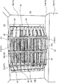
図1に示すように、本発明の第1実施形態は、試験室R1内に配置された供試体W1を所定の温度環境下に曝す試験を行う環境試験装置(チャンバー)10である。本実施形態に係る環境試験装置10は、供試体(ワーク)W1を所定の温度条件の雰囲気に曝して供試体W1に熱負荷を与える恒温槽として構成されている。なお、環境試験装置10は、これに限られるものではなく、供試体W1を所定の温度条件及び所定の湿度条件の雰囲気に曝して供試体W1に熱負荷を与える恒温恒湿槽として構成されていてもよい。この場合、加湿器がさらに設けられることになる。
図9に示すように、本発明の第2実施形態は、熱処理室(ワーク室)R3内に配置された被処理体(ワーク)W3を所定の温度環境に曝して、被処理体W3に熱処理を施すための熱処理装置(チャンバー)50である。尚、ここでは第1実施形態と同じ構成要素には同じ符号を付し、その詳細な説明を省略する。
16 仕切部材
21 中央部
26 送風機
26b 回転軸
26c 羽根車
33 整流部材
35 指詰め防止部材
35a 孔
38 羽根部
40 障害部
42 副障害部
50 熱処理装置
R1 試験室
R2 空調室
R3 熱処理室
W1 供試体
W3 被処理体
P1 第1仮想平面
P2 第2仮想平面
Claims (14)
- 試験室を形成する内壁面の中央部から所定方向にずれた位置に配置された回転軸を有する軸流ファンからなり、試験室内に空調空気を吹き出す送風機と、
前記送風機の吹き出し側において空調空気の気流の向きを調整する整流部材と、
前記送風機の吹き出し側において空調空気の流れを妨げる障害部と、を備え、
前記障害部は、前記回転軸を含み前記所定方向に沿う第1仮想平面に対して、前記送風機の作動時に前記軸流ファンの羽根が前記所定方向に向かって動く側において、前記回転軸を含み且つ前記第1仮想平面に垂直な第2仮想平面に対して前記所定方向にずれた位置に配置された部位を有する環境試験装置。 - 前記障害部は、前記第2仮想平面に対して前記所定方向にずれた位置から、前記第2仮想平面に対して前記所定方向とは反対方向にずれた位置まで亘る平板状に形成されている請求項1に記載の環境試験装置。
- 前記第1仮想平面に対して、前記送風機の作動時に前記軸流ファンの羽根が前記所定方向とは反対側に向かって動く側において、前記第2仮想平面に対して前記所定方向にずれた位置に配置された副障害部を備えている請求項1又は2に記載の環境試験装置。
- 多数の孔が形成された部材によって構成され、前記送風機に指が進入するのを防止する指詰め防止部材を備えている請求項1から3の何れか1項に記載の環境試験装置。
- 前記障害部は、前記指詰め防止部材に設けられている請求項4に記載の環境試験装置。
- 前記整流部材は、枠部と、互いに間隔をおいて配置され、向きが変えられるように両端が前記枠部に結合された多数の羽根部と、を有している請求項1から5の何れか1項に記載の環境試験装置。
- 前記送風機の作動によって試験室内の空気を流入させ、前記空気を調整して空調空気とする空調室を有し、
前記送風機の前記回転軸は、前記中央部から前記所定方向としての上方向にずれた位置に配置され、
前記送風機は、前記空調室内を下から上に向かって流れた空調空気を吸い込んで前記試験室内に吹き出す請求項1から6の何れか1項に記載の環境試験装置。 - 熱処理室を形成する内壁面の中央部から所定方向にずれた位置に配置された回転軸を有する軸流ファンからなり、熱処理室内に空調空気を吹き出す送風機と、
前記送風機の吹き出し側において空調空気の気流の向きを調整する整流部材と、
前記送風機の吹き出し側において空調空気の流れを妨げる障害部と、を備え、
前記障害部は、前記回転軸を含み前記所定方向に沿う第1仮想平面に対して、前記送風機の作動時に前記軸流ファンの羽根が前記所定方向に向かって動く側において、前記回転軸を含み且つ前記第1仮想平面に垂直な第2仮想平面に対して前記所定方向にずれた位置に配置された部位を有する熱処理装置。 - 前記障害部は、前記第2仮想平面に対して前記所定方向にずれた位置から、前記第2仮想平面に対して前記所定方向とは反対方向にずれた位置まで亘る平板状に形成されている請求項8に記載の熱処理装置。
- 前記第1仮想平面に対して、前記送風機の作動時に前記軸流ファンの羽根が前記所定方向とは反対側に向かって動く側において、前記第2仮想平面に対して前記所定方向にずれた位置に配置された副障害部を備えている請求項8又は9に記載の熱処理装置。
- 多数の孔が形成された部材によって構成され、前記送風機に指が進入するのを防止する指詰め防止部材を備えている請求項8から10の何れか1項に記載の熱処理装置。
- 前記障害部は、前記指詰め防止部材に設けられている請求項11に記載の熱処理装置。
- 前記整流部材は、枠部と、互いに間隔をおいて配置され、向きが変えられるように両端が前記枠部に結合された多数の羽根部と、を有している請求項8から12の何れか1項に記載の熱処理装置。
- 前記送風機の作動によって熱処理室内の空気を流入させ、前記空気を調整して空調空気とする空調室を有し、
前記送風機の前記回転軸は、前記中央部から前記所定方向としての上方向にずれた位置に配置され、
前記送風機は、前記空調室内を下から上に向かって流れた空調空気を吸い込んで前記熱処理室内に吹き出す請求項8から13の何れか1項に記載の熱処理装置。
Priority Applications (3)
| Application Number | Priority Date | Filing Date | Title |
|---|---|---|---|
| JP2017105459A JP6657141B2 (ja) | 2017-05-29 | 2017-05-29 | 環境試験装置及び熱処理装置 |
| DE102018106823.9A DE102018106823A1 (de) | 2017-05-29 | 2018-03-22 | Umgebungstestvorrichtung und Wärmebehandlungsvorrichtung |
| CN201810245002.5A CN108931472B (zh) | 2017-05-29 | 2018-03-23 | 环境试验装置以及热处理装置 |
Applications Claiming Priority (1)
| Application Number | Priority Date | Filing Date | Title |
|---|---|---|---|
| JP2017105459A JP6657141B2 (ja) | 2017-05-29 | 2017-05-29 | 環境試験装置及び熱処理装置 |
Publications (3)
| Publication Number | Publication Date |
|---|---|
| JP2018200254A JP2018200254A (ja) | 2018-12-20 |
| JP2018200254A5 JP2018200254A5 (ja) | 2019-04-25 |
| JP6657141B2 true JP6657141B2 (ja) | 2020-03-04 |
Family
ID=64109355
Family Applications (1)
| Application Number | Title | Priority Date | Filing Date |
|---|---|---|---|
| JP2017105459A Active JP6657141B2 (ja) | 2017-05-29 | 2017-05-29 | 環境試験装置及び熱処理装置 |
Country Status (3)
| Country | Link |
|---|---|
| JP (1) | JP6657141B2 (ja) |
| CN (1) | CN108931472B (ja) |
| DE (1) | DE102018106823A1 (ja) |
Families Citing this family (2)
| Publication number | Priority date | Publication date | Assignee | Title |
|---|---|---|---|---|
| CN113899555B (zh) * | 2021-12-10 | 2022-04-08 | 中国飞机强度研究所 | 一种实验室飞机发动机慢车运行环境场平衡控制系统 |
| CN113899554B (zh) * | 2021-12-10 | 2022-02-18 | 中国飞机强度研究所 | 实验室飞机发动机慢车运行环境场平衡控制方法 |
Family Cites Families (23)
| Publication number | Priority date | Publication date | Assignee | Title |
|---|---|---|---|---|
| JPS5918290Y2 (ja) * | 1982-10-25 | 1984-05-26 | 三洋電機株式会社 | 恒温庫 |
| JPS61155727A (ja) * | 1984-12-27 | 1986-07-15 | Suga Shikenki Kk | 複合腐食サイクル試験装置 |
| JPS61240071A (ja) * | 1985-04-17 | 1986-10-25 | 株式会社日立製作所 | 冷蔵庫 |
| JPS63108282A (ja) * | 1986-10-24 | 1988-05-13 | Yamato Scient Co Ltd | 恒温・恒湿試験装置 |
| DE3700976C1 (de) * | 1987-01-15 | 1988-07-21 | Heraeus Voetsch Gmbh | Klimapruefkammer |
| JP2535236Y2 (ja) * | 1989-10-24 | 1997-05-07 | 株式会社高見沢サイバネティックス | 恒温槽 |
| CN2146685Y (zh) * | 1992-08-21 | 1993-11-17 | 韩国斌 | 一种空气冷却器 |
| JP2534312Y2 (ja) * | 1992-09-07 | 1997-04-30 | タバイエスペック株式会社 | 目的とする温度及び(又は)湿度環境を得る装置 |
| JP3145634B2 (ja) * | 1996-04-11 | 2001-03-12 | タバイエスペック株式会社 | 温度分布調整式恒温装置 |
| US5783439A (en) * | 1997-04-30 | 1998-07-21 | Becton Dickinson And Company | Forced hot air heating device |
| JP2001017868A (ja) * | 1999-07-06 | 2001-01-23 | Nittetsu Elex Co Ltd | 試験用恒温装置 |
| TW438953B (en) * | 1999-09-20 | 2001-06-07 | Mitsubishi Electric Corp | Blower, blower system and the blowing method of blower system |
| JP3961396B2 (ja) * | 2002-10-29 | 2007-08-22 | エスペック株式会社 | 密閉型試験器 |
| CN201537495U (zh) * | 2009-07-31 | 2010-08-04 | 赵庆峰 | 安全级别的净化药物配制设备的空气净化系统 |
| KR200450874Y1 (ko) * | 2010-04-15 | 2010-11-08 | 오성에스티주식회사 | 열충격 시험장치 |
| JP5699108B2 (ja) * | 2012-04-27 | 2015-04-08 | エスペック株式会社 | 環境試験装置 |
| CN202870009U (zh) * | 2012-11-12 | 2013-04-10 | 广东宏展科技有限公司 | 温度快速变化的试验箱 |
| JP6139171B2 (ja) * | 2013-02-20 | 2017-05-31 | シャープ株式会社 | 送風機 |
| WO2015001663A1 (ja) * | 2013-07-05 | 2015-01-08 | 三菱電機株式会社 | 送風機及び室外機 |
| CN203375559U (zh) * | 2013-07-10 | 2014-01-01 | 邝嘉豪 | 一种热泵型窗式空调器 |
| DE102014118787A1 (de) * | 2014-12-16 | 2016-06-16 | Binder Gmbh | Simulationsschrank |
| CN204855291U (zh) * | 2015-07-28 | 2015-12-09 | 上海启津测试技术有限公司 | 一种冷热冲击箱 |
| JP6291098B2 (ja) | 2017-02-20 | 2018-03-14 | スリーエム イノベイティブ プロパティズ カンパニー | 自動ライセンスプレート読み取りシステムの読み取り精度を高めるための方法及びシステム |
-
2017
- 2017-05-29 JP JP2017105459A patent/JP6657141B2/ja active Active
-
2018
- 2018-03-22 DE DE102018106823.9A patent/DE102018106823A1/de active Pending
- 2018-03-23 CN CN201810245002.5A patent/CN108931472B/zh active Active
Also Published As
| Publication number | Publication date |
|---|---|
| CN108931472B (zh) | 2021-06-08 |
| JP2018200254A (ja) | 2018-12-20 |
| CN108931472A (zh) | 2018-12-04 |
| DE102018106823A1 (de) | 2018-11-29 |
Similar Documents
| Publication | Publication Date | Title |
|---|---|---|
| JP6129126B2 (ja) | 空気調和機の室内機 | |
| JP4859777B2 (ja) | 室外ユニット | |
| WO2010119893A1 (ja) | 空気調和装置 | |
| JP6657141B2 (ja) | 環境試験装置及び熱処理装置 | |
| JP2010060242A (ja) | 空気調和装置の室外ユニット | |
| JP2019178835A (ja) | 天井埋込型空気調和機 | |
| JP4519811B2 (ja) | 空気調和装置 | |
| JP2008267727A (ja) | 冷凍空調装置 | |
| JP6111947B2 (ja) | 空気調和機 | |
| JP2005024225A (ja) | 空気調和機 | |
| JP2017172935A (ja) | 空気調和機 | |
| JP6799750B2 (ja) | 熱交換機器 | |
| JP6233120B2 (ja) | ダクト型空気調和機 | |
| JP6861333B2 (ja) | エアカーテン | |
| EP3798524A1 (en) | Air blowing device and air conditioner | |
| JPH1082550A (ja) | 空気調和機 | |
| JP4612067B2 (ja) | 空調吹出装置 | |
| JP2018091563A (ja) | 空気調和機の室内機 | |
| JP4905033B2 (ja) | ファンフィルターユニット | |
| JP6896140B2 (ja) | 空気調和機の室外機 | |
| JPWO2018029798A1 (ja) | 空気調和装置の室外機 | |
| JP7246942B2 (ja) | 環境形成装置 | |
| JP2013181715A (ja) | 空調システムおよび空調方法 | |
| JP6923845B2 (ja) | ダクト型空気調和機 | |
| JP7472364B2 (ja) | パーソナル空調システム |
Legal Events
| Date | Code | Title | Description |
|---|---|---|---|
| A521 | Request for written amendment filed |
Free format text: JAPANESE INTERMEDIATE CODE: A523 Effective date: 20190315 |
|
| A621 | Written request for application examination |
Free format text: JAPANESE INTERMEDIATE CODE: A621 Effective date: 20190315 |
|
| A977 | Report on retrieval |
Free format text: JAPANESE INTERMEDIATE CODE: A971007 Effective date: 20200121 |
|
| TRDD | Decision of grant or rejection written | ||
| A01 | Written decision to grant a patent or to grant a registration (utility model) |
Free format text: JAPANESE INTERMEDIATE CODE: A01 Effective date: 20200128 |
|
| A61 | First payment of annual fees (during grant procedure) |
Free format text: JAPANESE INTERMEDIATE CODE: A61 Effective date: 20200205 |
|
| R150 | Certificate of patent or registration of utility model |
Ref document number: 6657141 Country of ref document: JP Free format text: JAPANESE INTERMEDIATE CODE: R150 |
|
| R250 | Receipt of annual fees |
Free format text: JAPANESE INTERMEDIATE CODE: R250 |
|
| R250 | Receipt of annual fees |
Free format text: JAPANESE INTERMEDIATE CODE: R250 |