JP6657141B2 - Environmental test equipment and heat treatment equipment - Google Patents
Environmental test equipment and heat treatment equipment Download PDFInfo
- Publication number
- JP6657141B2 JP6657141B2 JP2017105459A JP2017105459A JP6657141B2 JP 6657141 B2 JP6657141 B2 JP 6657141B2 JP 2017105459 A JP2017105459 A JP 2017105459A JP 2017105459 A JP2017105459 A JP 2017105459A JP 6657141 B2 JP6657141 B2 JP 6657141B2
- Authority
- JP
- Japan
- Prior art keywords
- blower
- virtual plane
- air
- predetermined direction
- obstacle
- Prior art date
- Legal status (The legal status is an assumption and is not a legal conclusion. Google has not performed a legal analysis and makes no representation as to the accuracy of the status listed.)
- Active
Links
- 238000012360 testing method Methods 0.000 title claims description 122
- 238000010438 heat treatment Methods 0.000 title claims description 51
- 230000007613 environmental effect Effects 0.000 title claims description 35
- 230000001143 conditioned effect Effects 0.000 claims description 71
- 230000002265 prevention Effects 0.000 claims description 51
- 238000004378 air conditioning Methods 0.000 claims description 37
- 238000007664 blowing Methods 0.000 claims description 6
- 238000005192 partition Methods 0.000 description 75
- 238000004891 communication Methods 0.000 description 15
- 230000001105 regulatory effect Effects 0.000 description 10
- 230000008878 coupling Effects 0.000 description 7
- 238000010168 coupling process Methods 0.000 description 7
- 238000005859 coupling reaction Methods 0.000 description 7
- 230000008859 change Effects 0.000 description 5
- 239000002184 metal Substances 0.000 description 5
- 230000007480 spreading Effects 0.000 description 4
- 238000003780 insertion Methods 0.000 description 3
- 230000037431 insertion Effects 0.000 description 3
- 238000009434 installation Methods 0.000 description 3
- 238000012986 modification Methods 0.000 description 2
- 230000004048 modification Effects 0.000 description 2
- 238000005452 bending Methods 0.000 description 1
- 230000015572 biosynthetic process Effects 0.000 description 1
- 238000001816 cooling Methods 0.000 description 1
- 238000006073 displacement reaction Methods 0.000 description 1
- 230000000694 effects Effects 0.000 description 1
- 238000005516 engineering process Methods 0.000 description 1
- 239000011810 insulating material Substances 0.000 description 1
- 238000011835 investigation Methods 0.000 description 1
- 238000012545 processing Methods 0.000 description 1
- 238000004080 punching Methods 0.000 description 1
- 239000011347 resin Substances 0.000 description 1
- 229920005989 resin Polymers 0.000 description 1
Images


Classifications
-
- G—PHYSICS
- G01—MEASURING; TESTING
- G01N—INVESTIGATING OR ANALYSING MATERIALS BY DETERMINING THEIR CHEMICAL OR PHYSICAL PROPERTIES
- G01N17/00—Investigating resistance of materials to the weather, to corrosion, or to light
-
- G—PHYSICS
- G01—MEASURING; TESTING
- G01N—INVESTIGATING OR ANALYSING MATERIALS BY DETERMINING THEIR CHEMICAL OR PHYSICAL PROPERTIES
- G01N17/00—Investigating resistance of materials to the weather, to corrosion, or to light
- G01N17/002—Test chambers
-
- G—PHYSICS
- G01—MEASURING; TESTING
- G01N—INVESTIGATING OR ANALYSING MATERIALS BY DETERMINING THEIR CHEMICAL OR PHYSICAL PROPERTIES
- G01N3/00—Investigating strength properties of solid materials by application of mechanical stress
- G01N3/60—Investigating resistance of materials, e.g. refractory materials, to rapid heat changes
Description
本発明は、環境試験装置及び熱処理装置に関するものである。 The present invention relates to an environmental test device and a heat treatment device.
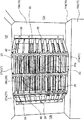
従来、試験室内を所定の温度・湿度に調整し、試験室内に配置された供試体を当該試験環境下に曝させて供試体の性能等を試験する環境試験装置が知られている。例えば特許文献1に開示された環境試験装置は、図10に示すように、供試体が配置される試験室81と、試験室81内の温度を調整するための空調室82とを備える。冷却器83及び有孔板84は試験室81と空調室82とを仕切る仕切壁を構成している。加熱器85及び送風機86は空調室82に配置されている。送風機86は、試験室81の側壁(有孔板84)の略中央に位置するように配置されている。
2. Description of the Related Art Conventionally, there has been known an environmental test apparatus in which a test chamber is adjusted to a predetermined temperature and humidity, and a test specimen placed in the test chamber is exposed to the test environment to test the performance and the like of the test specimen. For example, as shown in FIG. 10, the environmental test apparatus disclosed in Patent Document 1 includes a
特許文献1に開示された環境試験装置では、送風機86が試験室81の側壁(有孔板84)の略中央に位置されているが、送風機86は側壁の略中央に配置されるとは限らない。例えば、送風機86は、側壁の中央位置からずれた位置に配置されることもある。その場合の試験室81の温度分布を調査してみると、試験室81内の温度に分布が生じ易いことが判明した。この点は、環境試験装置に限られず、熱処理室内において被処理体に熱処理を施す熱処理装置においても同様である。
In the environmental test apparatus disclosed in Patent Document 1, the
そこで、本発明は、前記従来技術を鑑みてなされたものであり、その目的とするところは、送風機が試験室又は熱処理室の内壁面の中央部からずれた位置に配置される環境試験装置又は熱処理装置において、試験室内又は熱処理室内の温度分布が生ずることを抑制できるようにすることにある。 Therefore, the present invention has been made in view of the above-described conventional technology, and an object thereof is to provide an environmental test apparatus in which a blower is disposed at a position displaced from a central portion of an inner wall surface of a test room or a heat treatment room. In a heat treatment apparatus, it is possible to suppress occurrence of a temperature distribution in a test room or a heat treatment room.
本発明者等は、例えば、送風機が内壁面の中央部よりも上側にずれた位置に配置されている場合の温度分布を調査した。その場合には、試験室内の上側で相対的に温度の変化が早く、下側で相対的に温度変化が遅くなることから、加熱空気を生成する場合には、試験室内の上側で相対的に温度が高く、下側で温度が相対的に低くなる傾向があることが判明した。しかも、試験室の上側の中でも、送風機の回転方向との関係で、温度分布が生じていることも判明した。そこで、前記の目的を達成するため、本発明者らは、鋭意検討を重ねた結果、温度分布が、送風機の配置位置の内壁面の中央部からのずれ方向及び送風機の羽根の回転方向に関係していることを見出し、本発明を創案することができた。 The present inventors investigated, for example, the temperature distribution in the case where the blower was arranged at a position shifted upward from the center of the inner wall surface. In that case, the change in temperature is relatively fast in the upper part of the test chamber, and the change in temperature is relatively slow in the lower part. It has been found that the temperature is high and the temperature tends to be relatively low on the lower side. Moreover, it was also found that a temperature distribution occurred in the upper part of the test chamber in relation to the rotation direction of the blower. Therefore, in order to achieve the above object, the present inventors have conducted intensive studies and found that the temperature distribution is related to the direction of displacement of the arrangement position of the blower from the center of the inner wall surface and the rotation direction of the blades of the blower. And found that the present invention was invented.
本発明に係る環境試験装置は、試験室を形成する内壁面の中央部から所定方向にずれた位置に配置された回転軸を有する軸流ファンからなり、試験室内に空調空気を吹き出す送風機と、前記送風機の吹き出し側において空調空気の気流の向きを調整する整流部材と、前記送風機の吹き出し側において空調空気の流れを妨げる障害部と、を備える。前記障害部は、前記回転軸を含み前記所定方向に沿う第1仮想平面に対して、前記送風機の作動時に前記軸流ファンの羽根が前記所定方向に向かって動く側において、前記回転軸を含み且つ前記第1仮想平面に垂直な第2仮想平面に対して前記所定方向にずれた位置に配置された部位を有する。 The environmental test apparatus according to the present invention includes an axial fan having a rotating shaft arranged in a position shifted in a predetermined direction from a central portion of an inner wall forming a test chamber, and a blower that blows conditioned air into the test chamber, The air conditioner includes a rectifying member that adjusts the direction of the airflow of the conditioned air on the blowout side of the blower, and an obstacle that blocks the flow of the conditioned air on the blowout side of the blower. The obstacle includes the rotation axis on a side where the blade of the axial fan moves toward the predetermined direction when the blower is operated with respect to a first virtual plane including the rotation axis and along the predetermined direction. And a portion arranged at a position shifted in the predetermined direction with respect to a second virtual plane perpendicular to the first virtual plane.
本発明では、軸流ファンからなる送風機の吹き出し側において、整流部材が、空調空気の気流の向きを調整する。一方、送風機の吹き出し側には、空調空気の流れを妨げる障害部も設けられている。この障害部は、整流部材による気流の向きの調整のみによっては解消できない試験室内の温度のばらつきを抑制すべく、送風機の吹き出し側において特定の領域に配置された部位を有する。すなわち、障害部は、送風機の回転軸を含み前記所定方向に沿う第1仮想平面に対して、送風機の作動時に羽根が前記所定方向に向かって動く側において、第1仮想平面に垂直な第2仮想平面に対して前記所定方向にずれた位置である特定領域に配置された部位を有する。障害部によって空調空気の流れが妨げられることにより、試験室内の温度のばらつきが抑制される。より具体的には、送風機の回転軸が、試験室を形成する内壁面の中央部から所定方向にずれているため、障害部がなければ、送風機から吹き出された空調空気は、この所定方向にずれた方向に位置する試験室の内面に沿って流れ易くなる。そして、試験室内では、回転軸を含み前記所定方向に沿う第1仮想平面に対して、軸流ファンの羽根が前記所定方向に向かって動く側においては、回転軸を含み且つ前記第1仮想平面に垂直な第2仮想平面よりも前記所定方向側に位置する特定領域において、空調空気の風量がより多くなる。したがって、前記特定の位置に配置された部位を有する障害部が設けられることにより、前記特定領域で空調空気の風量が多くなることが抑制され、その結果、試験室内の温度のばらつきを抑制することができる。 In the present invention, the rectifying member adjusts the direction of the airflow of the conditioned air on the blowout side of the blower including the axial fan. On the other hand, an obstruction that hinders the flow of the conditioned air is also provided on the blowout side of the blower. The obstruction has a portion arranged in a specific area on the blow-off side of the blower in order to suppress a variation in temperature in the test chamber that cannot be eliminated only by adjusting the direction of the airflow by the rectifying member. That is, the obstruction portion is a second virtual plane perpendicular to the first virtual plane on the side where the blade moves in the predetermined direction when the blower is operated with respect to the first virtual plane including the rotation axis of the blower and along the predetermined direction. It has a part arranged in a specific area which is a position shifted in the predetermined direction with respect to the virtual plane. Since the flow of the conditioned air is obstructed by the obstacle, the temperature variation in the test room is suppressed. More specifically, since the rotation axis of the blower is displaced in a predetermined direction from the center of the inner wall forming the test chamber, if there is no obstruction, the conditioned air blown out of the blower in this predetermined direction It is easier to flow along the inner surface of the test chamber located in the shifted direction. Then, in the test chamber, on the side where the blade of the axial fan moves in the predetermined direction with respect to the first virtual plane including the rotation axis and along the predetermined direction, the first virtual plane includes the rotation axis and includes the rotation axis. The air volume of the conditioned air is larger in the specific area located on the predetermined direction side than the second virtual plane perpendicular to the second virtual plane. Therefore, the provision of the obstacle having the portion arranged at the specific position suppresses an increase in the air volume of the conditioned air in the specific region, and as a result, suppresses the temperature variation in the test chamber. Can be.
前記障害部は、前記第2仮想平面に対して前記所定方向にずれた位置から、前記第2仮想平面に対して前記所定方向とは反対方向にずれた位置まで亘る平板状に形成されていてもよい。 The obstacle is formed in a flat plate shape from a position shifted in the predetermined direction with respect to the second virtual plane to a position shifted in a direction opposite to the predetermined direction with respect to the second virtual plane. Is also good.
第2仮想平面に対して前記所定方向にずれた位置にだけ障害部が配置されても、試験室内の温度のばらつきを抑制することができる。一方、障害部が、第2仮想平面に対して前記所定方向にずれた位置から、前記第2仮想平面に対して前記所定方向とは反対方向にずれた位置まで亘る範囲に設けられる場合、前記特定領域での風量をより効果的に抑制することができる。また、障害物が平板状に形成されることにより、障害部を簡素な部材で実現することができる。 Even if the obstacle is disposed only at a position shifted in the predetermined direction with respect to the second virtual plane, it is possible to suppress the variation in the temperature in the test chamber. On the other hand, when the obstacle is provided in a range from a position shifted in the predetermined direction with respect to a second virtual plane to a position shifted in a direction opposite to the predetermined direction with respect to the second virtual plane, The air volume in the specific area can be more effectively suppressed. Further, since the obstacle is formed in a flat plate shape, the obstacle can be realized by a simple member.
前記環境試験装置は、前記第1仮想平面に対して、前記送風機の作動時に前記軸流ファンの羽根が前記所定方向とは反対側に向かって動く側において、前記第2仮想平面に対して前記所定方向にずれた位置に配置された副障害部を備えていてもよい。 The environmental test apparatus is configured such that, with respect to the first virtual plane, the blade of the axial fan moves toward the side opposite to the predetermined direction when the blower is operated, and A sub-obstacle may be provided at a position shifted in a predetermined direction.
この態様では、前記特定領域で空調空気の風量が多くなることを抑制するだけでなく、前記第1仮想平面に対して前記特定領域とは反対側の領域で空調空気の風量が多くなることも抑制することができる。この結果、試験室内の温度のばらつきをより抑制することができる。 In this aspect, not only does the air volume of the conditioned air increase in the specific area, but also the air volume of the conditioned air increases in the area opposite to the specific area with respect to the first virtual plane. Can be suppressed. As a result, the variation in the temperature in the test chamber can be further suppressed.
前記環境試験装置は、多数の孔が形成された部材によって構成され、前記送風機に指が進入するのを防止する指詰め防止部材を備えていてもよい。 The environmental test apparatus may be configured by a member having a large number of holes formed therein, and may include a finger jam prevention member that prevents a finger from entering the blower.
この態様では、送風機からの空調空気の通過を許容しつつ、試験室内での安全を確保することができる。 In this aspect, safety in the test room can be ensured while allowing the passage of the conditioned air from the blower.
前記障害部は、前記指詰め防止部材に設けられていてもよい。この態様では、部品点数が増大することを抑制することができる。 The obstacle may be provided on the finger jam prevention member. In this aspect, an increase in the number of parts can be suppressed.
前記整流部材は、枠部と、互いに間隔をおいて配置され、向きが変えられるように両端が前記枠部に結合された多数の羽根部と、を有していてもよい。 The rectifying member may include a frame portion and a plurality of blade portions that are arranged at an interval from each other and that are coupled to the frame portion at both ends so that the directions can be changed.
この態様では、羽根部の向きを変えることによって気流の向きを調整することができる。したがって、整流部材の設置環境に応じて各羽根部の向きをそれぞれ調整することにより、試験室内の温度分布の微調整を行うことができる。 In this embodiment, the direction of the airflow can be adjusted by changing the direction of the blade. Therefore, fine adjustment of the temperature distribution in the test chamber can be performed by adjusting the direction of each blade in accordance with the installation environment of the rectifying member.
前記環境試験装置は、前記送風機の作動によって試験室内の空気を流入させ、前記空気を調整して空調空気とする空調室を有してもよい。この場合、前記送風機の前記回転軸は、前記中央部から前記所定方向としての上方向にずれた位置に配置されてもよい。また、前記送風機は、前記空調室内を下から上に向かって流れた空調空気を吸い込んで前記試験室内に吹き出してもよい。 The environmental test apparatus may include an air conditioning room that causes air in a test room to flow in by operating the blower, adjusts the air, and turns the air into conditioned air. In this case, the rotation axis of the blower may be arranged at a position shifted upward from the central portion as the predetermined direction. Further, the blower may suck air-conditioned air flowing upward from below in the air-conditioned room and blow it out into the test room.
この態様では、送風機は、空調室内を下から上に向かって流れた空調空気を吸い込んで試験室内に吹き出す。このため、障害部がなければ、空調室からの空調空気の吹き出し方向が空調室内での空調空気の流れ方向の影響を受ける可能性がある。しかしながら、障害部を有効に機能させることによって、試験室内での温度のばらつきを抑止することができる。すなわち、送風機は、空調室内を下から上に流れた空調空気を吸い込んで試験室内に吹き出すため、障害部が無ければ、空調空気は斜め上に向けて吹き出される傾向がある。しかしながら、障害部の存在によって、空調空気が斜め上に向けて吹き出すことを抑制することができる。これにより、試験室内での温度のばらつきを抑止することができる。 In this aspect, the blower sucks the conditioned air flowing from the bottom to the top in the air-conditioned room and blows out the air into the test room. For this reason, if there is no obstacle, the blowing direction of the conditioned air from the air-conditioned room may be affected by the flow direction of the conditioned air in the air-conditioned room. However, by making the obstacle function effectively, it is possible to suppress temperature variations in the test room. That is, since the blower sucks in the conditioned air flowing from the bottom to the top in the air-conditioned room and blows it out into the test room, the conditioned air tends to be blown obliquely upward unless there is an obstacle. However, due to the presence of the obstacle, the conditioned air can be prevented from blowing obliquely upward. As a result, it is possible to suppress temperature variations in the test chamber.
本発明に係る熱処理装置は、熱処理室を形成する内壁面の中央部から所定方向にずれた位置に配置された回転軸を有する軸流ファンからなり、熱処理室内に空調空気を吹き出す送風機と、前記送風機の吹き出し側において空調空気の気流の向きを調整する整流部材と、前記送風機の吹き出し側において空調空気の流れを妨げる障害部と、を備える。前記障害部は、前記回転軸を含み前記所定方向に沿う第1仮想平面に対して、前記送風機の作動時に前記軸流ファンの羽根が前記所定方向に向かって動く側において、前記回転軸を含み且つ前記第1仮想平面に垂直な第2仮想平面に対して前記所定方向にずれた位置に配置された部位を有する。 The heat treatment apparatus according to the present invention comprises an axial fan having a rotating shaft disposed at a position shifted in a predetermined direction from a central portion of an inner wall surface forming the heat treatment chamber, and a blower that blows out conditioned air into the heat treatment chamber; The air conditioner includes a rectifying member that adjusts the direction of the airflow of the conditioned air on the blowout side of the blower, and an obstacle that blocks the flow of the conditioned air on the blowout side of the blower. The obstacle includes the rotation axis on a side where the blade of the axial fan moves toward the predetermined direction when the blower is operated with respect to a first virtual plane including the rotation axis and along the predetermined direction. And a portion arranged at a position shifted in the predetermined direction with respect to a second virtual plane perpendicular to the first virtual plane.
本発明では、軸流ファンからなる送風機の吹き出し側において、整流部材が、空調空気の気流の向きを調整する。一方、送風機の吹き出し側には、空調空気の流れを妨げる障害部も設けられている。この障害部は、整流部材による気流の向きの調整のみによっては解消できない熱処理室内の温度のばらつきを抑制すべく、送風機の吹き出し側において特定の領域に配置された部位を有する。すなわち、障害部は、送風機の回転軸を含み前記所定方向に沿う第1仮想平面に対して、送風機の作動時に羽根が前記所定方向に向かって動く側において、第1仮想平面に垂直な第2仮想平面に対して前記所定方向にずれた位置である特定領域に配置された部位を有する。障害部によって空調空気の流れが妨げられることにより、熱処理室内の温度のばらつきが抑制される。より具体的には、送風機の回転軸が、熱処理室を形成する内壁面の中央部から所定方向にずれているため、障害部がなければ、送風機から吹き出された空調空気は、この所定方向にずれた方向に位置する試験室の内面に沿って流れ易くなる。そして、熱処理室内では、回転軸を含み前記所定方向に沿う第1仮想平面に対して、軸流ファンの羽根が前記所定方向に向かって動く側においては、回転軸を含み且つ前記第1仮想平面に垂直な第2仮想平面よりも前記所定方向側に位置する特定領域において、空調空気の風量がより多くなる。したがって、前記特定の位置に配置された部位を有する障害部が設けられることにより、前記特定領域で空調空気の風量が多くなることを抑制することができ、その結果、熱処理室内の温度のばらつきを抑制することができる。 In the present invention, the rectifying member adjusts the direction of the airflow of the conditioned air on the blowout side of the blower including the axial fan. On the other hand, an obstruction that hinders the flow of the conditioned air is also provided on the blowout side of the blower. The obstruction has a portion arranged in a specific region on the blow-off side of the blower in order to suppress a temperature variation in the heat treatment chamber that cannot be eliminated only by adjusting the direction of the airflow by the rectifying member. That is, the obstruction portion is a second virtual plane perpendicular to the first virtual plane on the side where the blade moves in the predetermined direction when the blower is operated with respect to the first virtual plane including the rotation axis of the blower and along the predetermined direction. It has a part arranged in a specific area which is a position shifted in the predetermined direction with respect to the virtual plane. Since the flow of the conditioned air is obstructed by the obstacle, the temperature variation in the heat treatment chamber is suppressed. More specifically, since the rotation axis of the blower is displaced in a predetermined direction from the central portion of the inner wall surface forming the heat treatment chamber, if there is no obstacle, the conditioned air blown out from the blower in this predetermined direction. It is easier to flow along the inner surface of the test chamber located in the shifted direction. Then, in the heat treatment chamber, on the side where the blade of the axial fan moves in the predetermined direction with respect to the first virtual plane including the rotation axis and along the predetermined direction, the first virtual plane includes the rotation axis and includes the rotation axis. The air volume of the conditioned air is larger in the specific area located on the predetermined direction side than the second virtual plane perpendicular to the second virtual plane. Therefore, by providing the obstacle having the portion arranged at the specific position, it is possible to suppress an increase in the air volume of the conditioned air in the specific region, and as a result, the temperature variation in the heat treatment chamber is reduced. Can be suppressed.
前記障害部は、前記第2仮想平面に対して前記所定方向にずれた位置から、前記第2仮想平面に対して前記所定方向とは反対方向にずれた位置まで亘る平板状に形成されていてもよい。 The obstacle is formed in a flat plate shape from a position shifted in the predetermined direction with respect to the second virtual plane to a position shifted in a direction opposite to the predetermined direction with respect to the second virtual plane. Is also good.
前記熱処理装置は、前記第1仮想平面に対して、前記送風機の作動時に前記軸流ファンの羽根が前記所定方向とは反対側に向かって動く側において、前記第2仮想平面に対して前記所定方向にずれた位置に配置された副障害部を備えていてもよい。 The heat treatment apparatus is configured such that, when the blower is operated, the blade of the axial fan moves toward the opposite side to the predetermined direction with respect to the first virtual plane. A sub-obstacle may be provided at a position shifted in the direction.
前記熱処理装置は、多数の孔が形成された部材によって構成され、前記送風機に指が進入するのを防止する指詰め防止部材を備えていてもよい。 The heat treatment apparatus may include a member in which a number of holes are formed, and may include a finger jamming prevention member that prevents a finger from entering the blower.
前記障害部は、前記指詰め防止部材に設けられていてもよい。 The obstacle may be provided on the finger jam prevention member.
前記整流部材は、枠部と、互いに間隔をおいて配置され、向きが変えられるように両端が前記枠部に結合された多数の羽根部と、を有していてもよい。 The rectifying member may include a frame portion and a plurality of blade portions that are arranged at an interval from each other and that are coupled to the frame portion at both ends so that the directions can be changed.
前記熱処理装置は、前記送風機の作動によって熱処理室内の空気を流入させ、前記空気を調整して空調空気とする空調室を有してもよい。この場合、前記送風機の前記回転軸は、前記中央部から前記所定方向としての上方向にずれた位置に配置されてもよい。また、前記送風機は、前記空調室内を下から上に向かって流れた空調空気を吸い込んで前記熱処理室内に吹き出してもよい。 The heat treatment apparatus may include an air conditioning room that causes air in the heat treatment chamber to flow in by operating the blower, adjusts the air, and turns the air into conditioned air. In this case, the rotation axis of the blower may be arranged at a position shifted upward from the central portion as the predetermined direction. Further, the blower may suck air-conditioned air flowing upward from below in the air-conditioned room and blow it out into the heat-treated room.
以上説明したように、本発明によれば、送風機が試験室又は熱処理室の内壁面の中央部からずれた位置に配置される環境試験装置又は熱処理装置において、試験室内又は熱処理室内の温度分布が生ずることを抑制することができる。 As described above, according to the present invention, in an environmental test apparatus or a heat treatment apparatus in which a blower is arranged at a position shifted from a central portion of an inner wall surface of a test room or a heat treatment room, the temperature distribution in the test room or the heat treatment room is This can be suppressed.
以下、本発明を実施するための形態について図面を参照しながら詳細に説明する。 Hereinafter, embodiments for carrying out the present invention will be described in detail with reference to the drawings.
(第1実施形態)
図1に示すように、本発明の第1実施形態は、試験室R1内に配置された供試体W1を所定の温度環境下に曝す試験を行う環境試験装置(チャンバー)10である。本実施形態に係る環境試験装置10は、供試体(ワーク)W1を所定の温度条件の雰囲気に曝して供試体W1に熱負荷を与える恒温槽として構成されている。なお、環境試験装置10は、これに限られるものではなく、供試体W1を所定の温度条件及び所定の湿度条件の雰囲気に曝して供試体W1に熱負荷を与える恒温恒湿槽として構成されていてもよい。この場合、加湿器がさらに設けられることになる。
(1st Embodiment)
As shown in FIG. 1, the first embodiment of the present invention is an environmental test apparatus (chamber) 10 for performing a test for exposing a specimen W1 placed in a test chamber R1 to a predetermined temperature environment. The
第1実施形態に係る環境試験装置10は、全体として直方体形状に形成された中空状のケーシング12を備えている。ケーシング12は、前側壁を構成する扉体12a、左側壁12b、右側壁12c(図2参照)、後側壁12d、底面部12e及び天部12fを備えている。ケーシング12は、金属製又は樹脂製のパネルで断熱材をカバーした断熱パネルによって構成されている。ケーシング12の後側には、機械室を区画する機械室ケーシング14が設けられている。なお、右側、左側は、扉体12a側を前側として、前側から見たときの右側、左側を意味している。
The
ケーシング12内には、仕切部材16が設けられており、この仕切部材16によって、ケーシング12内の空間は、2つの空間に区画されている。本実施形態では、仕切部材16は、ケーシング12内の前後方向の中間部に配置され、その前側に位置する空間と後側に位置する空間とに仕切っている。仕切部材16の前側の空間には、供試体W1が収容される。すなわち、左側壁12b、右側壁12c、底面部12e及び天部12fのそれぞれにおける仕切部材16よりも前側の部位と、扉体12aと、仕切部材16と、により、供試体W1が収容される試験室(ワーク室)R1が形成されている。したがって、仕切部材16の前面は、試験室R1を形成する1つの内壁面として機能する。同様に、左側壁12bの右面、右側壁12cの左面、扉体12aの後面、底面部12eの上面及び天部12fの下面は、それぞれ試験室R1を形成する内壁面として機能する。
A
一方、仕切部材16の後側の空間には、試験室R1内の温度環境を調整するための機器が収納される。すなわち、左側壁12b、右側壁12c、底面部12e及び天部12fにおける仕切部材16よりも後の部位と、後側壁12dと、仕切部材16と、により、試験室R1内の温度を調整するための機器が収容される空調室R2が形成されている。したがって、本実施形態では、試験室R1の後側に空調室R2が配置されている。仕切部材16の後面は、空調室R2を形成する1つの内壁面として機能する。同様に、左側壁12bの右面、右側壁12cの左面、後側壁12dの前面、底面部12eの上面及び天部12fの下面は、それぞれ空調室R2を形成する内壁面として機能する。
On the other hand, in the space on the rear side of the
試験室R1には、供試体W1を配置するための支持台18と、支持台18の設置位置を変えるための変更部材19とが設けられている。本実施形態では、変更部材19は、左側壁12b及び右側壁12cに設けられて、支持台18の高さを変更可能に構成されている。
The test room R1 is provided with a
仕切部材16は、中間部分に段差部16aが形成されている。すなわち、仕切部材16は、平面状の壁面を有する第1面部16bと、第1面部16bからずれた位置に配置された平面状の壁面を有する第2面部16cと、第1面部16b及び第2面部16cを結合する段差部16aと、を有する。本実施形態では、第1面部16b及び第2面部16cは、垂直姿勢で配置され、段差部16aは、水平姿勢で配置されている。第1面部16bは、第2面部16cよりも空調室R2側にずれた位置で第2面部16cよりも上側に位置している。仕切部材16は、例えば板金によって構成されている。本実施形態では、段差部16aは、仕切部材16の高さ方向の中央部21よりも上側に位置している。
The
仕切部材16には、空調室R2内の空間と試験室R1内の空間とを連通する2つの連通孔23,24が形成されている。第1連通孔23は、仕切部材16の高さ方向の中央部21よりも上に配置され、第2連通孔24は、仕切部材16の中央部21よりも下に配置されている。また、第1連通孔23は第1面部16bに形成され、第2連通孔24は、第2面部16cに形成されている。なお、第2連通孔24は、仕切部材16と底面部12eとの間の間隙によって形成されていてもよい。また、第1連通孔23は、仕切部材16と天部12fとの間の間隙によって形成されていてもよい。
The
本実施形態では、後述するように、送風機26から吹きされた空調空気が第1連通孔23を通して空調室R2内から試験室R1内に流入するため、第1連通孔23は、空調空気を吹き出す吹出口として機能する。一方、第2連通孔24においては、試験室R1内の空気が空調室R2内に流入するため、空気を吸い込む吸入口として機能する。
In the present embodiment, as will be described later, the conditioned air blown from the
空調室R2内には、空調室R2内の空気を冷却する冷却器28と、空調室R2内の空気を加熱する加熱器30と、送風機26と、が設けられている。空調室R2内の空気は、冷却器28及び加熱器30によって温度が調整されることにより、空調空気となる。
In the air conditioning room R2, a cooler 28 for cooling the air in the air conditioning room R2, a
送風機26は、後側壁12dに固定されたモータ26aと、モータ26aの回転軸26bに固定された羽根車26cとを有する軸流ファンによって構成されている。モータ26aは、後側壁12dの後側に配置された機械室内に位置している。回転軸26bは、後側壁12dを貫通し、空調室R2内を前方(試験室R1)に向かって延びている。回転軸26bの先端部は、仕切部材16の第1連通孔23の中心と同心位置に配置されている。羽根車26cは、回転軸26b周りに周方向に並ぶ複数の羽根を有している。そして、モータ26aが作動し、羽根車26cが回転すると、送風機26から吹き出された空調空気は第1連通孔23を通過して、試験室R1内に流入する。なお、送風機26は、モータ26aも空調室R2内に位置するように配置されていてもよい。
The
図2にも示すように、送風機26の吹き出し側には、整流部材33と指詰め防止部材35とが配置されている。整流部材33は、送風機26から吹き出された空調空気の気流の向きを調整するための部材である。指詰め防止部材35は、送風機26に指が進入するのを防止するための部材である。
As shown in FIG. 2, a rectifying
整流部材33は、図3に示すように、枠部37と、枠部37に支持された多数の羽根部38と、を有している。枠部37は、互いに間隔をおいて配置された複数の支持部材37aと、これら支持部材37aを結合する複数の結合部材37bと、を有する。本実施形態では、支持部材37aは上下に延びる姿勢を有し、結合部材37bは支持部材37aの上端及び下端に結合され、水平に延びる姿勢を有する。
As shown in FIG. 3, the
複数の羽根部38は、互いに間隔をおいて配置されている。各羽根部38の長手方向の一端は、互いに隣接する支持部材37aのうちの一方に結合され、各羽根部38の長手方向の他端は、互いに隣接する支持部材37aのうちの他方に結合されている。羽根部38は上下方向に間隔を空けて並ぶとともに、この羽根部38の列が水平方向に複数設けられている。
The plurality of
なお、支持部材37aは水平に延びる姿勢を有していてもよい。この場合、結合部材37bは、支持部材37aの長手方向の一端及び他端に結合され、鉛直に延びる姿勢を有することになる。そして、羽根部38は、鉛直方向に延びる形状で且つ水平方向に間隔を空けて並ぶとともに、この羽根部38の列が上下方向に複数設けられる構成となる。
Note that the
本実施形態では、5つの支持部材37aが設けられている。したがって、4つの羽根部38の列が設けられている。結合部材37bは、端から2番目の支持部材37aのところで同じ角度で折れ曲がっている。これにより、枠部37は、送風機26の回転軸26bに垂直な方向に延びる正面部37cと、正面部37cの一側に繋がる第1傾斜面部37dと、正面部37cの他側に繋がる第2傾斜面部37eと、を有する。第1傾斜面部37dは、正面部37cに対して所定の角度で傾斜する方向に延びる。第2傾斜面部37eは、正面部37cに対して第1傾斜面部37dとは反対側に所定の角度で傾斜する方向に延びる。第1傾斜面部37dは、その法線方向が、送風機26から離れるにしたがって回転軸26bから回転軸26bの垂直方向に離れる向きとなる姿勢となっている。第2傾斜面部37eは、回転軸26b方向に対して第1傾斜面部37dと対称な向きを向いている。
In the present embodiment, five
正面部37cにおいては、送風機26の回転軸26bに垂直な方向に延びる姿勢の羽根部38が設けられている。第1傾斜面部37dにおいては、送風機26の軸に対して傾斜した方向に延びる姿勢の羽根部38が設けられている。第2傾斜面部37eにおいては、送風機26の軸に対して第1傾斜部の羽根部38とは反対側に傾斜した方向に延びる姿勢の羽根部38が設けられている。なお、正面部37cでは、羽根部38の列が2列形成されているがこれに限られない。1列であってもよく、3列以上であってもよい。また、第1傾斜面部37d及び第2傾斜面部37eにおいては、羽根部38の列が1列形成されているがこれに限られない。2列以上であってもよい。
On the
両端に位置する支持部材37aには、整流部材33を仕切部材16に取り付けるための取付孔37fが形成されている。仕切部材16に固定されたネジ39の頭部をこの取付孔37fに引っ掛けることにより、整流部材33を仕切部材16に固定することができる。すなわち、整流部材33は、仕切部材16に対して着脱可能となっている。なお、整流部材33は、仕切部材16に取り付けられるものに限られず、例えば、天部12f(空調室R2の内壁面)に取り付けられる構成であってもよい。また、整流部材33は、仕切部材16又は天部12fに対して取り外せない構成であってもよい。
Mounting
整流部材33は、板金からなる。板金を打ち抜き加工し、結合部材37bを折り曲げ加工することにより、羽根部38が支持部材37aに平行な状態の部材が形成される。そして、羽根部38の両端を軸として、支持部材37aに対する向きが変わるように羽根部38を回動することにより、整流部材33が形成される。
The rectifying
指詰め防止部材35は、送風機26と整流部材33との間に配置されている。すなわち、指詰め防止部材35は、整流部材33の後側に配置されている。ただしこれに限られるものではなく、指詰め防止部材35は、整流部材33に対して送風機26と反対側に配置されていてもよい。この場合、指詰め防止部材35は、整流部材33よりも前側に配置される。
The finger
指詰め防止部材35は、図4及び図5に示すように、多数の孔35aが形成された部材によって構成されている。具体的には、指詰め防止部材35には、指が入らない幅を有し且つ空調空気を通過させる多数の孔35aが形成された孔形成部が設けられている。図例では、一方向に長い矩形状の孔35aが示されるが、孔35aの形状はこれに限られず、例えば丸穴等であってもよい。また、孔形成部は網状に形成されていてもよい。
As shown in FIGS. 4 and 5, the finger
また、指詰め防止部材35には、指詰め防止部材35を固定するための締結具を挿通させる挿通孔35bが形成された取付け部35cが設けられている。
The finger
指詰め防止部材35は、薄い板金からなる。指詰め防止部材35は、整流部材33と同様に、正面部35dと、第1傾斜面部35eと、第2傾斜面部35fとを有している。指詰め防止部材35の正面部35dは、整流部材33の正面部37cと平行に配置され、指詰め防止部材35の第1傾斜面部35eは、整流部材33の第1傾斜面部37dと平行に配置され、指詰め防止部材35の第2傾斜面部35fは、整流部材33の第2傾斜面部37eと平行に配置される。正面部35dは、送風機26の回転軸26bに垂直な方向に延びている。第1傾斜面部35eは、正面部35dの一端部に繋がり、正面部35dに対して所定の角度で傾斜する方向に延びている。第2傾斜面部35fは、正面部35dの他端部に繋がり、正面部35dに対して第1傾斜面部35eとは反対側に所定の角度で傾斜する方向に延びている。孔形成部は、正面部35d、第1傾斜面部35e及び第2傾斜面部35fのそれぞれに設けられている。第1傾斜面部35e及び第2傾斜面部35fは、送風機26の回転軸26bに沿う方向に見たときに、主として、送風機26の羽根車26cの外側に位置している(図6参照)。
The finger
指詰め防止部材35は、取付け部35cの挿通孔35bに挿通される図略の締結具によって整流部材33に固定されている。このため、整流部材33を仕切部材16から取り外すことにより、指詰め防止部材35も一緒に仕切部材16から取り外される。なお、指詰め防止部材35は、整流部材33ではなく、仕切部材16に固定されてもよい。
The finger
指詰め防止部材35には、空調空気の流れを妨げる障害部40が設けられている。障害部40は、平板状に形成されており、第1傾斜面部35eに配置されている。障害部40の面積は、整流部材33の互いに隣り合う羽根部38間に形成された複数の隙間の面積よりも大きな面積となっている。障害部40が設けられる位置は、空調空気の吹出口として機能する第1連通孔23が形成されている仕切部材16の中央部21に対して送風機26の回転軸26bがずれている方向(A方向)と、送風機26の羽根車26cの回転方向と、に基づいて設定されている。以下、具体的に説明する。
The finger
送風機26の回転軸26bは、仕切部材16の中央部21に対してA方向(本実施形態では、上方向)にずれた位置に配置されている(図1参照)。このため、送風機26は、左側壁12bの右面、右側壁12cの左面及び底面部12eの上面よりも天部12fの下面に近い位置に配置されている。つまり、天部12fの下面は、試験室R1を構成する内壁面のうち、仕切部材16の前面を除く他の内壁面よりも送風機26に近い位置にある内壁面となる。また、送風機26の羽根車26cは、前側から見たときの時計回りに回転する設定となっている。例えば、回転軸26b及び羽根車26cは、指詰め防止部材35を前側から見た図6では、矢印Bで示す方向に回転する設定となっている。このため、図6において、回転軸26bを含みA方向に沿う第1仮想平面P1に対する左側では、送風機26の作動時に、羽根車26cの羽根は、A方向に動く。このとき、障害部40が無ければ、第1仮想平面P1の左側では、天部12fの下面が近くに存在しているため、第1仮想平面P1に垂直で且つ回転軸26bを含む第2仮想平面P2よりもA方向側において、気流が速く、第2仮想平面P2よりもA方向とは反対側において気流が遅くなる傾向にある。このため、送風機26から吹き出された空調空気は、第1仮想平面P1の左側においては、天部12fの下面に沿って流れやすい。このため、整流部材33の羽根部38によって気流をA方向とは逆向きの斜めに案内するようにしたとしても、試験室R1内において天部12fの付近の温度変化が早くなる傾向がある。そこで、障害部40は、図6において、第1仮想平面P1の左側において、第2仮想平面P2に対してA方向にずれた位置の特定領域に配置された部位(第1部位40a)を含んでいる。また、障害部40は、第1部位40aから第2仮想平面P2に対してA方向とは反対方向にずれた位置に配置された部位(第2部位40b)をも含む。したがって、本実施形態では、障害部40は、第1仮想平面P1の左側において、第2仮想平面P2よりも上側の特定領域から第2仮想平面P2よりも下側まで亘る範囲に設けられている。ただし、第2部位40bの面積は、第1部位40aの面積よりも小さい。第1部位40aを含む障害部40が設けられることにより、第1仮想平面P1の左側において、第2仮想平面P2に対してA方向にずれた特定領域での気流の速度が遅くなる。このため、元々気流の速度が高くなかった第2仮想平面P2よりもA方向とは反対側において、気流の速度を増加させることができる。これにより、試験室R1内において温度分布が生ずることを抑制することができる。
The
図例では、特定領域において、指詰め防止部材35の上端部には、障害部40が設けられず、孔35aを有する孔形成部が設けられている。しかしながら、これに限られるものではなく、この部分にも障害部40が設けられていてもよい。
In the illustrated example, in the specific region, the
なお、第2部位40bは省略することもできる。また、羽根車26cの回転方向が、図6において反時計回りの方向である場合には、障害部40と後述の副障害部42の位置が左右逆の位置に配置されることとなる。この場合でも、第2部位40bを省略することができる。
Note that the
指詰め防止部材35には、障害部40とは別の場所において空調空気の流れを妨げる副障害部42が設けられている。副障害部42は、第2傾斜面部35fに配置されている。第1仮想平面P1の右側では、送風機26の作動時に、羽根車26cの羽根はA方向とは反対側に動く。しかしながら、第1仮想平面P1の右側においても、空調空気が天部12fの下面に沿って流れる傾向があることが判明したため、第2傾斜面部35fにおける第2仮想平面P2に対するA方向側に副障害部42が設けられている。副障害部42の面積は、障害部40の面積よりも小さくなっているが、整流部材33の互いに隣り合う羽根部38間に形成された複数の隙間の面積よりも大きな面積となっている。
The finger
送風機26は第1仮想平面P1上において天部12fの下面に最も近接しており、天部12fの下面に近い第1仮想平面P1近辺では、空調空気が吹き出され難いため、その両側において空調空気の吹き出し量が増える傾向にある。そこで、副障害部42を設け、送風機26の周方向における吹き出し量のばらつきをさらに減らすことを可能としている。なお、副障害部42を省略することもできる。
The
第1実施形態に係る環境試験装置10においては、送風機26が作動すると、ケーシング12内の空間において、空調室R2内の空間と試験室R1内の空間との間で空気が循環する。すなわち、空調室R2においては、冷却器28及び加熱器30によって温度が調整されることにより、空調空気が生成される。空調室R2内では、空調空気が下から上に向かって流れて送風機26に吸い込まれ、仕切部材16の第1連通孔23を通して試験室R1内に吹き出される。このとき、空調空気は、空調室R2内を上方向(A方向)に流れた後で送風機26に吸い込まれることも影響し、吹き出し方向も斜め上向きになりやすい。また、送風機26が、試験室R1を構成する内壁面のうち、仕切部材16の前面を除く他の内壁面よりも天部12fの下面に近い設定となっている。しかしながら、障害部40及び副障害部42の存在により、整流部材33の第1傾斜面部37d及び第2傾斜面部37eにおいては、気流が妨げられる。したがって、空調空気は、整流部材33の正面部37cを主として流れ、送風機26の回転軸26bに沿う方向に流れやすい。また、整流部材33の第1傾斜面部37dにおいては、第2仮想平面P2よりもA方向とは反対側の領域に相当する領域の風量を上げることができる。このため、試験室R1内において、第1仮想平面P1に対して左側で且つA方向に偏った位置での温度の変化が早く、加熱時において当該位置の温度が相対的に高くなる温度分布が生ずることが抑制される。
In the
以上説明したように、第1実施形態では、軸流ファンからなる送風機26の吹き出し側において、整流部材33が、空調空気の気流の向きを調整する。一方、送風機26の吹き出し側には、空調空気の流れを妨げる障害部40も設けられている。この障害部40は、整流部材33による気流の向きの調整のみによっては解消できない試験室R1内の温度のばらつきを抑制すべく、送風機26の吹き出し側において特定の領域に配置された部位を有する。すなわち、障害部40は、図6における第1仮想平面P1の左側において、第2仮想平面P2に対してA方向にずれた位置である特定領域に配置された第1部位40aを含む。障害部40によって空調空気の流れが妨げられることにより、試験室R1内の温度のばらつきが抑制される。より具体的には、送風機26の回転軸26bが、試験室R1を形成する仕切部材16の中央部21からA方向にずれているため、障害部40がなければ、送風機26から吹き出された空調空気は、このA方向にずれた方向に位置する天部12fの下面に沿って流れ易くなる。そして、試験室R1内では、図6における第1仮想平面P1の左側においては、第2仮想平面P2よりもA方向側に位置する特定領域において、空調空気の風量がより多くなる。そこで、第1部位40aを有する障害部40が設けられることにより、特定領域で空調空気の風量が多くなることを抑制することができ、その結果、試験室R1内の温度のばらつきを抑制することができる。
As described above, in the first embodiment, the rectifying
また第1実施形態では、障害部40は、特定領域から、第2仮想平面P2に対してA方向とは反対方向にずれた位置まで亘る平板状に形成されている。障害部40が、第2仮想平面P2に対してA方向にずれた位置に配置された第1部位40aだけを有しても、試験室R1内の温度のばらつきを抑制することができる。一方、障害部40が、第1部位40aと第2部位40bとを含む構成の場合、特定領域での風量をより効果的に抑制することができる。また、障害物が平板状に形成されることにより、障害部40を簡素な部材で実現することができる。
Further, in the first embodiment, the
また第1実施形態では、副障害部42が設けられているので、特定領域で空調空気の風量が多くなることを抑制するだけでなく、第1仮想平面P1に対して特定領域とは反対側の領域で空調空気の風量が多くなることも抑制することができる。この結果、試験室R1内の温度のばらつきをより抑制することができる。
Further, in the first embodiment, since the
また第1実施形態では、指詰め防止部材35が設けられているので、送風機26からの空調空気の通過を許容しつつ、試験室R1内での安全を確保することができる。
In the first embodiment, since the finger
また障害部40が指詰め防止部材35に設けられているので、部品点数が増大することを抑制することができる。
Further, since the
また第1実施形態では、整流部材33が、枠部37と、向きが変えられるように枠部37に結合された多数の羽根部38と、を有しているので、羽根部38の向きを変えることによって気流の向きを調整することができる。したがって、整流部材33の設置環境に応じて各羽根部38の向きをそれぞれ調整することにより、試験室R1内の温度分布の微調整を行うことができる。
In the first embodiment, the
また第1実施形態では、送風機26は、空調室R2内を下から上に向かって流れた空調空気を吸い込んで試験室R1内に吹き出す。このため、障害部40がなければ、空調室R2からの空調空気の吹き出し方向が空調室R2内での空調空気の流れ方向の影響を受ける可能性がある。しかしながら、障害部40を有効に機能させることによって、試験室R1内での温度のばらつきを抑止することができる。すなわち、送風機26は、空調室R2内を下から上に流れた空調空気を吸い込んで試験室R1内に吹き出すため、障害部40が無ければ、前記特定領域においては、空調空気が斜め上に吹き出される傾向がある。しかしながら、障害部40の存在によって、空調空気が斜め上に向けて吹き出すことを抑制することができる。これにより、試験室R1内での温度のばらつきを抑止することができる。
Further, in the first embodiment, the
なお、第1実施形態では、指詰め防止部材35が設けられた構成としたが、指詰め防止部材35を省略することも可能である。この場合、障害部40は、整流部材33に設けられていてもよい。すなわち、障害部40は、整流部材33の枠部37における第1傾斜面部37dにおいて、特定領域に相当する領域に配置された平板状の部材によって構成することができる。この場合、障害部40が配置された箇所では、羽根部38は省略される。副障害部42についても、障害部40と同様に整流部材33に設けることができる。
In the first embodiment, the finger
また、指詰め防止部材35が設けられない場合であっても、指詰め防止部材35が設けられた場合であっても、例えば図7に示すように、整流部材33とは独立した部材によって障害部40が形成されていてもよい。すなわち、図7に示す障害部40は、整流部材33の第1傾斜面部37dに平行な平板状の部材によって構成され、整流部材33に対して送風機26とは反対側に配置されている。なお、障害部40は、整流部材33の第1傾斜面部37dと送風機26との間に配置されてもよい。また、障害部40は整流部材33に取り付けられても、ケーシング12の天部12fに取り付けられてもよい。この場合、指詰め防止部材35を省略することもできる。
In addition, even if the finger
また、指詰め防止部材35が設けられない場合であっても、指詰め防止部材35が設けられた場合であっても、副障害部42も整流部材33とは独立した部材によって構成されてもよい。例えば図7に示す副障害部42は、整流部材33の第2傾斜面部37eに平行な平板状の部材によって構成されている。なお、副障害部42は、整流部材33に対して送風機26とは反対側に配置されても、整流部材33と送風機26との間に配置されてもよい。また、副障害部42は、整流部材33に取り付けられても、ケーシング12の天部12fに取り付けられてもよい。
In addition, even when the finger
また、障害部40及び副障害部42は、図8に示すように、指詰め防止部材35と同様の形状に形成された障害部用部材45に設けられていてもよい。この障害部用部材45は、互いに間隔をおいて配置された複数(図例では4つ)の柱状部45aと、互いに間隔をおいて配置されるとともに柱状部45a間に架け渡される複数(図例では2つ)の梁状部45bとを備えている。中央の2つの柱状部45aは、送風機26の羽根車26cの大部分が収まる程度の間隔をおいて配置されている。
Further, as shown in FIG. 8, the
梁状部45bには、障害部用部材45を固定するための締結具を挿通させる挿通孔が形成された取付け部45cが設けられている。
The beam-
梁状部45bは、途中の二箇所で折れ曲がっている。これにより、障害部用部材45は、正面部45dと、第1傾斜面部45eと、第2傾斜面部45fとを有している。正面部45dは、整流部材33の正面部37cと平行に配置され、第1傾斜面部45eは、整流部材33の第1傾斜面部37dと平行に配置され、第2傾斜面部45fは、整流部材33の第2傾斜面部37eと平行に配置される。正面部45dは、送風機26の回転軸26bに垂直な方向に延びている。第1傾斜面部45eは、正面部45dの一端部に繋がり、正面部45dに対して所定の角度で傾斜する方向に延びている。第2傾斜面部45fは、正面部45dの他端部に繋がり、正面部45dに対して第1傾斜面部45eとは反対側に所定の角度で傾斜する方向に延びている。
The
障害部40は、平板状に形成されており、第1傾斜面部45eを構成する柱状部45a間の間隙の一部を埋めるように配置されている。副障害部42は、平板状に形成されており、第2傾斜面部45f間の間隙の一部を埋めるように配置されている。障害部用部材45は、送風機26と整流部材33との間に配置されてもよく、整流部材33に対して送風機26とは反対側(手前側)に配置されてもよい。
The
第1実施形態では、送風機26が仕切部材16の中央部21よりも上側にずれた位置に配置されているが、これに限られない。例えば、送風機26は、仕切部材16の中央部21よりも下側にずれた位置に配置されていてもよい。この場合、障害部40は図6において第1仮想平面P1の右側に配置され、副障害部42が左側に配置される構成となる。ただし、送風機26の回転方向が図6において反時計回りの方向であれば、障害部40が左側に配置され、副障害部42が右側に配置されることとなる。
In the first embodiment, the
また、送風機26は、仕切部材16の中央部21よりも左側(又は右側)にずれた位置に配置されていてもよい。この場合、A方向は左方向(又は右方向)となり、第1仮想平面P1は、回転軸26bを含む水平方向に広がる平面として規定され、第2仮想平面P2は鉛直方向に広がる平面となる。そしてこのとき、障害部40は、回転軸26bに沿う方向に見て、第1仮想平面P1に対して上側又は下側において、第2仮想平面P2よりも左側(又は右側)に配置されることになる。
Further, the
また、第1実施形態では、仕切部材16がケーシング12内の空間を前後方向に仕切る構成としたが、これに限られない。例えば、仕切部材16は、ケーシング12内の空間を左右方向に仕切る構成であってもよい。あるいは、仕切部材16は、ケーシング12内の空間を上下方向に仕切る構成であってもよい。
In the first embodiment, the
仕切部材16によってケーシング12内の空間が左右方向に仕切られる場合、例えば試験室R1が空調室R2の左側(又は右側)に位置することになる。この場合でも、送風機26は、例えば、仕切部材16の中央部21から上にずれた位置に配置されていてもよい。この場合、A方向は上方向となる。したがって、第1仮想平面P1は、鉛直方向に広がる平面として規定され、第2仮想平面P2は水平方向に広がる平面として規定される。そして、障害部40は、羽根車26cの回転方向に応じて、第1仮想平面P1の手前側又は奥側において、第2仮想平面P2に対して上方向にずれた位置に配置された部位を含むことになる。
When the space inside the
また、仕切部材16によってケーシング12内の空間が左右方向に仕切られる場合、送風機26は、仕切部材16の中央部21に対して奥側(又は前側)にずれた位置に配置されていてもよい。この場合、A方向は奥側(又は前側)に向かう方向となる。このとき、第1仮想平面P1は、水平方向に広がる平面として規定され、第2仮想平面P2は鉛直方向に広がる平面となる。この場合、障害部40は、羽根車26cの回転方向に応じて、第1仮想平面P1の上側又は下側において、第2仮想平面P2に対して奥側(又は前側)にずれた位置に配置された部位を含むことになる。
In the case where the space inside the
仕切部材16によってケーシング12内の空間が上下方向に仕切られる場合、例えば試験室R1が空調室R2の下側(又は上側)に位置することになる。この場合、送風機26は、仕切部材16の中央部21に対して奥側、前側、左側、右側にずれた位置に配置されることになる。この場合、障害部40の配置位置は、A方向及び羽根車26cの回転方向に応じて設定される。
When the space inside the
(第2実施形態)
図9に示すように、本発明の第2実施形態は、熱処理室(ワーク室)R3内に配置された被処理体(ワーク)W3を所定の温度環境に曝して、被処理体W3に熱処理を施すための熱処理装置(チャンバー)50である。尚、ここでは第1実施形態と同じ構成要素には同じ符号を付し、その詳細な説明を省略する。
(2nd Embodiment)
As shown in FIG. 9, in the second embodiment of the present invention, an object (work) W3 disposed in a heat treatment chamber (work chamber) R3 is exposed to a predetermined temperature environment, and a heat treatment is performed on the object W3. Is a heat treatment apparatus (chamber) 50 for performing the heat treatment. Here, the same components as those of the first embodiment are denoted by the same reference numerals, and detailed description thereof will be omitted.
本発明の第2実施形態に係る熱処理装置50は、第1実施形態に係る環境試験装置10の構成と同様であり、ケーシング12内に仕切部材16が設けられ、ケーシング12内の空間が2つの空間に区画されている。左側壁12b、右側壁12c、底面部12e及び天部12fのそれぞれにおける仕切部材16よりも前側の部位と、扉体12aと、仕切部材16と、により、被処理体W3が収容される熱処理室R3が形成されている。すなわち、熱処理室R3は、第1実施形態における試験室R1と同様の構成となっている。このため、第1実施形態における説明において、試験室R1を熱処理室R3と読み替えることができる。一方、左側壁12b、右側壁12c、底面部12e及び天部12fにおける仕切部材16よりも後の部位と、後側壁12dと、仕切部材16と、により、熱処理室R3内の温度を調整するための機器が収容される空調室R2が形成されている。この空調室R2は、第1実施形態における空調室R2と同様の構成となっている。なお、熱処理装置50においては、冷却器28を省略することも可能である。この場合、空調室R2内の空気は、加熱器30によって加熱されて温度が調整されることにより、空調空気となる。
The
第2実施形態においても、第1実施形態と同様の構成を有する整流部材33と指詰め防止部材35とが配置されている。また、第2実施形態においても、第1実施形態と同様に、障害部40及び副障害部42が設けられる。
Also in the second embodiment, a rectifying
なお、第2実施形態では、指詰め防止部材35が設けられた構成となっているが、指詰め防止部材35を省略することも可能である。この場合、障害部40は、整流部材33に設けられていてもよい。すなわち、障害部40は、整流部材33の第1傾斜面部37dにおいて、特定領域に相当する領域に配置された平板状の部材によって構成することができる。この場合、障害部40が配置された箇所では、羽根部38は省略される。副障害部42についても、障害部40と同様に整流部材33に設けることができる。
Although the finger
また、第2実施形態においても、指詰め防止部材35が設けられない場合であっても、指詰め防止部材35が設けられた場合であっても、障害部40は、図7に示す障害部40と同様に、整流部材33とは独立した部材によって形成されていてもよい。また、障害部40は、図8に示す障害部用部材45に設けられてもよい。障害部40は、整流部材33に対して送風機26とは反対側に配置されても、整流部材33の第1傾斜面部37dと送風機26との間に配置されてもよい。障害部40は、整流部材33に取り付けられても、ケーシング12の天部12fに取り付けられてもよい。
Also, in the second embodiment, even if the finger
また、指詰め防止部材35が設けられない場合であっても、指詰め防止部材35が設けられた場合であっても、副障害部42も図7に示す副障害部42と同様に、整流部材33とは独立した部材によって構成されてもよい。また、副障害部42は、図8に示す障害部用部材45に設けられてもよい。副障害部42は、整流部材33に対して送風機26とは反対側に配置されても、整流部材33と送風機26との間に配置されてもよい。副障害部42は、整流部材33に取り付けられても、ケーシング12の天部12fに取り付けられてもよい。
Also, regardless of whether the finger
また、第2実施形態では、送風機26が仕切部材16の中央部21よりも上側にずれた位置に配置されているが、これに限られない。例えば、送風機26は、仕切部材16の中央部21よりも下側にずれた位置に配置されていてもよい。この場合、障害部40は図6において第1仮想平面P1の右側に配置され、副障害部42が左側に配置される構成となる。ただし、送風機26の回転方向が図6において反時計回りの方向であれば、障害部40が左側に配置され、副障害部42が右側に配置されることとなる。
Further, in the second embodiment, the
また、送風機26は、仕切部材16の中央部21よりも左側(又は右側)にずれた位置に配置されていてもよい。この場合、第1仮想平面P1は、回転軸26bを含む水平方向に広がる平面として規定され、第2仮想平面P2は鉛直方向に広がる平面となる。そしてこのとき、障害部40は、第1仮想平面P1に対して上側又は下側において、回転軸26bに沿う方向に見て、第2仮想平面P2よりも左側(又は右側)に配置されることになる。
Further, the
また、第2実施形態では、仕切部材16がケーシング12内の空間を前後方向に仕切る構成としたが、これに限られない。例えば、仕切部材16は、ケーシング12内の空間を左右方向に仕切る構成であってもよい。あるいは、仕切部材16は、ケーシング12内の空間を上下方向に仕切る構成であってもよい。
In the second embodiment, the
仕切部材16によってケーシング12内の空間が左右方向に仕切られる場合、例えば熱処理室R3が空調室R2の左側(又は右側)に位置することになる。この場合でも、送風機26は、例えば、仕切部材16の中央部21から上にずれた位置に配置されていてもよい。この場合、A方向は上方向となる。したがって、第1仮想平面P1は、鉛直方向に広がる平面として規定され、第2仮想平面P2は水平方向に広がる平面として規定される。そして、障害部40は、羽根車26cの回転方向に応じて、第1仮想平面P1の手前側又は奥側において、第2仮想平面P2に対して上方向にずれた位置に配置された部位を含むことになる。
When the space inside the
また、仕切部材16によってケーシング12内の空間が左右方向に仕切られる場合、送風機26は、仕切部材16の中央部21に対して奥側(又は前側)にずれた位置に配置されていてもよい。この場合、A方向は奥側又は前側に向かう方向となる。このとき、第1仮想平面P1は、水平方向に広がる平面として規定され、第2仮想平面P2は鉛直方向に広がる平面となる。この場合、障害部40は、羽根車26cの回転方向に応じて、第1仮想平面P1の上側又は下側において、第2仮想平面P2に対して奥側又は前側にずれた位置に配置された部位を含むことになる。
In the case where the space inside the
仕切部材16によってケーシング12内の空間が上下方向に仕切られる場合、例えば熱処理室R3が空調室R2の下側(又は上側)に位置することになる。この場合、送風機26は、仕切部材16の中央部21に対して奥側、前側、左側、右側にずれた位置に配置されることになる。この場合、障害部40の配置位置は、A方向及び羽根車26cの回転方向に応じて設定される。
When the space in the
その他の構成、作用及び効果はその説明を省略するが前記第1実施形態と同様である。 Other configurations, operations and effects are not described, but are the same as those of the first embodiment.
10 環境試験装置
16 仕切部材
21 中央部
26 送風機
26b 回転軸
26c 羽根車
33 整流部材
35 指詰め防止部材
35a 孔
38 羽根部
40 障害部
42 副障害部
50 熱処理装置
R1 試験室
R2 空調室
R3 熱処理室
W1 供試体
W3 被処理体
P1 第1仮想平面
P2 第2仮想平面
DESCRIPTION OF
Claims (14)
前記送風機の吹き出し側において空調空気の気流の向きを調整する整流部材と、
前記送風機の吹き出し側において空調空気の流れを妨げる障害部と、を備え、
前記障害部は、前記回転軸を含み前記所定方向に沿う第1仮想平面に対して、前記送風機の作動時に前記軸流ファンの羽根が前記所定方向に向かって動く側において、前記回転軸を含み且つ前記第1仮想平面に垂直な第2仮想平面に対して前記所定方向にずれた位置に配置された部位を有する環境試験装置。 A blower for blowing air-conditioned air into the test chamber, comprising an axial fan having a rotating shaft arranged at a position shifted in a predetermined direction from the center of the inner wall surface forming the test chamber,
A rectifying member that adjusts the direction of the airflow of the conditioned air on the blowout side of the blower,
An obstruction that impedes the flow of conditioned air on the blowout side of the blower,
The obstacle includes the rotation axis on a side where the blade of the axial fan moves toward the predetermined direction when the blower is operated with respect to a first virtual plane including the rotation axis and along the predetermined direction. And an environmental test apparatus having a portion arranged at a position shifted in the predetermined direction with respect to a second virtual plane perpendicular to the first virtual plane.
前記送風機の前記回転軸は、前記中央部から前記所定方向としての上方向にずれた位置に配置され、
前記送風機は、前記空調室内を下から上に向かって流れた空調空気を吸い込んで前記試験室内に吹き出す請求項1から6の何れか1項に記載の環境試験装置。 By operating the blower, the air in the test chamber is caused to flow, and the air conditioning chamber has an air conditioning room that adjusts the air to be conditioned air,
The rotation axis of the blower is arranged at a position shifted upward from the central portion as the predetermined direction,
The environmental test apparatus according to any one of claims 1 to 6, wherein the blower sucks in conditioned air flowing upward from below in the air conditioned room and blows out the air into the test room.
前記送風機の吹き出し側において空調空気の気流の向きを調整する整流部材と、
前記送風機の吹き出し側において空調空気の流れを妨げる障害部と、を備え、
前記障害部は、前記回転軸を含み前記所定方向に沿う第1仮想平面に対して、前記送風機の作動時に前記軸流ファンの羽根が前記所定方向に向かって動く側において、前記回転軸を含み且つ前記第1仮想平面に垂直な第2仮想平面に対して前記所定方向にずれた位置に配置された部位を有する熱処理装置。 A blower that blows conditioned air into the heat treatment chamber, comprising an axial fan having a rotating shaft arranged in a position shifted in a predetermined direction from the center of the inner wall surface forming the heat treatment chamber,
A rectifying member that adjusts the direction of the airflow of the conditioned air on the blowout side of the blower,
An obstruction that impedes the flow of conditioned air on the blowout side of the blower,
The obstacle includes the rotation axis on a side where the blade of the axial fan moves toward the predetermined direction when the blower is operated with respect to a first virtual plane including the rotation axis and along the predetermined direction. And a heat treatment apparatus having a portion arranged in a position shifted in the predetermined direction with respect to a second virtual plane perpendicular to the first virtual plane.
前記送風機の前記回転軸は、前記中央部から前記所定方向としての上方向にずれた位置に配置され、
前記送風機は、前記空調室内を下から上に向かって流れた空調空気を吸い込んで前記熱処理室内に吹き出す請求項8から13の何れか1項に記載の熱処理装置。 The air in the heat treatment chamber is caused to flow by the operation of the blower, and the air conditioning chamber has an air conditioning room that adjusts the air to be conditioned air.
The rotation axis of the blower is arranged at a position shifted upward from the central portion as the predetermined direction,
The heat treatment apparatus according to any one of claims 8 to 13, wherein the blower sucks in conditioned air flowing upward from below in the air conditioning room and blows out the air into the heat treatment room.
Priority Applications (3)
| Application Number | Priority Date | Filing Date | Title |
|---|---|---|---|
| JP2017105459A JP6657141B2 (en) | 2017-05-29 | 2017-05-29 | Environmental test equipment and heat treatment equipment |
| DE102018106823.9A DE102018106823A1 (en) | 2017-05-29 | 2018-03-22 | Environmental testing device and heat treatment device |
| CN201810245002.5A CN108931472B (en) | 2017-05-29 | 2018-03-23 | Environmental test device and heat treatment device |
Applications Claiming Priority (1)
| Application Number | Priority Date | Filing Date | Title |
|---|---|---|---|
| JP2017105459A JP6657141B2 (en) | 2017-05-29 | 2017-05-29 | Environmental test equipment and heat treatment equipment |
Publications (3)
| Publication Number | Publication Date |
|---|---|
| JP2018200254A JP2018200254A (en) | 2018-12-20 |
| JP2018200254A5 JP2018200254A5 (en) | 2019-04-25 |
| JP6657141B2 true JP6657141B2 (en) | 2020-03-04 |
Family
ID=64109355
Family Applications (1)
| Application Number | Title | Priority Date | Filing Date |
|---|---|---|---|
| JP2017105459A Active JP6657141B2 (en) | 2017-05-29 | 2017-05-29 | Environmental test equipment and heat treatment equipment |
Country Status (3)
| Country | Link |
|---|---|
| JP (1) | JP6657141B2 (en) |
| CN (1) | CN108931472B (en) |
| DE (1) | DE102018106823A1 (en) |
Families Citing this family (2)
| Publication number | Priority date | Publication date | Assignee | Title |
|---|---|---|---|---|
| CN113899554B (en) * | 2021-12-10 | 2022-02-18 | 中国飞机强度研究所 | Balance control method for slow-vehicle running environment field of laboratory aircraft engine |
| CN113899555B (en) * | 2021-12-10 | 2022-04-08 | 中国飞机强度研究所 | Balance control system for slow-vehicle running environment field of laboratory aircraft engine |
Family Cites Families (23)
| Publication number | Priority date | Publication date | Assignee | Title |
|---|---|---|---|---|
| JPS5918290Y2 (en) * | 1982-10-25 | 1984-05-26 | 三洋電機株式会社 | Constant temperature warehouse |
| JPS61155727A (en) * | 1984-12-27 | 1986-07-15 | Suga Shikenki Kk | Compound corrosion cycle tester |
| JPS61240071A (en) * | 1985-04-17 | 1986-10-25 | 株式会社日立製作所 | Refrigerator |
| JPS63108282A (en) * | 1986-10-24 | 1988-05-13 | Yamato Scient Co Ltd | Constant-temperature and constant-humidity testing device |
| DE3700976C1 (en) * | 1987-01-15 | 1988-07-21 | Heraeus Voetsch Gmbh | Climate test chamber |
| JP2535236Y2 (en) * | 1989-10-24 | 1997-05-07 | 株式会社高見沢サイバネティックス | Constant temperature bath |
| CN2146685Y (en) * | 1992-08-21 | 1993-11-17 | 韩国斌 | Air cooler |
| JP2534312Y2 (en) * | 1992-09-07 | 1997-04-30 | タバイエスペック株式会社 | Apparatus for obtaining desired temperature and / or humidity environment |
| JP3145634B2 (en) * | 1996-04-11 | 2001-03-12 | タバイエスペック株式会社 | Temperature distribution adjustable thermostat |
| US5783439A (en) * | 1997-04-30 | 1998-07-21 | Becton Dickinson And Company | Forced hot air heating device |
| JP2001017868A (en) * | 1999-07-06 | 2001-01-23 | Nittetsu Elex Co Ltd | Thermostatic apparatus for test |
| TW438953B (en) * | 1999-09-20 | 2001-06-07 | Mitsubishi Electric Corp | Blower, blower system and the blowing method of blower system |
| JP3961396B2 (en) * | 2002-10-29 | 2007-08-22 | エスペック株式会社 | Sealed tester |
| CN201537495U (en) * | 2009-07-31 | 2010-08-04 | 赵庆峰 | Air purification system of purified medicine preparation equipment in security level |
| KR200450874Y1 (en) * | 2010-04-15 | 2010-11-08 | 오성에스티주식회사 | Thermal Shock Test Device |
| JP5699108B2 (en) * | 2012-04-27 | 2015-04-08 | エスペック株式会社 | Environmental test equipment |
| CN202870009U (en) * | 2012-11-12 | 2013-04-10 | 广东宏展科技有限公司 | Fast-changed temperature testing case |
| JP6139171B2 (en) * | 2013-02-20 | 2017-05-31 | シャープ株式会社 | Blower |
| WO2015001663A1 (en) * | 2013-07-05 | 2015-01-08 | 三菱電機株式会社 | Air blower and outdoor unit |
| CN203375559U (en) * | 2013-07-10 | 2014-01-01 | 邝嘉豪 | Heat-pump window type air conditioner |
| DE102014118787A1 (en) * | 2014-12-16 | 2016-06-16 | Binder Gmbh | simulation chamber |
| CN204855291U (en) * | 2015-07-28 | 2015-12-09 | 上海启津测试技术有限公司 | Cold and hot impact case |
| JP6291098B2 (en) | 2017-02-20 | 2018-03-14 | スリーエム イノベイティブ プロパティズ カンパニー | Method and system for increasing the reading accuracy of an automatic license plate reading system |
-
2017
- 2017-05-29 JP JP2017105459A patent/JP6657141B2/en active Active
-
2018
- 2018-03-22 DE DE102018106823.9A patent/DE102018106823A1/en active Pending
- 2018-03-23 CN CN201810245002.5A patent/CN108931472B/en active Active
Also Published As
| Publication number | Publication date |
|---|---|
| CN108931472B (en) | 2021-06-08 |
| DE102018106823A1 (en) | 2018-11-29 |
| CN108931472A (en) | 2018-12-04 |
| JP2018200254A (en) | 2018-12-20 |
Similar Documents
| Publication | Publication Date | Title |
|---|---|---|
| JP6129126B2 (en) | Air conditioner indoor unit | |
| JP4859777B2 (en) | Outdoor unit | |
| WO2010119893A1 (en) | Air conditioning device | |
| JP6657141B2 (en) | Environmental test equipment and heat treatment equipment | |
| JP2009079800A (en) | Outdoor unit for air conditioner | |
| JP4519811B2 (en) | Air conditioner | |
| JP2008267727A (en) | Refrigerating air conditioner | |
| JP6111947B2 (en) | Air conditioner | |
| JP2005024225A (en) | Air conditioner | |
| JP2017172935A (en) | Air conditioner | |
| JP6799750B2 (en) | Heat exchange equipment | |
| JP6233120B2 (en) | Duct type air conditioner | |
| JP6861333B2 (en) | Air curtain | |
| EP3798524A1 (en) | Air blowing device and air conditioner | |
| JPH1082550A (en) | Air conditioner | |
| JP2019178825A (en) | Ceiling embedded type air conditioner | |
| JP4612067B2 (en) | Air conditioning blower | |
| JP2018091563A (en) | Indoor machine of air conditioner | |
| JP4905033B2 (en) | Fan filter unit | |
| JP6896140B2 (en) | Outdoor unit of air conditioner | |
| JPWO2018029798A1 (en) | Air conditioner outdoor unit | |
| JP2013181715A (en) | Air conditioning system and air conditioning method | |
| JP6923845B2 (en) | Duct type air conditioner | |
| JP7472364B2 (en) | Personal Air Conditioning System | |
| JP7027058B2 (en) | Wall-mounted room air conditioner indoor unit with flap and it |
Legal Events
| Date | Code | Title | Description |
|---|---|---|---|
| A521 | Request for written amendment filed |
Free format text: JAPANESE INTERMEDIATE CODE: A523 Effective date: 20190315 |
|
| A621 | Written request for application examination |
Free format text: JAPANESE INTERMEDIATE CODE: A621 Effective date: 20190315 |
|
| A977 | Report on retrieval |
Free format text: JAPANESE INTERMEDIATE CODE: A971007 Effective date: 20200121 |
|
| TRDD | Decision of grant or rejection written | ||
| A01 | Written decision to grant a patent or to grant a registration (utility model) |
Free format text: JAPANESE INTERMEDIATE CODE: A01 Effective date: 20200128 |
|
| A61 | First payment of annual fees (during grant procedure) |
Free format text: JAPANESE INTERMEDIATE CODE: A61 Effective date: 20200205 |
|
| R150 | Certificate of patent or registration of utility model |
Ref document number: 6657141 Country of ref document: JP Free format text: JAPANESE INTERMEDIATE CODE: R150 |
|
| R250 | Receipt of annual fees |
Free format text: JAPANESE INTERMEDIATE CODE: R250 |
|
| R250 | Receipt of annual fees |
Free format text: JAPANESE INTERMEDIATE CODE: R250 |