JP6561808B2 - 電子装置 - Google Patents
電子装置 Download PDFInfo
- Publication number
- JP6561808B2 JP6561808B2 JP2015238372A JP2015238372A JP6561808B2 JP 6561808 B2 JP6561808 B2 JP 6561808B2 JP 2015238372 A JP2015238372 A JP 2015238372A JP 2015238372 A JP2015238372 A JP 2015238372A JP 6561808 B2 JP6561808 B2 JP 6561808B2
- Authority
- JP
- Japan
- Prior art keywords
- terminal
- substrate
- sensor cover
- electrical connection
- housing
- Prior art date
- Legal status (The legal status is an assumption and is not a legal conclusion. Google has not performed a legal analysis and makes no representation as to the accuracy of the status listed.)
- Active
Links
Images


Classifications
-
- H—ELECTRICITY
- H05—ELECTRIC TECHNIQUES NOT OTHERWISE PROVIDED FOR
- H05K—PRINTED CIRCUITS; CASINGS OR CONSTRUCTIONAL DETAILS OF ELECTRIC APPARATUS; MANUFACTURE OF ASSEMBLAGES OF ELECTRICAL COMPONENTS
- H05K5/00—Casings, cabinets or drawers for electric apparatus
- H05K5/0026—Casings, cabinets or drawers for electric apparatus provided with connectors and printed circuit boards [PCB], e.g. automotive electronic control units
- H05K5/0069—Casings, cabinets or drawers for electric apparatus provided with connectors and printed circuit boards [PCB], e.g. automotive electronic control units having connector relating features for connecting the connector pins with the PCB or for mounting the connector body with the housing
-
- F—MECHANICAL ENGINEERING; LIGHTING; HEATING; WEAPONS; BLASTING
- F02—COMBUSTION ENGINES; HOT-GAS OR COMBUSTION-PRODUCT ENGINE PLANTS
- F02D—CONTROLLING COMBUSTION ENGINES
- F02D11/00—Arrangements for, or adaptations to, non-automatic engine control initiation means, e.g. operator initiated
- F02D11/06—Arrangements for, or adaptations to, non-automatic engine control initiation means, e.g. operator initiated characterised by non-mechanical control linkages, e.g. fluid control linkages or by control linkages with power drive or assistance
- F02D11/10—Arrangements for, or adaptations to, non-automatic engine control initiation means, e.g. operator initiated characterised by non-mechanical control linkages, e.g. fluid control linkages or by control linkages with power drive or assistance of the electric type
- F02D11/106—Detection of demand or actuation
-
- F—MECHANICAL ENGINEERING; LIGHTING; HEATING; WEAPONS; BLASTING
- F02—COMBUSTION ENGINES; HOT-GAS OR COMBUSTION-PRODUCT ENGINE PLANTS
- F02D—CONTROLLING COMBUSTION ENGINES
- F02D9/00—Controlling engines by throttling air or fuel-and-air induction conduits or exhaust conduits
- F02D9/08—Throttle valves specially adapted therefor; Arrangements of such valves in conduits
- F02D9/10—Throttle valves specially adapted therefor; Arrangements of such valves in conduits having pivotally-mounted flaps
- F02D9/1035—Details of the valve housing
- F02D9/105—Details of the valve housing having a throttle position sensor
-
- F—MECHANICAL ENGINEERING; LIGHTING; HEATING; WEAPONS; BLASTING
- F16—ENGINEERING ELEMENTS AND UNITS; GENERAL MEASURES FOR PRODUCING AND MAINTAINING EFFECTIVE FUNCTIONING OF MACHINES OR INSTALLATIONS; THERMAL INSULATION IN GENERAL
- F16K—VALVES; TAPS; COCKS; ACTUATING-FLOATS; DEVICES FOR VENTING OR AERATING
- F16K31/00—Actuating devices; Operating means; Releasing devices
- F16K31/02—Actuating devices; Operating means; Releasing devices electric; magnetic
- F16K31/04—Actuating devices; Operating means; Releasing devices electric; magnetic using a motor
-
- H—ELECTRICITY
- H01—ELECTRIC ELEMENTS
- H01R—ELECTRICALLY-CONDUCTIVE CONNECTIONS; STRUCTURAL ASSOCIATIONS OF A PLURALITY OF MUTUALLY-INSULATED ELECTRICAL CONNECTING ELEMENTS; COUPLING DEVICES; CURRENT COLLECTORS
- H01R12/00—Structural associations of a plurality of mutually-insulated electrical connecting elements, specially adapted for printed circuits, e.g. printed circuit boards [PCB], flat or ribbon cables, or like generally planar structures, e.g. terminal strips, terminal blocks; Coupling devices specially adapted for printed circuits, flat or ribbon cables, or like generally planar structures; Terminals specially adapted for contact with, or insertion into, printed circuits, flat or ribbon cables, or like generally planar structures
- H01R12/50—Fixed connections
- H01R12/51—Fixed connections for rigid printed circuits or like structures
- H01R12/55—Fixed connections for rigid printed circuits or like structures characterised by the terminals
- H01R12/57—Fixed connections for rigid printed circuits or like structures characterised by the terminals surface mounting terminals
-
- H—ELECTRICITY
- H01—ELECTRIC ELEMENTS
- H01R—ELECTRICALLY-CONDUCTIVE CONNECTIONS; STRUCTURAL ASSOCIATIONS OF A PLURALITY OF MUTUALLY-INSULATED ELECTRICAL CONNECTING ELEMENTS; COUPLING DEVICES; CURRENT COLLECTORS
- H01R12/00—Structural associations of a plurality of mutually-insulated electrical connecting elements, specially adapted for printed circuits, e.g. printed circuit boards [PCB], flat or ribbon cables, or like generally planar structures, e.g. terminal strips, terminal blocks; Coupling devices specially adapted for printed circuits, flat or ribbon cables, or like generally planar structures; Terminals specially adapted for contact with, or insertion into, printed circuits, flat or ribbon cables, or like generally planar structures
- H01R12/70—Coupling devices
- H01R12/7005—Guiding, mounting, polarizing or locking means; Extractors
-
- H—ELECTRICITY
- H01—ELECTRIC ELEMENTS
- H01R—ELECTRICALLY-CONDUCTIVE CONNECTIONS; STRUCTURAL ASSOCIATIONS OF A PLURALITY OF MUTUALLY-INSULATED ELECTRICAL CONNECTING ELEMENTS; COUPLING DEVICES; CURRENT COLLECTORS
- H01R4/00—Electrically-conductive connections between two or more conductive members in direct contact, i.e. touching one another; Means for effecting or maintaining such contact; Electrically-conductive connections having two or more spaced connecting locations for conductors and using contact members penetrating insulation
- H01R4/04—Electrically-conductive connections between two or more conductive members in direct contact, i.e. touching one another; Means for effecting or maintaining such contact; Electrically-conductive connections having two or more spaced connecting locations for conductors and using contact members penetrating insulation using electrically conductive adhesives
-
- F—MECHANICAL ENGINEERING; LIGHTING; HEATING; WEAPONS; BLASTING
- F02—COMBUSTION ENGINES; HOT-GAS OR COMBUSTION-PRODUCT ENGINE PLANTS
- F02D—CONTROLLING COMBUSTION ENGINES
- F02D2400/00—Control systems adapted for specific engine types; Special features of engine control systems not otherwise provided for; Power supply, connectors or cabling for engine control systems
- F02D2400/18—Packaging of the electronic circuit in a casing
-
- H—ELECTRICITY
- H01—ELECTRIC ELEMENTS
- H01R—ELECTRICALLY-CONDUCTIVE CONNECTIONS; STRUCTURAL ASSOCIATIONS OF A PLURALITY OF MUTUALLY-INSULATED ELECTRICAL CONNECTING ELEMENTS; COUPLING DEVICES; CURRENT COLLECTORS
- H01R12/00—Structural associations of a plurality of mutually-insulated electrical connecting elements, specially adapted for printed circuits, e.g. printed circuit boards [PCB], flat or ribbon cables, or like generally planar structures, e.g. terminal strips, terminal blocks; Coupling devices specially adapted for printed circuits, flat or ribbon cables, or like generally planar structures; Terminals specially adapted for contact with, or insertion into, printed circuits, flat or ribbon cables, or like generally planar structures
- H01R12/70—Coupling devices
- H01R12/71—Coupling devices for rigid printing circuits or like structures
- H01R12/72—Coupling devices for rigid printing circuits or like structures coupling with the edge of the rigid printed circuits or like structures
- H01R12/722—Coupling devices for rigid printing circuits or like structures coupling with the edge of the rigid printed circuits or like structures coupling devices mounted on the edge of the printed circuits
- H01R12/728—Coupling devices without an insulating housing provided on the edge of the PCB
Landscapes
- Engineering & Computer Science (AREA)
- General Engineering & Computer Science (AREA)
- Mechanical Engineering (AREA)
- Chemical & Material Sciences (AREA)
- Combustion & Propulsion (AREA)
- Microelectronics & Electronic Packaging (AREA)
- Control Of Throttle Valves Provided In The Intake System Or In The Exhaust System (AREA)
- Combinations Of Printed Boards (AREA)
- Mounting Of Printed Circuit Boards And The Like (AREA)
- Casings For Electric Apparatus (AREA)
- Measurement Of Length, Angles, Or The Like Using Electric Or Magnetic Means (AREA)
Description
特許文献1に記載の電子装置は、電子制御スロットルが備えるセンサカバーと、そのセンサカバーの内側に取り付けられた基板とを備えている。センサカバーには、コネクタから延びるコネクタ端子が固定されている。また、基板には、スロットルバルブの回転角を検出する電子回路が形成されている。センサカバーに固定されたコネクタ端子と、基板に形成された回路配線とは、波型形状の配線部材を介して電気的に接続されている。
第1に、配線部材の使用により部品点数が増加し、電子装置の構成が複雑になると共に、電子装置の体格が大型化する。第2に、配線部材が波型形状であるため、その製造工程が複雑である。第3に、基板の回路配線と配線部材とを接続する工程、及び、コネクタ端子と配線部材とを接続する工程により、製造にかかる工数が増加する。そのため、上述した第1から第3の問題点により、製造コストが高くなることが懸念される。
本発明は、上述の点に鑑みてなされたものであり、構成を簡素にすることの可能な電子装置を提供することを目的とする。
これにより、筐体に固定された端子と基板の回路配線とは、導電性接着剤により電気的および機械的に接続される。そのため、電子装置は、筐体に固定された端子と基板の回路配線との間を接続するための配線部材等を用いることなく、部品点数を少なくし、その構成を簡素にすると共に、体格を小型化することが可能である。さらに、電子装置は、筐体に基板を取り付ける工程と、筐体に固定された端子と基板の回路配線とを接続する工程とを同時に行うことが可能となる。したがって、電子装置は、製造上のコストを低減することができる。
(第1実施形態)
本発明の第1実施形態を図1から図3に示す。第1実施形態の電子装置10は、電子制御スロットル1が備えるスロットルバルブ2の回転角を検出することに用いられる。
図1に示すように、電子制御スロットル1は、スロットルバルブ2、通路部材3、モータ4および電子装置10等を備えている。
通路部材3の内側には、エンジンに空気を導入する吸気通路5が形成されている。スロットルバルブ2は、略円板状に形成され、吸気通路5内に設けられている。スロットルバルブ2が固定されたシャフト6の両端は、通路部材3に回転可能に軸受けされている。これにより、スロットルバルブ2は、シャフト6の中心を回転軸として回転可能である。
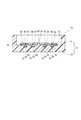
図1から図3に示すように、電子装置10は、センサカバー11、端子20、基板30、電気接続部40および導電性接着剤50などを備えている。本実施形態のセンサカバー11は、特許請求の範囲に記載の「筐体」の一例に相当する。
複数の端子20と、それに対応する複数の電気接続部40とは、導電性接着剤50によって電気的および機械的に接続している。
この固定方法では、先ず、センサカバー11に対し基板30が取り付けられる位置、又は、基板30の外周に、接着剤51を塗布する。さらに、センサカバー11の凹部15の底に露出した端子20の上、又は、基板30に設けられた複数の電気接続部40の上に導電性接着剤50を塗布する。
(1)本実施形態では、センサカバー11に固定された端子20と基板30の回路配線33とは、導電性接着剤50により電気的および機械的に接続される。そのため、電子装置10は、その端子20と基板30の回路配線33との間を接続するための配線部材等を用いることなく、部品点数を少なくし、構成を簡素にすると共に、体格を小型化することが可能である。さらに、電子装置10は、センサカバー11に基板30を取り付ける工程と、センサカバー11に固定された端子20と基板30の回路配線33とを接続する工程とを同時に行うことが可能である。したがって、電子装置10は、製造上のコストを低減することができる。
これにより、導電性接着剤50がセンサカバー11の凹部15の内側から外側へ漏れることが防がれる。したがって、電子装置10は、隣り合う電気接続部40と電気接続部40とが導電性接着剤50を介して短絡することを防ぐことができる。
これにより、基板30とセンサカバー11との隙間を小さくすることが可能である。したがって、電子装置10は、その体格を小型化することが可能である。
これにより、センサカバー11と基板30とはいずれも、基板用位置決めピン16を基準に熱膨張および熱収縮するものとなるので、導電性接着剤50に作用する応力が低減される。したがって、電子装置10は、導電性接着剤50による電気的接続の信頼性を高めることができる。
本発明の第2実施形態を図4および図5に示す。なお、図4では、説明のため、基板30を省略し、その外縁の位置のみを一点鎖線で示している。第2実施形態の電子装置10は、センサカバー11が有する凹部15に端子用位置決めピン17を備えている。端子用位置決めピン17は、センサカバー11と一体に形成されており、センサカバー11から延びて端子20が有する端子孔21に嵌合している。これにより、センサカバー11と端子20とはいずれも、端子用位置決めピン17を基準に熱膨張および熱収縮するものとなる。そのため、導電性接着剤50に作用する応力が低減される。
(1)上述した実施形態では、電子制御スロットル1が備えるスロットルバルブ2の回転角を検出する電子装置10について説明した。これに対し、他の実施形態では、電子装置10は、電子制御スロットル1に限らず、種々の装置に取り付けられるものであってもよい。
このように、本発明は、上述した実施形態に限定されるものではなく、発明の趣旨を逸脱しない範囲で種々の形態で実施可能である。
11・・・センサカバー(筐体)
20・・・端子
30・・・基板
33・・・回路配線
40・・・電気接続部
50・・・導電性接着剤
Claims (4)
- 筐体(11)と、
前記筐体に固定された端子(20)と、
少なくとも一部が前記端子に対面する位置で前記筐体に取り付けられる基板(30)と、
複数箇所に設けられており、前記基板が前記端子に対面する位置に形成された前記基板の回路配線(33)に固定され、前記回路配線から前記端子側へ突出する電気接続部(40)と、
前記端子と前記電気接続部とを固定し、電気的および機械的に接続する導電性接着剤(50)と、
隣り合う前記電気接続部と前記電気接続部との間に設けられ、前記筐体から延びて前記基板が有する基板孔(34)に嵌合する基板用位置決めピン(16)と、
を備え、
前記筐体と前記基板とは、前記基板用位置決めピンを基準に熱膨張および熱収縮する電子装置。 - 前記筐体は、前記端子と前記電気接続部とが接続する位置に凹部(15)を有し、
前記端子は、前記筐体が有する前記凹部の底に露出しており、
前記電気接続部は、前記基板の前記回路配線から前記凹部の内側へ突出しているものである請求項1に記載の電子装置。 - 前記基板は、前記筐体に対し接着剤(51)により固定されるものである請求項1または2に記載の電子装置。
- 前記端子と前記電気接続部とが導電性接着剤により接続する位置に設けられ、前記筐体から延びて前記端子が有する端子孔(21)に嵌合する端子用位置決めピン(17)をさらに備える請求項1から3のいずれか一項に記載の電子装置。
Priority Applications (2)
| Application Number | Priority Date | Filing Date | Title |
|---|---|---|---|
| JP2015238372A JP6561808B2 (ja) | 2015-12-07 | 2015-12-07 | 電子装置 |
| US15/368,747 US9974196B2 (en) | 2015-12-07 | 2016-12-05 | Electronic device |
Applications Claiming Priority (1)
| Application Number | Priority Date | Filing Date | Title |
|---|---|---|---|
| JP2015238372A JP6561808B2 (ja) | 2015-12-07 | 2015-12-07 | 電子装置 |
Publications (2)
| Publication Number | Publication Date |
|---|---|
| JP2017107899A JP2017107899A (ja) | 2017-06-15 |
| JP6561808B2 true JP6561808B2 (ja) | 2019-08-21 |
Family
ID=58800454
Family Applications (1)
| Application Number | Title | Priority Date | Filing Date |
|---|---|---|---|
| JP2015238372A Active JP6561808B2 (ja) | 2015-12-07 | 2015-12-07 | 電子装置 |
Country Status (2)
| Country | Link |
|---|---|
| US (1) | US9974196B2 (ja) |
| JP (1) | JP6561808B2 (ja) |
Family Cites Families (13)
| Publication number | Priority date | Publication date | Assignee | Title |
|---|---|---|---|---|
| EP0312740B1 (de) * | 1987-09-24 | 1991-10-30 | Siemens Aktiengesellschaft | Druckwandler mit einer Schaltungsplatine, insbesondere zur Steuerung eines Kraftfahrzeugs |
| JPH09107186A (ja) * | 1995-10-12 | 1997-04-22 | Matsushita Electric Ind Co Ltd | 電子部品とその製造方法 |
| JP2001124509A (ja) * | 1999-10-22 | 2001-05-11 | Aisan Ind Co Ltd | ロータリポジションセンサ |
| JP2001289610A (ja) * | 1999-11-01 | 2001-10-19 | Denso Corp | 回転角度検出装置 |
| US6466447B2 (en) * | 2000-02-24 | 2002-10-15 | Denso Corporation | Electronic control unit having flexible wires connecting connector to circuit board |
| JP2003264386A (ja) * | 2002-03-07 | 2003-09-19 | Denso Corp | 電子制御機器 |
| DE102004022325A1 (de) * | 2003-05-08 | 2004-12-09 | Aisan Kogyo K.K., Obu | Drosselregelungseinrichtungen |
| JP2011103367A (ja) * | 2009-11-11 | 2011-05-26 | Mitsubishi Electric Corp | 電力用半導体装置 |
| JP2011159081A (ja) * | 2010-01-29 | 2011-08-18 | Toshiba Corp | 電子機器 |
| JP5450511B2 (ja) | 2011-05-27 | 2014-03-26 | 日立オートモティブシステムズ株式会社 | インダクタンス式回転角度検出装置及びそれを備えたモータ駆動式の絞り弁制御装置 |
| US9223424B2 (en) * | 2013-04-08 | 2015-12-29 | Apple Inc. | Electronic device signal routing structures with conductive adhesive |
| JP6286884B2 (ja) * | 2013-06-13 | 2018-03-07 | セイコーエプソン株式会社 | 電子デバイス、電子機器、および移動体 |
| JP5943007B2 (ja) * | 2014-01-14 | 2016-06-29 | 株式会社デンソー | センサモジュール |
-
2015
- 2015-12-07 JP JP2015238372A patent/JP6561808B2/ja active Active
-
2016
- 2016-12-05 US US15/368,747 patent/US9974196B2/en not_active Expired - Fee Related
Also Published As
| Publication number | Publication date |
|---|---|
| US20170164492A1 (en) | 2017-06-08 |
| JP2017107899A (ja) | 2017-06-15 |
| US9974196B2 (en) | 2018-05-15 |
Similar Documents
| Publication | Publication Date | Title |
|---|---|---|
| JP5744092B2 (ja) | 電子制御装置および電子制御装置の製造方法 | |
| JP6117661B2 (ja) | 電子制御装置 | |
| KR101729809B1 (ko) | 전자 제어 장치 | |
| JP5223899B2 (ja) | 回転角検出装置 | |
| CN101558285A (zh) | 用于制造具有角度传感器的支承部件的方法 | |
| JP2010531987A (ja) | 位置センサを備えた制御装置 | |
| JP2007010514A (ja) | 非接触式の回転角度検出装置とその製造方法及びそれを用いたスロットル弁制御装置 | |
| CN102844644A (zh) | 电感式旋转角度检测装置及其安装方法 | |
| JPWO2003081087A1 (ja) | シフト位置検出装置付制御装置およびこれを備えたパワートレイン | |
| JP4794769B2 (ja) | エンジン制御装置、ECU(ElectronicControlUnit)およびECUケース | |
| JP4207753B2 (ja) | 電気回路機器の樹脂筐体構造 | |
| CN101680776B (zh) | 节气门位置传感器组件 | |
| JP2018031762A (ja) | 位置検出装置 | |
| JP6295354B2 (ja) | 電子制御装置 | |
| CN110383960A (zh) | 电子控制模块和用于制造电子控制模块的方法 | |
| JP6099915B2 (ja) | 電子制御装置 | |
| JP6561808B2 (ja) | 電子装置 | |
| JP5123710B2 (ja) | 回転検出装置および回転検出装置の製造方法 | |
| US20180102473A1 (en) | Sensor and method for producing same | |
| WO2018037962A1 (ja) | 位置検出装置 | |
| CN107923770B (zh) | 磁场检测装置 | |
| JP5920628B2 (ja) | センサモジュール | |
| JP4879711B2 (ja) | 回転角センサ及びスロットル装置 | |
| JP2008128646A (ja) | 回転角センサ及びスロットル装置 | |
| JP7041546B2 (ja) | 電子制御装置、及び電動駆動装置 |
Legal Events
| Date | Code | Title | Description |
|---|---|---|---|
| A621 | Written request for application examination |
Free format text: JAPANESE INTERMEDIATE CODE: A621 Effective date: 20180227 |
|
| A977 | Report on retrieval |
Free format text: JAPANESE INTERMEDIATE CODE: A971007 Effective date: 20181129 |
|
| A131 | Notification of reasons for refusal |
Free format text: JAPANESE INTERMEDIATE CODE: A131 Effective date: 20181225 |
|
| A521 | Request for written amendment filed |
Free format text: JAPANESE INTERMEDIATE CODE: A523 Effective date: 20190213 |
|
| TRDD | Decision of grant or rejection written | ||
| A01 | Written decision to grant a patent or to grant a registration (utility model) |
Free format text: JAPANESE INTERMEDIATE CODE: A01 Effective date: 20190625 |
|
| A61 | First payment of annual fees (during grant procedure) |
Free format text: JAPANESE INTERMEDIATE CODE: A61 Effective date: 20190708 |
|
| R151 | Written notification of patent or utility model registration |
Ref document number: 6561808 Country of ref document: JP Free format text: JAPANESE INTERMEDIATE CODE: R151 |
|
| R250 | Receipt of annual fees |
Free format text: JAPANESE INTERMEDIATE CODE: R250 |
|
| R250 | Receipt of annual fees |
Free format text: JAPANESE INTERMEDIATE CODE: R250 |
|
| R250 | Receipt of annual fees |
Free format text: JAPANESE INTERMEDIATE CODE: R250 |
|
| R250 | Receipt of annual fees |
Free format text: JAPANESE INTERMEDIATE CODE: R250 |