JP6430329B2 - Cutting apparatus and cutting method - Google Patents
Cutting apparatus and cutting method Download PDFInfo
- Publication number
- JP6430329B2 JP6430329B2 JP2015098196A JP2015098196A JP6430329B2 JP 6430329 B2 JP6430329 B2 JP 6430329B2 JP 2015098196 A JP2015098196 A JP 2015098196A JP 2015098196 A JP2015098196 A JP 2015098196A JP 6430329 B2 JP6430329 B2 JP 6430329B2
- Authority
- JP
- Japan
- Prior art keywords
- rotary blade
- fixing member
- cutting
- recess
- flange
- Prior art date
- Legal status (The legal status is an assumption and is not a legal conclusion. Google has not performed a legal analysis and makes no representation as to the accuracy of the status listed.)
- Active
Links
Images


Classifications
-
- B—PERFORMING OPERATIONS; TRANSPORTING
- B26—HAND CUTTING TOOLS; CUTTING; SEVERING
- B26D—CUTTING; DETAILS COMMON TO MACHINES FOR PERFORATING, PUNCHING, CUTTING-OUT, STAMPING-OUT OR SEVERING
- B26D1/00—Cutting through work characterised by the nature or movement of the cutting member or particular materials not otherwise provided for; Apparatus or machines therefor; Cutting members therefor
- B26D1/01—Cutting through work characterised by the nature or movement of the cutting member or particular materials not otherwise provided for; Apparatus or machines therefor; Cutting members therefor involving a cutting member which does not travel with the work
- B26D1/12—Cutting through work characterised by the nature or movement of the cutting member or particular materials not otherwise provided for; Apparatus or machines therefor; Cutting members therefor involving a cutting member which does not travel with the work having a cutting member moving about an axis
- B26D1/14—Cutting through work characterised by the nature or movement of the cutting member or particular materials not otherwise provided for; Apparatus or machines therefor; Cutting members therefor involving a cutting member which does not travel with the work having a cutting member moving about an axis with a circular cutting member, e.g. disc cutter
-
- B—PERFORMING OPERATIONS; TRANSPORTING
- B26—HAND CUTTING TOOLS; CUTTING; SEVERING
- B26D—CUTTING; DETAILS COMMON TO MACHINES FOR PERFORATING, PUNCHING, CUTTING-OUT, STAMPING-OUT OR SEVERING
- B26D7/00—Details of apparatus for cutting, cutting-out, stamping-out, punching, perforating, or severing by means other than cutting
- B26D7/26—Means for mounting or adjusting the cutting member; Means for adjusting the stroke of the cutting member
- B26D7/2614—Means for mounting the cutting member
- B26D7/2621—Means for mounting the cutting member for circular cutters
-
- B—PERFORMING OPERATIONS; TRANSPORTING
- B26—HAND CUTTING TOOLS; CUTTING; SEVERING
- B26D—CUTTING; DETAILS COMMON TO MACHINES FOR PERFORATING, PUNCHING, CUTTING-OUT, STAMPING-OUT OR SEVERING
- B26D1/00—Cutting through work characterised by the nature or movement of the cutting member or particular materials not otherwise provided for; Apparatus or machines therefor; Cutting members therefor
- B26D1/0006—Cutting members therefor
-
- B—PERFORMING OPERATIONS; TRANSPORTING
- B26—HAND CUTTING TOOLS; CUTTING; SEVERING
- B26D—CUTTING; DETAILS COMMON TO MACHINES FOR PERFORATING, PUNCHING, CUTTING-OUT, STAMPING-OUT OR SEVERING
- B26D7/00—Details of apparatus for cutting, cutting-out, stamping-out, punching, perforating, or severing by means other than cutting
- B26D7/20—Cutting beds
-
- H—ELECTRICITY
- H01—ELECTRIC ELEMENTS
- H01L—SEMICONDUCTOR DEVICES NOT COVERED BY CLASS H10
- H01L21/00—Processes or apparatus adapted for the manufacture or treatment of semiconductor or solid state devices or of parts thereof
- H01L21/70—Manufacture or treatment of devices consisting of a plurality of solid state components formed in or on a common substrate or of parts thereof; Manufacture of integrated circuit devices or of parts thereof
- H01L21/77—Manufacture or treatment of devices consisting of a plurality of solid state components or integrated circuits formed in, or on, a common substrate
- H01L21/78—Manufacture or treatment of devices consisting of a plurality of solid state components or integrated circuits formed in, or on, a common substrate with subsequent division of the substrate into plural individual devices
-
- H—ELECTRICITY
- H05—ELECTRIC TECHNIQUES NOT OTHERWISE PROVIDED FOR
- H05K—PRINTED CIRCUITS; CASINGS OR CONSTRUCTIONAL DETAILS OF ELECTRIC APPARATUS; MANUFACTURE OF ASSEMBLAGES OF ELECTRICAL COMPONENTS
- H05K3/00—Apparatus or processes for manufacturing printed circuits
- H05K3/0011—Working of insulating substrates or insulating layers
- H05K3/0044—Mechanical working of the substrate, e.g. drilling or punching
- H05K3/0052—Depaneling, i.e. dividing a panel into circuit boards; Working of the edges of circuit boards
Description
本発明は、被切断物を切断することによって、個片化された複数の製品を製造する切断装置及び切断方法に関するものである。 The present invention relates to a cutting apparatus and a cutting method for manufacturing a plurality of separated products by cutting an object to be cut.
プリント基板やリードフレームなどからなる基板を格子状の複数の領域に仮想的に区画して、それぞれの領域にチップ状の素子(例えば、半導体チップ)を装着した後、基板全体を樹脂封止したものを封止済基板という。回転刃などを使用した切断機構によって封止済基板を切断し、それぞれの領域単位に個片化したものが製品になる。 A substrate composed of a printed circuit board, a lead frame, etc. is virtually divided into a plurality of grid-like areas, and chip-like elements (for example, semiconductor chips) are attached to the respective areas, and then the entire board is sealed with resin. This is called a sealed substrate. A product obtained by cutting a sealed substrate by a cutting mechanism using a rotary blade or the like and dividing it into individual regions is a product.
従来から、切断装置を使用して封止済基板の所定領域を回転刃などの切断機構によって切断している。まず、封止済基板を切断用テーブルの上に載置する。次に、封止済基板をアライメント(位置合わせ)する。アライメントすることによって、複数の領域を区切る仮想的な切断線の位置を設定する。次に、封止済基板を載置した切断用テーブルと切断機構とを相対的に移動させる。切削水を封止済基板の切断箇所に噴射するとともに、切断機構によって封止済基板に設定された切断線に沿って封止済基板を切断する。封止済基板を切断することによって、個片化された製品が製造される。 Conventionally, a predetermined region of a sealed substrate is cut by a cutting mechanism such as a rotary blade using a cutting device. First, the sealed substrate is placed on a cutting table. Next, the sealed substrate is aligned (positioned). By aligning, the position of a virtual cutting line that divides a plurality of regions is set. Next, the cutting table on which the sealed substrate is placed and the cutting mechanism are relatively moved. The cutting water is sprayed onto the cut portion of the sealed substrate, and the sealed substrate is cut along the cutting line set on the sealed substrate by the cutting mechanism. An individualized product is manufactured by cutting the sealed substrate.
切断機構として回転刃を有するスピンドルが使用される。スピンドルは回転刃を高速回転させることによって封止済基板を切断する。回転刃は、その両端を固定部材であるフランジによって挟まれ、スピンドルに設けられた回転軸の軸方向に対して直交する面に平行になるように取り付けられる。回転刃は、30,000〜50,000rpm程度に高速回転するので、回転刃の中心から外周方向に向かって遠心力が作用する。遠心力が大きくなると、遠心力によってフランジや回転刃に変位が発生する。回転刃が高速回転することによって、フランジや回転刃が遠心力によって変形する。回転刃が遠心力によって変形すると、回転軸の軸方向に対して直交する面から回転刃がずれてしまう。言い換えると、回転軸に直交する方向に対して回転刃が傾きを持つようになる。この回転刃のずれ量(傾き)がある程度以上に大きくなると、回転刃に破損が発生したり、回転刃の蛇行が発生したりする。 A spindle having a rotary blade is used as a cutting mechanism. The spindle cuts the sealed substrate by rotating the rotary blade at a high speed. The rotary blade is attached so that both ends thereof are sandwiched by flanges that are fixing members and are parallel to a plane orthogonal to the axial direction of the rotary shaft provided on the spindle. Since the rotary blade rotates at a high speed of about 30,000 to 50,000 rpm, a centrifugal force acts from the center of the rotary blade toward the outer periphery. When the centrifugal force increases, displacement occurs in the flange and the rotary blade due to the centrifugal force. When the rotary blade rotates at a high speed, the flange and the rotary blade are deformed by centrifugal force. When the rotary blade is deformed by centrifugal force, the rotary blade is displaced from a plane orthogonal to the axial direction of the rotary shaft. In other words, the rotary blade has an inclination with respect to the direction orthogonal to the rotation axis. If the amount of deviation (inclination) of the rotary blade becomes larger than a certain level, the rotary blade may be damaged or the rotary blade may meander.
切削装置において、「ワッシャ状の切削ブレードは、2つのフランジに挟持された状態でスピンドル先端にナットによって固定されている。ブレードは、フランジに接触した状態で固定されるため、フランジのブレードに接触する端面とスピンドルの回転中心線とのなす角度が90度でないと、スピンドル回転時にフランジが端面ブレを生じてしまい、精密な加工ができなくなってしまう」ことが開示されている(例えば、特許文献1の段落〔0003〕、〔0004〕、図3参照)。 In the cutting device, “the washer-shaped cutting blade is fixed to the spindle tip by a nut while being sandwiched between two flanges. Since the blade is fixed in contact with the flange, it contacts the blade of the flange. If the angle between the end surface to be rotated and the rotation center line of the spindle is not 90 degrees, the flange will end up blurring at the time of spindle rotation, and precise processing cannot be performed "(for example, Patent Documents). 1 paragraphs [0003] and [0004], see FIG. 3).
特許文献1に開示された技術によれば、ブレード31およびフランジ37をフランジ36に嵌合させ、ブレード31を一対のフランジ36,37によって挟持させる。さらに、ナット35の雌ねじ部35aをフランジ36のフランジ雄ねじ部36aに螺合させて締め付けることで、ブレード31はフランジ36,37の外周面寄りの端面36c,37aによって挟持固定される(特許文献1の段落〔0020〕、図3)。
According to the technique disclosed in
この技術によれば、ブレード31はフランジ36,37の外周面寄りの端面36c,37aによって固定される。フランジ36とフランジ37とではその構造や重量が異なる。したがって、遠心力によって受ける力が、フランジ36とフランジ37とでは異なる。ブレード31が高速回転すると、遠心力によってフランジ36とフランジ37とに作用する力が異なるため、ブレード31が変形するおそれがある。 According to this technique, the blade 31 is fixed by the end surfaces 36c and 37a near the outer peripheral surfaces of the flanges 36 and 37. The structure and weight of the flange 36 and the flange 37 are different. Therefore, the force received by the centrifugal force differs between the flange 36 and the flange 37. When the blade 31 rotates at a high speed, the force acting on the flange 36 and the flange 37 differs depending on the centrifugal force, so that the blade 31 may be deformed.
本発明は、回転刃を挟んで固定する第1の固定部材及び第2の固定部材の構造を最適化し、それぞれ遠心力に起因して発生する第1の固定部材の変位量と第2の固定部材の変位量とを等しくすることによって、回転刃の変形や破損を防止することができる切断装置及び切断方法を提供することを目的とする。 The present invention optimizes the structures of the first fixing member and the second fixing member that are fixed with the rotary blade interposed therebetween, and the displacement amount of the first fixing member and the second fixing caused by the centrifugal force, respectively. It is an object of the present invention to provide a cutting device and a cutting method capable of preventing deformation and breakage of the rotary blade by making the displacement amount of the member equal.
上記の課題を解決するために、本発明に係る切断装置は、被切断物が載置されるテーブルと、被切断物を切断する切断機構と、テーブルと切断機構とを相対的に移動させる移動機構とを備え、被切断物を切断することによって複数の製品を製造する際に使用される切断装置であって、切断機構に設けられた回転軸と、回転軸に対して固定された円板状の回転刃と、回転刃における切断機構の本体に近い側に位置する第1の面に部分的に密着する第1の固定部材と、第1の固定部材の外周部に設けられ回転刃の第1の面に密着する第1の保持部と、第1の固定部材に設けられた第1の凹部と、第1の凹部の少なくとも一部に重なるようにして第1の固定部材に設けられ、第1の凹部の深さよりも大きい深さを有する深い凹部と、第1の固定部材に設けられた第1のサポート部と、回転刃の第2の面に部分的に密着する第2の固定部材と、第2の固定部材の外周部に設けられ回転刃の第2の面に密着する第2の保持部と、第2の固定部材に設けられた第2の凹部と、第2の固定部材に設けられた第2のサポート部とを備え、第1の固定部材と第2の固定部材とによって回転刃が挟まれた状態において回転刃が回転軸に対して固定され、回転刃を間に置いて第2の凹部が第1の凹部と深い凹部とに相対向して配置され、回転刃が回転することによって発生する遠心力に起因する回転刃の変形が抑制されることを特徴とする。 In order to solve the above problems, a cutting apparatus according to the present invention includes a table on which a workpiece is placed, a cutting mechanism that cuts the workpiece, and a movement that relatively moves the table and the cutting mechanism. A cutting device having a mechanism and used when manufacturing a plurality of products by cutting a workpiece, a rotating shaft provided in the cutting mechanism, and a disc fixed to the rotating shaft A rotary blade, a first fixing member that is partially in close contact with the first surface of the rotary blade that is located closer to the main body of the cutting mechanism, and an outer peripheral portion of the first fixing member that is provided on the outer periphery of the rotary blade. The first holding member that is in close contact with the first surface, the first concave portion provided in the first fixing member, and the first fixing member so as to overlap at least part of the first concave portion. A deep recess having a depth greater than the depth of the first recess, and the first fixing member A first support portion provided, a second fixing member that is partially in close contact with the second surface of the rotary blade, and an outer peripheral portion of the second fixed member that is in close contact with the second surface of the rotary blade A second holding portion, a second recess provided in the second fixing member, and a second support portion provided in the second fixing member, the first fixing member and the second fixing portion In a state where the rotary blade is sandwiched between the fixing members, the rotary blade is fixed to the rotary shaft, and the second concave portion is disposed opposite to the first concave portion and the deep concave portion with the rotary blade interposed therebetween. The deformation of the rotary blade due to the centrifugal force generated by the rotation of the rotary blade is suppressed.
本発明に係る切断装置は、上述の切断装置において、第1の保持部と第1の凹部と深い凹部と第1のサポート部とが円周状に形成され、第2の保持部と第2の凹部と第2のサポート部とが円周状に形成されることを特徴とする。 In the cutting device according to the present invention, in the above-described cutting device, the first holding portion, the first concave portion, the deep concave portion, and the first support portion are formed in a circumferential shape, and the second holding portion and the second holding portion are formed. The concave portion and the second support portion are formed in a circumferential shape.
本発明に係る切断装置は、上述の切断装置において、深い凹部の深さは第1の凹部の深さ及び第2の凹部の深さよりも大きいことを特徴とする。 The cutting device according to the present invention is characterized in that, in the above-described cutting device, the depth of the deep recess is larger than the depth of the first recess and the depth of the second recess.
本発明に係る切断装置は、上述の切断装置において、第1のサポート部は第1の固定部材における回転軸に近い側に設けられ、第2のサポート部は第2の固定部材における回転軸に近い側に設けられ、回転刃を間に置いて第1のサポート部と第2のサポート部とが相対向して配置され、回転刃の第1の面から第1のサポート部の端面までの第1の距離と回転刃の第2の面から第2のサポート部の端面までの第2の距離とが等しい所定の距離であり、所定の距離は回転刃が有する砥粒の最大径よりも大きく、回転刃の変形が許容される範囲における変形量の最大値よりも小さいことを特徴とする。 In the cutting device according to the present invention, in the above-described cutting device, the first support portion is provided on a side near the rotation shaft of the first fixing member, and the second support portion is on the rotation shaft of the second fixing member. The first support part and the second support part are arranged opposite to each other with the rotary blade in between, and are arranged from the first surface of the rotary blade to the end surface of the first support part. The first distance and the second distance from the second surface of the rotary blade to the end surface of the second support part are equal to each other, and the predetermined distance is larger than the maximum diameter of the abrasive grains of the rotary blade. It is large and smaller than the maximum value of the deformation amount in the range where the deformation of the rotary blade is allowed.
本発明に係る切断装置は、上述の切断装置において、深い凹部は、第1の固定部材において、回転刃の第1の面に相対向する面又は相対向する面の反対面のうち少なくとも一方において設けられることを特徴とする。 The cutting device according to the present invention is the above-described cutting device, wherein the deep recess is at least one of a surface facing the first surface of the rotary blade or a surface opposite to the surface facing the first fixing member. It is provided.
本発明に係る切断装置は、上述の切断装置において、被切断物は封止済基板であることを特徴とする。 The cutting apparatus according to the present invention is characterized in that, in the above-described cutting apparatus, the object to be cut is a sealed substrate.
本発明に係る切断装置は、上述の切断装置において、被切断物は、複数の製品にそれぞれ対応する複数の領域においてそれぞれ機能素子が作りこまれた基板であることを特徴とする。 The cutting device according to the present invention is characterized in that, in the above-described cutting device, the object to be cut is a substrate in which functional elements are formed in a plurality of regions respectively corresponding to a plurality of products.
上記の課題を解決するために、本発明に係る切断方法は、被切断物をテーブルに載置する工程と、回転軸に固定された円板状の回転刃と被切断物とを相対的に移動させる工程とを備え、被切断物を切断することによって複数の製品を製造する切断方法であって、第1の保持部と、第1の凹部と、第1の凹部に重なるようにして設けられ第1の凹部の深さよりも大きい深さを有する深い凹部と、第1のサポート部とを有する第1の固定部材を準備する工程と、第2の保持部と、第2の凹部と、第2のサポート部とを有する第2の固定部材を準備する工程と、第1の固定部材と第2の固定部材とによって挟まれた状態において回転軸に固定された回転刃を準備する工程と、回転刃を回転させる工程とを備え、準備された第1の固定部材において第1の保持部が外周部に設けられ、準備された第2の固定部材において第2の保持部が外周部に設けられ、回転刃を準備する工程では、第2の凹部を第1の凹部と深い凹部とに相対向して配置し、回転刃における切断機構の本体に近い側に位置する第1の面に第1の保持部を密着させ、回転刃の第2の面に第2の保持部を密着させ、回転刃を回転させる工程では、回転刃が回転することによって発生する遠心力に起因する回転刃の変形を抑制することを特徴とする。 In order to solve the above-described problems, a cutting method according to the present invention includes a step of placing an object to be cut on a table, a disk-shaped rotary blade fixed to a rotating shaft, and the object to be cut. A cutting method for manufacturing a plurality of products by cutting an object to be cut, wherein the first holding portion, the first recess, and the first recess are provided so as to overlap with each other. A step of preparing a first fixing member having a deep recess having a depth larger than the depth of the first recess, and a first support portion, a second holding portion, and a second recess, A step of preparing a second fixing member having a second support portion; a step of preparing a rotary blade fixed to the rotary shaft in a state sandwiched between the first fixing member and the second fixing member; A step of rotating the rotary blade, and a first fixing member prepared The second holding member is provided on the outer peripheral portion in the prepared second fixing member, and in the step of preparing the rotary blade, the second concave portion is deep with the first concave portion. The first holding portion is disposed in opposition to the concave portion, the first holding portion is brought into close contact with the first surface located on the side closer to the main body of the cutting mechanism in the rotary blade, and the second holding portion is provided on the second surface of the rotary blade. In the step of rotating the rotary blade, the deformation of the rotary blade due to the centrifugal force generated by the rotation of the rotary blade is suppressed.
本発明に係る切断方法は、上述の切断方法において、準備された第1の固定部材において、第1の保持部と、第1の凹部と、深い凹部と、第1のサポート部とが円周状に形成され、準備された第2の固定部材において、第2の保持部と、第2の凹部と、第2のサポート部とが円周状に形成されることを特徴とする。 In the cutting method according to the present invention, in the above-described cutting method, in the first fixing member prepared, the first holding portion, the first concave portion, the deep concave portion, and the first support portion are circumferential. In the second fixing member formed and prepared in a shape, the second holding portion, the second concave portion, and the second support portion are formed in a circumferential shape.
本発明に係る切断方法は、上述の切断方法において、それぞれ準備された第1の固定部材と第2の固定部材とにおいて、深い凹部の深さは第1の凹部の深さ及び第2の凹部の深さよりも大きいことを特徴とする。 The cutting method according to the present invention is the above-described cutting method. In the first fixing member and the second fixing member respectively prepared, the depth of the deep recess is the depth of the first recess and the second recess. It is characterized by being larger than the depth of.
本発明に係る切断方法は、上述の切断方法において、それぞれ準備された第1の固定部材と第2の固定部材とにおいて、第1のサポート部は第1の固定部材における回転軸に近い側に設けられ、第2のサポート部は第2の固定部材における回転軸に近い側に設けられ、回転刃を間に置いて第1のサポート部と第2のサポート部とが相対向して配置され、回転刃の第1の面から第1のサポート部の端面までの第1の距離と回転刃の第2の面から第2のサポート部の端面までの第2の距離とが等しい所定の距離であり、所定の距離は回転刃が有する砥粒の最大径よりも大きく、回転刃の変形が許容される範囲における変形量の最大値よりも小さいことを特徴とする。 In the cutting method according to the present invention, in the above-described cutting method, in the first fixing member and the second fixing member respectively prepared, the first support portion is closer to the rotating shaft in the first fixing member. The second support part is provided on the side of the second fixed member close to the rotation axis, and the first support part and the second support part are arranged to face each other with the rotary blade in between. The predetermined distance from which the 1st distance from the 1st surface of a rotary blade to the end surface of the 1st support part and the 2nd distance from the 2nd surface of a rotary blade to the end surface of the 2nd support part are equal The predetermined distance is larger than the maximum diameter of the abrasive grains of the rotary blade and smaller than the maximum value of the deformation amount in a range where the deformation of the rotary blade is allowed.
本発明に係る切断方法は、上述の切断方法において、準備された第1の固定部材において、深い凹部は、回転刃の第1の面に相対向する面又は相対向する面の反対面のうち少なくとも一方において設けられることを特徴とする。 In the cutting method according to the present invention, in the above-described cutting method, in the prepared first fixing member, the deep recess is a surface facing the first surface of the rotary blade or a surface opposite to the surface facing the rotating blade. It is provided in at least one.
本発明に係る切断方法は、上述の切断方法において、被切断物は封止済基板であることを特徴とする。 The cutting method according to the present invention is characterized in that, in the above-described cutting method, the object to be cut is a sealed substrate.
本発明に係る切断方法は、上述の切断方法において、被切断物は、複数の製品にそれぞれ対応する複数の領域においてそれぞれ機能素子が作りこまれた基板であることを特徴とする。 The cutting method according to the present invention is characterized in that, in the above-described cutting method, the object to be cut is a substrate in which functional elements are formed in a plurality of regions respectively corresponding to a plurality of products.
本発明によれば、切断機構に、回転軸と、回転軸に固定された回転刃と、回転刃を両側から挟んで固定する第1の固定部材及び第2の固定部材とを設ける。第1の固定部材には、回転刃の第1の面に部分的に密着する第1の保持部と、第1の凹部と、第1の凹部の少なくとも一部に重なるようにして設けられ第1の凹部の深さよりも大きい深さを有する深い凹部と、第1のサポート部とを設ける。第2の固定部材には、回転刃の第2の面に部分的に密着する第2の保持部と、第2の凹部と、第2のサポート部とを設ける。回転刃を間に置いて第2の凹部を第1の凹部と深い凹部とに相対向して配置することによって、回転刃が回転することによって発生する遠心力に起因する回転刃の変形を抑制する。したがって、回転刃が高速回転した場合であっても、遠心力に起因して発生する回転刃の振動、破損、蛇行などを防止することができる。 According to the present invention, the cutting mechanism is provided with the rotary shaft, the rotary blade fixed to the rotary shaft, and the first fixing member and the second fixing member that fix the rotary blade sandwiched from both sides. The first fixing member is provided so as to overlap at least a part of the first holding portion, the first concave portion, and the first concave portion that are partially in close contact with the first surface of the rotary blade. A deep concave portion having a depth larger than the depth of the first concave portion and a first support portion are provided. The second fixing member is provided with a second holding portion that is partially in close contact with the second surface of the rotary blade, a second recess, and a second support portion. Suppressing deformation of the rotary blade due to the centrifugal force generated by the rotation of the rotary blade by arranging the second concave portion opposite to the first concave portion and the deep concave portion with the rotary blade interposed therebetween. To do. Therefore, even when the rotary blade rotates at high speed, vibration, breakage, meandering, etc. of the rotary blade caused by centrifugal force can be prevented.
図4に示されるように、スピンドル7に、回転軸8と、回転軸8に固定された回転刃9と、回転刃9を両側から挟んで固定する第1フランジ15及び第2フランジ16とを設ける。第1フランジ15には、それぞれ円周状に形成された第1の凹部21と深い凹部20とを設ける。第2フランジ16には、円周状に形成された第2の凹部25を設ける。回転刃9を間に置いて第2の凹部25を第1の凹部21と深い凹部20とに相対向して配置する。深い凹部20を設けることによって、遠心力に起因して発生する第1フランジ15の変位量と第2フランジ16の変位量とを等しくする。このことによって、それぞれのフランジが反対側のフランジに向かって回転刃9を押そうとする力を相殺することができる。したがって、回転刃9が高速回転した場合であっても、遠心力に起因して発生する回転刃9の振動、破損、蛇行などを防止することができる。
As shown in FIG. 4, the
本発明に係る切断装置について、図1を参照して説明する。本出願書類におけるいずれの図についても、わかりやすくするために、適宜省略し又は誇張して模式的に描かれている。同一の構成要素については、同一の符号を付して説明を適宜省略する。 A cutting apparatus according to the present invention will be described with reference to FIG. Any figure in the present application document is schematically omitted or exaggerated as appropriate for easy understanding. About the same component, the same code | symbol is attached | subjected and description is abbreviate | omitted suitably.
図1に示されるように、切断装置1は、被切断物を複数の製品に個片化する装置である。切断装置1は、基板供給モジュールAと基板切断モジュールBと検査モジュールCとを、それぞれ構成要素として備える。各構成要素(各モジュールA〜C)は、それぞれ他の構成要素に対して着脱可能かつ交換可能である。
As shown in FIG. 1, the
基板供給モジュールAには、被切断物に相当する封止済基板2を供給する基板供給機構3と、切断装置1の動作や制御などを行う制御部CTLとが設けられる。封止済基板2は、プリント基板やリードフレームなどからなる基板と、基板が有する複数の領域に装着された複数の機能素子(半導体素子などのチップ)と、複数の領域が一括して覆われるようにして形成された封止樹脂とを有する。封止済基板2は、最終的に切断されて個片化される被切断物である。封止済基板2は、搬送機構(図示なし)によって基板切断モジュールBに搬送される。
The substrate supply module A is provided with a
図1に示される切断装置1は、シングルカットテーブル方式の切断装置である。したがって、基板切断モジュールBには、1個の切断用テーブル4が設けられる。切断用テーブル4は、移動機構5によって図のY方向に移動可能であり、かつ、回転機構6によってθ方向に回動可能である。切断用テーブル4には切断用治具(図示なし)が取り付けられ、切断用治具の上に封止済基板2が載置される。
The
基板切断モジュールBには、切断機構としてスピンドル7が設けられる。図1に示される切断装置1は、1個のスピンドル7が設けられるシングルスピンドル構成の切断装置である。スピンドル7は、独立してX方向とZ方向とに移動可能である。スピンドル7は、回転軸8と回転軸8の先端部に装着された回転刃9とを備える。回転刃9は、回転軸8の軸方向(X方向)に対して直交する面(Y軸とZ軸とを含む面)に平行になるように取り付けられる。スピンドル7には、高速回転する回転刃9によって発生する摩擦熱を抑えるために切削水を噴射する切削水用ノズル(図示なし)が設けられる。切断用テーブル4とスピンドル7とを相対的に移動させることによって封止済基板2が切断される。回転刃8は、Y軸とZ軸とを含む面内において回転することによって封止済基板2を切断する。
The substrate cutting module B is provided with a
検査モジュールCには検査用テーブル10が設けられる。検査用テーブル10には、封止済基板2を切断して個片化された複数の製品Pからなる集合体、すなわち、切断済基板11が載置される。複数の製品Pは、検査用のカメラ(図示なし)によって検査されて、良品と不良品とに選別される。良品はトレイ12に収容される。
The inspection module C is provided with an inspection table 10. On the inspection table 10, an aggregate made up of a plurality of products P cut into pieces by cutting the sealed
実施例1おいては、シングルカットテーブル方式であって、シングルスピンドル構成の切断装置1を説明した。これに限らず、シングルカットテーブル方式であって、ツインスピンドル構成の切断装置や、ツインカットテーブル方式であって、ツインスピンドル構成の切断装置などを使用してもよい。
In the first embodiment, the single-cut table
図2〜図5を参照して、本発明に係る切断装置1において使用されるスピンドル7を説明する。図2に示される切断機構であるスピンドル7は、スピンドル本体部13と駆動機構であるスピンドルモータ14とスピンドルモータ14に接続された回転軸8とを備える。回転軸8は、ラジアルエアベアリングとアキシャルエアベアリング(図示なし)とから吹き出される空気(エア)によって非接触の状態でスピンドル7に回転可能に支持される。回転軸8の先端部には封止済基板2を切断する回転刃9が装着される。回転刃9は、回転軸8の軸方向(X方向)に対して直交する面(Y軸とZ軸とを含む面)に平行になるように取り付けられる。回転刃9は、固定部材である第1フランジ15と第2フランジ16とによって両側を挟まれ、回転軸8に取り付けられる。回転刃9は、貫通孔を有するワッシャータイプの回転刃である。回転刃9は、スピンドル7に着脱可能で交換することができる。
The
図3を参照して、本実施例において使用されるスピンドル7の構成部材について説明する。図3に示されるように、スピンドル7に設けられた回転軸8は、その先端に第1フランジ15を取り付けるため口径の小さい先端部8aを有する。回転軸8の先端部8aには、第1フランジ15を回転軸8に固定するためのボルト17と螺合する雌ねじ部8iが形成されている。
With reference to FIG. 3, the components of the
第1フランジ15は、第2フランジ16と共に回転刃9を挟んで保持し、回転刃9をスピンドル7に固定する部材である。第1フランジ15は、回転刃9の背面側(スピンドル7側;第1の面側)に配置される後側フランジであり、回転軸8に直接取り付けられる。第1フランジ15の中心部には、回転軸8の先端部8aに嵌合される貫通穴19が設けられる。第1フランジ15は、回転刃9が挿入される筒状のベース部15aと、第2フランジ16が嵌合される筒状のベース部15bと、回転刃9を保持する円周状の保持部15cと、回転刃9の傾きや反りを抑制するための円周状のサポート部15dと、第1フランジ15の変位(変形)を抑制するために円周状に形成された深い凹部20と、第1フランジ15の変位(変形)を抑制するために円周状に形成された第1の凹部21とを備える。深い凹部20と第1の凹部21とは円周状に形成される。第1フランジ15の中心先端部には、ボルト17が締結される凹部22とナット18に螺合するナット雄ねじ部15eとが形成されている。
The
図3の上方又は下方から見た場合において、深い凹部20は第1の凹部21の少なくとも一部に重なるようにして設けられる。言い換えれば、図3において、円周状に形成された深い凹部20は、円周状に形成された第1の凹部21の少なくとも一部に、平面視して含まれる。本出願書類において、「円周状に形成された」という文言は、円周状に切れ目なく形成された場合と、円周状であって少なくとも1か所以上の切れ目を有するようにして形成された場合との双方を含む。
When viewed from above or below in FIG. 3, the
図3に示されるように、第1フランジ15において、深い凹部20は第1の凹部21と同じ側(図の下側)に設けられる。これに限定されるものではなく、第1フランジ15において、深い凹部20は、第1の凹部21の反対側(図の上側)に設けられてもよい。第1フランジ15において、深い凹部20は、第1の凹部21と同じ側と反対側との双方に設けられてもよい。
As shown in FIG. 3, in the
回転刃9は、貫通孔23を備えリング状に形成されたワッシャータイプの回転刃である。回転刃9の貫通孔23は、第1フランジの筒状のベース部15aに挿入される。回転刃9は、例えば、ダイヤモンドなどの砥粒を、金属、樹脂、セラミックなどの結合材で結合した円環状の砥石からなる回転刃である。封止済基板を切断する際に使用される砥粒としては、数μm〜数十μm程度の粒径を有するダイヤモンド砥粒が使用されることが多い。
The
第2フランジ16は、第1フランジ15と共に回転刃9を挟んで保持し、回転刃9をスピンドル7に固定する部材である。第2フランジ16は、回転刃9の前面側(スピンドル7とは反対側;第2の面側)に配置される前側フランジであり、第1フランジ15に嵌合される。第2フランジ16の中心部には、第1フランジ15の筒状のベース部15bに嵌合される貫通穴24が設けられる。第2フランジ16は、回転刃9を保持する円周状の保持部16cと、回転刃9の傾きや反りを抑制するための円周状のサポート部16dと、第2フランジ16の変位(変形)を抑制するために円周状に形成された第2の凹部25とを備える。
The
回転刃9は、第1フランジ15の外周部に設けられた円周状の保持部15cと第2フランジ16の外周部に設けられた円周状の保持部16cとによって挟まれ、保持される。回転刃9を、回転軸8の軸方向に対して直交する面に平行になるように保持する。回転刃9を精度よく保持するために、保持部15c及び保持部16cの端面はそれぞれ高い平坦性を有する。
The
ナット18は、第2フランジ16を第1フランジ15に固定するためのフランジナットである。ナット18の内周面にはナット雌ねじ部18iが形成されている。ナット18を第1フランジ15のナット雄ねじ部15eに締結することによって、回転刃9は第1フランジ15と第2フランジ16とによって挟まれ固定される。
The nut 18 is a flange nut for fixing the
ボルト17は、回転刃9を挟んでナット18によって固定された第1フランジ15及び第2フランジ16を回転軸8に固定するための固定部材である。ボルト17には、回転軸8の雌ねじ部8iに螺合する雄ねじ部17eが形成されている。ボルト17の頭には、ボルト17を回転軸8に対して締結する際に又は回転軸8から緩める際に回転させるために、例えば、六角穴26が形成されている。
The
図3を参照して、スピンドル7に回転刃9を装着する手順について説明する。まず、回転刃9の貫通孔23を、第1フランジ15の筒状のベース部15aに挿入する。次に、第2フランジ16の貫通穴24を第1フランジ15の筒状のベース部15bに嵌合する。更に、ナット18のナット雌ねじ部18iを、第1フランジ15の先端部に形成されたナット雄ねじ部15eに螺合させて締め付ける。このことによって、回転刃9は、第1フランジ15と第2フランジ16とによって挟まれて固定される。
With reference to FIG. 3, the procedure for mounting the
次に、第1フランジ15と第2フランジ16とによって回転刃9を固定した状態で、第1フランジ15の中心部に形成された貫通穴19を、スピンドル7の回転軸8の先端部8aに嵌合する。次に、ボルト17を、回転軸8の先端部8aに形成された雌ねじ部8iに螺合させて締め付ける。ボルト17の頭に形成された六角穴26に、例えば、L型レンチなどを挿入してボルト17を締め付ける。ボルト17を回転軸8に締結することによって、第1フランジ15と第2フランジ16とによって固定された回転刃9を、スピンドル7の回転軸8に取り付ける。
Next, in a state where the
図4を参照して、スピンドル7に回転刃9が装着された状態を説明する。図4は、本発明に係る切断装置1において使用されるスピンドル7を示している。図4に示されるように、第1フランジ15と第2フランジ16とによって挟まれ、ナット18によって固定された回転刃9が、ボルト17によって回転軸8に取り付けられる。回転刃9は、第1フランジ15の外周部に形成された保持部15cと第2フランジ16の外周部に形成された保持部16cとによって、挟まれ固定される。保持部15cと保持部16cとは、回転刃9の取り付け状態を安定に維持するために、それぞれ高い平坦性を有する。保持部15cと保持部16cとによって挟まれ固定された回転刃9が、高速回転することによって封止済基板2を切断する。
With reference to FIG. 4, a state where the
スピンドル7に回転刃9を装着する手順については、本実施例及び従来の技術とも全く同じ手順で行われる。ここでは、従来の技術における第1フランジ15と第2フランジ16とを使用した際の課題について説明する。従来の技術において、回転刃9が高速回転していないアイドリング状態又は静止状態においては、回転刃9は回転軸8の軸方向に対して直交する面に平行に位置する。回転刃9が高速回転することによって、第1フランジ15と第2フランジ16とは回転することによる遠心力をそれぞれ受ける。遠心力は回転刃9の中心から径方向(外側)に向かって作用する。したがって、第1フランジ15と第2フランジ16とは、それぞれのフランジの中心から外側に向かう遠心力を受けて、外周方向に向かって変位(変形)する。
The procedure for mounting the
特許文献1の図3に示された従来の技術を、本出願の図4を参照して説明する。従来の技術によれば、本出願の図4に示された深い凹部20とサポート部15dとサポート部16dとが存在しない。この状態において、第1フランジ15は、ボルト17によって直接回転軸8に固定される。第1フランジ15はボルト17によって回転軸に8に強固に固定されている。したがって、第1フランジ15において遠心力に起因して発生する変位の量(変位量)は比較的小さい。第2フランジ16は、ナット18によって第1フランジ15に締結される。第2フランジ16は回転軸8に直接固定されていない。したがって、第2フランジ16において遠心力に起因して発生する変位量は、第1フランジ15において遠心力に起因して発生する変位量よりも大きくなる。第1フランジ15において発生する変位量と第2フランジ16において発生する変位量とが異なると、変位量が大きいフランジ(第2フランジ16)の側から変位量が小さいフランジ(第1フランジ15)の側に回転刃9を押す力(図4における右向きの力)が発生する。このことによって、従来の技術によれば、回転刃9が高速回転した場合において、回転刃9が回転軸8の軸方向に対して直交する面からずれてしまうことがある。言い換えると、図4におけるY軸とZ軸とを含む面に対して回転刃9が傾きを持つようになる。この回転刃9の傾きがある程度以上に大きくなると、回転刃9に振動、破損が発生したり、回転刃9の蛇行が発生したりする。
The conventional technique shown in FIG. 3 of
一方、本発明によれば、図4に示されるように、第1フランジ15にはそれぞれ円周状の第1の凹部21と深い凹部20とが設けられる。第2フランジ16には円周状の第2の凹部25が設けられる。深い凹部20は、それぞれ遠心力に起因して発生する第1フランジ15の変位量と第2フランジ16の変位量とを等しくするために、第1フランジ15の剛性を低下させることを目的として設けられる。第1フランジ15の変位量と第2フランジ16の変位量とを等しくすることによって、それぞれのフランジが反対側のフランジに向かって回転刃9を押そうとする力を相殺することができる。このことにより、回転軸8の軸方向に対して直交する面(図4におけるY軸とZ軸とを含む面)に常に平行になるように回転刃9を保持することができる。したがって、回転刃9が高速回転した場合であっても、遠心力に起因して発生する回転刃9の振動、破損、蛇行など(以下適宜「振動など」という。)を防止することができる。「第1フランジ15の変位量と第2フランジ16の変位量とが等しい」という文言は、それらの変位量が厳密には異なっているが回転刃9の傾きが振動などを発生させない程度に充分に小さい場合、言い換えれば、それらの変位量が実質的に等しい場合を含む。
On the other hand, according to the present invention, as shown in FIG. 4, the
本発明によれば、フランジ15のサポート部15dと第2フランジ16のサポート部16dとは、回転刃9を間に置いて相対向するようにして設けられる。回転刃9の背面(スピンドル7側の面;回転刃9の第1の面)から第1フランジ15のサポート部15dの端面までの第1の距離と、回転刃9の前面(スピンドル7とは反対側の面;回転刃9の第2の面)から第2フランジ16のサポート部16dの端面までの第2の距離とは、等しい距離(所定の距離)に予め設定される。設定された所定の距離は、回転刃9が有する砥粒AG(図5においては一部分のみが示される)の最大径よりも大きく、回転刃9の変形が許容される範囲における変形量の最大値よりも小さい。
According to the present invention, the support portion 15d of the
上述したように所定の距離を設定することによって、第1に、回転刃9が遠心力に起因して変形し始めた場合に、回転刃9の第1の面から突出する砥粒がサポート部15dの端面に、又は、回転刃9の第2の面から突出する砥粒がサポート部16dの端面に、早い段階において接触する。第2に、回転刃9の第1の面又は第2の面から砥粒が突出する量が小さい場合に、回転刃9が遠心力に起因して変形する変形量が、変形量の許容される範囲における最大値よりも小さい段階において、回転刃9の第1の面がサポート部15dの端面に接触し、又は、回転刃9の第2の面がサポート部16dの端面に接触する。これら2つの作用によって、サポート部15dの端面とサポート部16dの端面とが、回転刃9のひずみ、反り、撓みなど(以下適宜「変形」という。)を抑制することができる。「等しい距離」という文言は、それらの距離が厳密には異なっているが回転刃9の傾きが振動などを発生させない程度にそれらの距離の差が充分に小さい場合、言い換えれば、それらの距離が実質的に等しい場合を含む。
By setting the predetermined distance as described above, first, when the
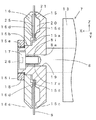
図5に示されるように、第1フランジ15において、保持部15cの端面(図では左端の面)から深い凹部20の内底面までの深さをL1、第1の凹部21の内底面までの深さをL2、回転刃9の背面からサポート部15dの端面(図では左端の面)までの距離をL3とする。第2フランジ16において、保持部16cの端面(図では右端の面)から第2の凹部25の内底面までの深さをL4、回転刃9の前面からサポート部16dの端面(図では右端の面)までの距離をL5とする。
As shown in FIG. 5, in the
一般に、スピンドルにおいて、回転刃が回転する際にフランジが受ける遠心力に起因するフランジの変位量は、フランジの外径、フランジの質量、回転刃の回転数などに依存する。第1フランジ15における深い凹部20の深さL1と第1の凹部21の深さL2と、第2フランジ16における第2の凹部25の深さL4とを最適化することによって、遠心力に起因する第1フランジ15の変位量と第2フランジ16の変位量とをほぼ等しくすることができる。例えば、本実施例においては、第1フランジ15の深い凹部20の深さL1を0.7〜1.5mm、第1フランジ15の第1の凹部21の深さL2を0.3〜0.5mm、第2フランジ16の第2の凹部25の深さL4を0.3〜0.5mmにすることによって、第1フランジ15の変位量と第2フランジ16の変位量とをほぼ等しくすることが可能になった。このことにより、回転刃9が高速回転した場合であっても、回転刃9のひずみや反りを抑えることができる。したがって、回転刃9が受ける遠心力に起因して発生する回転刃9の破損や蛇行を防止することができる。
Generally, in a spindle, the amount of displacement of the flange caused by the centrifugal force that the flange receives when the rotary blade rotates depends on the outer diameter of the flange, the mass of the flange, the rotational speed of the rotary blade, and the like. By optimizing the depth L1 of the
例えば、回転刃9に含まれる砥粒の粒径の最大値が15μmの場合を説明する。回転刃9の背面からサポート部15dの端面までの距離L3と回転刃9の前面からサポート部16dの端面までの距離L5とを、回転刃9に含まれる砥粒の粒径の最大値よりもわずかに大きくなるように0.02mmに設定した。このことによって、回転刃9が受ける遠心力に起因して回転刃9の変形(ひずみや撓みなど)が発生したとしても、その変形を抑制することができる。したがって、回転刃9が高速回転した場合であっても、回転刃9がひずみや撓みによって破損することを防止できる。
For example, the case where the maximum value of the grain size of the abrasive grains contained in the
各実施例においては、被切断物として、基板上に封止樹脂を形成した封止済基板2を切断する場合を示した。これに限らず、被切断物における基板として、ガラスエポキシ積層板、プリント配線板、セラミックス基板、金属ベース基板、フィルムベース基板などを使用し、その上に封止樹脂を形成した封止済基板についても本発明を適用できる。
In each Example, the case where the sealed board |
機能素子としては、IC(Integrated Circuit )、トランジスタ、ダイオードなどの半導体素子の他に、センサ、フィルタ、アクチュエータ、発振子などが含まれる。1個の領域に複数個の機能素子が搭載されてもよい。 The functional elements include sensors, filters, actuators, oscillators, etc., in addition to semiconductor elements such as IC (Integrated Circuit), transistors, and diodes. A plurality of functional elements may be mounted in one area.
更に、シリコン半導体や化合物半導体のウェーハがウェーハ状態のまま一括樹脂封止されたウェーハレベルパッケージのような実質的に円形の形状を有する被切断物を切断する場合においても、ここまで説明した内容を適用できる。 Furthermore, even when cutting a workpiece having a substantially circular shape, such as a wafer level package in which a silicon semiconductor or a compound semiconductor wafer is encapsulated with a resin in a wafer state, the contents described so far are used. Applicable.
被切断物は封止済基板2に限定されない。樹脂成形法によって製造した部材(樹脂成形体)を切断してレンズアレイなどの光学部品、一般的な樹脂成形品などの製品を製造する場合がある。この場合における樹脂成形体が被切断物に含まれる。回転刃を使用して被切断物を切断する際に、回転刃9における変形、振動などをできるだけ抑制したい場合、言い換えれば、切断されることによって製造される製品に要求される寸法精度、外観品位などのレベル高い場合ほど、本発明は有効である。
The object to be cut is not limited to the sealed
例えば、回転刃9を高速回転させる場合などにおいて、本発明によっても回転刃9に変形が発生することを充分に抑制することができない場合が考えられる。その原因として、第1フランジ15の外周部と第2フランジ16の外周部との少なくとも一方が外側に向かって(回転刃9の表面から離れる方向に向かって)曲がるように変形することが挙げられる。この場合には、変形している方のフランジが有する保持部(保持部15c又は16cのうち少なくとも一方)の端面を、回転刃9が停止している状態において、回転軸に近づくほど回転刃9から離れるように傾斜させてもよい。回転刃9の面に対する保持部15cの端面又は保持部16cの端面の角度を調整することによって、回転刃9の変形を抑制することができる。
For example, when the
本発明は、上述した各実施例に限定されるものではなく、本発明の趣旨を逸脱しない範囲内で、必要に応じて、任意にかつ適宜に組み合わせ、変更し、又は選択して採用できるものである。 The present invention is not limited to the above-described embodiments, and can be arbitrarily combined, modified, or selected and adopted as necessary within the scope not departing from the gist of the present invention. It is.
1 切断装置
2 封止済基板(被切断物)
3 基板供給機構
4 切断用テーブル(テーブル)
5 移動機構
6 回転機構
7 スピンドル(切断機構)
8 回転軸
8a 先端部
8i 雌ねじ部
9 回転刃
10 検査用テーブル
11 切断済基板
12 トレイ
13 スピンドル本体部
14 スピンドルモータ
15 第1フランジ(第1の固定部材)
15a ベース部
15b ベース部
15c 保持部(第1の保持部)
15d サポート部(第1のサポート部)
15e ナット雄ねじ部
16 第2フランジ(第2の固定部材)
16c 保持部(第2の保持部)
16d サポート部(第2のサポート部)
17 ボルト
17e 雄ねじ部
18 ナット
18i ナット雌ねじ部
19 貫通穴
20 深い凹部
21 第1の凹部
22 凹部
23 貫通孔
24 貫通穴
25 第2の凹部
26 六角穴
A 基板供給モジュール
B 基板切断モジュール
C 検査モジュール
CTL 制御部
P 製品
AG 砥粒
L1 深い凹部の深さ
L2 第1の凹部の深さ
L3 回転刃の背面からサポート部の端面までの距離(第1の距離)
L4 第2の凹部の深さ
L5 回転刃の前面からサポート部の端面までの距離(第2の距離)
DESCRIPTION OF
3
5 Moving
DESCRIPTION OF
15a base part 15b base part 15c holding part (first holding part)
15d Support section (first support section)
15e Nut
16c holding part (second holding part)
16d support section (second support section)
17 Bolt 17e Male thread part 18 Nut 18i Nut
L4 Depth of the second recess L5 Distance from the front surface of the rotary blade to the end surface of the support portion (second distance)
Claims (14)
前記切断機構に設けられた回転軸と、
前記回転軸に対して固定された円板状の回転刃と、
前記回転刃における前記切断機構の本体に近い側に位置する第1の面に部分的に密着する第1の固定部材と、
前記第1の固定部材の外周部に設けられ前記回転刃の前記第1の面に密着する第1の保持部と、
前記第1の固定部材に設けられた第1の凹部と、
前記回転刃の軸方向に沿って見て前記第1の凹部の少なくとも一部に重なるようにして前記第1の固定部材に設けられ、前記第1の凹部の深さよりも大きい深さを有する深い凹部と、
前記第1の固定部材に設けられた第1のサポート部と、
前記回転刃の第2の面に部分的に密着する第2の固定部材と、
前記第2の固定部材の外周部に設けられ前記回転刃の前記第2の面に密着する第2の保持部と、
前記第2の固定部材に設けられた第2の凹部と、
前記第2の固定部材に設けられた第2のサポート部とを備え、
前記第1の固定部材と前記第2の固定部材とによって前記回転刃が挟まれた状態において前記回転刃が前記回転軸に対して固定され、
前記回転刃を間に置いて前記第2の凹部が前記第1の凹部に相対向して配置され、
前記回転刃が回転することによって発生する遠心力に起因する前記回転刃の変形が抑制されることを特徴とする切断装置。 A table on which the workpiece is placed, a cutting mechanism for cutting the workpiece, and a moving mechanism for moving the table and the cutting mechanism relative to each other, by cutting the workpiece A cutting device used when manufacturing a plurality of products,
A rotating shaft provided in the cutting mechanism;
A disc-shaped rotary blade fixed to the rotary shaft;
A first fixing member that is partially in close contact with a first surface located on the side of the rotary blade close to the main body of the cutting mechanism;
A first holding portion provided on an outer peripheral portion of the first fixing member and in close contact with the first surface of the rotary blade;
A first recess provided in the first fixing member;
A deep portion that is provided in the first fixing member so as to overlap at least a part of the first recess when viewed along the axial direction of the rotary blade , and has a depth greater than the depth of the first recess. A recess,
A first support portion provided on the first fixing member;
A second fixing member that is partially in close contact with the second surface of the rotary blade;
A second holding portion that is provided on an outer peripheral portion of the second fixing member and is in close contact with the second surface of the rotary blade;
A second recess provided in the second fixing member;
A second support portion provided on the second fixing member,
The rotary blade is fixed to the rotary shaft in a state where the rotary blade is sandwiched between the first fixing member and the second fixing member;
The second recess is disposed opposite to the first recess with the rotary blade in between,
A cutting apparatus, wherein deformation of the rotary blade due to centrifugal force generated by rotation of the rotary blade is suppressed.
前記第1の保持部と前記第1の凹部と前記深い凹部と前記第1のサポート部とが円周状に形成され、前記第2の保持部と前記第2の凹部と前記第2のサポート部とが円周状に形成されることを特徴とする切断装置。 The cutting device according to claim 1, wherein
The first holding portion, the first concave portion, the deep concave portion, and the first support portion are formed in a circumferential shape, and the second holding portion, the second concave portion, and the second support are formed. A cutting device characterized in that the portion is formed in a circumferential shape.
前記深い凹部の深さは前記第1の凹部の深さ及び前記第2の凹部の深さよりも大きいことを特徴とする切断装置。 The cutting device according to claim 1, wherein
The depth of the said deep recessed part is larger than the depth of the said 1st recessed part, and the depth of the said 2nd recessed part, The cutting device characterized by the above-mentioned.
前記第1のサポート部は前記第1の固定部材における前記回転軸に近い側に設けられ、
前記第2のサポート部は前記第2の固定部材における前記回転軸に近い側に設けられ、
前記回転刃を間に置いて前記第1のサポート部と前記第2のサポート部とが相対向して配置され、
前記回転刃の前記第1の面から前記第1のサポート部の端面までの第1の距離と前記回転刃の前記第2の面から前記第2のサポート部の端面までの第2の距離とが等しい所定の距離であり、
前記所定の距離は前記回転刃が有する砥粒の最大径よりも大きく、前記回転刃の変形が許容される範囲における変形量の最大値よりも小さいことを特徴とする切断装置。 The cutting device according to claim 1, wherein
The first support portion is provided on a side of the first fixing member close to the rotation shaft,
The second support portion is provided on a side of the second fixing member close to the rotation shaft,
The first support part and the second support part are arranged to face each other with the rotary blade in between,
A first distance from the first surface of the rotary blade to an end surface of the first support portion, and a second distance from the second surface of the rotary blade to an end surface of the second support portion; Are equal predetermined distances,
The cutting apparatus according to claim 1, wherein the predetermined distance is larger than a maximum diameter of abrasive grains of the rotary blade and smaller than a maximum deformation amount in a range in which the rotary blade is allowed to be deformed.
前記深い凹部は、前記第1の固定部材において、前記回転刃の前記第1の面に相対向する面又は前記相対向する面の反対面のうち少なくとも一方において設けられることを特徴とする切断装置。 The cutting device according to claim 1, wherein
The deep recess is provided on at least one of a surface facing the first surface of the rotary blade or a surface opposite to the facing surface in the first fixing member. .
前記被切断物は封止済基板であることを特徴とする切断装置。 In the cutting device as described in any one of Claims 1-5,
The cutting apparatus, wherein the object to be cut is a sealed substrate.
前記被切断物は、前記複数の製品にそれぞれ対応する複数の領域においてそれぞれ機能素子が作りこまれた基板であることを特徴とする切断装置。 In the cutting device as described in any one of Claims 1-5,
The cutting apparatus is a cutting device in which a functional element is formed in each of a plurality of regions corresponding to the plurality of products.
第1の保持部と、第1の凹部と、前記回転刃の軸方向に沿って見て前記第1の凹部に重なるようにして設けられ前記第1の凹部の深さよりも大きい深さを有する深い凹部と、第1のサポート部とを有する第1の固定部材を準備する工程と、
第2の保持部と、第2の凹部と、第2のサポート部とを有する第2の固定部材を準備する工程と、
前記第1の固定部材と前記第2の固定部材とによって挟まれた状態において前記回転軸に固定された前記回転刃を準備する工程と、
切断機構を使用して前記回転刃を回転させる工程とを備え、
準備された前記第1の固定部材において前記第1の保持部が外周部に設けられ、
準備された前記第2の固定部材において前記第2の保持部が外周部に設けられ、
前記回転刃を準備する工程では、前記第2の凹部を前記第1の凹部に相対向して配置し、前記回転刃における前記切断機構の本体に近い側に位置する第1の面に前記第1の保持部を密着させ、前記回転刃の第2の面に前記第2の保持部を密着させ、
前記回転刃を回転させる工程では、前記回転刃が回転することによって発生する遠心力に起因する前記回転刃の変形を抑制することを特徴とする切断方法。 A step of placing the object to be cut on a table, and a step of relatively moving the disk-shaped rotary blade fixed to the rotating shaft and the object to be cut, by cutting the object to be cut A cutting method for producing a plurality of products,
A first holding portion, a first recess, and a depth greater than the depth of the first recess provided to overlap the first recess when viewed along the axial direction of the rotary blade. Preparing a first fixing member having a deep recess and a first support portion;
Preparing a second fixing member having a second holding portion, a second recess, and a second support portion;
Preparing the rotary blade fixed to the rotary shaft in a state sandwiched between the first fixed member and the second fixed member;
And rotating the rotary blade using a cutting mechanism ,
In the prepared first fixing member, the first holding portion is provided on an outer peripheral portion,
In the prepared second fixing member, the second holding portion is provided on the outer peripheral portion,
In the step of preparing the rotary blade, the second concave portion is disposed opposite to the first concave portion, and the first surface located on a side of the rotary blade close to the main body of the cutting mechanism is disposed on the first surface. 1 holding part is brought into close contact, and the second holding part is brought into close contact with the second surface of the rotary blade,
In the step of rotating the rotary blade, the cutting method is characterized by suppressing deformation of the rotary blade due to centrifugal force generated by the rotation of the rotary blade.
準備された前記第1の固定部材において、前記第1の保持部と、前記第1の凹部と、前記深い凹部と、前記第1のサポート部とが円周状に形成され、
準備された前記第2の固定部材において、前記第2の保持部と、前記第2の凹部と、前記第2のサポート部とが円周状に形成されることを特徴とする切断方法。 The cutting method according to claim 8, wherein
In the prepared first fixing member, the first holding portion, the first concave portion, the deep concave portion, and the first support portion are formed in a circumferential shape,
In the prepared second fixing member, the second holding portion, the second concave portion, and the second support portion are formed in a circumferential shape.
それぞれ準備された前記第1の固定部材と前記第2の固定部材とにおいて、前記深い凹部の深さは前記第1の凹部の深さ及び前記第2の凹部の深さよりも大きいことを特徴とする切断方法。 The cutting method according to claim 8, wherein
In the first fixing member and the second fixing member respectively prepared, the depth of the deep recess is greater than the depth of the first recess and the depth of the second recess. How to cut.
それぞれ準備された前記第1の固定部材と前記第2の固定部材とにおいて、
前記第1のサポート部は前記第1の固定部材における前記回転軸に近い側に設けられ、
前記第2のサポート部は前記第2の固定部材における前記回転軸に近い側に設けられ、
前記回転刃を間に置いて前記第1のサポート部と前記第2のサポート部とが相対向して配置され、
前記回転刃の前記第1の面から前記第1のサポート部の端面までの第1の距離と前記回転刃の前記第2の面から前記第2のサポート部の端面までの第2の距離とが等しい所定の距離であり、
前記所定の距離は前記回転刃が有する砥粒の最大径よりも大きく、前記回転刃の変形が許容される範囲における変形量の最大値よりも小さいことを特徴とする切断方法。 The cutting method according to claim 8, wherein
In the first fixing member and the second fixing member respectively prepared,
The first support portion is provided on a side of the first fixing member close to the rotation shaft,
The second support portion is provided on a side of the second fixing member close to the rotation shaft,
The first support part and the second support part are arranged to face each other with the rotary blade in between,
A first distance from the first surface of the rotary blade to an end surface of the first support portion, and a second distance from the second surface of the rotary blade to an end surface of the second support portion; Are equal predetermined distances,
The cutting method according to claim 1, wherein the predetermined distance is larger than a maximum diameter of the abrasive grains of the rotary blade and smaller than a maximum deformation amount in a range in which the rotary blade is allowed to be deformed.
準備された前記第1の固定部材において、前記深い凹部は、前記回転刃の前記第1の面に相対向する面又は前記相対向する面の反対面のうち少なくとも一方において設けられることを特徴とする切断方法。 The cutting method according to claim 8, wherein
In the prepared first fixing member, the deep recess is provided on at least one of a surface facing the first surface of the rotary blade or a surface opposite to the facing surface. How to cut.
前記被切断物は封止済基板であることを特徴とする切断方法。 In the cutting method as described in any one of Claims 8-12,
The cutting method, wherein the object to be cut is a sealed substrate.
前記被切断物は、前記複数の製品にそれぞれ対応する複数の領域においてそれぞれ機能素子が作りこまれた基板であることを特徴とする切断方法。 In the cutting method as described in any one of Claims 8-12,
The cutting method is a substrate in which functional elements are formed in a plurality of regions corresponding to the plurality of products, respectively.
Priority Applications (4)
| Application Number | Priority Date | Filing Date | Title |
|---|---|---|---|
| JP2015098196A JP6430329B2 (en) | 2015-05-13 | 2015-05-13 | Cutting apparatus and cutting method |
| TW105111452A TWI599442B (en) | 2015-05-13 | 2016-04-13 | Cutting device and cutting method |
| KR1020160056996A KR101821882B1 (en) | 2015-05-13 | 2016-05-10 | Cutting device and cutting method |
| CN201610317620.7A CN106142198B (en) | 2015-05-13 | 2016-05-12 | Shearing device and cutting-off method |
Applications Claiming Priority (1)
| Application Number | Priority Date | Filing Date | Title |
|---|---|---|---|
| JP2015098196A JP6430329B2 (en) | 2015-05-13 | 2015-05-13 | Cutting apparatus and cutting method |
Publications (3)
| Publication Number | Publication Date |
|---|---|
| JP2016209980A JP2016209980A (en) | 2016-12-15 |
| JP2016209980A5 JP2016209980A5 (en) | 2017-11-24 |
| JP6430329B2 true JP6430329B2 (en) | 2018-11-28 |
Family
ID=57352811
Family Applications (1)
| Application Number | Title | Priority Date | Filing Date |
|---|---|---|---|
| JP2015098196A Active JP6430329B2 (en) | 2015-05-13 | 2015-05-13 | Cutting apparatus and cutting method |
Country Status (4)
| Country | Link |
|---|---|
| JP (1) | JP6430329B2 (en) |
| KR (1) | KR101821882B1 (en) |
| CN (1) | CN106142198B (en) |
| TW (1) | TWI599442B (en) |
Families Citing this family (6)
| Publication number | Priority date | Publication date | Assignee | Title |
|---|---|---|---|---|
| KR102303151B1 (en) | 2017-03-31 | 2021-09-23 | 생-고뱅 어브레이시브즈, 인코포레이티드 | grinding wheel assembly |
| JP6560714B2 (en) * | 2017-06-26 | 2019-08-14 | Towa株式会社 | Blade replacement mechanism, cutting device, and blade replacement method |
| JP7138452B2 (en) * | 2018-03-01 | 2022-09-16 | 株式会社ディスコ | Flange mechanism |
| WO2020081906A1 (en) | 2018-10-19 | 2020-04-23 | Saint-Gobain Abrasives, Inc. | Grinding wheel assembly |
| JP7098581B2 (en) * | 2019-07-29 | 2022-07-11 | Towa株式会社 | Blade replacement mechanism, cutting device, and manufacturing method of cut products |
| US11730575B2 (en) * | 2020-09-10 | 2023-08-22 | James R. Glidewell Dental Ceramics, Inc. | Milling burs and systems and methods for performing quality control of the same |
Family Cites Families (18)
| Publication number | Priority date | Publication date | Assignee | Title |
|---|---|---|---|---|
| US5494698A (en) * | 1994-11-07 | 1996-02-27 | Xerox Corporation | Teflon filled resinoid dicing blades for fabricating silicon die modules |
| US5992285A (en) * | 1994-11-21 | 1999-11-30 | Talarico; Joe | Floating punch holder |
| US5701789A (en) * | 1995-04-10 | 1997-12-30 | Best Cutting Die Company | Waste repellent die structure |
| US5827159A (en) * | 1996-05-15 | 1998-10-27 | Adachi; Hiroshi | Combination tool changer and storage device for die cutter |
| US5896796A (en) * | 1997-06-06 | 1999-04-27 | Chih; Chen-Keng | Device for punching holes in a bicycle rim |
| AU684703B3 (en) * | 1997-08-19 | 1997-12-18 | Fu-Chuan Huang | Cutting mechanism for a thermal-shrinking film labeling machine |
| JP4023525B2 (en) * | 1997-09-04 | 2007-12-19 | 株式会社ディスコ | Electroformed blade |
| DE19857913C2 (en) * | 1998-12-16 | 2003-10-02 | System 3R Internat Ab Vaelling | coupling device |
| JP3061113U (en) * | 1999-01-29 | 1999-09-17 | 榮昌 陳 | Die-cutting device with cutting edge protection device |
| EP1044819A3 (en) * | 1999-04-14 | 2001-06-27 | Star Micronics Co., Ltd. | Cutter apparatus and printer |
| CH693824A5 (en) * | 1999-04-28 | 2004-02-27 | Bobst Sa | Device for fixing and guiding a bearing on a frame. |
| CN1226116C (en) * | 1999-05-31 | 2005-11-09 | 比特林制造传播有限公司 | Cutting machine |
| JP4559094B2 (en) * | 2004-02-16 | 2010-10-06 | 株式会社ディスコ | Cutting blade mounting device, cutting device |
| JP4904606B2 (en) * | 2006-08-03 | 2012-03-28 | 株式会社東京精密 | Cutting blade mounting device and cutting blade mounting method thereof |
| JP2008103648A (en) * | 2006-10-23 | 2008-05-01 | Matsushita Electric Ind Co Ltd | Apparatus for manufacturing semiconductor device, and method for manufacturing the semiconductor device |
| JP5096052B2 (en) * | 2007-06-22 | 2012-12-12 | 株式会社ディスコ | Cutting equipment |
| JP5226394B2 (en) * | 2008-06-16 | 2013-07-03 | 株式会社ディスコ | Flange end face correction method |
| JP2015085466A (en) * | 2013-10-31 | 2015-05-07 | 株式会社ディスコ | Flange mechanism |
-
2015
- 2015-05-13 JP JP2015098196A patent/JP6430329B2/en active Active
-
2016
- 2016-04-13 TW TW105111452A patent/TWI599442B/en active
- 2016-05-10 KR KR1020160056996A patent/KR101821882B1/en active IP Right Grant
- 2016-05-12 CN CN201610317620.7A patent/CN106142198B/en active Active
Also Published As
| Publication number | Publication date |
|---|---|
| CN106142198B (en) | 2018-04-10 |
| KR20160134509A (en) | 2016-11-23 |
| JP2016209980A (en) | 2016-12-15 |
| CN106142198A (en) | 2016-11-23 |
| KR101821882B1 (en) | 2018-01-24 |
| TW201710022A (en) | 2017-03-16 |
| TWI599442B (en) | 2017-09-21 |
Similar Documents
| Publication | Publication Date | Title |
|---|---|---|
| JP6430329B2 (en) | Cutting apparatus and cutting method | |
| TWI599450B (en) | Cutting device and cutting method | |
| KR101905199B1 (en) | Processing method of device wafer with bump | |
| JP6305212B2 (en) | Grinding apparatus and rectangular substrate grinding method | |
| TW201632308A (en) | Mount flange | |
| JP2000357672A (en) | Dicing saw laminated blade | |
| KR102644406B1 (en) | Machining apparatus | |
| JP5268599B2 (en) | Grinding apparatus and grinding method | |
| JP5938296B2 (en) | Grinding equipment | |
| JP2015223667A (en) | Griding device and grinding method for rectangular substrate | |
| JP6678468B2 (en) | Nozzle adjustment jig | |
| US11376707B2 (en) | Grinding method | |
| TW201706077A (en) | Cutting blade and installation structure for the cutting blade capable of machining an inner diameter with a high accuracy and extending the lifetime of a blade mount | |
| JP2007227594A (en) | Cutting jig, and method for cutting optical substrate wafer | |
| TWI747296B (en) | Flange end face correction device, cutting device, flange end face correction method, and cut product manufacturing method | |
| TWI827831B (en) | With abutment blade | |
| JP7446667B2 (en) | Cutting blade, how to attach the cutting blade, and how to process the workpiece | |
| JP7300912B2 (en) | processing equipment | |
| JP6797043B2 (en) | Chuck table of processing equipment | |
| US20220375742A1 (en) | Processing method of wafer | |
| JP7383333B2 (en) | blade with base | |
| JP5635807B2 (en) | Cutting device | |
| JP6440560B2 (en) | Correction device | |
| JP2022139927A (en) | Semiconductor manufacturing device and method for manufacturing semiconductor device | |
| JP2018148182A (en) | Blade retainer and dicing device |
Legal Events
| Date | Code | Title | Description |
|---|---|---|---|
| A521 | Request for written amendment filed |
Free format text: JAPANESE INTERMEDIATE CODE: A523 Effective date: 20171011 |
|
| A621 | Written request for application examination |
Free format text: JAPANESE INTERMEDIATE CODE: A621 Effective date: 20180130 |
|
| TRDD | Decision of grant or rejection written | ||
| A01 | Written decision to grant a patent or to grant a registration (utility model) |
Free format text: JAPANESE INTERMEDIATE CODE: A01 Effective date: 20181002 |
|
| A977 | Report on retrieval |
Free format text: JAPANESE INTERMEDIATE CODE: A971007 Effective date: 20180928 |
|
| A61 | First payment of annual fees (during grant procedure) |
Free format text: JAPANESE INTERMEDIATE CODE: A61 Effective date: 20181031 |
|
| R150 | Certificate of patent or registration of utility model |
Ref document number: 6430329 Country of ref document: JP Free format text: JAPANESE INTERMEDIATE CODE: R150 |
|
| R250 | Receipt of annual fees |
Free format text: JAPANESE INTERMEDIATE CODE: R250 |
|
| R250 | Receipt of annual fees |
Free format text: JAPANESE INTERMEDIATE CODE: R250 |
|
| R250 | Receipt of annual fees |
Free format text: JAPANESE INTERMEDIATE CODE: R250 |