JP6252425B2 - 電子部品 - Google Patents
電子部品 Download PDFInfo
- Publication number
- JP6252425B2 JP6252425B2 JP2014205136A JP2014205136A JP6252425B2 JP 6252425 B2 JP6252425 B2 JP 6252425B2 JP 2014205136 A JP2014205136 A JP 2014205136A JP 2014205136 A JP2014205136 A JP 2014205136A JP 6252425 B2 JP6252425 B2 JP 6252425B2
- Authority
- JP
- Japan
- Prior art keywords
- end surface
- electronic component
- external electrode
- circuit element
- ground external
- Prior art date
- Legal status (The legal status is an assumption and is not a legal conclusion. Google has not performed a legal analysis and makes no representation as to the accuracy of the status listed.)
- Active
Links
- 239000000758 substrate Substances 0.000 claims description 22
- 239000006247 magnetic powder Substances 0.000 claims description 4
- 239000002184 metal Substances 0.000 claims description 4
- 229910052751 metal Inorganic materials 0.000 claims description 4
- 239000004020 conductor Substances 0.000 description 23
- 239000000463 material Substances 0.000 description 20
- 238000004519 manufacturing process Methods 0.000 description 15
- 238000010586 diagram Methods 0.000 description 10
- 239000002245 particle Substances 0.000 description 10
- 238000000605 extraction Methods 0.000 description 7
- 239000000696 magnetic material Substances 0.000 description 5
- 238000000034 method Methods 0.000 description 5
- 239000004065 semiconductor Substances 0.000 description 5
- 239000011248 coating agent Substances 0.000 description 4
- 238000000576 coating method Methods 0.000 description 4
- 230000005611 electricity Effects 0.000 description 4
- 229910000679 solder Inorganic materials 0.000 description 4
- 230000003068 static effect Effects 0.000 description 4
- 229910052802 copper Inorganic materials 0.000 description 3
- 229910052763 palladium Inorganic materials 0.000 description 3
- 229910052709 silver Inorganic materials 0.000 description 3
- 238000005336 cracking Methods 0.000 description 2
- 230000000694 effects Effects 0.000 description 2
- 230000005484 gravity Effects 0.000 description 2
- PNEYBMLMFCGWSK-UHFFFAOYSA-N aluminium oxide Inorganic materials [O-2].[O-2].[O-2].[Al+3].[Al+3] PNEYBMLMFCGWSK-UHFFFAOYSA-N 0.000 description 1
- 238000005520 cutting process Methods 0.000 description 1
- 230000003247 decreasing effect Effects 0.000 description 1
- 239000006185 dispersion Substances 0.000 description 1
- 239000011521 glass Substances 0.000 description 1
- 239000002241 glass-ceramic Substances 0.000 description 1
- 229910010272 inorganic material Inorganic materials 0.000 description 1
- 239000011147 inorganic material Substances 0.000 description 1
- 238000009413 insulation Methods 0.000 description 1
- 238000003475 lamination Methods 0.000 description 1
- 239000002923 metal particle Substances 0.000 description 1
- 229910052759 nickel Inorganic materials 0.000 description 1
- 230000002265 prevention Effects 0.000 description 1
- 239000011347 resin Substances 0.000 description 1
- 229920005989 resin Polymers 0.000 description 1
- 229910000859 α-Fe Inorganic materials 0.000 description 1
Images
Classifications
-
- H—ELECTRICITY
- H01—ELECTRIC ELEMENTS
- H01F—MAGNETS; INDUCTANCES; TRANSFORMERS; SELECTION OF MATERIALS FOR THEIR MAGNETIC PROPERTIES
- H01F27/00—Details of transformers or inductances, in general
- H01F27/40—Structural association with built-in electric component, e.g. fuse
- H01F27/402—Association of measuring or protective means
-
- H—ELECTRICITY
- H01—ELECTRIC ELEMENTS
- H01F—MAGNETS; INDUCTANCES; TRANSFORMERS; SELECTION OF MATERIALS FOR THEIR MAGNETIC PROPERTIES
- H01F17/00—Fixed inductances of the signal type
- H01F17/0006—Printed inductances
- H01F17/0013—Printed inductances with stacked layers
-
- H—ELECTRICITY
- H05—ELECTRIC TECHNIQUES NOT OTHERWISE PROVIDED FOR
- H05F—STATIC ELECTRICITY; NATURALLY-OCCURRING ELECTRICITY
- H05F3/00—Carrying-off electrostatic charges
- H05F3/02—Carrying-off electrostatic charges by means of earthing connections
-
- H—ELECTRICITY
- H01—ELECTRIC ELEMENTS
- H01F—MAGNETS; INDUCTANCES; TRANSFORMERS; SELECTION OF MATERIALS FOR THEIR MAGNETIC PROPERTIES
- H01F17/00—Fixed inductances of the signal type
- H01F17/0006—Printed inductances
- H01F2017/0066—Printed inductances with a magnetic layer
-
- H—ELECTRICITY
- H01—ELECTRIC ELEMENTS
- H01F—MAGNETS; INDUCTANCES; TRANSFORMERS; SELECTION OF MATERIALS FOR THEIR MAGNETIC PROPERTIES
- H01F17/00—Fixed inductances of the signal type
- H01F2017/0093—Common mode choke coil
-
- H—ELECTRICITY
- H10—SEMICONDUCTOR DEVICES; ELECTRIC SOLID-STATE DEVICES NOT OTHERWISE PROVIDED FOR
- H10D—INORGANIC ELECTRIC SEMICONDUCTOR DEVICES
- H10D89/00—Aspects of integrated devices not covered by groups H10D84/00 - H10D88/00
- H10D89/60—Integrated devices comprising arrangements for electrical or thermal protection, e.g. protection circuits against electrostatic discharge [ESD]
Landscapes
- Engineering & Computer Science (AREA)
- Power Engineering (AREA)
- Microelectronics & Electronic Packaging (AREA)
- Coils Or Transformers For Communication (AREA)
- Manufacturing Cores, Coils, And Magnets (AREA)
- Filters And Equalizers (AREA)
Description
積層された複数の絶縁層を含む積層体と、
前記積層体内に設けられている回路素子と、
前記積層体内に設けられている静電気放電素子と、
前記静電気放電素子と前記回路素子とを電気的に接続する回路素子用外部電極と、
前記静電気放電素子に接続され、前記静電気放電素子をグランドに電気的に接続するためのグランド用外部電極と
を備え、
前記積層体は、前記絶縁層の積層方向に位置すると共に互いに反対側に位置する第1端面と第2端面とを有し、
前記静電気放電素子は、前記回路素子よりも、前記積層体の前記第1端面側に配置され、
前記グランド用外部電極の前記回路素子側の端部の前記第1端面からの高さは、前記回路素子の前記グランド用外部電極側の端部の前記第1端面からの高さよりも、低いことを特徴としている。
前記積層体の前記側面には、前記第1端面から切り欠かれると共に前記第1端面から前記第2端面に向かって延在する凹部を有し、
前記グランド用外部電極は、前記積層体の前記凹部に嵌め込まれている。
前記グランド用外部電極における前記積層体の前記凹部の内面に接触する接触部分の形状は、前記第1端面から前記第2端面に向かって延在する階段状であり、
前記積層体の前記凹部の内面における前記グランド用外部電極に接触する接触部分の形状は、前記第1端面から前記第2端面に向かって延在する階段状であり、
前記グランド用外部電極の前記接触部分と前記積層体の前記接触部分とは、互いに、係合する。
前記積層体の前記第1端面には、前記第1端面に開口を有すると共に前記第1端面から前記第2端面に向かって延在する孔部を有し、
前記グランド用外部電極は、前記積層体の前記孔部に嵌め込まれている。
前記グランド用外部電極における前記積層体の前記孔部の内面に接触する接触部分の形状は、前記第1端面から前記第2端面に向かって延在する階段状であり、
前記積層体の前記孔部の内面における前記グランド用外部電極に接触する接触部分の形状は、前記第1端面から前記第2端面に向かって延在する階段状であり、
前記グランド用外部電極の前記接触部分と前記積層体の前記接触部分とは、互いに、係合する。
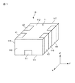
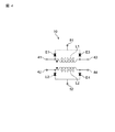
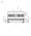
図1は、本発明の第1実施形態の電子部品を示す斜視図である。図2は、電子部品の断面図である。図3は、電子部品の分解斜視図である。図1と図2と図3に示すように、電子部品10は、積層体1と、積層体1内に設けられている回路素子2と、積層体1内に設けられている静電気放電素子3と、静電気放電素子3と回路素子2とを電気的に接続する第1〜第4回路素子用外部電極41〜44と、静電気放電素子3に接続され、静電気放電素子3をグランドに電気的に接続するための第1、第2グランド用外部電極51,52とを有する。
図6は、本発明の第2実施形態の電子部品を示す簡略構成図である。第2実施形態は、前記第1実施形態とは、静電気放電素子と回路素子との間の距離、および、静電気放電素子と積層体の第1端面との間の距離が相違する。この相違する構成のみを以下に説明する。なお、第2実施形態において、第1実施形態と同一の符号は、第1実施形態と同じ構成であるため、その説明を省略する。
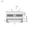
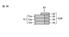
図8は、本発明の第3実施形態の電子部品を示す簡略構成図である。第3実施形態は、前記第1実施形態とは、グランド用外部電極の形状が相違する。この相違する構成のみを以下に説明する。なお、第3実施形態において、第1実施形態と同一の符号は、第1実施形態と同じ構成であるため、その説明を省略する。
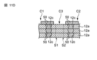
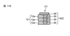
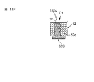
図10は、本発明の第4実施形態の電子部品を示す簡略構成図である。第4実施形態は、前記第1実施形態とは、グランド用外部電極の形状が相違する。この相違する構成のみを以下に説明する。なお、第4実施形態において、第1実施形態と同一の符号は、第1実施形態と同じ構成であるため、その説明を省略する。
1b,1c,2b,2c 接触部分
2 回路素子
3 静電気放電素子
6 実装基板
10,10A,10B,10C 電子部品
11 非磁性体(絶縁層)
12 磁性体(絶縁層)
111 第1端面
112 第2端面
115〜118 第1〜第4側面
21〜24 第1〜第4コイル
31〜35 第1〜第5放電電極
41〜44 第1〜第4回路素子用外部電極
51,51B,51C 第1グランド用外部電極
52,52B,52C 第2グランド用外部電極
51b,51c,52b,52c 接触部分
11b,12b,121b,122b 凹部
131c,132c 孔部
H1 グランド用外部電極の積層体の第1端面からの高さ
H2 回路素子の積層体の第1端面からの高さ
L1 静電気放電素子と回路素子との間の距離
L2 静電気放電素子と積層体の第1端面との間の距離
Claims (11)
- 積層された複数の絶縁層を含む積層体と、
前記積層体内に設けられている回路素子と、
前記積層体内に設けられている静電気放電素子と、
前記静電気放電素子と前記回路素子とを電気的に接続する回路素子用外部電極と、
前記静電気放電素子に接続され、前記静電気放電素子をグランドに電気的に接続するためのグランド用外部電極と
を備え、
前記積層体は、前記絶縁層の積層方向に位置すると共に互いに反対側に位置する第1端面と第2端面とを有し、
前記静電気放電素子は、前記回路素子よりも、前記積層体の前記第1端面側に配置され、
前記回路素子用外部電極は、前記積層体の前記第1端面と前記第2端面との間の側面と、前記側面から折り返されて前記第1端面と、前記側面から折り返されて前記第2端面とに設けられ、
前記グランド用外部電極は、前記積層体の前記第1端面から、前記積層体の前記第1端面と前記第2端面との間の側面に渡って、設けられ、
前記グランド用外部電極の前記回路素子側の端部の前記第1端面からの高さは、前記回路素子の前記グランド用外部電極側の端部の前記第1端面からの高さよりも、低いことを特徴とする電子部品。 - 請求項1に記載の電子部品において、
前記絶縁層は、非磁性体と磁性体とを含み、前記回路素子と前記静電気放電素子は、それぞれ、前記非磁性体に覆われ、前記回路素子を覆う前記非磁性体と前記静電気放電素子を覆う前記非磁性体との間には、前記磁性体が配置されることを特徴とする電子部品。 - 請求項1または2に記載の電子部品において、
前記積層体の前記第1端面は、実装基板に実装される被実装面であることを特徴とする電子部品。 - 請求項3に記載の電子部品において、
前記積層体の前記側面には、前記第1端面から切り欠かれると共に前記第1端面から前記第2端面に向かって延在する凹部を有し、
前記グランド用外部電極は、前記積層体の前記凹部に嵌め込まれていることを特徴とする電子部品。 - 請求項4に記載の電子部品において、
前記グランド用外部電極における前記積層体の前記凹部の内面に接触する接触部分の形状は、前記第1端面から前記第2端面に向かって延在する階段状であり、
前記積層体の前記凹部の内面における前記グランド用外部電極に接触する接触部分の形状は、前記第1端面から前記第2端面に向かって延在する階段状であり、
前記グランド用外部電極の前記接触部分と前記積層体の前記接触部分とは、互いに、係合することを特徴とする電子部品。 - 請求項1または2に記載の電子部品において、
前記積層体の前記第1端面には、前記第1端面に開口を有すると共に前記第1端面から前記第2端面に向かって延在する孔部を有し、
前記グランド用外部電極は、前記積層体の前記孔部に嵌め込まれていることを特徴とする電子部品。 - 請求項6に記載の電子部品において、
前記グランド用外部電極における前記積層体の前記孔部の内面に接触する接触部分の形状は、前記第1端面から前記第2端面に向かって延在する階段状であり、
前記積層体の前記孔部の内面における前記グランド用外部電極に接触する接触部分の形状は、前記第1端面から前記第2端面に向かって延在する階段状であり、
前記グランド用外部電極の前記接触部分と前記積層体の前記接触部分とは、互いに、係合することを特徴とする電子部品。 - 請求項1から7の何れか一つに記載の電子部品において、
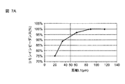
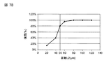
前記静電気放電素子と前記回路素子との間の距離は、50μm以上であることを特徴とする電子部品。 - 請求項1から8の何れか一つに記載の電子部品において、
前記静電気放電素子と前記積層体の前記第1端面との間の距離は、50μm以上であることを特徴とする電子部品。 - 請求項1から9の何れか一つに記載の電子部品において、
前記絶縁層は、金属磁性粉を含むことを特徴とする電子部品。 - 請求項1から10の何れか一つに記載の電子部品において、
前記静電気放電素子と前記回路素子との間の距離は、50μm以上で120μm以下であることを特徴とする電子部品。
Priority Applications (4)
| Application Number | Priority Date | Filing Date | Title |
|---|---|---|---|
| JP2014205136A JP6252425B2 (ja) | 2014-10-03 | 2014-10-03 | 電子部品 |
| KR1020150132535A KR101667888B1 (ko) | 2014-10-03 | 2015-09-18 | 전자 부품 |
| CN201510633047.6A CN105489341A (zh) | 2014-10-03 | 2015-09-29 | 电子部件 |
| US14/872,823 US20160099102A1 (en) | 2014-10-03 | 2015-10-01 | Electronic component |
Applications Claiming Priority (1)
| Application Number | Priority Date | Filing Date | Title |
|---|---|---|---|
| JP2014205136A JP6252425B2 (ja) | 2014-10-03 | 2014-10-03 | 電子部品 |
Publications (2)
| Publication Number | Publication Date |
|---|---|
| JP2016076556A JP2016076556A (ja) | 2016-05-12 |
| JP6252425B2 true JP6252425B2 (ja) | 2017-12-27 |
Family
ID=55633270
Family Applications (1)
| Application Number | Title | Priority Date | Filing Date |
|---|---|---|---|
| JP2014205136A Active JP6252425B2 (ja) | 2014-10-03 | 2014-10-03 | 電子部品 |
Country Status (4)
| Country | Link |
|---|---|
| US (1) | US20160099102A1 (ja) |
| JP (1) | JP6252425B2 (ja) |
| KR (1) | KR101667888B1 (ja) |
| CN (1) | CN105489341A (ja) |
Families Citing this family (13)
| Publication number | Priority date | Publication date | Assignee | Title |
|---|---|---|---|---|
| KR101630083B1 (ko) * | 2014-12-03 | 2016-06-13 | 삼성전기주식회사 | 코일 부품 |
| KR20170109782A (ko) * | 2016-03-22 | 2017-10-10 | 삼성전기주식회사 | 복합 전자 부품 |
| US10529661B2 (en) * | 2016-05-05 | 2020-01-07 | Cyntec Co., Ltd | Multilayer inductor and the fabrication method thereof |
| JP6696483B2 (ja) * | 2017-07-10 | 2020-05-20 | 株式会社村田製作所 | コイル部品 |
| US11424070B2 (en) * | 2018-06-19 | 2022-08-23 | Tdk Corporation | Coil component |
| JP6981389B2 (ja) | 2018-10-05 | 2021-12-15 | 株式会社村田製作所 | Dc−dcコンバータ用積層型コイルアレイおよびdc−dcコンバータ |
| JP2020061410A (ja) * | 2018-10-05 | 2020-04-16 | 株式会社村田製作所 | 積層型電子部品 |
| JP6977694B2 (ja) * | 2018-10-05 | 2021-12-08 | 株式会社村田製作所 | 積層型コイルアレイ |
| JP6919641B2 (ja) | 2018-10-05 | 2021-08-18 | 株式会社村田製作所 | 積層型電子部品 |
| KR102662845B1 (ko) * | 2018-11-22 | 2024-05-03 | 삼성전기주식회사 | 인덕터 |
| CN216435575U (zh) * | 2019-12-25 | 2022-05-03 | 株式会社村田制作所 | 多端子片式电感器 |
| JP7590904B2 (ja) * | 2021-03-31 | 2024-11-27 | Tdk株式会社 | 積層電子部品 |
| JP2023034657A (ja) * | 2021-08-31 | 2023-03-13 | Tdk株式会社 | 電子部品 |
Family Cites Families (26)
| Publication number | Priority date | Publication date | Assignee | Title |
|---|---|---|---|---|
| US5610565A (en) * | 1994-02-02 | 1997-03-11 | Murata Manufacturing Co., Ltd. | Composite LC device with a ground electrode not formed on the inductor parts |
| JP2002270429A (ja) * | 2001-03-14 | 2002-09-20 | Matsushita Electric Ind Co Ltd | インダクタ部品 |
| EP1367611A4 (en) * | 2001-03-08 | 2010-01-13 | Panasonic Corp | INDUCTIVE COMPONENT AND METHOD FOR THE PRODUCTION THEREOF |
| US7260890B2 (en) * | 2002-06-26 | 2007-08-28 | Georgia Tech Research Corporation | Methods for fabricating three-dimensional all organic interconnect structures |
| JP3900104B2 (ja) * | 2003-04-10 | 2007-04-04 | 松下電器産業株式会社 | 静電気対策部品 |
| KR100668977B1 (ko) * | 2005-06-27 | 2007-01-16 | 삼성전자주식회사 | 써지전압 보호용 소자 |
| CN101258565B (zh) * | 2005-09-07 | 2011-07-27 | 松下电器产业株式会社 | 复合电子元件 |
| JP4725343B2 (ja) | 2006-02-07 | 2011-07-13 | パナソニック株式会社 | 複合電子部品およびその製造方法 |
| US8493704B2 (en) * | 2007-04-11 | 2013-07-23 | Innochips Technology Co., Ltd. | Circuit protection device and method of manufacturing the same |
| KR100845948B1 (ko) * | 2007-04-11 | 2008-07-11 | 주식회사 이노칩테크놀로지 | 회로 보호 소자 및 그 제조 방법 |
| JP2010028695A (ja) | 2008-07-24 | 2010-02-04 | Murata Mfg Co Ltd | ノイズフィルタ部品及びコイル部品 |
| US8422190B2 (en) * | 2008-09-30 | 2013-04-16 | Tdk Corporation | Composite electronic device, manufacturing method thereof, and connection structure of composite electronic device |
| JP2011071457A (ja) * | 2008-12-22 | 2011-04-07 | Tdk Corp | 電子部品及び電子部品の製造方法 |
| JP4749482B2 (ja) * | 2009-07-08 | 2011-08-17 | Tdk株式会社 | 複合電子部品 |
| JP5206775B2 (ja) * | 2010-11-26 | 2013-06-12 | Tdk株式会社 | 電子部品 |
| JP5459291B2 (ja) * | 2011-10-28 | 2014-04-02 | Tdk株式会社 | 複合電子部品 |
| JP6007399B2 (ja) * | 2012-02-15 | 2016-10-12 | パナソニックIpマネジメント株式会社 | コモンモードノイズフィルタ |
| CN104170034B (zh) | 2012-03-16 | 2016-11-02 | 株式会社村田制作所 | 共模扼流圈 |
| WO2014061670A1 (ja) * | 2012-10-19 | 2014-04-24 | 株式会社村田製作所 | 積層コイル部品とその製造方法 |
| KR101719841B1 (ko) * | 2012-12-10 | 2017-03-24 | 삼성전기주식회사 | 공통모드필터 |
| KR101445741B1 (ko) | 2013-05-24 | 2014-10-07 | 주식회사 이노칩테크놀로지 | 회로 보호 소자 |
| US9293913B2 (en) * | 2013-08-01 | 2016-03-22 | Tdk Corporation | ESD protection component and method for manufacturing ESD protection component |
| KR102004770B1 (ko) * | 2013-10-31 | 2019-07-29 | 삼성전기주식회사 | 복합 전자부품 및 그 실장 기판 |
| KR20150055444A (ko) * | 2013-11-13 | 2015-05-21 | 삼성전기주식회사 | 공통 모드 필터 |
| KR20150090445A (ko) * | 2014-01-29 | 2015-08-06 | 주식회사 이노칩테크놀로지 | 적층칩 소자 |
| KR101554333B1 (ko) * | 2014-03-28 | 2015-09-21 | 주식회사 이노칩테크놀로지 | 회로 보호 소자 |
-
2014
- 2014-10-03 JP JP2014205136A patent/JP6252425B2/ja active Active
-
2015
- 2015-09-18 KR KR1020150132535A patent/KR101667888B1/ko active Active
- 2015-09-29 CN CN201510633047.6A patent/CN105489341A/zh active Pending
- 2015-10-01 US US14/872,823 patent/US20160099102A1/en not_active Abandoned
Also Published As
| Publication number | Publication date |
|---|---|
| US20160099102A1 (en) | 2016-04-07 |
| CN105489341A (zh) | 2016-04-13 |
| KR101667888B1 (ko) | 2016-10-19 |
| JP2016076556A (ja) | 2016-05-12 |
| KR20160040423A (ko) | 2016-04-14 |
Similar Documents
| Publication | Publication Date | Title |
|---|---|---|
| JP6252425B2 (ja) | 電子部品 | |
| JP6332200B2 (ja) | 電子部品 | |
| CN106877835B (zh) | 电子部件 | |
| CN108109807B (zh) | 电子部件 | |
| KR102003604B1 (ko) | 코일 부품 | |
| US8810351B2 (en) | Chip-type coil component | |
| JP2012235080A5 (ja) | ||
| US8526162B2 (en) | Feedthrough multilayer capacitor | |
| US20130020905A1 (en) | Multilayer ceramic electronic component | |
| KR20150089279A (ko) | 칩형 코일 부품 | |
| US8395881B2 (en) | Multilayer feedthrough capacitor and mounted structure of multilayer feedthrough capacitor | |
| JP6673298B2 (ja) | コイル部品 | |
| CN101533713B (zh) | 贯通电容器以及贯通电容器的安装构造体 | |
| KR20150089211A (ko) | 칩형 코일 부품 | |
| US20230230742A1 (en) | Multilayer coil component | |
| JP2019054018A (ja) | コイル部品 | |
| JP2009170737A (ja) | 電子部品 | |
| WO2012153655A1 (ja) | Esd保護デバイス | |
| JP5929524B2 (ja) | 積層コンデンサ | |
| JP2024037382A (ja) | 積層コイル部品 | |
| CN110176343A (zh) | 线圈电子组件 | |
| KR20150060522A (ko) | 공통모드필터 및 공통모드필터가 구비된 전자장치 |
Legal Events
| Date | Code | Title | Description |
|---|---|---|---|
| RD04 | Notification of resignation of power of attorney |
Free format text: JAPANESE INTERMEDIATE CODE: A7424 Effective date: 20160215 |
|
| A621 | Written request for application examination |
Free format text: JAPANESE INTERMEDIATE CODE: A621 Effective date: 20160404 |
|
| A977 | Report on retrieval |
Free format text: JAPANESE INTERMEDIATE CODE: A971007 Effective date: 20170215 |
|
| A131 | Notification of reasons for refusal |
Free format text: JAPANESE INTERMEDIATE CODE: A131 Effective date: 20170228 |
|
| A521 | Request for written amendment filed |
Free format text: JAPANESE INTERMEDIATE CODE: A523 Effective date: 20170425 |
|
| TRDD | Decision of grant or rejection written | ||
| A01 | Written decision to grant a patent or to grant a registration (utility model) |
Free format text: JAPANESE INTERMEDIATE CODE: A01 Effective date: 20171031 |
|
| A61 | First payment of annual fees (during grant procedure) |
Free format text: JAPANESE INTERMEDIATE CODE: A61 Effective date: 20171113 |
|
| R150 | Certificate of patent or registration of utility model |
Ref document number: 6252425 Country of ref document: JP Free format text: JAPANESE INTERMEDIATE CODE: R150 |
