JP6155550B2 - 画像読取装置 - Google Patents
画像読取装置 Download PDFInfo
- Publication number
- JP6155550B2 JP6155550B2 JP2012086225A JP2012086225A JP6155550B2 JP 6155550 B2 JP6155550 B2 JP 6155550B2 JP 2012086225 A JP2012086225 A JP 2012086225A JP 2012086225 A JP2012086225 A JP 2012086225A JP 6155550 B2 JP6155550 B2 JP 6155550B2
- Authority
- JP
- Japan
- Prior art keywords
- light guide
- light
- optical element
- imaging optical
- longitudinal direction
- Prior art date
- Legal status (The legal status is an assumption and is not a legal conclusion. Google has not performed a legal analysis and makes no representation as to the accuracy of the status listed.)
- Active
Links
- 230000003287 optical effect Effects 0.000 claims description 79
- 238000003384 imaging method Methods 0.000 claims description 42
- 230000002093 peripheral effect Effects 0.000 claims description 21
- 238000005286 illumination Methods 0.000 description 56
- 238000012986 modification Methods 0.000 description 30
- 230000004048 modification Effects 0.000 description 30
- 239000011521 glass Substances 0.000 description 28
- 239000000758 substrate Substances 0.000 description 10
- 238000010586 diagram Methods 0.000 description 7
- 230000000052 comparative effect Effects 0.000 description 6
- 238000000465 moulding Methods 0.000 description 5
- 238000003780 insertion Methods 0.000 description 4
- 230000037431 insertion Effects 0.000 description 4
- 239000002184 metal Substances 0.000 description 4
- 239000011347 resin Substances 0.000 description 4
- 229920005989 resin Polymers 0.000 description 4
- 239000007788 liquid Substances 0.000 description 3
- 238000000034 method Methods 0.000 description 3
- 239000004925 Acrylic resin Substances 0.000 description 2
- 229920000178 Acrylic resin Polymers 0.000 description 2
- 238000003491 array Methods 0.000 description 2
- 230000001105 regulatory effect Effects 0.000 description 2
- 239000002131 composite material Substances 0.000 description 1
- 239000000463 material Substances 0.000 description 1
- 229920003229 poly(methyl methacrylate) Polymers 0.000 description 1
- 239000004926 polymethyl methacrylate Substances 0.000 description 1
- 238000004088 simulation Methods 0.000 description 1
- 238000002834 transmittance Methods 0.000 description 1
Images
Classifications
-
- H—ELECTRICITY
- H04—ELECTRIC COMMUNICATION TECHNIQUE
- H04N—PICTORIAL COMMUNICATION, e.g. TELEVISION
- H04N1/00—Scanning, transmission or reproduction of documents or the like, e.g. facsimile transmission; Details thereof
- H04N1/024—Details of scanning heads ; Means for illuminating the original
- H04N1/028—Details of scanning heads ; Means for illuminating the original for picture information pick-up
- H04N1/02815—Means for illuminating the original, not specific to a particular type of pick-up head
- H04N1/0282—Using a single or a few point light sources, e.g. a laser diode
- H04N1/02835—Using a single or a few point light sources, e.g. a laser diode in combination with a light guide, e.g. optical fibre, glass plate
-
- G—PHYSICS
- G02—OPTICS
- G02B—OPTICAL ELEMENTS, SYSTEMS OR APPARATUS
- G02B6/00—Light guides; Structural details of arrangements comprising light guides and other optical elements, e.g. couplings
- G02B6/0001—Light guides; Structural details of arrangements comprising light guides and other optical elements, e.g. couplings specially adapted for lighting devices or systems
- G02B6/0011—Light guides; Structural details of arrangements comprising light guides and other optical elements, e.g. couplings specially adapted for lighting devices or systems the light guides being planar or of plate-like form
- G02B6/0033—Means for improving the coupling-out of light from the light guide
- G02B6/0035—Means for improving the coupling-out of light from the light guide provided on the surface of the light guide or in the bulk of it
- G02B6/0038—Linear indentations or grooves, e.g. arc-shaped grooves or meandering grooves, extending over the full length or width of the light guide
-
- H—ELECTRICITY
- H04—ELECTRIC COMMUNICATION TECHNIQUE
- H04N—PICTORIAL COMMUNICATION, e.g. TELEVISION
- H04N1/00—Scanning, transmission or reproduction of documents or the like, e.g. facsimile transmission; Details thereof
- H04N1/024—Details of scanning heads ; Means for illuminating the original
- H04N1/028—Details of scanning heads ; Means for illuminating the original for picture information pick-up
- H04N1/02815—Means for illuminating the original, not specific to a particular type of pick-up head
-
- H—ELECTRICITY
- H04—ELECTRIC COMMUNICATION TECHNIQUE
- H04N—PICTORIAL COMMUNICATION, e.g. TELEVISION
- H04N1/00—Scanning, transmission or reproduction of documents or the like, e.g. facsimile transmission; Details thereof
- H04N1/024—Details of scanning heads ; Means for illuminating the original
- H04N1/028—Details of scanning heads ; Means for illuminating the original for picture information pick-up
- H04N1/03—Details of scanning heads ; Means for illuminating the original for picture information pick-up with photodetectors arranged in a substantially linear array
- H04N1/031—Details of scanning heads ; Means for illuminating the original for picture information pick-up with photodetectors arranged in a substantially linear array the photodetectors having a one-to-one and optically positive correspondence with the scanned picture elements, e.g. linear contact sensors
- H04N1/0318—Integral pick-up heads, i.e. self-contained heads whose basic elements are a light-source, a lens array and a photodetector array which are supported by a single-piece frame
-
- G—PHYSICS
- G02—OPTICS
- G02B—OPTICAL ELEMENTS, SYSTEMS OR APPARATUS
- G02B6/00—Light guides; Structural details of arrangements comprising light guides and other optical elements, e.g. couplings
- G02B2006/0098—Light guides; Structural details of arrangements comprising light guides and other optical elements, e.g. couplings for scanning
-
- H—ELECTRICITY
- H04—ELECTRIC COMMUNICATION TECHNIQUE
- H04N—PICTORIAL COMMUNICATION, e.g. TELEVISION
- H04N2201/00—Indexing scheme relating to scanning, transmission or reproduction of documents or the like, and to details thereof
- H04N2201/0077—Types of the still picture apparatus
- H04N2201/0081—Image reader
-
- H—ELECTRICITY
- H04—ELECTRIC COMMUNICATION TECHNIQUE
- H04N—PICTORIAL COMMUNICATION, e.g. TELEVISION
- H04N2201/00—Indexing scheme relating to scanning, transmission or reproduction of documents or the like, and to details thereof
- H04N2201/024—Indexing scheme relating to scanning, transmission or reproduction of documents or the like, and to details thereof deleted
- H04N2201/028—Indexing scheme relating to scanning, transmission or reproduction of documents or the like, and to details thereof deleted for picture information pick-up
- H04N2201/03—Indexing scheme relating to scanning, transmission or reproduction of documents or the like, and to details thereof deleted for picture information pick-up deleted
- H04N2201/031—Indexing scheme relating to scanning, transmission or reproduction of documents or the like, and to details thereof deleted for picture information pick-up deleted deleted
- H04N2201/03104—Integral pick-up heads, i.e. self-contained heads whose basic elements are a light source, a lens and a photodetector supported by a single-piece frame
- H04N2201/03108—Components of integral heads
- H04N2201/03125—Light guide upstream of the scanned picture elements
-
- H—ELECTRICITY
- H04—ELECTRIC COMMUNICATION TECHNIQUE
- H04N—PICTORIAL COMMUNICATION, e.g. TELEVISION
- H04N2201/00—Indexing scheme relating to scanning, transmission or reproduction of documents or the like, and to details thereof
- H04N2201/024—Indexing scheme relating to scanning, transmission or reproduction of documents or the like, and to details thereof deleted
- H04N2201/028—Indexing scheme relating to scanning, transmission or reproduction of documents or the like, and to details thereof deleted for picture information pick-up
- H04N2201/03—Indexing scheme relating to scanning, transmission or reproduction of documents or the like, and to details thereof deleted for picture information pick-up deleted
- H04N2201/031—Indexing scheme relating to scanning, transmission or reproduction of documents or the like, and to details thereof deleted for picture information pick-up deleted deleted
- H04N2201/03104—Integral pick-up heads, i.e. self-contained heads whose basic elements are a light source, a lens and a photodetector supported by a single-piece frame
- H04N2201/03108—Components of integral heads
- H04N2201/03141—Photodetector lens
-
- H—ELECTRICITY
- H04—ELECTRIC COMMUNICATION TECHNIQUE
- H04N—PICTORIAL COMMUNICATION, e.g. TELEVISION
- H04N2201/00—Indexing scheme relating to scanning, transmission or reproduction of documents or the like, and to details thereof
- H04N2201/024—Indexing scheme relating to scanning, transmission or reproduction of documents or the like, and to details thereof deleted
- H04N2201/028—Indexing scheme relating to scanning, transmission or reproduction of documents or the like, and to details thereof deleted for picture information pick-up
- H04N2201/03—Indexing scheme relating to scanning, transmission or reproduction of documents or the like, and to details thereof deleted for picture information pick-up deleted
- H04N2201/031—Indexing scheme relating to scanning, transmission or reproduction of documents or the like, and to details thereof deleted for picture information pick-up deleted deleted
- H04N2201/03104—Integral pick-up heads, i.e. self-contained heads whose basic elements are a light source, a lens and a photodetector supported by a single-piece frame
- H04N2201/03108—Components of integral heads
- H04N2201/03145—Photodetector
Landscapes
- Engineering & Computer Science (AREA)
- Multimedia (AREA)
- Signal Processing (AREA)
- Physics & Mathematics (AREA)
- Optics & Photonics (AREA)
- General Physics & Mathematics (AREA)
- Facsimile Scanning Arrangements (AREA)
- Facsimile Heads (AREA)
- Light Sources And Details Of Projection-Printing Devices (AREA)
Description
加えて、前記結像光学素子は、前記導光体に対向する部分が前記レンズ面の配列方向に沿って面取りされた面取り部位を有し、前記導光体は、前記結像光学素子に対向する部分が前記出射面に沿って前記長手方向に面取りされた面取り部位を有し、前記導光体の前記出射面と前記結像光学素子の前記入射面とが近接配置されている。
このように構成すると、結像光学素子は、導光体に対向する部分がレンズ面の配列方向に沿って面取りされた面取り部位を有する。そして、導光体は、結像光学素子に対向する部分が出射面に沿って長手方向に面取りされた面取り部位を有する。このため、長手方向に直交する断面における出射面の中心と、各レンズ面の配列方向に直交する断面におけるレンズアレイの光軸とをより近接配置して、該光軸上の入射面により近い位置を照明手段により帯状に照明することができる。また、導光体の出射面と結像光学素子の入射面とが近接配置されることによって画像読取装置の小型化を図ることができる。
また、前記結像光学素子の前記導光体に対向する前記面取り部位と、前記導光体の前記結像光学素子に対向する前記面取り部位と、は当接するように設けられているとよい。
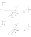
L=d1/tan(γ)+d/tan(δ)
と表すことができる。この実施形態では、レンズユニット4の上端面と原稿ガラスGLの下面との距離d1が0.66mm、原稿ガラスGLの厚みdが2.8mmに設定されているため、例えば、ライトガイド31の出射面31bの法線と原稿ガラスGLとが成す角度γを40度とすれば、出射面31bの中心とレンズユニット4の光軸CLとの距離Lは約2.4mmとなる。したがって、上記した条件において、出射面31bの中心および光軸CL間の距離が2.4mmとなるように、ライトガイド31およびレンズユニット4が配置されれば、出射面31bから出射される照明光により、原稿OBの光軸CLの位置が適正にX方向に帯状に照明される。
α+β+γ=270度
となるように、ライトガイド31およびレンズユニット4が配置されることによって、ライトガイド31の出射面31bから出射された光が原稿ガラスGLの上面とレンズユニット4の光軸CLとが交わる部分に帯状に照射される。
次に、図9(a),(b)を参照して比較例について説明する。図9は比較例における原稿の照明状態を説明するための図であって、(a)はライトガイドおよびレンズユニットの配置関係を示し、(b)は原稿の照明状態を示す。図9(a)に示すように、比較例では、ライトガイド131およびレンズユニット104は、それぞれ外周面に上記したような面取りが施されておらず、それぞれ長手方向(X方向)に直交する断面形状が矩形状に形成されている。また、長手方向に直交する断面におけるライトガイド131の出射面31bの幅は反射面31aと同じ幅に形成されている。その他の構成は上記した例と同様であるため、同一符号を付すことによりその説明を省略する。
次に、図10(a),(b)を参照してライトガイドの変形例(1)について説明する。図10はライトガイドの変形例(1)を示す図であって、(a),(b)はそれぞれ異なる変形例(1)を示す。図10(a)に示す例が図8(a)に示す例と異なるのは、ライトガイド310aの長手方向に直交する断面において、反射面31aが紙面に向かって時計方向に約10度傾いている点である。図10(b)に示す例が図8(a)に示す例と異なるのは、ライトガイド310bの長手方向に直交する断面において、反射面31aが紙面に向かって反時計方向に約10度傾いている点である。その他の構成は上記した例と同様であるため、同一符号を付すことによりその説明を省略する。
次に、図11(a),(b)を参照してライトガイドの変形例(2)について説明する。図11はライトガイドの変形例(2)における原稿の照明状態を説明するための図であって、(a)はライトガイドおよびレンズユニットの配置関係を示し、(b)は原稿の照明状態を示す。図11(a)に示す例が図8(a)に示す例と異なるのは、ライトガイド311の長手方向に直交する断面形状が、反射面31a側から出射面31b側に向けて先細りする台形状に形成されている点である。その他の構成は上記した例と同様であるため、同一符号を付すことによりその説明を省略する。
次に、図12(a),(b)を参照してライトガイドの変形例(3)について説明する。図12はライトガイドの変形例(3)における原稿の照明状態を説明するための図であって、(a)はライトガイドおよびレンズユニットの配置関係を示し、(b)は原稿の照明状態を示す。図12(a)に示す例が図8(a)に示す例と異なるのは、ライトガイド312の長手方向に直交する断面形状が、反射面31a側から出射面31b側に向けて先細りする五角形状に形成されている点である。その他の構成は上記した例と同様であるため、同一符号を付すことによりその説明を省略する。
次に、図13(a),(b)を参照してライトガイドの変形例(4)について説明する。図13はライトガイドの変形例(4)における原稿の照明状態を説明するための図であって、(a)はライトガイドおよびレンズユニットの配置関係を示し、(b)は原稿の照明状態を示す。図13(a)に示す例が図8(a)に示す例と異なるのは、ライトガイド313の長手方向に直交する断面形状が、反射面31a側から出射面31b側に向けて先細りする五角形状に形成されている点である。その他の構成は上記した例と同様であるため、同一符号を付すことによりその説明を省略する。
次に、図14(a),(b)を参照してライトガイドの変形例(5)について説明する。図14はライトガイドの変形例(5)における原稿の照明状態を説明するための図であって、(a)はライトガイドおよびレンズユニットの配置関係を示し、(b)は原稿の照明状態を示す。図14(a)に示す例が図13(a)に示す例と異なるのは、ライトガイド314の長手方向に直交する断面形状が、反射面31a側から出射面31b側に向けて先細りする五角形状に形成されているが、外周面の一部が曲面状に形成されている点である。その他の構成は上記した例と同様であるため、同一符号を付すことによりその説明を省略する。
次に、図15(a),(b)を参照してライトガイドの変形例(6)について説明する。図15はライトガイドの変形例(6)における原稿の照明状態を説明するための図であって、(a)はライトガイドおよびレンズユニットの配置関係を示し、(b)は原稿の照明状態を示す。図15(a)に示す例が図8(a)に示す例と異なるのは、長手方向に直交する断面が矩形状の棒状の透明部材の外周面のレンズユニット4に対向する部分が出射面31bに沿って長手方向に面取りされてライトガイド315が形成されることによって、その断面形状が反射面31a側から出射面31b側に向けて先細りする形状に形成されている点でる。そして、ライトガイド315の外周面の面取りされた部分と、レンズユニット4の面取りされた部分とが対向して配置されることによって、ライトガイド315およびレンズユニット4が近接配置されている。その他の構成は上記した例と同様であるため、同一符号を付すことによりその説明を省略する。
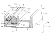
次に、図2および図3を参照しつつ図16〜図18を参照してフレームの成型方法の一例について説明する。図16はフレームを成型するための金型を示す斜視図、図17は図2に示すフレームの断面に相当する位置における金型の断面図、図18は図3に示すフレームの断面に相当する位置における金型の断面図である。フレーム2を成型するための金型200は、上部金型201と、下部金型202と、押さえ部材形成用ダイ203とを備えている。そして、上部金型201の下面には、中間部材21の上面側に斜溝22を形成するためのダイ201aおよび凹溝23を形成するためのダイ201bが設けられている。また、下部金型202の上面には中間部材21の下面形状を形成するためのダイ202aおよびスリット24を形成するためのダイ202bが設けられている。また、下部金型202には、紙面に向かって左側の側面から上面に連通する複数の斜孔202cが長手方向に沿って設けられており、各斜孔202cには、側面側から上面側にその先端が突出するように押さえ部材形成用ダイ203が挿入される。なお、下部金型202の上面から突出する各押さえ部材形成用ダイ203の先端の上面側の形状は、フレーム2の斜溝22に挿入されるライトガイド31の上側の周側面の形状とほぼ同一の形状に形成されている。押さえ部材25(斜溝22)を形成するための各押さえ部材形成用ダイ203の先端側の形状は、斜溝22に挿入されるライトガイド(導光体)の形状に応じた形状に適宜形成すればよい。
Claims (6)
- 光源の光を読み取りの対象物に導光する棒状の導光体を有し前記対象物を照明する照明手段と、
前記導光体に並設され、複数のレンズ面が前記導光体の長手方向と同方向に配列された入射面が設けられたレンズアレイを有し前記入射面に入射した前記対象物からの反射光を集光してセンサー上に正立等倍像を形成する結像光学素子と、
を備え、
前記導光体は、
透明部材により形成され、
当該導光体内に入射された前記光源の光を反射する反射構造が形成された反射面と、
前記反射面により反射された光を前記対象物に向けて出射する出射面と、を有し、
前記反射面および前記出射面は、それぞれ当該導光体の外周面に前記長手方向に沿って形成されて前記透明部材を介して対向配置され、
前記長手方向に直交する断面における前記出射面の幅は、前記反射面よりも狭く形成され、
前記結像光学素子は、前記導光体に対向する部分が前記レンズ面の配列方向に沿って面取りされた面取り部位を有し、
前記導光体は、前記結像光学素子に対向する部分が前記出射面に沿って前記長手方向に面取りされた面取り部位を有し、
前記導光体の前記出射面と前記結像光学素子の前記入射面とが近接配置され、
前記出射面は、前記結像光学素子の前記入射面を延長した面から突出しない
ことを特徴とする画像読取装置。 - 前記導光体の前記長手方向に直交する断面形状が前記反射面側から前記出射面側に向けて先細りする形状である請求項1に記載の画像読取装置。
- 前記結像光学素子は、前記結像光学素子の光軸を間に挟んで、前記導光体に対向する部分および前記導光体に対向しない部分が前記レンズ面の配列方向に沿って面取りされた面取り部位を有している請求項1または請求項2に記載の画像読取装置。
- 前記結像光学素子は、前記レンズアレイを収納するケース体をさらに有し、前記ケース体は、前記結像光学素子の前記面取り部位を有している請求項1ないし3のいずれかに記載の画像読取装置。
- 前記照明手段は、前記導光体の前記出射面を除く外周面を被覆する遮光フィルムをさらに有し、前記遮光フィルムの前記透明部材に接する面に光を散乱させる散乱面が形成されている請求項1ないし4のいずれかに記載の画像読取装置。
- 前記結像光学素子の前記導光体に対向する前記面取り部位と、前記導光体の前記結像光学素子に対向する前記面取り部位と、は当接するように設けられている請求項1ないし5のいずれかに記載の画像読取装置。
Priority Applications (6)
| Application Number | Priority Date | Filing Date | Title |
|---|---|---|---|
| JP2012086225A JP6155550B2 (ja) | 2012-04-05 | 2012-04-05 | 画像読取装置 |
| TW104131490A TWI582330B (zh) | 2012-04-05 | 2013-03-18 | 圖像讀取裝置 |
| TW102109534A TWI535966B (zh) | 2012-04-05 | 2013-03-18 | 圖像讀取裝置 |
| US13/852,252 US8908239B2 (en) | 2012-04-05 | 2013-03-28 | Image reading device |
| CN201310115793.7A CN103369185B (zh) | 2012-04-05 | 2013-04-03 | 图像读取装置 |
| US14/482,114 US9088684B2 (en) | 2012-04-05 | 2014-09-10 | Image reading device |
Applications Claiming Priority (1)
| Application Number | Priority Date | Filing Date | Title |
|---|---|---|---|
| JP2012086225A JP6155550B2 (ja) | 2012-04-05 | 2012-04-05 | 画像読取装置 |
Publications (3)
| Publication Number | Publication Date |
|---|---|
| JP2013219450A JP2013219450A (ja) | 2013-10-24 |
| JP2013219450A5 JP2013219450A5 (ja) | 2015-08-06 |
| JP6155550B2 true JP6155550B2 (ja) | 2017-07-05 |
Family
ID=49292094
Family Applications (1)
| Application Number | Title | Priority Date | Filing Date |
|---|---|---|---|
| JP2012086225A Active JP6155550B2 (ja) | 2012-04-05 | 2012-04-05 | 画像読取装置 |
Country Status (4)
| Country | Link |
|---|---|
| US (2) | US8908239B2 (ja) |
| JP (1) | JP6155550B2 (ja) |
| CN (1) | CN103369185B (ja) |
| TW (2) | TWI535966B (ja) |
Families Citing this family (7)
| Publication number | Priority date | Publication date | Assignee | Title |
|---|---|---|---|---|
| JP6155550B2 (ja) | 2012-04-05 | 2017-07-05 | セイコーエプソン株式会社 | 画像読取装置 |
| JP6028894B2 (ja) * | 2012-04-05 | 2016-11-24 | セイコーエプソン株式会社 | 画像読取装置および筐体の製造方法 |
| JP6230222B2 (ja) * | 2012-10-12 | 2017-11-15 | キヤノン株式会社 | レンズアレイ光学系及びレンズアレイの製造方法 |
| CN108055418A (zh) * | 2012-12-20 | 2018-05-18 | 三菱电机株式会社 | 图像读取装置 |
| JP6528989B2 (ja) * | 2015-06-01 | 2019-06-12 | 株式会社リコー | 照明装置、画像読取装置および画像形成装置 |
| JP7456092B2 (ja) * | 2019-03-26 | 2024-03-27 | 富士フイルムビジネスイノベーション株式会社 | 光学装置、画像読取装置、および画像形成装置 |
| CN110594692B (zh) * | 2019-09-25 | 2024-08-13 | 华域视觉科技(上海)有限公司 | 一种光导体组件、车灯模组和车辆 |
Family Cites Families (16)
| Publication number | Priority date | Publication date | Assignee | Title |
|---|---|---|---|---|
| JP4003893B2 (ja) * | 1996-12-27 | 2007-11-07 | ローム株式会社 | 画像読み取り装置 |
| JP3008267B2 (ja) * | 1997-01-30 | 2000-02-14 | ローム株式会社 | イメージセンサチップおよびイメージセンサ |
| FR2782779B1 (fr) * | 1998-05-15 | 2002-06-07 | Rohm Co Ltd | Dispositif de lecture d'images et dispositif d'eclairage utilise pour celui-ci |
| TW503646B (en) | 2000-03-16 | 2002-09-21 | Nippon Sheet Glass Co Ltd | Line illuminating device |
| CN2519560Y (zh) * | 2002-01-09 | 2002-10-30 | 山东华菱电子有限公司 | 图像读取装置 |
| JP4145271B2 (ja) | 2004-06-28 | 2008-09-03 | 日本板硝子株式会社 | 画像読取装置 |
| JP2006148501A (ja) * | 2004-11-19 | 2006-06-08 | Nippon Sheet Glass Co Ltd | 画像読取装置 |
| US8199377B2 (en) * | 2005-06-07 | 2012-06-12 | Nippon Sheet Glass Company, Limited | Image sensor and image reading device |
| CN101228779A (zh) * | 2005-09-08 | 2008-07-23 | 三菱电机株式会社 | 图像读取装置 |
| US7659503B2 (en) * | 2007-08-02 | 2010-02-09 | Rohm Co., Ltd. | Image sensor module and light guiding member used for the same |
| JP2010021983A (ja) | 2007-12-21 | 2010-01-28 | Rohm Co Ltd | 導光体、導光体の製造方法、および画像読取装置 |
| JP5342197B2 (ja) * | 2008-08-26 | 2013-11-13 | ローム株式会社 | 画像読み取り装置 |
| JP2010130056A (ja) * | 2008-11-25 | 2010-06-10 | Ricoh Co Ltd | 光照射装置、画像読取装置および画像形成装置 |
| JP5609361B2 (ja) * | 2010-07-21 | 2014-10-22 | 富士ゼロックス株式会社 | 導光体及び画像読取装置 |
| JP6155550B2 (ja) | 2012-04-05 | 2017-07-05 | セイコーエプソン株式会社 | 画像読取装置 |
| JP6102091B2 (ja) | 2012-06-21 | 2017-03-29 | セイコーエプソン株式会社 | 画像読取装置 |
-
2012
- 2012-04-05 JP JP2012086225A patent/JP6155550B2/ja active Active
-
2013
- 2013-03-18 TW TW102109534A patent/TWI535966B/zh active
- 2013-03-18 TW TW104131490A patent/TWI582330B/zh active
- 2013-03-28 US US13/852,252 patent/US8908239B2/en active Active
- 2013-04-03 CN CN201310115793.7A patent/CN103369185B/zh active Active
-
2014
- 2014-09-10 US US14/482,114 patent/US9088684B2/en active Active
Also Published As
| Publication number | Publication date |
|---|---|
| JP2013219450A (ja) | 2013-10-24 |
| TW201610338A (zh) | 2016-03-16 |
| TWI535966B (zh) | 2016-06-01 |
| TW201341705A (zh) | 2013-10-16 |
| US20140376066A1 (en) | 2014-12-25 |
| CN103369185B (zh) | 2015-11-25 |
| TWI582330B (zh) | 2017-05-11 |
| US20130265619A1 (en) | 2013-10-10 |
| US8908239B2 (en) | 2014-12-09 |
| CN103369185A (zh) | 2013-10-23 |
| US9088684B2 (en) | 2015-07-21 |
Similar Documents
| Publication | Publication Date | Title |
|---|---|---|
| JP6028894B2 (ja) | 画像読取装置および筐体の製造方法 | |
| JP6155550B2 (ja) | 画像読取装置 | |
| US9462150B2 (en) | Image read-in device with fastener to fasten transparent member retaining lens array assembly and light shield to board | |
| US6717734B2 (en) | Image forming lens unit and image reading apparatus using the same | |
| JP2001238048A (ja) | 画像読み取り装置およびこれに用いる導光部材 | |
| US20120188616A1 (en) | Image Reading Device | |
| CN111756948B (zh) | 光学设备、图像读取设备和图像形成装置 | |
| US20120200900A1 (en) | Imaging Optical Array And Image Reading Device | |
| TW200532952A (en) | Line-illuminating device and image-scanning device incorporating the same | |
| JP2013219450A5 (ja) | ||
| JPH1175015A (ja) | イメージセンサ | |
| CN111756947A (zh) | 光学设备、图像读取设备及图像形成装置 | |
| JP6060937B2 (ja) | 画像読取装置 | |
| JP2014003570A (ja) | 画像読取装置 | |
| CN111830805B (zh) | 光学装置、图像读取装置及图像形成装置 | |
| JP6102080B2 (ja) | 画像読取装置 | |
| JP5402559B2 (ja) | イメージセンサ | |
| CN110785988B (zh) | 导光体及图像读取装置 | |
| JP5000535B2 (ja) | イメージセンサモジュール | |
| JP2001223844A (ja) | イメージセンサおよびこれを備えたハンディスキャナ | |
| JP2005234271A (ja) | 光学読取用レンズアレイ | |
| JP2001217992A (ja) | 画像読み取り装置 | |
| JPH03225318A (ja) | 結像装置 |
Legal Events
| Date | Code | Title | Description |
|---|---|---|---|
| RD04 | Notification of resignation of power of attorney |
Free format text: JAPANESE INTERMEDIATE CODE: A7424 Effective date: 20150107 |
|
| A621 | Written request for application examination |
Free format text: JAPANESE INTERMEDIATE CODE: A621 Effective date: 20150401 |
|
| A521 | Written amendment |
Free format text: JAPANESE INTERMEDIATE CODE: A523 Effective date: 20150617 |
|
| A977 | Report on retrieval |
Free format text: JAPANESE INTERMEDIATE CODE: A971007 Effective date: 20160415 |
|
| A131 | Notification of reasons for refusal |
Free format text: JAPANESE INTERMEDIATE CODE: A131 Effective date: 20160426 |
|
| A521 | Written amendment |
Free format text: JAPANESE INTERMEDIATE CODE: A523 Effective date: 20160513 |
|
| RD04 | Notification of resignation of power of attorney |
Free format text: JAPANESE INTERMEDIATE CODE: A7424 Effective date: 20160609 |
|
| RD03 | Notification of appointment of power of attorney |
Free format text: JAPANESE INTERMEDIATE CODE: A7423 Effective date: 20160617 |
|
| A131 | Notification of reasons for refusal |
Free format text: JAPANESE INTERMEDIATE CODE: A131 Effective date: 20161025 |
|
| TRDD | Decision of grant or rejection written | ||
| A01 | Written decision to grant a patent or to grant a registration (utility model) |
Free format text: JAPANESE INTERMEDIATE CODE: A01 Effective date: 20170509 |
|
| A61 | First payment of annual fees (during grant procedure) |
Free format text: JAPANESE INTERMEDIATE CODE: A61 Effective date: 20170522 |
|
| R150 | Certificate of patent or registration of utility model |
Ref document number: 6155550 Country of ref document: JP Free format text: JAPANESE INTERMEDIATE CODE: R150 |


