JP6139815B2 - Workpiece processing system and method - Google Patents
Workpiece processing system and method Download PDFInfo
- Publication number
- JP6139815B2 JP6139815B2 JP2010522450A JP2010522450A JP6139815B2 JP 6139815 B2 JP6139815 B2 JP 6139815B2 JP 2010522450 A JP2010522450 A JP 2010522450A JP 2010522450 A JP2010522450 A JP 2010522450A JP 6139815 B2 JP6139815 B2 JP 6139815B2
- Authority
- JP
- Japan
- Prior art keywords
- workpiece
- feed
- workpiece processing
- printing
- input
- Prior art date
- Legal status (The legal status is an assumption and is not a legal conclusion. Google has not performed a legal analysis and makes no representation as to the accuracy of the status listed.)
- Expired - Fee Related
Links
Images


Classifications
-
- B—PERFORMING OPERATIONS; TRANSPORTING
- B41—PRINTING; LINING MACHINES; TYPEWRITERS; STAMPS
- B41F—PRINTING MACHINES OR PRESSES
- B41F15/00—Screen printers
- B41F15/08—Machines
-
- H—ELECTRICITY
- H05—ELECTRIC TECHNIQUES NOT OTHERWISE PROVIDED FOR
- H05K—PRINTED CIRCUITS; CASINGS OR CONSTRUCTIONAL DETAILS OF ELECTRIC APPARATUS; MANUFACTURE OF ASSEMBLAGES OF ELECTRICAL COMPONENTS
- H05K13/00—Apparatus or processes specially adapted for manufacturing or adjusting assemblages of electric components
- H05K13/0061—Tools for holding the circuit boards during processing; handling transport of printed circuit boards
-
- H—ELECTRICITY
- H05—ELECTRIC TECHNIQUES NOT OTHERWISE PROVIDED FOR
- H05K—PRINTED CIRCUITS; CASINGS OR CONSTRUCTIONAL DETAILS OF ELECTRIC APPARATUS; MANUFACTURE OF ASSEMBLAGES OF ELECTRICAL COMPONENTS
- H05K3/00—Apparatus or processes for manufacturing printed circuits
- H05K3/10—Apparatus or processes for manufacturing printed circuits in which conductive material is applied to the insulating support in such a manner as to form the desired conductive pattern
- H05K3/12—Apparatus or processes for manufacturing printed circuits in which conductive material is applied to the insulating support in such a manner as to form the desired conductive pattern using thick film techniques, e.g. printing techniques to apply the conductive material or similar techniques for applying conductive paste or ink patterns
- H05K3/1216—Apparatus or processes for manufacturing printed circuits in which conductive material is applied to the insulating support in such a manner as to form the desired conductive pattern using thick film techniques, e.g. printing techniques to apply the conductive material or similar techniques for applying conductive paste or ink patterns by screen printing or stencil printing
Description
本発明は、ワークピースを、特定的には基板を、より特定的にはプリント回路基板や太陽電池ウェハを含むウェハ等の電子基板を処理するワークピース処理システム及び方法に関し、特に、ワークピースに印刷するスクリーン印刷システム及び方法に関する。 The present invention relates to a workpiece processing system and method for processing a workpiece, particularly a substrate, more specifically an electronic substrate such as a wafer including a printed circuit board or a solar cell wafer, and more particularly to a workpiece. The present invention relates to a screen printing system and method for printing.
電子産業における、基板を複雑多層化し、基板へより多くの部品を装着し、基板内で配線を増加させる一般的傾向によって、精密さ及び処理能力の両方の観点において処理動作、特に印刷動作に対する要求が高まっている。 Due to the general tendency of the electronics industry to complex multiple layers of boards, mount more components on the board, and increase the wiring within the board, the demand for processing operations, especially printing operations, both in terms of precision and throughput Is growing.
SMT製造には3つの基本的プロセスが含まれる。つまり、はんだ堆積物の印刷を含む基板への材料堆積物の印刷、印刷された基板への部品の装着、及び印刷された堆積物のリフローである。 SMT manufacturing involves three basic processes. That is, printing material deposits on the substrate, including printing solder deposits, mounting components on the printed substrate, and reflowing the printed deposits.
製造設備には機械がインライン構成で含まれ、機械間を通行するコンベヤによって機械は相互に接続される。基板は、最初に材料堆積物を印刷する印刷機へと渡り、次にピック−アンド−プレース機へと渡り、そこで印刷された基板に部品が装着され、最後にリフロー機へと渡り、組立品が均質化される。 Manufacturing equipment includes machines in an in-line configuration, and the machines are interconnected by a conveyor that passes between the machines. The board first passes to the printing machine that prints the material deposit, then to the pick-and-place machine, where the components are mounted on the printed board, and finally to the reflow machine, the assembly. Is homogenized.
処理能力を高め、生産性への高まる要求を満たすための近年の開発は、多様な機械の生産量を高めるためのものであった。これは、各機械工程の時間及び工程間の時間を短縮し、機械に多数のトラックを設けることによって達成されてきた。このような多数トラックの印刷機では、印刷スクリーンが各トラック当たり1枚ずつの複数の画像を含み、これによって、一回の印刷動作で同時に複数の基板に堆積物のパターンを印刷することが可能となる。 Recent developments to increase processing capacity and meet growing demands for productivity have been to increase the output of various machines. This has been accomplished by reducing the time of each machine process and the time between processes and providing the machine with a large number of tracks. In such a multi-track printing machine, the printing screen contains multiple images, one for each track, which allows a pattern of deposits to be printed on multiple substrates simultaneously in a single printing operation. It becomes.
このようなマルチトラック印刷機によって処理能力は高められたが、単一の印刷スクリーンを使用してワークピースを順次に処理することを前提とすると処理能力の向上には限界がある。 Although such multi-track printing presses have increased throughput, there is a limit to improving throughput if it is assumed that workpieces will be processed sequentially using a single printing screen.
太陽電池の製造では、ウェハの上下面へ画像を印刷し、その後に印刷されたウェハを焼成することが必要とされる。典型的には、ウェハの上面に1枚の画像を印刷し、ウェハの下面に2枚の画像を印刷する。 In the manufacture of solar cells, it is necessary to print images on the upper and lower surfaces of the wafer and then to fire the printed wafer. Typically, one image is printed on the upper surface of the wafer and two images are printed on the lower surface of the wafer.
このような処理をするべく、従来の生産ラインは9台の独立した処理機械を含む。これらは、生産ラインにウェハを載せるウェハローダと、ウェハの一面に第1のプリントを印刷する第1の印刷機と、印刷されたウェハを乾燥させる第1の乾燥機と、ウェハを反転させるフリッパと、ウェハの他面に第2のプリントを印刷する第2の印刷機と、印刷されたウェハを乾燥させる第2の乾燥機と、ウェハの他面に第3のプリントを印刷する第3の印刷機と、印刷されたウェハを焼成する焼成炉と、完成したウェハを生産ラインから降ろすアンローダとである。多数の独立した機械が必要とされるだけでなく、これらによって大面積が必要となる。 In order to perform such processing, a conventional production line includes nine independent processing machines. These include a wafer loader that places a wafer on a production line, a first printer that prints a first print on one side of the wafer, a first dryer that dries the printed wafer, and a flipper that inverts the wafer. A second printing machine for printing a second print on the other side of the wafer, a second dryer for drying the printed wafer, and a third printing for printing a third print on the other side of the wafer. A firing machine for firing the printed wafer, and an unloader for unloading the completed wafer from the production line. Not only are a large number of independent machines required, but these require a large area.
近年、太陽電池ウェハにコンタクトフィンガーを印刷するためのホット−メルト印刷処理が開発され、これによって乾燥工程の必要性が排除される。ホット−メルト印刷を利用すると、従来の乾燥機が必要とされないので独立した機械の台数が7台に減る。しかし、依然として多数の機械が必要とされ、そのため大面積が必要である。 In recent years, hot-melt printing processes have been developed for printing contact fingers on solar cell wafers, thereby eliminating the need for a drying step. Utilizing hot-melt printing reduces the number of independent machines to seven because a conventional dryer is not required. However, a large number of machines are still required, and thus a large area is required.
本発明は、ワークピースの高処理能力を可能とするワークピース処理システム及び方法、特にワークピース印刷システム及び方法を提供することを目的とする。 It is an object of the present invention to provide a workpiece processing system and method, particularly a workpiece printing system and method, which allows for high workpiece throughput.
また、本発明は、複数のワークピース処理モジュールを含み、ワークピースの処理経路の設定において、たとえばワークピース処理モジュールの負荷の分散において融通性を提供し、ワークピース処理モジュールが、たとえば印刷やボール装着等の異なる種類のワークピース処理を提供し、2以上の出力ラインにワークピースが供給され、各出力ラインには異なる個数のワークピースが提供される、ワークピース処理システム及び方法、特にワークピース印刷システム及び方法を提供することを目的とする。
Further, the present invention includes a plurality of The workpiece, processing module, in setting the processing path of the workpiece, for example, provide flexibility in distributing the load of the The workpiece, processing module, is The workpiece, processing module, e.g. provides printing and ball instrumentation wearing different types of workpiece handling of such, is supplied
また特に、本発明は、ウェハ、特に太陽電池ウェハの印刷を、従来の印刷機と類似したサイズの単一の機械によって提供することにより、生産に必要とされるスペースを大幅に削減するワークピース印刷システム及び方法を提供することを目的とする。 More particularly, the present invention provides a workpiece that significantly reduces the space required for production by providing printing of wafers, particularly solar cell wafers, with a single machine similar in size to conventional printing presses. It is an object to provide a printing system and method.
1つの観点においては、本発明は、少なくとも1つのワークピース処理モジュールを含むワークピース処理システムであって、各ワークピース処理モジュールが、ワークピースを処理するワークピース処理ユニットと、ワークピース処理ユニットへと/から、ワークピースを移送するべく動作可能なフィードユニットとを含み、フィードユニットが、ワークピース処理ユニットへと/から、ワークピースを移送するべく動作可能な入力側及び出力側フィードアセンブリと、入力側及び出力側フィードアセンブリを相互接続し、入力側フィードアセンブリからワークピース処理ユニットへと、またワークピース処理ユニットから少なくとも1つの出力側フィードアセンブリへと、ワークピースを移送するべく動作可能な処理域フィードアセンブリとを含むことを特徴とするワークピース処理システムを提供する。 In one aspect, the present invention is a workpiece processing system that includes at least one workpiece processing module, each workpiece processing module processing a workpiece, and a workpiece processing unit. And a feed unit operable to transfer the workpiece, wherein the feed unit is operable to transfer the workpiece to / from the workpiece processing unit; A process operable to interconnect the input and output feed assemblies and to transfer the workpiece from the input feed assembly to the workpiece processing unit and from the workpiece processing unit to at least one output feed assembly. Area feed assembly Providing a work piece processing system which comprises and.
別の観点においては、本発明は、複数のワークピース処理モジュールを含み、それぞれのワークピース処理モジュールが、ワークピースを処理するワークピース処理ユニットと、ワークピース処理ユニットへと/から、ワークピースを移送するべく動作可能なフィードユニットとを含むことを特徴とするワークピース処理システムを提供する。 In another aspect, the invention includes a plurality of workpiece processing modules, each workpiece processing module processing a workpiece into and out of a workpiece processing unit that processes the workpiece. A workpiece processing system is provided that includes a feed unit operable to be transported.
本発明は、上記のワークピース処理システムを使用するワークピース処理方法へも拡張される。 The present invention also extends to a workpiece processing method using the workpiece processing system described above.
さらなる観点においては、本発明は、ワークピース処理ステーションと、ワークピース処理ステーションへと/から、ワークピースを移送する入力側及び出力側フィードアセンブリと、入力側及び出力側フィードアセンブリを相互接続し、入力側フィードアセンブリからワークピース処理ステーションへと、またワークピース処理ステーションから少なくとも1つの出力側フィードアセンブリへとワークピースを移送する処理域フィードアセンブリとをそれぞれが含む少なくとも1つのワークピース処理モジュールを設ける工程と、入力側フィードアセンブリ上で、少なくとも1つのワークピース処理モジュールへとワークピースをフィードする工程と、少なくとも1つの出力側フィードアセンブリ上で、少なくとも1つのワークピース処理モジュールからワークピースをフィードする工程と、処理域フィードアセンブリ上で、入力側フィードアセンブリからワークピース処理ステーションへと、また少なくとも1つの出力側フィードアセンブリへと、ワークピースをフィードする工程とを含むことを特徴とするワークピース処理方法を提供する。 In a further aspect, the present invention interconnects a workpiece processing station, an input and output feed assembly for transferring the workpiece to and from the workpiece processing station, and an input and output feed assembly; At least one workpiece processing module is provided that each includes a process area feed assembly that transfers the workpiece from the input feed assembly to the workpiece processing station and from the workpiece processing station to at least one output feed assembly. a step, on the input side feed assembly, comprising the steps of feeding into at least one workpiece handling module workpieces, on at least one output-side feed assembly, at least one workpiece handling A step of feeding a workpiece from Joules on the treatment zone feed assembly, and from the input side feed assembly to the workpiece processing station, also to at least one output feeding assembly, to a step of feeding a workpiece A workpiece processing method is provided.
またさらなる観点においては、本発明は、ワークピースを処理するワークピース処理ユニットをそれぞれが含む複数のワークピース処理モジュールを設ける工程と、ワークピース処理ユニットへと/から、ワークピースを移送する工程とを含むワークピース処理方法を提供する。 In yet a further aspect, the present invention includes providing a plurality of workpiece processing modules each including a workpiece processing unit for processing a workpiece, and transferring the workpiece to / from the workpiece processing unit. A workpiece processing method is provided.
添付の図面を参照して、本発明の好適な実施の形態を例示目的のみにおいて以下に記載する。 Preferred embodiments of the invention will now be described, by way of example only, with reference to the accompanying drawings.
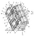
図1〜4は、本発明の第1の実施の形態に係る、本実施の形態においてはスクリーン印刷システムであるワークピース−処理システムを示す。 1-4 show a workpiece-processing system according to a first embodiment of the present invention, which in this embodiment is a screen printing system.
スクリーン印刷システムは、少なくとも1つのワークピース−処理モジュール3、本実施の形態においては複数のワークピース−処理モジュール3a、3b、3cを含む。ここでは、これらは平行に配置された印刷モジュールであり、各々が印刷媒体の堆積物をワークピースWへと印刷するべく独自に動作可能である。
The screen printing system includes at least one workpiece-
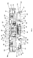
各印刷モジュール3a、3b、3cは、支持ユニット5を含む。支持ユニット5は、地面に置かれる、本実施の形態においては枠部材である下部基礎支持部材7と、下部支持部材7に取り付けられる、本実施の形態においては枠部材である上部支持部材9とを含む。
Each
本実施の形態においては、印刷モジュール3a、3b、3cの下部支持部材7は、単一の一体型構造体として提供される。別の実施の形態においては、印刷モジュール3a、3b、3cの下部支持部材7は、固定ボルトによって一緒に固定される等、一緒に固定された別個の構造体であってもよい。
In the present embodiment, the
本実施の形態においては、印刷モジュール3a、3b、3cの上部支持部材9は、別個の構造体として提供される。
In the present embodiment, the
各印刷モジュール3a、3b、3cは、上部支持部材9に搭載され、印刷媒体の堆積物を連続するワークピースWへと印刷するべく動作可能な、本実施の形態においては印刷ユニットである、ワークピース−処理ユニット11をさらに含む。
Each
印刷ユニット11は、印刷スクリーンPSを支持するスクリーン支持部材15と、印刷スクリーンPS上を移動して、下に支持されるワークピースWへと印刷スクリーンPSの開口パターンを通じて印刷媒体の堆積物を印刷する印刷ヘッド19と、印刷動作時に印刷ヘッド19を印刷スクリーンPS上で駆動する駆動機構21とを含む。
The
本実施の形態においては、印刷ヘッド19はエンクローズド(enclosed)な印刷ヘッドであり、反対し合う各運動方向に印刷するべく印刷スクリーンPS上を往復駆動可能である。別の実施の形態においては、印刷ヘッド19はスキージ等のその他の適切な設計であってよく、1つの運動方向にのみ印刷するべく動作可能であってよい。
In the present embodiment, the
図2及び3に詳しく示すように、各印刷モジュール3a、3b、3cは、ワークピースWを受け取り、それを印刷スクリーンPSの下に支持するワークピース−支持アセンブリ22をさらに含む。
As shown in detail in FIGS. 2 and 3, each
ワークピース−支持アセンブリ22は、ワークピースWを支持するワークピース−支持ユニット23と、支持されたワークピースWを印刷スクリーンPSに対して整列させるアライメント機構24とを含む。
Workpiece - the
ワークピース−支持ユニット23は、垂直に移動可能で印刷ステーションを提供するワークピース−支持部材25と、ワークピース−支持部材25を昇降させるべく動作可能なリフト機構26とを含む。
Workpiece - the
本実施の形態においては、ワークピース−支持部材25は、ワークピース−支持部材25にワークピースWを積み込むことができる第1の下降した積み込み位置と、印刷のためにワークピースWが印刷スクリーンPSの下の位置に設定される第2の上昇したワークピース−処理位置、ここでは印刷位置との間を移動することができる。本発明の印刷システムは、接触型及び非接触型の両方の印刷を可能にする。
In the present embodiment, the work piece - the
本実施の形態においては、ワークピース−支持部材25は、ワークピース−処理テーブル27、ここでは印刷テーブルを、本実施の形態では、ワークピースWをそこへと保持するべく作用する、ここでは中央に位置付けられる真空部28を含むプラテンという形態で含む。
In the present embodiment, the work piece - the
本実施の形態においては、真空部28はパッドを含む。パッドは、ここでは焼結プレートであり、典型的には焼結セラミックプレートである。パッドは、平面的な上面を定めるべく印刷テーブル27の中に設定され、その下面へ真空源が印加されるとその上面で真空をもたらすものである。
In the present embodiment, the
本実施の形態においては、ワークピース−支持部材25は、印刷テーブル27を貫通して延びる、ここでは圧縮バネである弾性要素30によって下方に付勢される複数のワークピース−支持要素29、ここでは直立支柱をさらに含む。
In the present embodiment, the work piece - the
本実施の形態においては、印刷テーブル27が下降した積み込み位置にあるときには、弾性要素30が圧縮され、ワークピース−支持要素29が印刷テーブル27の上面上に突出して、ワークピースWを印刷テーブル27の上面から離間させてワークピース−支持要素29上に受け止めるように、また、印刷テーブル27が上昇した印刷位置にあるときには、ワークピース−支持要素29が印刷テーブル27の上面もしくは上面下に、ここでは印刷テーブル27の上面に同一平面的に位置し、それによってワークピースWの下面が印刷テーブル27の上面に完全に支持されるように、弾性要素30は各ストップ31に対して作用するべく構成される。
In the present embodiment, when the print table 27 is in the loading position lowered, the
本実施の形態においては、印刷テーブル27は少なくとも1つの、ここでは複数のウィンドウ32を含み、これによって、支持されたワークピースWの縁部と、印刷スクリーンPSの下面における、しばしば基準(fiducials)と呼ばれるアライメントマークとへの視線が与えられる。
In the present embodiment, the printing table 27 includes at least one, here a plurality of
本実施の形態においては、リフト機構26は、リードスクリュー33と、リードスクリュー33を回転させるアクチュエータ34とを含む。リードスクリュー33は、時計回り及び反時計回りの反対し合う方向にリードスクリュー33を回転させることにより印刷テーブル27の上昇又は下降のいずれかが生じるように、印刷テーブル27に螺合される。
In the present embodiment, the
本実施の形態においては、アクチュエータ34は、駆動モータと、付随するギアボックスアセンブリとを含む。
In the present embodiment,
本実施の形態においては、アライメント機構24は、少なくとも1つの、本実施の形態においては複数のカメラユニット35と、アクチュエータユニット36とを含む。カメラユニット35は、印刷テーブル27の各ウィンドウ32を通して、支持されたワークピースWの縁部と、印刷スクリーンPSの下面のアライメントマークとを観察するべく構成される。アクチュエータユニット36は、カメラユニット35により取得された画像に応じて、印刷スクリーンPSに対する支持されたワークピースWの整列ずれがあればそれを修正するべく動作可能な複数のアクチュエータ、ここでは駆動モータを含む。
In the present embodiment, the
本実施の形態においては、アクチュエータユニット36は、ワークピースWをX、Y、及びθ軸に位置決めする3つのアクチュエータを含む。その他の実施の形態においては、アクチュエータユニット36は、印刷スクリーンPSに対して支持されたワークピースWが整列することが可能となる任意の数及び配列のアクチュエータを含んでよい。
In the present embodiment, the
本実施の形態においては、印刷スクリーンPSに対してワークピースWが整列することが達成されるようにするべく印刷スクリーンPSに対してワークピースWを移動させる。しかし、別の実施の形態においては、印刷スクリーンPSに対してワークピースWが整列することが達成されるようにするべくワークピースWに対して印刷スクリーンPSを移動させてもよい。 In the present embodiment, the workpiece W is moved with respect to the printing screen PS so that the alignment of the workpiece W with respect to the printing screen PS is achieved. However, in another embodiment, the printing screen PS may be moved relative to the workpiece W to achieve alignment of the workpiece W with respect to the printing screen PS.
各印刷モジュール3a、3b、3cは、ワークピースWを印刷ユニット11へと/から移送するべく動作可能な、上部支持部材9に取り付けられるフィードユニット37をさらに含む。
Each
フィードユニット37は、入力側及び出力側フィードアセンブリ38、39と、印刷域フィードアセンブリ40とを含む。入力側及び出力側フィードアセンブリ38、39は、本実施の形態においては、印刷ユニット11の互いに反対側に平行に配置され、印刷モジュール3a、3b、3cへと/からワークピースWを移送するべく動作可能である。印刷域フィードアセンブリ40は、入力側及び出力側フィードアセンブリ38、39を相互接続し、印刷のために入力側フィードアセンブリ38からワークピース−支持ユニット23のワークピース−支持部材25へと、印刷後にはワークピース−支持ユニット23のワークピース−支持部材25から出力側フィードアセンブリ39へと、ワークピースWを移送するべく動作可能である。
The
本実施の形態においては、入力側及び出力側フィードアセンブリ38、39は、共通のフィード方向F1、F2にワークピースWをフィードするべく動作可能であるが、別の実施の形態においては、フィード方向F1、F2は、反対方向であってよい。
In this embodiment, the input and output
図2に詳しく示すように、入力側フィードアセンブリ38は、個別に動作可能な第1、第2、第3のサブ−フィードアセンブリ38a、38b、38cを含む。以下により詳しく記載するように、入力側フィードアセンブリ38の主機能は、印刷域フィードアセンブリ40へと移送するべくワークピースWを保持し、また、いずれか下流の印刷モジュール3a、3b、3cへとワークピースWを移送することである。
As shown in detail in FIG. 2, the
第1の積み込みサブ−フィードアセンブリ38aは、積み込みステーションを提供し、積み込みステーションからワークピースWを印刷ユニット11へと積み込むことができる。
The first loading
第2のアップラインバッファサブ−フィードアセンブリ38bは、積み込みサブ−フィードアセンブリ38aの上流にあり、積み込みサブ−フィードアセンブリ38aへと下流に移送するべくワークピースWを一時保管するアップラインバッファステーションを提供する。
The second upline buffer
第3のダウンラインバッファサブ−フィードアセンブリ38cは、積み込みサブ−フィードアセンブリ38aの下流にあり、下流へと移送するべくワークピースWを一時保管するダウンラインバッファステーションを提供する。
The third downline buffer sub-feed assembly 38c is downstream of the loading
各サブ−フィードアセンブリ38a、38b、38cは、本実施の形態においてはベルトであり、ここでは歯付きベルトである、1対の駆動要素41、41と、本実施の形態においては駆動モータであるアクチュエータ45とを含む。1対の駆動要素41、41は、ワークピースWの互いに反対側の下端と係合するべく離間して平行に配置される。アクチュエータ45は、駆動要素41、41がアクチュエータ45によって共通に駆動されるように、本実施の形態ではプーリ配列47によって駆動要素41、41へと共通に結合される。
Each
本実施の形態においては、第1の積み込みサブ−フィードアセンブリ38aの内側駆動要素41は、ここではプーリの配列によって構成され、それにより、以下により詳しく記載するように、間に移動ビーム95を収容する第1及び第2の離間した駆動要素部を含む。
In the present embodiment, the
各サブ−フィードアセンブリ38a、38b、38cは、入力側フィード方向F1を下流として配置された第1及び第2のセンサ53、55を含むセンサユニット51をさらに含む。ワークピースWの前縁部が第1の上流側センサ53によって検出されるまでは第1の移送速度でアクチュエータ45が駆動要素41、41を駆動し、ワークピースWの前縁部が第1のセンサ53によって検出されると、第2のより遅い速度でアクチュエータ45が駆動要素41、41を駆動するようにセンサ53、55は構成される。これによって、ワークピースWが正確に位置決めされる。ワークピースWの前縁部が第2の下流側センサ55によって検出されると、要求される位置にワークピースWを位置決めするべくアクチュエータ45を停止させる。
Each
出力側フィードアセンブリ39は、個別に動作可能な第1、第2、第3のサブ−フィードアセンブリ39a、39b、39cを含む。以下により詳しく記載するように、出力側フィードアセンブリ39の主機能は、印刷域フィードアセンブリ40からワークピースWを受け取り、それを下流へと移送することである。
The output
第1の積み出しサブ−フィードアセンブリ39aは、積み出しステーションを提供し、ワークピースWは、印刷ユニット11から積み出しステーションへと降ろされる。
The first unloading
第2のアップラインバッファサブ−フィードアセンブリ39bは、積み出しサブ−フィードアセンブリ39aの上流にあり、下流へと移送するべくワークピースWを一時保管するアップラインバッファステーションを提供する。
The second upline buffer sub-feed assembly 39b is upstream of the unloading
第3のダウンラインバッファサブ−フィードアセンブリ39cは、積み出しサブ−フィードアセンブリ39aの下流にあり、下流へと移送するべくワークピースWを一時保管するダウンラインバッファステーションを提供する。
The third downline buffer sub-feed assembly 39c is downstream of the unloading
各サブ−フィードアセンブリ39a、39b、39cは、本実施の形態においてはベルトであり、ここでは歯付きベルトである、1対の駆動要素61、61と、本実施の形態においては駆動モータであるアクチュエータ65とを含む。1対の駆動要素61、61は、ワークピースWの互いに反対側の下端と係合するべく離間して平行に配置される。アクチュエータ65は、駆動要素61、61がアクチュエータ65によって共通に駆動されるように、本実施の形態ではプーリ配列67によって駆動要素61、61へと共通に結合される。
Each
本実施の形態においては、第1の積み出しサブ−フィードアセンブリ39aの内側駆動要素61は、ここではプーリの配列によって構成され、それにより、以下により詳しく記載するように、間に移動ビーム135を収容する第1及び第2の離間した駆動要素部を含む。
In this embodiment, the
各サブ−フィードアセンブリ39a、39b、39cは、出力側フィード方向F2を下流として配置された第1及び第2のセンサ73、75を含むセンサユニット71をさらに含む。ワークピースWの前縁部が第1の上流側センサ73によって検出されるまでは第1の移送速度でアクチュエータ65が駆動要素61、61を駆動し、ワークピースWの前縁部が第1のセンサ73によって検出されると、第2のより遅い速度でアクチュエータ65が駆動要素61、61を駆動するようにセンサ73、75は構成される。これによって、ワークピースWが正確に位置決めされる。ワークピースWの前縁部が第2の下流側センサ75によって検出されると、要求される位置にワークピースWを位置決めするべくアクチュエータ65を停止させる。
Each
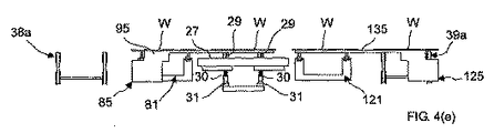
図2及び3に詳しく示すように、印刷域フィードアセンブリ40は、積み込みステーション38aに隣接して、本実施の形態においては内側に隣接して配置される入力側移送ステーション81と、積み込みステーション38aから入力側移送ステーション81へと、また入力側移送ステーション81から印刷ステーションへとワークピースWを移送するべく動作可能な入力側移送ユニット85とを含む。
As shown in detail in FIGS. 2 and 3, the print
本実施の形態においては、入力側移送ステーション81は、四角形の形態に配列される、複数のワークピース−支持要素87、ここでは4つの固定された直立支柱を含む。別の実施の形態においては、ワークピースWを支持する任意の数及び構成のワークピース−支持要素87を使用してよい。
In this embodiment, the input
本実施の形態においては、入力側移送ユニット85は、第1のワークピースWを積み込みステーション38aから入力側移送ステーション81へと、第2のワークピースWを入力側移送ステーション81から印刷ステーションへと移送するべく動作可能であり、本実施の形態においては、入力側移送ユニット85は、第1及び第2のワークピースWを同時に移送するよう構成される。
In the present embodiment, the input-
本実施の形態においては、入力側移送ユニット85は、移動−ビームアセンブリであり、固定された主支持体91と、主支持体91に対して移動可能な移動体93と、移動体93を昇降させるリフト機構97と、移動支持体93を水平に移動させる水平駆動機構101とを含む。移動体93は、水平な移動ビーム95を、本実施の形態においては移動体93の上面に含む。
In the present embodiment, the input-
本実施の形態においては、移動体93は軸受により主支持体91上に支持され、これにより移動体93が主支持体91に対して垂直及び水平に摺動することが可能となる。 In the present embodiment, the moving body 93 is supported on the main support body 91 by a bearing, whereby the moving body 93 can slide vertically and horizontally with respect to the main support body 91.
本実施の形態においては、移動ビーム95は、ワークピースWをそこへと真空により保持することが可能な第1及び第2の真空部103、104を含む。
In the present embodiment, the moving
本実施の形態においては、真空部103、104は、移動ビーム95の上面へと延伸する、真空源が当該上面に印加されると当該上面において真空をもたらす複数の開口部を含む。
In the present embodiment, the
本実施の形態においては、リフト機構97は、カム105と、アクチュエータ107とを含むカム機構である。アクチュエータ107は、本実施の形態においては駆動モータであり、第1の下降した位置と、第2の上昇した位置との間でカム105を駆動するべく動作可能である。第1の下降した位置では、移動体93は第1の下降した位置に存在し、この位置では移動ビーム95はその上に置かれるワークピースWから離れている。第2の上昇した位置では、移動体93は第2の上昇した位置に存在し、この位置では移動ビーム95はその上に置かれるワークピースWを支持する。
In the present embodiment, the
本実施の形態においては、カム105は、移動体93に取り付けられる1対のカムローラ109、109と、1対のカムローラ109、109のそれぞれに係合し、主支持体91に取り付けられ、アクチュエータ107によって第1及び第2の位置間を回転可能な1対のカム部材111、111とを含む。
In the present embodiment, the
本実施の形態においては、駆動機構101はリニアモータであり、移動体93を、したがって移動ビーム95を、第1の外側位置と第2の内側位置との間で移動させるべく動作する。第1の外側位置では、移動ビーム95が積み込みステーション38aから入力側移送ステーション81へとまたがって延伸する。第2の内側位置では、移動ビーム95が入力側移送ステーション81から印刷ステーションへとまたがって延伸する。
In the present embodiment, the
この構成では、移動ビーム95を、外側位置にあるときは、アクチュエータ107の操作により上昇させてワークピースWを積み込みステーション38a及び入力側移送ステーション81から持ち上げ、駆動機構101により内側位置へと水平に移動させてワークピースWをそれぞれ入力側移送ステーション81及び印刷ステーションの上方に位置付け、次にアクチュエータ107の操作により下降させてワークピースWを入力側移送ステーション81及び印刷ステーションへと降ろすことができる。
In this configuration, when the moving
別の実施の形態においては、入力側移送ユニット85はベルト−フィードアセンブリを含むことができる。移動−ビームアセンブリは、特に印刷動作において破損しやすい繊細なワークピースW、たとえば太陽電池や燃料電池に用いられる基板を支持する特段の利点を有する。
In another embodiment, the
図2及び3に詳しく示すように、印刷域フィードアセンブリ40は、積み出しステーション39aに隣接して、本実施の形態においては内側に隣接して配置される出力側移送ステーション121と、ワークピースWを印刷ステーションから出力側移送ステーション121へと、また出力側移送ステーション121から積み出しステーション39aへと移送するべく動作可能な出力側移送ユニット125とをさらに含む。
As shown in detail in FIGS. 2 and 3, the print
本実施の形態においては、出力側移送ステーション121は、四角形の形態に配列される、複数のワークピース−支持要素127、ここでは4つの固定された直立支柱を含む。別の実施の形態においては、ワークピースWを支持する任意の数及び構成のワークピース−支持要素127を使用してよい。
In the present embodiment, the output
本実施の形態においては、出力側移送ユニット125は、第1のワークピースWを印刷ステーションから出力側移送ステーション121へと、第2のワークピースWを出力側移送ステーション121から積み出しステーション39aへと移送するべく動作可能であり、本実施の形態においては、出力側移送ユニット125は、第1及び第2のワークピースWを同時に移送するよう構成される。
In the present embodiment, the output-
本実施の形態においては、出力側移送ユニット125は、移動−ビームアセンブリであり、固定された主支持体131と、主支持体131に対して移動可能な移動体133と、移動体133を昇降させるリフト機構137と、移動支持体133を水平に移動させる水平駆動機構141とを含む。移動体133は、水平な移動ビーム135を、本実施の形態においては移動体133の上面に含む。
In the present embodiment, the output-
本実施の形態においては、移動体133は軸受により主支持体131上に支持され、これにより移動体133が主支持体131に対して垂直及び水平に摺動することが可能となる。
In the present embodiment, the moving
本実施の形態においては、移動ビーム135は、ワークピースWをそこへと真空により保持することが可能な第1及び第2の真空部143、144を含む。
In the present embodiment, the moving
本実施の形態においては、真空部143、144は、移動ビーム135の上面へと延伸する、真空源が当該上面に印加されると当該上面において真空をもたらす複数の開口部を含む。
In the present embodiment, the
本実施の形態においては、リフト機構137は、カム145と、アクチュエータ147とを含むカム機構である。アクチュエータ147は、本実施の形態においては駆動モータであり、第1の下降した位置と、第2の上昇した位置との間でカム145を駆動するべく動作可能である。第1の下降した位置では、移動体133は第1の下降した位置に存在し、この位置では移動ビーム135はその上に置かれるワークピースWから離れている。第2の上昇した位置では、移動体133は第2の上昇した位置に存在し、この位置では移動ビーム135はその上に置かれるワークピースWを支持する。
In the present embodiment, the
本実施の形態においては、カム145は、移動支持体133に取り付けられる1対のカムローラ149、149と、主支持体131に取り付けられ、1対のカムローラ149、149のそれぞれに係合し、アクチュエータ147によって第1及び第2の位置間を回転可能な1対のカム部材151、151とを含む。
In the present embodiment, the
本実施の形態においては、駆動機構141はリニアモータであり、移動体133を、したがって移動ビーム135を、第1の内側位置と第2の外側位置との間で移動させるべく動作する。第1の内側位置では、移動ビーム135が印刷ステーションから出力側移送ステーション121へとまたがって延伸する。第2の外側位置では、移動ビーム135が出力側移送ステーション121から積み出しステーション39aへとまたがって延伸する。
In the present embodiment, the
この構成では、移動ビーム135を、内側位置にあるときは、アクチュエータ147の操作により上昇させてワークピースWを印刷ステーション及び出力側移送ステーション121から持ち上げ、駆動機構141により外側位置へと水平に移動させてワークピースWをそれぞれ出力側移送ステーション121及び積み出しステーション39aの上方に位置付け、次にアクチュエータ147の操作により下降させてワークピースWを出力側移送ステーション121及び積み出しステーション39aへと降ろすことができる。
In this configuration, when the moving
各印刷モジュール3a、3b、3cは、印刷モジュール3a、3b、3cの動作を制御し、スクリーン印刷システムにおけるその他の印刷モジュール3a、3b、3cと連絡するコントローラ151をさらに含む。
Each
添付の図面の図4(a)〜(g)を参照して、上記スクリーン印刷システムの動作を以下に記載する。 The operation of the screen printing system will be described below with reference to FIGS. 4 (a) to 4 (g) of the accompanying drawings.
スクリーン印刷システムの動作では、入力側及び出力側アセンブリ38、39が連続的かつ自動的に操作される。
In operation of the screen printing system, the input and
入力側移動ビーム95が下降した外側位置又は内側位置にあるとき、図4(a)〜(c)及び4(e)〜(g)に示すように、入力側フィードアセンブリ38は、いずれか下流の印刷モジュール3a、3b、3cへのワークピースWの供給を維持するように、また図4(d)に示すように印刷ステーションの積み込み周期の開始にあたりワークピースWが積み込みステーション38aに位置していることを確実にするように連続的に操作される。
When the input
出力側移動ビーム135が下降した外側位置又は内側位置にあるとき、図4(a)〜(d)並びに(f)及び(g)に示すように、出力側フィードアセンブリ39は、ワークピースWを下流へと移送するように、また図4(e)に示すように印刷ステーションの積み出し周期の開始にあたり積み出しステーション39aが出力側移送ステーション121からワークピースWを受け取るべく空いた状態となっていることを確実にするように連続的に操作される。
When the output-
図4(a)は、印刷テーブル27がワークピースWを上昇した印刷位置で支持し、入力側及び出力側移送ユニット85、125の移動ビーム95、135がそれぞれ下降した外側位置にあってワークピースWから離れており、入力側移動ビーム95が積み込みステーション38a及び入力側移送ステーション81に位置し、出力側移動ビーム135が積み出しステーション39a及び出力側移送ステーション121に位置する構成を示す。
FIG. 4A shows that the printing table 27 supports the workpiece W in the raised printing position, and the moving
この構成では、ワークピースWは完全に印刷テーブル27に支持され、印刷テーブル27の真空部28への真空の印加により印刷テーブル27へと保持される。
In this configuration, the workpiece W is completely supported by the printing table 27 and is held on the printing table 27 by applying a vacuum to the
印刷ユニット11による印刷の後、印刷テーブル27の真空部28から真空を除去し、図4(b)に示すように、印刷テーブル27を下降した積み込み/積み出し位置へと下降させる。
After printing by the
印刷テーブル27を下降した積み込み/積み出し位置に下降させるとき、各ワークピース−支持要素29の弾性要素30がそれぞれストップ31に係合する。ストップ31は弾性要素30の付勢、ここでは圧縮を生じさせるべく作用し、弾性要素30によって印刷テーブル27の上面上へとワークピース−支持要素29が延伸し、印刷テーブル27の上面からワークピースWが離間する積み込み/積み出し位置においてワークピースWがワークピース−支持要素29上に支持される。
When lowering the print table 27 in the loading / unloading position lowered, the workpiece - the
図4(c)に示すように、次に出力側移送ユニット125を、本実施の形態においてはその水平駆動機構141を作動させることにより操作し、出力側移動ビーム135を内側へと水平に移動させて、印刷ステーション及び出力側移送ステーション121上にそれぞれ置かれたワークピースWの下に位置付ける。
Next, as shown in FIG. 4 (c), the output
図4(d)に示すように、次に入力側及び出力側移動ビーム95、135をそれぞれ、本実施の形態においては各リフト機構97、137を操作することにより、ここでは同時に上昇した位置へと上昇させる。これは、入力側及び出力側移動ビームの上に置かれたワークピースWを、支持構造体、つまり積み込みステーション38a、入力側移送ステーション81、印刷ステーション、及び出力側移送ステーション121から持ち上げるように作用する。
Next, as shown in FIG. 4 (d), the input side and output
この構成では、移動ビーム95、135の真空部103、104、143、144に真空が印加され、ワークピースWがそこへと保持される。
In this configuration, a vacuum is applied to the
図4(e)に示すように、次に入力側及び出力側移送ユニット85、125を操作し、その移動ビーム95、135を、本実施の形態においては各水平駆動機構101、141の操作により水平に、ここでは同時に移動させる。出力側移動ビーム135は、印刷ステーション及び出力側移送ステーション121に置かれたワークピースWをそれぞれ出力側移送ステーション121及び積み出しステーション39aへと移動させるように外側へと移動し、入力側移動ビーム95は、入力側移送ステーション81及び積み込みステーション38aに置かれたワークピースWをそれぞれ印刷ステーション及び入力側移送ステーション81へと移動させるように内側へと移動する。
As shown in FIG. 4E, the input side and output
この構成にあるとき、移動ビーム95、135の真空部103、104、143、144から真空は除去される。
When in this configuration, the vacuum is removed from the
図4(f)に示すように、次に入力側及び出力側移動ビーム95、135をそれぞれ、本実施の形態においては各リフト機構97、137を操作することにより、ここでは同時に下降した位置へと下降させる。これは、支持されたワークピースWを、その下の支持構造体、つまり入力側移送ステーション81、印刷ステーション、出力側移送ステーション121、及び積み出しステーション39aへと下降させるように作用する。
Next, as shown in FIG. 4 (f), the input side and output
入力側及び出力側移動ビーム95、135を下降させた後、入力側移動ビーム95を、本実施の形態においては各水平駆動機構101の操作により外側へと水平に移動させ、図4(g)に示すように入力側移動ビーム95を積み込みステーション38a及び入力側移送ステーション81に隣接させて位置付ける。
After the input side and output
次に、後続のワークピースWについて、この手順を同一の方法で繰り返すことができる。 This procedure can then be repeated in the same way for subsequent workpieces W.
印刷モジュール3a、3b、3cのいずれかの入力側フィードアセンブリ38の積み込みステーション38a上にワークピースWがない場合でも、入力側移送ステーション81から印刷ステーションへとワークピースWを移送するべく入力側移送ユニット85を操作する。
Input-side transfer to transfer the workpiece W from the input-
本実施の形態においては、入力側及び出力側移送ユニット85、125を同時に操作するが、別の実施の形態においては、独立して操作することができる。
In the present embodiment, the input side and output
通常の操作では、各印刷モジュール3a、3b、3cは同期的に循環する。しかし、印刷モジュール3a、3b、3cのいずれかがワークピースWに印刷することが不可能な場合、印刷不実行の印刷モジュール3a、3b、3cの入力側及び出力側フィードアセンブリ38、39は依然として機能し、その他の印刷モジュール3a、3b、3cへと/から、依然としてワークピースWをフィードすることができる。
In normal operation, each
この構成により、印刷モジュール3a、3b、3cの1以上が故障した場合、結果は処理能力がその分低下することだけにとどまる。なぜなら、本発明のスクリーン印刷システムにおいては、ラインの完全停止が必要とされず、機能する印刷モジュール3a、3b、3cの継続的操作が可能であり、ラインのアップタイムが全体として増加することになるからである。
With this configuration, if one or more of the
図5は、本発明の第2の実施の形態に係るワークピース−処理システムを示す。 FIG. 5 shows a workpiece processing system according to a second embodiment of the present invention.
本実施の形態のワークピース−処理システムは、上記の第1の実施の形態のものに非常に類似している。したがって、記載が不必要に重複することを回避するべく差異のみを詳細に記載し、類似の要素を類似の参照符号によって示すこととする。 The workpiece processing system of the present embodiment is very similar to that of the first embodiment described above. Accordingly, only the differences will be described in detail to avoid unnecessary duplication of description, and similar elements will be denoted by similar reference signs.
本実施の形態のワークピース−処理システムは、ワークピース−処理モジュール3a、3b、3cの少なくとも1つ、本実施の形態においては第1のワークピース−処理モジュール3aが、その他のワークピース−処理モジュール3b、3cとは異なるワークピース−処理機能を提供し、それにより異なるワークピース−処理モジュール3a、3b、3c間で負荷の分散が達成される点において上記のワークピース−処理システムとは異なる。
The workpiece-processing system according to the present embodiment includes at least one of the workpiece-
本実施の形態においては、ワークピース−処理システムは、ボール−装着機を含み、第1のワークピース−処理モジュール3aは、上記の実施の形態でのように印刷モジュールを含み、当該印刷モジュールにおいてはワークピース−処理ユニット11は、印刷媒体の、ここではフラックスの堆積物をワークピースWへと印刷するべく動作可能な印刷ユニットを含み、第2及び第3のワークピース−処理モジュール3b、3cはそれぞれボール−装着モジュールを含み、当該ボール−装着モジュールにおいては、ワークピース−処理ユニット11は、WO−A−2000/054921に開示されるような、各ワークピースW上の印刷された堆積物の上にボール、ここでははんだボールを装着するべく動作可能なボール−装着ユニットを含む。
In the present embodiment, the workpiece-processing system includes a ball-mounting machine, and the first workpiece-processing
図示するように、ワークピースWは一方の、つまり第2のフィードアセンブリ39に沿って第1のワークピース−処理モジュール3aへとフィード(Fin)されてそこで印刷され、次に印刷されたワークピースWはワークピース−処理モジュール3a、3b、3cの他方の、つまり第1のフィードアセンブリ38の操作により選択的に第2及び第3のワークピース−処理モジュール3b、3cへとフィードされ、各ワークピースW上の印刷された堆積物の上にボールが装着され、その後、典型的にはボールを融解させてワークピースW上に接続バンプを形成するべくリフロー炉へと、第2及び第3のワークピース−処理モジュール3b、3cの一方の、つまり第2のフィードアセンブリ39により下流にフィード(Fout)される。
As shown, the workpiece W is fed (F in ) along one or
この構成では、第1のワークピース−処理モジュール3aを印刷モジュールとして搭載することは、第2及び第3のワークピース−処理モジュール3b、3cをボール−装着モジュールとして搭載することに対して、印刷機は通常2台以上のボール装着機と進行を合わせることができるという点において釣り合い、これによりワークピース−処理システムの処理能力が最大化される。
In this configuration, mounting the first workpiece-processing
本発明は、任意の種類及び任意の台数のワークピース−処理モジュール3a、3b、3cに対しても適用され、たとえばワークピース−処理モジュール3a、3b、3cをラインから休止させるとき等に、ワークピースWの処理経路を能動的に再設定することが可能であることは理解されよう。このワークピース経路の能動的再設定は、ワークピース−処理システムが各種ワークピース−処理モジュール3a、3b、3cをそれぞれ複数含む場合に特に有効である。
The present invention is also applicable to any kind and any number of workpiece-
図6は、本発明の第3の実施の形態に係るワークピース−処理システムを示す。 FIG. 6 shows a workpiece processing system according to a third embodiment of the present invention.
本実施の形態のワークピース−処理システムは、上記の第1の実施の形態のものに極めて類似している。したがって、記載が不必要に重複することを回避するべく差異のみを詳細に記載し、類似の要素を類似の参照符号によって示すこととする。 The workpiece-processing system of this embodiment is very similar to that of the first embodiment described above. Accordingly, only the differences will be described in detail to avoid unnecessary duplication of description, and similar elements will be denoted by similar reference signs.
本実施の形態のワークピース−処理システムは、フィードユニット37が第1及び第2の後方フィードアセンブリ39、39’を含み、それらが一緒に第1及び第2の出力側ラインを提供し、これにより、たとえば二重レーン生産のための第1及び第2のワークピースフィードF1out、F2outが提供され、ワークピース−処理モジュール3a、3b、3cの出力側移送ユニット125がそれぞれ、印刷ステーションから出力側移送ステーション121へと、出力側移送ステーション121から第1の内側後方フィードアセンブリ39の積み出しステーション39aへと、第1の内側後方フィードアセンブリ39の積み出しステーション39aから第2の外側後方フィードアセンブリ39’の積み出しステーション39a’へとワークピースWを移送するべく修正される点において、上記の第1の実施の形態のものと相違する。
In the workpiece-processing system of this embodiment, the
本実施の形態においては、ワークピース−処理モジュール3a、3b、3cの出力側移送ユニット125は、その第1及び第2の後方フィードアセンブリ39、39’へと、第1及び第2のワークピースフィードF1out、F2outの要求に基づいて、ワークピースWを選択的に供給するよう操作される。
In the present embodiment, the output-
本実施の形態においては、第1及び第2のワークピース−処理モジュール3a、3bの出力側移送ユニット125は、その第2の外側後方フィードアセンブリ39’へとワークピースWを供給するよう操作され、第3のワークピース−処理モジュール3cは、その第1の内側後方フィードアセンブリ39へとワークピースWを供給するよう操作される。
In this embodiment, the output
本実施の形態のワークピース−処理システムは、フィードユニット37が2つの入力側ワークピースフィードF1in、F2inを備える点においても上記の第1の実施の形態のものと相違する。本実施の形態においては、各入力側ワークピースフィードF1in、F2inのワークピースWが異なるものであるが、別の実施の形態においては同一のものであってよい。
The workpiece-processing system of this embodiment is also different from that of the first embodiment in that the
本実施の形態においては、各ワークピース−処理モジュール3a、3b、3cには別々の入力側ワークピースフィードF1in、F2inが供給される。
In the present embodiment, separate input-side workpiece feeds F1 in and F2 in are supplied to the workpiece-
本実施の形態においては、入力側ワークピースフィードF1in、F2inはそれぞれ、第3のワークピース−処理モジュール3cと、第1及び第2のワークピース−処理モジュール3a、3bとに供給される。第1の入力側ワークピースフィードF1inは、第3のワークピース−処理モジュール3cの前方フィードアセンブリ38へと供給され、第2の入力側ワークピースフィードF2inは、第1のワークピース−処理モジュール3aの前方フィードアセンブリ38と第2のワークピース−処理モジュール3bの前方フィードアセンブリ38へと、第1及び第2のワークピース−処理モジュール3a、3bの前方フィードアセンブリ38の選択的操作により供給される。
In the present embodiment, the input-side workpiece feeds F1 in and F2 in are respectively supplied to the third workpiece-processing
1つの実施の形態においては、ワークピース−処理モジュール3a、3b、3cは、ワークピースWに対して異なる動作、たとえば異なる印刷動作を提供することができる。
In one embodiment, the workpiece-
本実施の形態においては、第1及び第2のワークピース−処理モジュール3a、3bは、ワークピースWに対して同一の動作、ここでは同一の印刷動作を提供し、第3のワークピース−処理モジュール3cは第1及び第2のワークピース−処理モジュール3a、3bとは異なる印刷動作を提供する。
In the present embodiment, the first and second workpiece-
図7は、本発明の第4の実施の形態に係るワークピース−処理システムを示す。 FIG. 7 shows a workpiece processing system according to a fourth embodiment of the present invention.
本実施の形態のワークピース−処理システムは、上記の第1の実施の形態のものと極めて類似している。したがって記載が不必要に重複することを回避するべく差異のみを詳細に記載し、類似の要素を類似の参照符号によって示すこととする。 The workpiece processing system of the present embodiment is very similar to that of the first embodiment described above. Accordingly, only differences will be described in detail to avoid unnecessarily duplicating descriptions, and similar elements will be denoted by similar reference numerals.
本実施の形態のワークピース−処理システムは、各ワークピース−処理モジュール3a、3b、3cのフィードユニット37の前方フィードアセンブリ38が別個のカセットフィード機構201を含む点において上記の第1の実施の形態のものと相違する。
The workpiece-processing system of this embodiment is the same as that of the first embodiment described above in that the
カセットフィード機構201は、複数のワークピースWを保持するカセット203を含み、そこからワークピースWを個別に取り外すことができる。本実施の形態においては、カセット203は、ワークピースWを積み重ねる複数の個別スロットを有する。
The
本実施の形態においては、カセット203は、カセット203の水平方向位置を固定し、カセット203の垂直方向の運動のみを与えるべく作用するリニア軸受204により支持される。
In the present embodiment, the
カセットフィード機構201は、本実施の形態ではエレベータープラットフォームである駆動ユニット205をさらに含む。駆動ユニット205は、カセット203を所定の位置間で垂直に移動させるべく動作し、それにより、入力側移送ステーション81により下流へと移送されるワークピースWを一時保管するアップラインバッファステーションがカセット203により提供されるようにする。入力側移送ステーション81は、カセット203から一時保管されたワークピースWを引き出すべく動作する。本実施の形態においては、動作時、カセット203を最大高さまで上昇させ、その後、ワークピースWのうち後続の1つが入力側移送ステーション81へと提示されるように連続的に下降させる。
The
本実施の形態においては、駆動ユニット205は、カセット203に結合されるリードスクリュー207と、アクチュエータ209とを含む。アクチュエータ209は、ここではモータ及び付随するギアボックスアセンブリであり、リードスクリュー207を駆動してカセット203を所定の位置間で移動させ、ワークピースWが連続的に入力側移送ステーション81へと一時保管されるようにするべく動作する。
In the present embodiment,
本実施の形態においては、ワークピース−処理モジュール3a、3b、3cの後方フィードアセンブリ39により、単一の、共通出力側ワークピースフィードFoutが提供される。
In the present embodiment, a single, common output side workpiece feed F out is provided by the
図8及び9は、本発明の第5の実施の形態に係るワークピース−処理システムを示す。 8 and 9 show a workpiece processing system according to a fifth embodiment of the present invention.
本実施の形態のワークピース−処理システムは、上記の第1の実施の形態のものと極めて類似している。したがって記載が不必要に重複することを回避するべく差異のみを詳細に記載し、類似の要素を類似の参照符号によって示すこととする。 The workpiece processing system of the present embodiment is very similar to that of the first embodiment described above. Accordingly, only differences will be described in detail to avoid unnecessarily duplicating descriptions, and similar elements will be denoted by similar reference numerals.
本実施の形態のワークピース−処理システムは、ワークピース−処理システムが、ワークピースWとしてのウェハに、本実施の形態においては太陽電池ウェハに対して、ホルト−メルト(holt−melt)印刷を行うべく構成される点において上記の第1の実施の形態のものと相違する。 In the workpiece-processing system of the present embodiment, the workpiece-processing system performs halt-melt printing on a wafer as the workpiece W, and in this embodiment, a solar cell wafer. It differs from that of the first embodiment in that it is configured to be performed.
本実施の形態においては、第1及び第2のワークピース−処理モジュール3a、3bの、印刷ユニットとしてのワークピース−処理ユニット11は、ウェハに対してホルト−メルト印刷を行うべく構成される。具体的には、第1及び第2のワークピース−処理モジュール3a、3bのそれぞれにおいて、印刷スクリーンPSと、ここではスキージである印刷ヘッド19と、印刷テーブル27とを、ここでは60〜100Cの温度に加熱する。
In the present embodiment, the workpiece-processing
本実施の形態のワークピース−処理システムは、ワークピースWの下面及び上面の両方に印刷を提供するべくワークピースWを反転させる反転装置301を含む点において、上記の第1の実施の形態のものとさらに相違する。
The workpiece-processing system of this embodiment is that of the first embodiment described above in that it includes a reversing
本実施の形態においては、反転装置301は、隣接し合うワークピース−処理モジュール3a、3b、3cのフィードアセンブリ38、39の一方の間に、ここでは、第1及び第2のワークピース−処理モジュール3a、3bの後方フィードアセンブリ39の間に設置される。ワークピース−処理モジュール3a、3b、3cが連続して構成されるこの構成により、従来の印刷機と類似の大きさの設置面積を有する印刷機を用いてウェハのホット−メルト(hot−melt)印刷が有利に提供される。しかし、反転装置301を別の態様で設置することができることは理解されよう。
In the present embodiment, the reversing
本実施の形態においては、反転装置301は、回転要素303としてフリッパを、ここでは、ワークピースWを中に受け取るための少なくとも1対の逆方向性のスロット305を有するホイールの形態で含む。スロット305が、第1のワークピース−処理モジュール3aの後方フィードアセンブリ39のダウンラインバッファサブ−フィードアセンブリ39cに位置するとき、第1のワークピース−処理モジュール3aの後方フィードアセンブリ39の操作によりワークピースWをその中に受け取り、また、回転要素303の回転により、スロット305が、第2のワークピース−処理モジュール3bの後方フィードアセンブリ39のアップラインバッファサブ−フィードアセンブリ39bに位置するとき、第2のワークピース−処理モジュール3bの後方フィードアセンブリ39の操作により、反転した向きでフィードされるようにワークピースWを提示するよう回転要素303は構成される。
In this embodiment, the reversing
本実施の形態においては、回転要素303に少なくとも1対の逆方向性のスロット305を設けることにより、第1及び第2のワークピース−処理モジュール3a、3bのフィードアセンブリ39は同時に2つのワークピースWに対して動作することができる。
In the present embodiment, the
本実施の形態においては、回転要素303は、複数対の逆方向性のスロット305を含み、これによりワークピースWを回転要素303に一時保管することが可能となる。
In the present embodiment, the
本実施の形態においては、太陽電池印刷機としてのワークピース−処理システムは、太陽電池に対するコンタクトフィンガーの印刷を提供する。 In this embodiment, the workpiece-processing system as a solar cell printer provides contact finger printing for solar cells.
第1の工程では、入力側ワークピースフィードFinを、第1の融点を有する銀ペーストを用いてワークピースWの上面に純銀の収集器アレイを印刷するべく動作する第1のワークピース−処理モジュール3aの前方フィードアセンブリ38へと、ここでは言及した範囲の上端へ向けてフィードする。
In the first step, a first workpiece operates to the input side workpiece feed F in, it prints the sterling collector array to the upper surface of the workpiece W by using a silver paste having a first melting point - process Feed to the
印刷されたワークピースWを、次に、第1のワークピース−処理モジュール3aの後方フィードアセンブリ39へと移送する。このときまでに、印刷は十分に乾燥してハンドリングが可能となっている。
The printed workpiece W is then transferred to the
第1の印刷されたワークピースWを、本実施の形態では回転要素303のスロット305に設置される反転装置301へと後方フィードアセンブリ39によって移送し、回転要素303を回転させて、ワークピースWを、第2のワークピース−処理モジュール3bの後方フィードアセンブリ39へと、反転した向きで提示する。
The first printed workpiece W is transferred by the
次に、銀ペーストの融点よりも低い第2の融点を有する銀−アルミニウム化合物を用いてワークピースWの他方の下面にバスバーを印刷するべく動作する第2のワークピース−処理モジュール3bにより、第1の印刷及び反転されたワークピースWへと印刷する。
Next, the second workpiece-processing
第2の印刷されたワークピースWを、第2及び第3のワークピース−処理モジュール3b、3cの前方フィードアセンブリ38により、第3のワークピース−処理モジュール3cへと移送する。
The second printed workpiece W is transferred to the third workpiece-processing
次に、アルミニウム化合物を用いてワークピースWの他方の下面にバックサイドフィールド(back side field)を印刷するべく動作する第3のワークピース−処理モジュール3cにより、第2の印刷されたワークピースWへと印刷する。
Next, a second printed workpiece W is processed by a third workpiece-processing
次に、ここでは出力側ワークピースフィードFoutの中の第3のワークピース−処理モジュール3cの後方フィードアセンブリ39により、第3の印刷されたワークピースWを下流へと、焼成炉へ向けて直接に移送する。
Next, here the third printed workpiece W is directed downstream and into the firing furnace by the
最後に、本発明をその好適な実施の形態において記載してきたが、添付の特許請求の範囲に定義される発明の範囲から逸脱することなく多くの異なる点において変更することが可能であることは理解されよう。 Finally, while the invention has been described in its preferred embodiments, it is possible to modify it in many different ways without departing from the scope of the invention as defined in the appended claims. It will be understood.
たとえば、印刷モジュール3a、3b、3cに関連して例示されたが、本発明は、ボール−装着モジュール及びピック−アンド−プレースモジュールを含むいかなるワークピース−処理モジュールに関連する用途をも有する。
For example, although illustrated in connection with
Claims (41)
各ワークピース処理モジュールが、
ワークピースを処理するワークピース処理ユニットと、
前記ワークピース処理ユニットへと/から、ワークピースを移送するフィードユニットとを含み、
前記フィードユニットが、
前記ワークピース処理ユニットへと/から、ワークピースを移送するべく動作可能な入力側及び出力側フィードアセンブリと、
前記入力側フィードアセンブリから前記ワークピース処理ユニットへとワークピースを移送するために前記入力側フィードアセンブリに接続され、前記ワークピース処理ユニットから前記出力側フィードアセンブリへとワークピースを移送するために前記出力側フィードアセンブリに接続された処理域フィードアセンブリとを含み、
前記複数のワークピース処理モジュールの各出力側フィードアセンブリは、共同して一緒に、ワークピースの移送に沿う少なくとも一つの共通の出力ワークピースフィードを形成する
ことを特徴とするワークピース処理システム。 A workpiece processing system comprising a plurality of workpiece processing modules arranged in parallel and each independently operable to process a workpiece,
Each workpiece processing module
A workpiece processing unit for processing workpieces;
A feed unit for transferring workpieces to / from the workpiece processing unit;
The feed unit is
An input and output feed assembly operable to transfer workpieces to / from the workpiece processing unit;
And from the input side feed assembly to the workpiece processing unit is connected to the input side feed assembly to transport a workpiece, said to transfer a word Kupisu to the output side feed assembly from the workpiece handling unit A process area feed assembly connected to the output side feed assembly ;
Each of the output-side feed assemblies of the plurality of workpiece processing modules jointly form at least one common output workpiece feed along the workpiece transfer together.
ことを特徴とする請求項1に記載のワークピース処理システム。 The workpiece processing system of claim 1, comprising at least three workpiece processing modules.
ことを特徴とする請求項1又は2に記載のワークピース処理システム。 The workpiece processing system according to claim 1, wherein the workpiece processing module includes a printing module.
ことを特徴とする請求項3に記載のワークピース処理システム。 The workpiece processing system of claim 3, comprising a hot-melt processing system for printing on a wafer.
該第1及び第2の印刷モジュールの間でワークピースを反転させる反転装置とを含む
ことを特徴とする請求項4に記載のワークピース処理システム。 Three printing modules, wherein the first and second of the printing modules provide hot-melt printing for the workpiece;
5. The workpiece processing system of claim 4, further comprising a reversing device for inverting the workpiece between the first and second printing modules.
ことを特徴とする請求項5に記載のワークピース処理システム。 The workpiece processing system of claim 5, wherein the reversing device includes a rotating element including a slot for receiving the workpiece therein.
ことを特徴とする請求項1又は2に記載のワークピース処理システム。 The workpiece processing system according to claim 1, wherein at least one of the workpiece processing modules has a different function.
ことを特徴とする請求項7に記載のワークピース処理システム。 8. The workpiece processing system of claim 7, wherein the at least one workpiece processing module includes a printing press and the at least one workpiece processing module includes a ball mounter.
ことを特徴とする請求項8に記載のワークピース処理システム。 9. The workpiece processing system of claim 8, wherein the at least one workpiece processing module includes a printing press and the plurality of workpiece processing modules include a ball mounter.
ことを特徴とする請求項1〜9のいずれかに記載のワークピース処理システム。 10. A reversing device for reversing a workpiece so that a plurality of the workpiece processing modules provide motion to different surfaces of the workpiece. Workpiece processing system.
ことを特徴とする請求項1〜10のいずれかに記載のワークピース処理システム。 The workpiece processing system according to claim 1, wherein the input side feed assembly includes a belt feed mechanism.
ことを特徴とする請求項1〜10のいずれかに記載のワークピース処理システム。 The workpiece processing system according to claim 1, wherein the input-side feed assembly includes a cassette feed mechanism.
ことを特徴とする請求項1〜12のいずれかに記載のワークピース処理システム。 The workpiece processing system according to claim 1, wherein the at least one output side feed assembly includes a belt feed mechanism.
ことを特徴とする請求項1〜13のいずれかに記載のワークピース処理システム。 The workpiece processing system of claim 1, wherein the input feed assemblies of the workpiece processing module are connected together to define at least one input workpiece feed.
ことを特徴とする請求項14に記載のワークピース処理システム。 The system is configured to operate at least one of the input and output feed assemblies of the workpiece processing module to feed the workpiece downstream when one or more of the workpiece processing modules are inoperable. The workpiece processing system according to claim 14, wherein:
ことを特徴とする請求項1〜15のいずれかに記載のワークピース処理システム。 The workpiece processing system according to claim 1, comprising a single input workpiece feed.
ことを特徴とする請求項1〜15のいずれかに記載のワークピース処理システム。 The workpiece processing system according to claim 1, comprising at least two input-side workpiece feeds.
ことを特徴とする請求項1〜17のいずれかに記載のワークピース処理システム。 The workpiece processing system according to claim 1, comprising a single output-side workpiece feed.
ことを特徴とする請求項1〜17のいずれかに記載のワークピース処理システム。 The workpiece processing system according to claim 1, comprising at least two output-side workpiece feeds.
ことを特徴とする請求項19に記載のワークピース処理システム。 20. The workpiece processing system of claim 19, wherein the feed unit includes at least two output side feed assemblies.
ことを特徴とするワークピース処理方法。 The workpiece processing system according to any one of claims 1 to 20 is used.
平行に配置され、各々がワークピースを処理するべく独自に動作可能な複数のワークピース処理モジュールを設ける工程であって、前記複数のワークピース処理モジュールは、それぞれ、ワークピース処理ステーションと、前記ワークピース処理ステーションへと/から、ワークピースを移送する入力側及び出力側フィードアセンブリと、前記入力側フィードアセンブリから前記ワークピース処理ステーションへとワークピースを移送するために前記入力側フィードアセンブリに接続され、前記ワークピース処理ステーションから前記出力側フィードアセンブリへとワークピースを移送するために前記出力側フィードアセンブリに接続された処理域フィードアセンブリとを備え、前記複数のワークピース処理モジュールの各出力側フィードアセンブリが共同して一緒に、ワークピースの移送に沿う少なくとも一つの共通の出力ワークピースフィードを形成する、前記複数のワークピース処理モジュールを設ける工程と、
それぞれの前記入力側フィードアセンブリ上で、前記複数のワークピース処理モジュールへとワークピースをフィードする工程と、
それぞれの前記複数の出力側フィードアセンブリ上で、前記複数のワークピース処理モジュールから、前記少なくとも一つの共通の出力ワークピースフィードに沿って、ワークピースをフィードする工程と、
各入力側フィードアセンブリからそれぞれの前記ワークピース処理ステーションへと、また、それぞれの前記処理域フィードアセンブリから各出力側フィードアセンブリへと、ワークピースをフィードする工程と
を含むことを特徴とするワークピース処理方法。 A workpiece processing method comprising:
Providing a plurality of workpiece processing modules arranged in parallel and each independently operable to process a workpiece, each of the plurality of workpiece processing modules comprising a workpiece processing station, from to piece processing station /, is connected to the input side feed assembly for transferring the input side and the output side feed assembly for transferring a workpiece, and the workpiece from the input side feed assembly to the workpiece processing station the provided from the workpiece processing stations and Previous Kide force side feed assembly and a connected processing zone feed assembly to the output side feed assembly for transferring a workpiece, the outputs of the plurality of workpiece handling module Side feed Nburi together in jointly, and to form at least one common output workpiece feed along the transport of a workpiece, providing a plurality of workpiece handling module process,
Feeding a workpiece onto each of the plurality of workpiece processing modules on each of the input side feed assemblies;
Feeding a workpiece from the plurality of workpiece processing modules along the at least one common output workpiece feed on each of the plurality of output feed assemblies;
Feeding the workpiece from each input feed assembly to the respective workpiece processing station and from each processing area feed assembly to each output feed assembly. Processing method.
ことを特徴とする請求項22に記載の方法。 24. The method of claim 22, comprising at least three workpiece processing modules.
ことを特徴とする請求項22又は23に記載の方法。 24. A method according to claim 22 or 23, wherein the workpiece processing module comprises a printing module.
ことを特徴とする請求項24に記載の方法。 The method of claim 24, wherein the method is for hot-melt processing on a wafer.
前記印刷モジュール間でワークピースを連続的に移送する工程と、
前記第1及び第2の印刷モジュールの間でワークピースを反転させる工程と
をさらに含む
ことを特徴とする請求項25に記載の方法。 Including three printing modules, wherein the first and second of the printing modules provide hot-melt printing on the workpiece;
Continuously transferring workpieces between the printing modules;
26. The method of claim 25, further comprising: inverting a workpiece between the first and second printing modules.
ことを特徴とする請求項22又は23に記載の方法。 24. A method according to claim 22 or 23, wherein at least one of the workpiece processing modules has a different function.
ことを特徴とする請求項27に記載の方法。 28. The method of claim 27, wherein the method is a ball mounting method, wherein at least one workpiece processing module includes a printing machine and at least one workpiece processing module includes a ball mounting machine.
ことを特徴とする請求項28に記載の方法。 30. The method of claim 28, wherein the at least one workpiece processing module includes a printing press and the plurality of workpiece processing modules include a ball mounter.
ことを特徴とする請求項22〜29のいずれかに記載の方法。 30. A method according to any of claims 22 to 29, further comprising the step of inverting the workpiece and operating on a different surface of the workpiece.
ことを特徴とする請求項22〜30のいずれかに記載の方法。 31. A method according to any one of claims 22 to 30, wherein the input feed assembly includes a belt feed mechanism.
ことを特徴とする請求項31に記載の方法。 32. The method of claim 31, wherein the input feed assemblies of the plurality of workpiece processing modules jointly form one or more input workpiece feeds together.
ことを特徴とする請求項22〜30のいずれかに記載の方法。 31. A method according to any one of claims 22 to 30, wherein the input feed assembly includes a cassette feed mechanism.
ことを特徴とする請求項31〜33のいずれかに記載の方法。 34. A method according to any of claims 31 to 33, wherein the at least one output feed assembly includes a belt feed mechanism.
ことを特徴とする請求項22〜34のいずれかに記載の方法。 35. A method according to any of claims 22 to 34, wherein the input feed assemblies of the workpiece processing module are connected together to define at least one input workpiece feed.
ことを特徴とする請求項35に記載の方法。 The at least one of the input side and output side feed assemblies of the workpiece processing module is operative to feed the workpiece downstream when one or more of the workpiece processing modules are inoperable. Item 36. The method according to Item 35.
ことを特徴とする請求項22〜36のいずれかに記載の方法。 37. A method according to any of claims 22 to 36, comprising a single input workpiece feed.
ことを特徴とする請求項22〜36のいずれかに記載の方法。 37. A method according to any of claims 22 to 36, comprising at least two input workpiece feeds.
ことを特徴とする請求項22〜38のいずれかに記載の方法。 39. A method according to any one of claims 22 to 38, comprising a single output workpiece feed.
ことを特徴とする請求項22〜38のいずれかに記載の方法。 39. A method according to any one of claims 22 to 38, comprising at least two output workpiece feeds.
ことを特徴とする請求項40に記載の方法。 41. The method of claim 40, comprising at least two output feed assemblies.
Applications Claiming Priority (3)
| Application Number | Priority Date | Filing Date | Title |
|---|---|---|---|
| GB0716999.8 | 2007-09-03 | ||
| GB0716999.8A GB2452320B (en) | 2007-09-03 | 2007-09-03 | Workpiece processing system and method |
| PCT/GB2008/002980 WO2009030899A1 (en) | 2007-09-03 | 2008-09-03 | Workpiece processing system and method |
Related Child Applications (1)
| Application Number | Title | Priority Date | Filing Date |
|---|---|---|---|
| JP2014190485A Division JP2015057828A (en) | 2007-09-03 | 2014-09-18 | Workpiece processing system and method |
Publications (2)
| Publication Number | Publication Date |
|---|---|
| JP2011501871A JP2011501871A (en) | 2011-01-13 |
| JP6139815B2 true JP6139815B2 (en) | 2017-05-31 |
Family
ID=38640153
Family Applications (2)
| Application Number | Title | Priority Date | Filing Date |
|---|---|---|---|
| JP2010522450A Expired - Fee Related JP6139815B2 (en) | 2007-09-03 | 2008-09-03 | Workpiece processing system and method |
| JP2014190485A Pending JP2015057828A (en) | 2007-09-03 | 2014-09-18 | Workpiece processing system and method |
Family Applications After (1)
| Application Number | Title | Priority Date | Filing Date |
|---|---|---|---|
| JP2014190485A Pending JP2015057828A (en) | 2007-09-03 | 2014-09-18 | Workpiece processing system and method |
Country Status (6)
| Country | Link |
|---|---|
| US (1) | US10682848B2 (en) |
| EP (1) | EP2185362B1 (en) |
| JP (2) | JP6139815B2 (en) |
| CN (1) | CN101873933A (en) |
| GB (1) | GB2452320B (en) |
| WO (1) | WO2009030899A1 (en) |
Families Citing this family (29)
| Publication number | Priority date | Publication date | Assignee | Title |
|---|---|---|---|---|
| DE102008051052A1 (en) * | 2008-10-09 | 2010-04-15 | Ekra Automatisierungssysteme Gmbh | Printing table arrangement |
| SG178011A1 (en) * | 2009-08-27 | 2012-03-29 | Alpha Fry Ltd | Stencil printing frame |
| CN102092178B (en) * | 2010-12-22 | 2012-05-30 | 常州聚诚科技有限公司 | Screen printing device for television panel |
| CN102285204B (en) * | 2011-07-12 | 2013-08-07 | 湖北星聚工业印刷设备有限公司 | Automatic face-overturning device |
| JP5553803B2 (en) * | 2011-08-01 | 2014-07-16 | 株式会社日立製作所 | Panel printer |
| CN102514406A (en) * | 2011-11-25 | 2012-06-27 | 中山大学 | Improvement method of silk screen printing work procedure in silicon ribbon solar cell preparation process |
| US8936425B2 (en) * | 2012-01-23 | 2015-01-20 | Tera Autotech Corporation | Ancillary apparatus and method for loading glass substrates into a bracket |
| CN103252984A (en) * | 2012-02-17 | 2013-08-21 | 无锡尚德太阳能电力有限公司 | Screen printing equipment |
| CN102700237B (en) * | 2012-05-09 | 2015-08-26 | 华南理工大学 | A kind of full-automatic vision silicon chip printing equipment with Double tabletop |
| EP2874179A4 (en) * | 2012-07-10 | 2016-05-11 | Lg Chemical Ltd | Printed material fixing piece, printing device, and printing method |
| CN103625096A (en) * | 2012-08-29 | 2014-03-12 | 浙江三高自动化设备有限公司 | Full-automatic round curved surface screen printing machine |
| CN102862377A (en) * | 2012-10-16 | 2013-01-09 | 昆山双特科技有限公司 | Full-automatic two-sided silk-screen printing integrated machine |
| CN103009787B (en) * | 2012-12-20 | 2015-06-03 | 山东力诺瑞特新能源有限公司 | Double-station printing device for outer drum printing line of solar water tank |
| DE102013103837A1 (en) | 2013-04-16 | 2014-10-16 | Teamtechnik Maschinen Und Anlagen Gmbh | Application of conductive adhesive on solar cells |
| CN103943411B (en) * | 2014-04-30 | 2016-03-02 | 广东格兰仕集团有限公司 | A kind of equipment for the production of relay |
| CN104275916A (en) * | 2014-10-17 | 2015-01-14 | 杰锐光能(苏州)有限公司 | Rectilinear transmission type crystalline silicon solar cell printer with two sets of printing tables |
| US20170077342A1 (en) * | 2014-12-02 | 2017-03-16 | Applied Materials Italia S.R.L. | Apparatus for printing on a substrate for the production of a solar cell, and method for transporting a substrate for the production of a solar cell |
| CN106626734B (en) * | 2015-10-30 | 2019-03-29 | 深圳市登峰网印设备有限公司 | It is a kind of that consent and two-sided anti-welding method for printing screen are carried out using screen process press |
| JP2017109378A (en) * | 2015-12-16 | 2017-06-22 | 株式会社Screenホールディングス | Transfer device and transfer method |
| JP2017109379A (en) * | 2015-12-16 | 2017-06-22 | 株式会社Screenホールディングス | Transfer device |
| ITUB20161142A1 (en) | 2016-02-29 | 2017-08-29 | Vismunda Srl | METHOD AND AUTOMATIC PRODUCTION PLANT FOR PRINTING ON PHOTOVOLTAIC CELLS. |
| CN105799308B (en) * | 2016-05-06 | 2018-02-27 | 东莞市科隆威自动化设备有限公司 | A kind of Multifunctional printing production line |
| KR101816299B1 (en) | 2016-08-12 | 2018-01-08 | 남상길 | The printing apparatus using ap plasma |
| CN107336532A (en) * | 2017-07-21 | 2017-11-10 | 中信戴卡股份有限公司 | A kind of airtight marking unit of double |
| CN108335949A (en) * | 2018-02-12 | 2018-07-27 | 裴喜乐 | Pedestal and casing device in full-automatic assembly relay |
| CN108335950A (en) * | 2018-02-12 | 2018-07-27 | 裴喜乐 | Pedestal and shell assembly line in Intelligent assembly relay |
| CN108146058A (en) * | 2018-03-07 | 2018-06-12 | 杭州思元智能科技有限公司 | Full-automatic printer |
| CN111331156B (en) * | 2018-12-19 | 2021-06-22 | 宝成工业股份有限公司 | Automatic loading and unloading device |
| CN115257154B (en) * | 2022-06-10 | 2023-07-14 | 湖南竣能科技有限公司 | PCB printing equipment is used in router production |
Family Cites Families (70)
| Publication number | Priority date | Publication date | Assignee | Title |
|---|---|---|---|---|
| US3512662A (en) * | 1967-11-30 | 1970-05-19 | Tobacco Res & Dev | Storage bins |
| US3485339A (en) * | 1967-12-11 | 1969-12-23 | Fairbank Morse Inc | Article spacing system |
| US3610397A (en) * | 1969-03-05 | 1971-10-05 | Epec Systems Corp | Method and apparatus for turning over a plate |
| GB1445098A (en) * | 1973-04-04 | 1976-08-04 | Plessey Co Ltd | Optical code recognition |
| US4144960A (en) * | 1977-06-16 | 1979-03-20 | The Allen Group, Inc. | Apparatus and methods for automatically transferring articles from a continuously movable conveyor to a work station |
| JPS5684962A (en) | 1979-12-13 | 1981-07-10 | Tdk Corp | Hot melt screen printing machine |
| JPS59214293A (en) | 1983-05-20 | 1984-12-04 | 三菱電機株式会社 | Printing device for semiconductor device |
| CA1261368A (en) * | 1985-10-28 | 1989-09-26 | Donald C. Crawford | Computer controlled non-contact feeder |
| JPH0382569A (en) * | 1989-08-28 | 1991-04-08 | Matsushita Electric Works Ltd | Printer for printed wiring board |
| DE69102904T2 (en) * | 1990-02-28 | 1994-11-03 | Toshin Kogyo Co | Device for changing the screens in an automatic screen printing machine. |
| FI86156C (en) * | 1990-06-19 | 1992-07-27 | Lillbackan Konepaja | PRODUKTIONSMETOD FOER BEHANDLING AV FRAON ETT PLAOTAEMNE AVSKAERADE PLAOTAR I OCH FOER VIDAREPRODUKTION. |
| DE4107464A1 (en) * | 1991-03-08 | 1992-09-10 | Schmid Gmbh & Co Geb | METHOD AND DEVICE FOR SINGLE-SIDED TREATMENT OF DISK-SHAPED OBJECTS |
| IT1252949B (en) * | 1991-09-30 | 1995-07-06 | Gisulfo Baccini | PROCEDURE FOR THE PROCESSING OF GREEN-TAPE TYPE CIRCUITS AND DEVICE ADOPTING THIS PROCEDURE |
| US5436028A (en) * | 1992-07-27 | 1995-07-25 | Motorola, Inc. | Method and apparatus for selectively applying solder paste to multiple types of printed circuit boards |
| TW278065B (en) * | 1993-04-08 | 1996-06-11 | Daifuku Kk | |
| US5843621A (en) * | 1993-05-12 | 1998-12-01 | Ciba-Geigy Ag | Process and apparatus for coating printed circuit boards |
| JP3255783B2 (en) * | 1994-01-26 | 2002-02-12 | 松下電器産業株式会社 | Screen printing machine and screen printing method |
| JPH08115966A (en) * | 1994-10-13 | 1996-05-07 | Sony Corp | Vacuum processing system and its using method |
| JPH08127157A (en) * | 1994-10-28 | 1996-05-21 | Nisca Corp | Double-surface printer and double-surface printing method |
| JPH08185461A (en) * | 1994-12-28 | 1996-07-16 | Nisca Corp | Method and device for processing issuance defective card in card preparing machine |
| JPH08300613A (en) | 1995-05-12 | 1996-11-19 | Nec Corp | Solder ball printing device and solder ball printing method |
| DE19527264A1 (en) * | 1995-07-26 | 1997-01-30 | Heidelberger Druckmasch Ag | Printing machine with straight substrate guide and turning devices for it |
| US5782399A (en) * | 1995-12-22 | 1998-07-21 | Tti Testron, Inc. | Method and apparatus for attaching spherical and/or non-spherical contacts to a substrate |
| US5980195A (en) * | 1996-04-24 | 1999-11-09 | Tokyo Electron, Ltd. | Positioning apparatus for substrates to be processed |
| JPH10128951A (en) * | 1996-10-31 | 1998-05-19 | Sakurai Graphic Syst:Kk | Screen printing apparatus and printing position adjusting method |
| US6073342A (en) * | 1996-11-27 | 2000-06-13 | Fuji Machine Mfg., Co., Ltd. | Circuit-substrate-related-operation performing system |
| TW416261B (en) * | 1997-04-24 | 2000-12-21 | Ciba Sc Holding Ag | Process and apparatus for the treatment of coated printed circuit boards |
| TW504104U (en) * | 1997-04-24 | 2002-09-21 | Ciba Sc Holding Ag | Apparatus for the coating of flat-form substrates, especially of printed circuit boards |
| US5988487A (en) * | 1997-05-27 | 1999-11-23 | Fujitsu Limited | Captured-cell solder printing and reflow methods |
| US7007833B2 (en) * | 1997-05-27 | 2006-03-07 | Mackay John | Forming solder balls on substrates |
| US7842599B2 (en) * | 1997-05-27 | 2010-11-30 | Wstp, Llc | Bumping electronic components using transfer substrates |
| US6609652B2 (en) * | 1997-05-27 | 2003-08-26 | Spheretek, Llc | Ball bumping substrates, particuarly wafers |
| US6089763A (en) * | 1997-09-09 | 2000-07-18 | Dns Korea Co., Ltd. | Semiconductor wafer processing system |
| US5927713A (en) * | 1997-09-18 | 1999-07-27 | Bell & Howell Mail Processing Systems | Apparatus and method for inverting, staging and diverting sheet articles |
| WO1999030993A2 (en) * | 1997-12-12 | 1999-06-24 | Crisplant A/S | A conveyer system and a method for operating same |
| US6032577A (en) * | 1998-03-02 | 2000-03-07 | Mpm Corporation | Method and apparatus for transporting substrates |
| US6253906B1 (en) * | 1998-05-18 | 2001-07-03 | Milwaukee Electronics Corporation | Sequential release control for a zoned conveyor system |
| TW483940B (en) * | 1998-06-24 | 2002-04-21 | Ciba Sc Holding Ag | Method for coating printed circuit boards or similar substrates |
| US6073553A (en) * | 1998-12-08 | 2000-06-13 | Carl Strutz & Co., Inc. | Workpiece conveyor with barrel cams including a dwell period for a decorating machine |
| US6408745B1 (en) * | 2000-01-06 | 2002-06-25 | Anatol Incorporated | Variable height print table arrangement for a screen printing apparatus |
| US6705454B2 (en) * | 2001-08-01 | 2004-03-16 | Cinetic Automation Corporation | Accumulating power roll conveyor system |
| JP2003053939A (en) * | 2001-08-14 | 2003-02-26 | Nec Kagoshima Ltd | Base plate cleaning mechanism for printer |
| US6842659B2 (en) * | 2001-08-24 | 2005-01-11 | Applied Materials Inc. | Method and apparatus for providing intra-tool monitoring and control |
| JP3589658B2 (en) | 2001-09-28 | 2004-11-17 | 松下電器産業株式会社 | Optimization device, mounting device and electronic component mounting system |
| US6923612B2 (en) * | 2002-03-29 | 2005-08-02 | TGW Transportgeräte GmbH & Co. KG | Load-handling system and telescopic arm therefor |
| DE10222119B4 (en) | 2002-05-17 | 2004-11-11 | Asys Automatisierungssysteme Gmbh | Device and method for adjusting the relative position between a substrate to be printed and a print pattern |
| JP4109034B2 (en) * | 2002-08-07 | 2008-06-25 | 松下電器産業株式会社 | Board transfer device for component mounter |
| TWI290016B (en) * | 2002-10-14 | 2007-11-11 | Atotech Deutschland Gmbh | A process and an apparatus for coating printed circuit boards with laser-structurable, thermally curable solder stop lacquers and electroresists |
| JP4342185B2 (en) | 2003-01-15 | 2009-10-14 | 富士機械製造株式会社 | Substrate carrying-in method and substrate production system in mounting line |
| JP2004281474A (en) * | 2003-03-12 | 2004-10-07 | Seiko Epson Corp | Delivering system for production object and carrying system having delivery system of production object |
| JP2004281983A (en) | 2003-03-19 | 2004-10-07 | Toray Ind Inc | Positioning apparatus and method, coating equipment and method |
| JP2004363312A (en) | 2003-06-04 | 2004-12-24 | Fuji Mach Mfg Co Ltd | Substrate work line management system |
| JP3858008B2 (en) | 2003-07-31 | 2006-12-13 | Tdk株式会社 | Screen printing method |
| JP2005193548A (en) | 2004-01-07 | 2005-07-21 | Matsushita Electric Ind Co Ltd | Printing processing time controlling method |
| ITMI20040963A1 (en) * | 2004-05-13 | 2004-08-13 | Siasprint S R L | SCREEN PRINTING MACHINE WITH SEVERAL WORK STATIONS |
| DE102004035821A1 (en) * | 2004-07-23 | 2006-02-16 | Siemens Ag | Method and apparatus for dynamic gap optimization |
| AT500946A1 (en) | 2004-10-22 | 2006-05-15 | Tgw Transportgeraete Gmbh | WAREHOUSE AND METHOD OF OPERATION THEREOF |
| JP4589198B2 (en) * | 2005-08-16 | 2010-12-01 | 富士フイルム株式会社 | Work conveying apparatus, image forming apparatus including the same, and work conveying method |
| JP2007053264A (en) | 2005-08-18 | 2007-03-01 | Sony Corp | Failure detecting device for packaging quality and failure detecting method of packaging quality |
| JP4872271B2 (en) | 2005-08-23 | 2012-02-08 | 井関農機株式会社 | Seedling transplanter |
| JP5030410B2 (en) * | 2005-09-28 | 2012-09-19 | 株式会社日立ハイテクノロジーズ | Vacuum processing equipment |
| JP2007184498A (en) | 2006-01-10 | 2007-07-19 | Yamaha Motor Co Ltd | Component mounting processing method and component mounting system |
| US7833351B2 (en) * | 2006-06-26 | 2010-11-16 | Applied Materials, Inc. | Batch processing platform for ALD and CVD |
| JP4198730B2 (en) | 2006-12-04 | 2008-12-17 | 大日本印刷株式会社 | Printed wiring board manufacturing equipment |
| JP4816545B2 (en) * | 2007-03-30 | 2011-11-16 | 東京エレクトロン株式会社 | Substrate processing apparatus, substrate processing method, and storage medium |
| JP5415011B2 (en) * | 2008-04-02 | 2014-02-12 | パナソニック株式会社 | Screen printing device |
| US8882431B2 (en) * | 2008-10-07 | 2014-11-11 | Kawasaki Jukogyo Kabushiki Kaisha | Substrate transfer robot and substrate transfer system |
| JP5355590B2 (en) * | 2008-12-12 | 2013-11-27 | 芝浦メカトロニクス株式会社 | Substrate cooling device and substrate processing system |
| US8512933B2 (en) * | 2008-12-22 | 2013-08-20 | Eastman Kodak Company | Method of producing electronic circuit boards using electrophotography |
| US20100155128A1 (en) * | 2008-12-22 | 2010-06-24 | Tombs Thomas N | Printed electronic circuit boards and other articles having patterned coonductive images |
-
2007
- 2007-09-03 GB GB0716999.8A patent/GB2452320B/en active Active
-
2008
- 2008-09-03 JP JP2010522450A patent/JP6139815B2/en not_active Expired - Fee Related
- 2008-09-03 WO PCT/GB2008/002980 patent/WO2009030899A1/en active Application Filing
- 2008-09-03 EP EP08806199.9A patent/EP2185362B1/en active Active
- 2008-09-03 CN CN200880114611A patent/CN101873933A/en active Pending
- 2008-09-03 US US12/676,261 patent/US10682848B2/en active Active
-
2014
- 2014-09-18 JP JP2014190485A patent/JP2015057828A/en active Pending
Also Published As
| Publication number | Publication date |
|---|---|
| GB0716999D0 (en) | 2007-10-17 |
| GB2452320A (en) | 2009-03-04 |
| JP2011501871A (en) | 2011-01-13 |
| GB2452320B (en) | 2012-04-11 |
| CN101873933A (en) | 2010-10-27 |
| US20110041716A1 (en) | 2011-02-24 |
| WO2009030899A1 (en) | 2009-03-12 |
| EP2185362A1 (en) | 2010-05-19 |
| JP2015057828A (en) | 2015-03-26 |
| US10682848B2 (en) | 2020-06-16 |
| EP2185362B1 (en) | 2017-06-21 |
Similar Documents
| Publication | Publication Date | Title |
|---|---|---|
| JP6139815B2 (en) | Workpiece processing system and method | |
| JP4975845B2 (en) | Component mounting apparatus and component mounting method | |
| TWI397142B (en) | Component mounting apparatus, mounting-component producing method, and conveyor apparatus | |
| KR20110108128A (en) | Apparatus for mouning semiconductor device | |
| JP5536470B2 (en) | Screen printing device | |
| JPH09102696A (en) | Surface mounting equipment | |
| JP4694983B2 (en) | Surface mount machine | |
| JPH09246785A (en) | Method and device for transferring board | |
| JP2863682B2 (en) | Surface mounting machine | |
| EP2755462B1 (en) | Electronic component mounting apparatus | |
| KR101251562B1 (en) | Apparatus for Feeding Chip tray | |
| JP2628392B2 (en) | IC package handling method | |
| JP4527131B2 (en) | Mounting machine | |
| KR101230509B1 (en) | Mass transfer apparatus for pcb material | |
| JP5008579B2 (en) | Electronic component mounting method, apparatus and line | |
| JPH07312500A (en) | Method and apparatus for transferring printed board | |
| JP4692687B2 (en) | Mounting board manufacturing method | |
| JP2018111284A (en) | Screen printer | |
| JP3079062B2 (en) | Surface mounting machine | |
| JP7386754B2 (en) | Component mounting machine | |
| KR100780800B1 (en) | Dual Index Unit and Transfer Unit for Transferring Workpiece Using the Same | |
| JP3957157B2 (en) | Mounting machine | |
| JP3807941B2 (en) | XY table device with workpiece transfer mechanism | |
| JP3321239B2 (en) | Printed circuit board transfer device | |
| KR100398321B1 (en) | Method for loading/unloading single array module printed circuit board |
Legal Events
| Date | Code | Title | Description |
|---|---|---|---|
| A621 | Written request for application examination |
Free format text: JAPANESE INTERMEDIATE CODE: A621 Effective date: 20110905 |
|
| A131 | Notification of reasons for refusal |
Free format text: JAPANESE INTERMEDIATE CODE: A131 Effective date: 20130326 |
|
| A601 | Written request for extension of time |
Free format text: JAPANESE INTERMEDIATE CODE: A601 Effective date: 20130624 |
|
| A602 | Written permission of extension of time |
Free format text: JAPANESE INTERMEDIATE CODE: A602 Effective date: 20130701 |
|
| A601 | Written request for extension of time |
Free format text: JAPANESE INTERMEDIATE CODE: A601 Effective date: 20130725 |
|
| A602 | Written permission of extension of time |
Free format text: JAPANESE INTERMEDIATE CODE: A602 Effective date: 20130801 |
|
| A601 | Written request for extension of time |
Free format text: JAPANESE INTERMEDIATE CODE: A601 Effective date: 20130823 |
|
| A602 | Written permission of extension of time |
Free format text: JAPANESE INTERMEDIATE CODE: A602 Effective date: 20130830 |
|
| A521 | Written amendment |
Free format text: JAPANESE INTERMEDIATE CODE: A523 Effective date: 20130926 |
|
| A131 | Notification of reasons for refusal |
Free format text: JAPANESE INTERMEDIATE CODE: A131 Effective date: 20140318 |
|
| A601 | Written request for extension of time |
Free format text: JAPANESE INTERMEDIATE CODE: A601 Effective date: 20140616 |
|
| A602 | Written permission of extension of time |
Free format text: JAPANESE INTERMEDIATE CODE: A602 Effective date: 20140623 |
|
| A601 | Written request for extension of time |
Free format text: JAPANESE INTERMEDIATE CODE: A601 Effective date: 20140716 |
|
| A602 | Written permission of extension of time |
Free format text: JAPANESE INTERMEDIATE CODE: A602 Effective date: 20140724 |
|
| A601 | Written request for extension of time |
Free format text: JAPANESE INTERMEDIATE CODE: A601 Effective date: 20140815 |
|
| A602 | Written permission of extension of time |
Free format text: JAPANESE INTERMEDIATE CODE: A602 Effective date: 20140822 |
|
| A02 | Decision of refusal |
Free format text: JAPANESE INTERMEDIATE CODE: A02 Effective date: 20150106 |
|
| A521 | Written amendment |
Free format text: JAPANESE INTERMEDIATE CODE: A523 Effective date: 20150507 |
|
| A521 | Written amendment |
Free format text: JAPANESE INTERMEDIATE CODE: A523 Effective date: 20150617 |
|
| A911 | Transfer of reconsideration by examiner before appeal (zenchi) |
Free format text: JAPANESE INTERMEDIATE CODE: A911 Effective date: 20150709 |
|
| A912 | Removal of reconsideration by examiner before appeal (zenchi) |
Free format text: JAPANESE INTERMEDIATE CODE: A912 Effective date: 20150918 |
|
| A601 | Written request for extension of time |
Free format text: JAPANESE INTERMEDIATE CODE: A601 Effective date: 20160303 |
|
| A601 | Written request for extension of time |
Free format text: JAPANESE INTERMEDIATE CODE: A601 Effective date: 20160406 |
|
| A601 | Written request for extension of time |
Free format text: JAPANESE INTERMEDIATE CODE: A601 Effective date: 20160506 |
|
| A521 | Written amendment |
Free format text: JAPANESE INTERMEDIATE CODE: A523 Effective date: 20160608 |
|
| A601 | Written request for extension of time |
Free format text: JAPANESE INTERMEDIATE CODE: A601 Effective date: 20161025 |
|
| A601 | Written request for extension of time |
Free format text: JAPANESE INTERMEDIATE CODE: A601 Effective date: 20161124 |
|
| A601 | Written request for extension of time |
Free format text: JAPANESE INTERMEDIATE CODE: A601 Effective date: 20161222 |
|
| A521 | Written amendment |
Free format text: JAPANESE INTERMEDIATE CODE: A523 Effective date: 20170126 |
|
| A601 | Written request for extension of time |
Free format text: JAPANESE INTERMEDIATE CODE: A601 Effective date: 20170330 |
|
| A61 | First payment of annual fees (during grant procedure) |
Free format text: JAPANESE INTERMEDIATE CODE: A61 Effective date: 20170428 |
|
| R150 | Certificate of patent or registration of utility model |
Ref document number: 6139815 Country of ref document: JP Free format text: JAPANESE INTERMEDIATE CODE: R150 |
|
| S111 | Request for change of ownership or part of ownership |
Free format text: JAPANESE INTERMEDIATE CODE: R313113 |
|
| R350 | Written notification of registration of transfer |
Free format text: JAPANESE INTERMEDIATE CODE: R350 |
|
| LAPS | Cancellation because of no payment of annual fees |