JP6063199B2 - 放電励起式ガスレーザ装置 - Google Patents
放電励起式ガスレーザ装置 Download PDFInfo
- Publication number
- JP6063199B2 JP6063199B2 JP2012227584A JP2012227584A JP6063199B2 JP 6063199 B2 JP6063199 B2 JP 6063199B2 JP 2012227584 A JP2012227584 A JP 2012227584A JP 2012227584 A JP2012227584 A JP 2012227584A JP 6063199 B2 JP6063199 B2 JP 6063199B2
- Authority
- JP
- Japan
- Prior art keywords
- laser
- magnetic bearing
- controller
- magnetic
- laser chamber
- Prior art date
- Legal status (The legal status is an assumption and is not a legal conclusion. Google has not performed a legal analysis and makes no representation as to the accuracy of the status listed.)
- Active
Links
- 230000005284 excitation Effects 0.000 title claims description 9
- 238000006073 displacement reaction Methods 0.000 claims description 109
- 238000005339 levitation Methods 0.000 claims description 10
- 230000008859 change Effects 0.000 claims description 9
- 238000009434 installation Methods 0.000 claims description 2
- 230000006641 stabilisation Effects 0.000 claims 1
- 238000011105 stabilization Methods 0.000 claims 1
- 238000000034 method Methods 0.000 description 83
- 230000008569 process Effects 0.000 description 66
- 239000007789 gas Substances 0.000 description 57
- 238000012545 processing Methods 0.000 description 48
- 238000010586 diagram Methods 0.000 description 43
- 238000001514 detection method Methods 0.000 description 11
- 230000004044 response Effects 0.000 description 11
- 230000006870 function Effects 0.000 description 10
- 230000005484 gravity Effects 0.000 description 10
- 230000008878 coupling Effects 0.000 description 9
- 238000010168 coupling process Methods 0.000 description 9
- 238000005859 coupling reaction Methods 0.000 description 9
- 238000005316 response function Methods 0.000 description 8
- 239000002245 particle Substances 0.000 description 7
- 238000003860 storage Methods 0.000 description 7
- 238000005259 measurement Methods 0.000 description 6
- 239000004065 semiconductor Substances 0.000 description 6
- 230000010355 oscillation Effects 0.000 description 5
- 238000004458 analytical method Methods 0.000 description 4
- 238000004364 calculation method Methods 0.000 description 4
- 230000003287 optical effect Effects 0.000 description 4
- 230000003595 spectral effect Effects 0.000 description 4
- 238000001228 spectrum Methods 0.000 description 4
- 238000013459 approach Methods 0.000 description 3
- 238000007654 immersion Methods 0.000 description 3
- 230000001133 acceleration Effects 0.000 description 2
- 230000004075 alteration Effects 0.000 description 2
- BJQHLKABXJIVAM-UHFFFAOYSA-N bis(2-ethylhexyl) phthalate Chemical compound CCCCC(CC)COC(=O)C1=CC=CC=C1C(=O)OCC(CC)CCCC BJQHLKABXJIVAM-UHFFFAOYSA-N 0.000 description 2
- 239000003990 capacitor Substances 0.000 description 2
- 238000004140 cleaning Methods 0.000 description 2
- 230000006866 deterioration Effects 0.000 description 2
- 239000000428 dust Substances 0.000 description 2
- 239000012535 impurity Substances 0.000 description 2
- 230000007774 longterm Effects 0.000 description 2
- 238000012544 monitoring process Methods 0.000 description 2
- 238000002360 preparation method Methods 0.000 description 2
- 238000012360 testing method Methods 0.000 description 2
- 230000003321 amplification Effects 0.000 description 1
- 230000007423 decrease Effects 0.000 description 1
- 238000009792 diffusion process Methods 0.000 description 1
- 238000007599 discharging Methods 0.000 description 1
- 238000009826 distribution Methods 0.000 description 1
- 238000005516 engineering process Methods 0.000 description 1
- 230000007613 environmental effect Effects 0.000 description 1
- 229910052736 halogen Inorganic materials 0.000 description 1
- 150000002367 halogens Chemical class 0.000 description 1
- 238000000671 immersion lithography Methods 0.000 description 1
- 230000006872 improvement Effects 0.000 description 1
- 238000007689 inspection Methods 0.000 description 1
- 239000007788 liquid Substances 0.000 description 1
- 239000000314 lubricant Substances 0.000 description 1
- 230000007246 mechanism Effects 0.000 description 1
- QSHDDOUJBYECFT-UHFFFAOYSA-N mercury Chemical compound [Hg] QSHDDOUJBYECFT-UHFFFAOYSA-N 0.000 description 1
- 229910052753 mercury Inorganic materials 0.000 description 1
- 238000012986 modification Methods 0.000 description 1
- 230000004048 modification Effects 0.000 description 1
- 238000003199 nucleic acid amplification method Methods 0.000 description 1
- 230000008439 repair process Effects 0.000 description 1
- 239000000126 substance Substances 0.000 description 1
- 230000004304 visual acuity Effects 0.000 description 1
- XLYOFNOQVPJJNP-UHFFFAOYSA-N water Substances O XLYOFNOQVPJJNP-UHFFFAOYSA-N 0.000 description 1
Images


Classifications
-
- H—ELECTRICITY
- H01—ELECTRIC ELEMENTS
- H01S—DEVICES USING THE PROCESS OF LIGHT AMPLIFICATION BY STIMULATED EMISSION OF RADIATION [LASER] TO AMPLIFY OR GENERATE LIGHT; DEVICES USING STIMULATED EMISSION OF ELECTROMAGNETIC RADIATION IN WAVE RANGES OTHER THAN OPTICAL
- H01S3/00—Lasers, i.e. devices using stimulated emission of electromagnetic radiation in the infrared, visible or ultraviolet wave range
- H01S3/02—Constructional details
- H01S3/03—Constructional details of gas laser discharge tubes
- H01S3/036—Means for obtaining or maintaining the desired gas pressure within the tube, e.g. by gettering, replenishing; Means for circulating the gas, e.g. for equalising the pressure within the tube
-
- F—MECHANICAL ENGINEERING; LIGHTING; HEATING; WEAPONS; BLASTING
- F16—ENGINEERING ELEMENTS AND UNITS; GENERAL MEASURES FOR PRODUCING AND MAINTAINING EFFECTIVE FUNCTIONING OF MACHINES OR INSTALLATIONS; THERMAL INSULATION IN GENERAL
- F16C—SHAFTS; FLEXIBLE SHAFTS; ELEMENTS OR CRANKSHAFT MECHANISMS; ROTARY BODIES OTHER THAN GEARING ELEMENTS; BEARINGS
- F16C32/00—Bearings not otherwise provided for
- F16C32/04—Bearings not otherwise provided for using magnetic or electric supporting means
- F16C32/0406—Magnetic bearings
- F16C32/044—Active magnetic bearings
- F16C32/047—Details of housings; Mounting of active magnetic bearings
-
- H—ELECTRICITY
- H01—ELECTRIC ELEMENTS
- H01S—DEVICES USING THE PROCESS OF LIGHT AMPLIFICATION BY STIMULATED EMISSION OF RADIATION [LASER] TO AMPLIFY OR GENERATE LIGHT; DEVICES USING STIMULATED EMISSION OF ELECTROMAGNETIC RADIATION IN WAVE RANGES OTHER THAN OPTICAL
- H01S3/00—Lasers, i.e. devices using stimulated emission of electromagnetic radiation in the infrared, visible or ultraviolet wave range
- H01S3/02—Constructional details
- H01S3/04—Arrangements for thermal management
- H01S3/041—Arrangements for thermal management for gas lasers
-
- H—ELECTRICITY
- H01—ELECTRIC ELEMENTS
- H01S—DEVICES USING THE PROCESS OF LIGHT AMPLIFICATION BY STIMULATED EMISSION OF RADIATION [LASER] TO AMPLIFY OR GENERATE LIGHT; DEVICES USING STIMULATED EMISSION OF ELECTROMAGNETIC RADIATION IN WAVE RANGES OTHER THAN OPTICAL
- H01S3/00—Lasers, i.e. devices using stimulated emission of electromagnetic radiation in the infrared, visible or ultraviolet wave range
- H01S3/14—Lasers, i.e. devices using stimulated emission of electromagnetic radiation in the infrared, visible or ultraviolet wave range characterised by the material used as the active medium
- H01S3/22—Gases
- H01S3/223—Gases the active gas being polyatomic, i.e. containing two or more atoms
- H01S3/225—Gases the active gas being polyatomic, i.e. containing two or more atoms comprising an excimer or exciplex
- H01S3/2258—F2, i.e. molecular fluoride is comprised for lasing around 157 nm
-
- H—ELECTRICITY
- H01—ELECTRIC ELEMENTS
- H01S—DEVICES USING THE PROCESS OF LIGHT AMPLIFICATION BY STIMULATED EMISSION OF RADIATION [LASER] TO AMPLIFY OR GENERATE LIGHT; DEVICES USING STIMULATED EMISSION OF ELECTROMAGNETIC RADIATION IN WAVE RANGES OTHER THAN OPTICAL
- H01S3/00—Lasers, i.e. devices using stimulated emission of electromagnetic radiation in the infrared, visible or ultraviolet wave range
- H01S3/02—Constructional details
-
- H—ELECTRICITY
- H01—ELECTRIC ELEMENTS
- H01S—DEVICES USING THE PROCESS OF LIGHT AMPLIFICATION BY STIMULATED EMISSION OF RADIATION [LASER] TO AMPLIFY OR GENERATE LIGHT; DEVICES USING STIMULATED EMISSION OF ELECTROMAGNETIC RADIATION IN WAVE RANGES OTHER THAN OPTICAL
- H01S3/00—Lasers, i.e. devices using stimulated emission of electromagnetic radiation in the infrared, visible or ultraviolet wave range
- H01S3/14—Lasers, i.e. devices using stimulated emission of electromagnetic radiation in the infrared, visible or ultraviolet wave range characterised by the material used as the active medium
- H01S3/22—Gases
- H01S3/223—Gases the active gas being polyatomic, i.e. containing two or more atoms
- H01S3/2232—Carbon dioxide (CO2) or monoxide [CO]
Description
1.概要
2.用語の説明
3.エキシマレーザ装置
3.1 構成
3.2 動作
3.3 課題
4.磁気軸受けを含むエキシマレーザ装置
4.1 レーザコントローラの制御フロー
4.1.1 レーザチャンバ交換時のフロー
4.1.2 ショット数毎や一定期間毎のフロー
4.1.3 レーザガス圧変化時のフロー
4.1.4 振動センサの検出に基づくフロー
4.1.5 エネルギ安定性の値に基づくフロー
4.1.6 波長安定性の値に基づくフロー
4.1.7 磁気軸受けコントローラのエラー出力時のフロー
4.1.8 タッチダウン時のフロー
4.2 磁気軸受けの制御パラメータの取得と設定
5.磁気軸受けの制御システム
6.磁気軸受けの較正と制御パラメータの取得と設定
6.1 磁気軸受けのセンサの較正
6.2 磁気軸受けのアクチュエータの較正
6.3 磁気軸受けの制御パラメータの取得と設定
6.3.1 磁気軸受けの制御ゲインの取得と設定
6.3.2 慣性中心制御パラメータの取得と設定
7.その他
7.1 アキシャル方向のセンサの較正とアクチュエータの較正
レーザチャンバ内に設けられたファンに用いられている磁気軸受けを制御する磁気軸受けコントローラを、レーザチャンバ外に配置し、レーザチャンバのみの交換を可能とする。磁気軸受けのセンサやゲインの調整は、レーザチャンバ交換時に行う。
本開示において使用される用語は、以下のように定義される。
3.1 構成
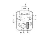
図1は、従来から用いられている、一般的なエキシマレーザ装置の一例を示した図である。なお、エキシマレーザ装置も、放電励起式ガスレーザ装置の一種である。エキシマレーザ装置は、露光装置300の光源として用いられてよく、発生したレーザ光を露光装置300に出力してよい。なお、露光装置300には、露光装置コントローラ301が備えられ、エキシマレーザ装置のレーザコントローラ240と相互に通信を行い、エキシマレーザ装置からのレーザ光の出力命令を行うように構成されてよい。
次に、図1及び図2を参照して、エキシマレーザ装置の動作について説明する。
次に、従来から用いられている一般的なエキシマレーザ装置の課題について説明する。
4.1 レーザコントローラの制御フロー
4.1.1 レーザチャンバ交換時のフロー
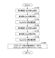
図5は、磁気軸受けを含む本実施形態に係るエキシマレーザ装置のレーザコントローラの制御フローのうち、レーザチャンバ交換時のフローを示した図である。なお、今まで説明した構成要素と同様の構成要素については、同一の参照符号を付し、その説明を省略する。
図6は、磁気軸受けの制御パラメータの再設定を行うべき時期であるか否かを判定するととともに、再設定を行う際にレーザコントローラが行う処理フローを示した図である。
図8は、本実施形態に係るエキシマレーザ装置において、レーザガス圧が変化したときのレーザコントローラが行う処理フローの一例を示した図である。
このように、レーザガス圧の変化に基づいて、磁気軸受けの制御パラメータの再設定を行うようにしてもよい。
図9は、本実施形態に係るエキシマレーザ装置において、レーザチャンバ10の振動が検出されたときのレーザコントローラが行う処理フローの一例を示した図である。
このように、振動センサ131の振動検出に基づいて、磁気軸受けの制御パラメータの再設定を行うようにしてもよい。
図10は、本実施形態に係るエキシマレーザ装置において、レーザ光のエネルギ安定性の値に基づいてレーザコントローラが行う処理フローの一例を示した図である。
図11は、本実施形態に係るエキシマレーザ装置において、レーザ光の波長安定性の値に基づいてレーザコントローラが行う処理フローの一例を示した図である。
図12は、本実施形態に係るエキシマレーザ装置において、磁気軸受けコントローラのエラー出力時にレーザコントローラが行う処理フローの一例を示した図である。
図13は、本実施形態に係るエキシマレーザ装置において、磁気軸受けのタッチダウン時にレーザコントローラが行う処理フローの一例を示した図である。
図14は、図5のステップS140、図6のステップS240、図7のステップS360、図8のステップS540、図9のステップS620、図10のステップS720、図11のステップS820、図12のステップS940及び図13のステップS1040で示した磁気軸受けの制御パラメータの取得及び設定の処理ステップについてより詳細に説明するための第1の処理フローを示した図である。
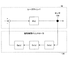
図16は、本実施形態に係るエキシマレーザ装置の磁気軸受け制御系の一例を示した制御ブロック図である。図16において、レーザチャンバ10と軸受けコントローラ130からなるフィードバック制御系のブロック図が示されている。なお、レーザチャンバ10内には、軸90に変位を検出する変位センサ120が新たに設けられているものとする。
6.1 磁気軸受けのセンサの較正
図18は、本実施形態に係るエキシマレーザ装置の磁気軸受けの変位センサの較正方法を説明するための図である。
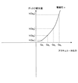
図21は、本実施形態に係るエキシマレーザ装置の磁気軸受けのアクチュエータの較正方法を説明するための図である。
6.3.1 磁気軸受けの制御ゲインの取得と設定
図24は、本実施形態に係るエキシマレーザ装置の磁気軸受けの制御系の一例を示したブロック図である。
図27は、本実施形態に係るエキシマレーザ装置における慣性中心制御の制御パラメータの取得及び設定について説明するための図である。
7.1 アキシャル方向の変位センサの較正とアクチュエータの較正
図31は、アキシャル方向の磁気軸受けの断面構成の一例を示した図である。今まで、ラジアル方向について変位センサ及びアクチュエータを較正する実施形態について説明したが、同様に、アキシャル方向についても、変位センサ及びアクチュエータの較正を行うことが可能である。以下、その内容について説明する。
20、21 電極
80 クロスフローファン
90 軸
100、101 磁気軸受け
150 磁気軸受けコントローラ
240 レーザコントローラ
280 レーザフレーム
Claims (3)
- レーザを発生させるレーザチャンバと、
該レーザチャンバ内に設けられた一対の放電電極と、
前記レーザチャンバ内に設けられ、前記レーザチャンバ内のガスを循環可能に構成された磁気軸受けを備えたファンと、
前記レーザチャンバを収容する筐体と、
前記磁気軸受けに電気的に接続され、前記磁気軸受けを制御可能であるとともに、前記レーザチャンバとは別体として前記筐体内に設けられた磁気軸受けコントローラと、
前記レーザの発生を制御するレーザコントローラと、
を備え、
前記ファンは、ロータを備え、
前記磁気軸受けは、前記ロータを浮上させる磁気浮上アクチュエータと、前記ロータの位置を検出する変位センサとを備え、
前記レーザコントローラは、前記磁気軸受けコントローラに、
前記変位センサ及び前記磁気浮上アクチュエータの較正を行わせるとともに、較正された前記変位センサ及び前記磁気浮上アクチュエータを用いて、前記磁気軸受けの制御に必要な制御パラメータを算出して設定させ、
前記ファンの回転数を制御するモータコントローラが、前記ファンを回転させるモータと前記磁気軸受けコントローラとに接続されている
放電励起式ガスレーザ装置。 - 前記レーザコントローラは、前記レーザチャンバの交換後の設置と、前記磁気軸受けのタッチダウンと、前記磁気軸受けのエラーの少なくとも1つを検出したときに、前記制御パラメータの算出及び設定を前記磁気軸受けコントローラに行わせる
請求項1に記載の放電励起式ガスレーザ装置。 - 前記レーザチャンバは、独立して交換可能であり、
前記レーザコントローラは、前記レーザチャンバの交換後に、所定の時間経過、前記レーザの所定の出力回数、前記レーザチャンバ内の所定のガス圧の所定の変化、前記レーザチャンバの振動、前記レーザの波長安定性の所定の変化、前記レーザのエネルギ安定性の所定の変化、前記磁気軸受けのタッチダウン、及び前記磁気軸受けコントローラのエラー、の少なくとも1つを検出したときに、前記磁気軸受けコントローラに、前記制御パラメータの算出と設定を行わせる
請求項1に記載の放電励起式ガスレーザ装置。
Priority Applications (3)
| Application Number | Priority Date | Filing Date | Title |
|---|---|---|---|
| JP2012227584A JP6063199B2 (ja) | 2012-10-15 | 2012-10-15 | 放電励起式ガスレーザ装置 |
| US14/049,383 US9059554B2 (en) | 2012-10-15 | 2013-10-09 | Discharge-pumped gas laser device |
| US14/531,876 US9225139B2 (en) | 2012-10-15 | 2014-11-03 | Discharge-pumped gas laser device |
Applications Claiming Priority (1)
| Application Number | Priority Date | Filing Date | Title |
|---|---|---|---|
| JP2012227584A JP6063199B2 (ja) | 2012-10-15 | 2012-10-15 | 放電励起式ガスレーザ装置 |
Publications (2)
| Publication Number | Publication Date |
|---|---|
| JP2014082243A JP2014082243A (ja) | 2014-05-08 |
| JP6063199B2 true JP6063199B2 (ja) | 2017-01-18 |
Family
ID=50475296
Family Applications (1)
| Application Number | Title | Priority Date | Filing Date |
|---|---|---|---|
| JP2012227584A Active JP6063199B2 (ja) | 2012-10-15 | 2012-10-15 | 放電励起式ガスレーザ装置 |
Country Status (2)
| Country | Link |
|---|---|
| US (2) | US9059554B2 (ja) |
| JP (1) | JP6063199B2 (ja) |
Families Citing this family (5)
| Publication number | Priority date | Publication date | Assignee | Title |
|---|---|---|---|---|
| WO2016143135A1 (ja) * | 2015-03-12 | 2016-09-15 | ギガフォトン株式会社 | 放電励起式ガスレーザ装置 |
| KR101893870B1 (ko) * | 2015-12-18 | 2018-08-31 | 김창현 | 가스 농도 측정 장치 |
| WO2018105002A1 (ja) * | 2016-12-05 | 2018-06-14 | ギガフォトン株式会社 | レーザ装置 |
| WO2018193528A1 (ja) * | 2017-04-18 | 2018-10-25 | ギガフォトン株式会社 | ガスレーザ装置及び磁気軸受制御方法 |
| JP7428667B2 (ja) * | 2019-02-07 | 2024-02-06 | ギガフォトン株式会社 | 機械学習方法、消耗品管理装置、及びコンピュータ可読媒体 |
Family Cites Families (17)
| Publication number | Priority date | Publication date | Assignee | Title |
|---|---|---|---|---|
| US5848089A (en) | 1997-07-11 | 1998-12-08 | Cymer, Inc. | Excimer laser with magnetic bearings supporting fan |
| US6330261B1 (en) * | 1997-07-18 | 2001-12-11 | Cymer, Inc. | Reliable, modular, production quality narrow-band high rep rate ArF excimer laser |
| DE59914570D1 (de) * | 1998-08-24 | 2008-01-17 | Levitronix Llc | Sensoranordnung in einem elektromagnetischen Drehantrieb |
| JP4033631B2 (ja) * | 1998-11-30 | 2008-01-16 | 株式会社荏原製作所 | 放電励起エキシマレーザ装置 |
| JP2000183436A (ja) * | 1998-12-18 | 2000-06-30 | Komatsu Ltd | エキシマレ―ザ装置 |
| US6490304B1 (en) * | 1999-03-05 | 2002-12-03 | Ntn Corporation | Excimer laser device |
| US6104735A (en) * | 1999-04-13 | 2000-08-15 | Cymer, Inc. | Gas discharge laser with magnetic bearings and magnetic reluctance centering for fan drive assembly |
| JP3766230B2 (ja) * | 1999-04-21 | 2006-04-12 | 株式会社荏原製作所 | エキシマレーザ装置 |
| US6370174B1 (en) * | 1999-10-20 | 2002-04-09 | Cymer, Inc. | Injection seeded F2 lithography laser |
| JP3877912B2 (ja) * | 1999-05-25 | 2007-02-07 | 株式会社荏原製作所 | 放電励起エキシマレーザ装置 |
| US6190319B1 (en) * | 1999-06-21 | 2001-02-20 | International Business Machines Corporation | Self calibrating linear position sensor |
| JP2001077446A (ja) * | 1999-09-07 | 2001-03-23 | Nsk Ltd | エキシマレーザ装置 |
| JP2001352114A (ja) * | 2000-06-08 | 2001-12-21 | Ebara Corp | エキシマレーザ装置用磁気軸受装置 |
| JP2003056489A (ja) * | 2001-08-21 | 2003-02-26 | Ntn Corp | エキシマレーザ装置のガス循環ファン |
| JP2004132441A (ja) * | 2002-10-09 | 2004-04-30 | Ntn Corp | 磁気軸受装置、それを用いたエキシマレーザ用貫流ファン装置、磁気軸受のフィードバック制御をコンピュータに実行させるためのプログラム、および磁気軸受のフィードバック制御をコンピュータに実行させるためのプログラムを記録したコンピュータ読み取り可能な記録媒体 |
| JP4914312B2 (ja) | 2006-08-30 | 2012-04-11 | 株式会社荏原製作所 | 磁気軸受装置 |
| EP1895180A2 (en) | 2006-08-30 | 2008-03-05 | Ebara Corporation | Magnetic bearing device, rotating system therewith and method of identification of the model of the main unit in a rotating system |
-
2012
- 2012-10-15 JP JP2012227584A patent/JP6063199B2/ja active Active
-
2013
- 2013-10-09 US US14/049,383 patent/US9059554B2/en active Active
-
2014
- 2014-11-03 US US14/531,876 patent/US9225139B2/en active Active
Also Published As
| Publication number | Publication date |
|---|---|
| US20150055672A1 (en) | 2015-02-26 |
| US20140105238A1 (en) | 2014-04-17 |
| JP2014082243A (ja) | 2014-05-08 |
| US9059554B2 (en) | 2015-06-16 |
| US9225139B2 (en) | 2015-12-29 |
Similar Documents
| Publication | Publication Date | Title |
|---|---|---|
| JP6063199B2 (ja) | 放電励起式ガスレーザ装置 | |
| US11162530B2 (en) | Gas laser apparatus and magnetic bearing control method | |
| CN110999044B (zh) | 旋转驱动装置、轴流送风器、组装方法、激光振荡装置 | |
| KR20040023785A (ko) | 전원감시장치 및 그 제어방법, 노광장치 | |
| US10250008B2 (en) | Discharge excitation gas laser apparatus | |
| CN108352674B (zh) | 准分子激光装置 | |
| US10148059B2 (en) | Gain mirror for solid state ring laser rotation sensors | |
| JP2004193425A (ja) | 移動制御方法及び装置、露光装置、並びにデバイス製造方法 | |
| JPWO2007066700A1 (ja) | レーザ光源装置、並びに露光方法及び装置 | |
| JP5662120B2 (ja) | 極端紫外光源装置及びチャンバ装置 | |
| US20230387642A1 (en) | Chamber device, gas laser device, and electronic device manufacturing method | |
| WO2010134256A1 (ja) | ガスレーザ発振装置およびガスレーザ加工機 | |
| JPWO2020174582A1 (ja) | 狭帯域化モジュール、ガスレーザ装置、及び電子デバイスの製造方法 | |
| JP5854216B2 (ja) | 遠心分離機 | |
| JP5077271B2 (ja) | レーザ発振装置およびレーザ加工機 | |
| JP4529552B2 (ja) | 磁気軸受式ターボ分子ポンプ | |
| US20230275386A1 (en) | Discharge electrode, method for manufacturing anode, and method for manufacturing electronic devices | |
| JP7333772B2 (ja) | ガスレーザ装置 | |
| JP2011113993A (ja) | ガスレーザ発振装置およびガスレーザ加工機 | |
| JP2005156546A (ja) | 薄板材の測定装置および測定方法 | |
| JP5852216B2 (ja) | 極端紫外光源装置及びチャンバ装置 | |
| JP2006005061A (ja) | 冷却媒体貯蔵用タンク | |
| JPH05102559A (ja) | 狭帯域レ−ザ装置 | |
| JP2000133860A (ja) | 気体循環装置、及びレーザ発振装置 | |
| JP2009270834A (ja) | 試料の形状を測定する測定方法、保持装置、及び形状測定装置 |
Legal Events
| Date | Code | Title | Description |
|---|---|---|---|
| A621 | Written request for application examination |
Free format text: JAPANESE INTERMEDIATE CODE: A621 Effective date: 20150910 |
|
| RD02 | Notification of acceptance of power of attorney |
Free format text: JAPANESE INTERMEDIATE CODE: A7422 Effective date: 20150910 |
|
| A977 | Report on retrieval |
Free format text: JAPANESE INTERMEDIATE CODE: A971007 Effective date: 20160530 |
|
| A131 | Notification of reasons for refusal |
Free format text: JAPANESE INTERMEDIATE CODE: A131 Effective date: 20160607 |
|
| A601 | Written request for extension of time |
Free format text: JAPANESE INTERMEDIATE CODE: A601 Effective date: 20160607 |
|
| A521 | Request for written amendment filed |
Free format text: JAPANESE INTERMEDIATE CODE: A523 Effective date: 20160727 |
|
| RD01 | Notification of change of attorney |
Free format text: JAPANESE INTERMEDIATE CODE: A7421 Effective date: 20160916 |
|
| A521 | Request for written amendment filed |
Free format text: JAPANESE INTERMEDIATE CODE: A821 Effective date: 20160916 |
|
| TRDD | Decision of grant or rejection written | ||
| A01 | Written decision to grant a patent or to grant a registration (utility model) |
Free format text: JAPANESE INTERMEDIATE CODE: A01 Effective date: 20161116 |
|
| A61 | First payment of annual fees (during grant procedure) |
Free format text: JAPANESE INTERMEDIATE CODE: A61 Effective date: 20161216 |
|
| R150 | Certificate of patent or registration of utility model |
Ref document number: 6063199 Country of ref document: JP Free format text: JAPANESE INTERMEDIATE CODE: R150 |
|
| R250 | Receipt of annual fees |
Free format text: JAPANESE INTERMEDIATE CODE: R250 |
|
| R250 | Receipt of annual fees |
Free format text: JAPANESE INTERMEDIATE CODE: R250 |
|
| R250 | Receipt of annual fees |
Free format text: JAPANESE INTERMEDIATE CODE: R250 |
|
| R250 | Receipt of annual fees |
Free format text: JAPANESE INTERMEDIATE CODE: R250 |
|
| R250 | Receipt of annual fees |
Free format text: JAPANESE INTERMEDIATE CODE: R250 |