JP6032393B2 - 整流回路 - Google Patents
整流回路 Download PDFInfo
- Publication number
- JP6032393B2 JP6032393B2 JP2012087718A JP2012087718A JP6032393B2 JP 6032393 B2 JP6032393 B2 JP 6032393B2 JP 2012087718 A JP2012087718 A JP 2012087718A JP 2012087718 A JP2012087718 A JP 2012087718A JP 6032393 B2 JP6032393 B2 JP 6032393B2
- Authority
- JP
- Japan
- Prior art keywords
- diode
- voltage
- circuit
- series
- input
- Prior art date
- Legal status (The legal status is an assumption and is not a legal conclusion. Google has not performed a legal analysis and makes no representation as to the accuracy of the status listed.)
- Active
Links
- 239000003990 capacitor Substances 0.000 claims description 32
- 238000011084 recovery Methods 0.000 claims description 27
- 239000004065 semiconductor Substances 0.000 claims description 21
- 230000002457 bidirectional effect Effects 0.000 claims description 18
- HBMJWWWQQXIZIP-UHFFFAOYSA-N silicon carbide Chemical compound [Si+]#[C-] HBMJWWWQQXIZIP-UHFFFAOYSA-N 0.000 claims description 10
- 229910010271 silicon carbide Inorganic materials 0.000 claims description 10
- 230000004888 barrier function Effects 0.000 claims description 5
- 230000005669 field effect Effects 0.000 claims description 3
- 238000006243 chemical reaction Methods 0.000 description 5
- 230000007423 decrease Effects 0.000 description 4
- 230000000903 blocking effect Effects 0.000 description 3
- 238000010586 diagram Methods 0.000 description 3
- 238000000034 method Methods 0.000 description 3
- 230000003071 parasitic effect Effects 0.000 description 3
- 230000003247 decreasing effect Effects 0.000 description 1
- 230000007613 environmental effect Effects 0.000 description 1
- 230000001360 synchronised effect Effects 0.000 description 1
Images


Classifications
-
- H—ELECTRICITY
- H02—GENERATION; CONVERSION OR DISTRIBUTION OF ELECTRIC POWER
- H02M—APPARATUS FOR CONVERSION BETWEEN AC AND AC, BETWEEN AC AND DC, OR BETWEEN DC AND DC, AND FOR USE WITH MAINS OR SIMILAR POWER SUPPLY SYSTEMS; CONVERSION OF DC OR AC INPUT POWER INTO SURGE OUTPUT POWER; CONTROL OR REGULATION THEREOF
- H02M7/00—Conversion of ac power input into dc power output; Conversion of dc power input into ac power output
- H02M7/02—Conversion of ac power input into dc power output without possibility of reversal
- H02M7/04—Conversion of ac power input into dc power output without possibility of reversal by static converters
- H02M7/12—Conversion of ac power input into dc power output without possibility of reversal by static converters using discharge tubes with control electrode or semiconductor devices with control electrode
- H02M7/21—Conversion of ac power input into dc power output without possibility of reversal by static converters using discharge tubes with control electrode or semiconductor devices with control electrode using devices of a triode or transistor type requiring continuous application of a control signal
- H02M7/217—Conversion of ac power input into dc power output without possibility of reversal by static converters using discharge tubes with control electrode or semiconductor devices with control electrode using devices of a triode or transistor type requiring continuous application of a control signal using semiconductor devices only
-
- H—ELECTRICITY
- H02—GENERATION; CONVERSION OR DISTRIBUTION OF ELECTRIC POWER
- H02M—APPARATUS FOR CONVERSION BETWEEN AC AND AC, BETWEEN AC AND DC, OR BETWEEN DC AND DC, AND FOR USE WITH MAINS OR SIMILAR POWER SUPPLY SYSTEMS; CONVERSION OF DC OR AC INPUT POWER INTO SURGE OUTPUT POWER; CONTROL OR REGULATION THEREOF
- H02M7/00—Conversion of ac power input into dc power output; Conversion of dc power input into ac power output
- H02M7/02—Conversion of ac power input into dc power output without possibility of reversal
- H02M7/04—Conversion of ac power input into dc power output without possibility of reversal by static converters
- H02M7/06—Conversion of ac power input into dc power output without possibility of reversal by static converters using discharge tubes without control electrode or semiconductor devices without control electrode
-
- H—ELECTRICITY
- H02—GENERATION; CONVERSION OR DISTRIBUTION OF ELECTRIC POWER
- H02M—APPARATUS FOR CONVERSION BETWEEN AC AND AC, BETWEEN AC AND DC, OR BETWEEN DC AND DC, AND FOR USE WITH MAINS OR SIMILAR POWER SUPPLY SYSTEMS; CONVERSION OF DC OR AC INPUT POWER INTO SURGE OUTPUT POWER; CONTROL OR REGULATION THEREOF
- H02M7/00—Conversion of ac power input into dc power output; Conversion of dc power input into ac power output
- H02M7/02—Conversion of ac power input into dc power output without possibility of reversal
- H02M7/04—Conversion of ac power input into dc power output without possibility of reversal by static converters
- H02M7/12—Conversion of ac power input into dc power output without possibility of reversal by static converters using discharge tubes with control electrode or semiconductor devices with control electrode
Description
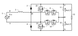
例えば、交流入力電圧Vinが正極性で、かつ電圧関係がVin<Vout/2の場合、双方向半導体スイッチ用MOSFET7〜10のゲートを全てオンすると、ダイオード3と5の接続点U1の電位は直流出力のM点及び交流電源1のV点の電位と等しくなり、U1−V間電圧は0Vとなる。このため、交流電源1→リアクトル2→MOSFET7→MOSFET8→MOSFET10→MOSFET9→交流電源1の経路で電流が流れ、交流電源1の電圧Vinがリアクトル2の両端に印加され、入力電流Iinは増加する。以下、この状態を0電圧モードと称する。
MOSFET7と8が高周波スイッチングを行うとダイオード3と4には高周波電圧が印加され、高周波の電流の導通、遮断を行う。同様に、MOSFET 9と10が高周波スイッチングを行うとダイオード5と6に高周波電圧が印加され、高周波の電流の導通、遮断を行う。特許文献1の図2、図3等には両方の双方向半導体スイッチに高周波スイッチングをさせることが示されている。この高周波動作に耐えるために、ダイオード3〜6には逆回復時間(逆電圧印加時の電流遮断時間)の短い、いわゆるファーストリカバリダイオードが用いられる。一方、ファーストリカバリダイオードは、商用周波数の整流に用いられる、いわゆる一般整流用ダイオードよりも順電圧降下が高くなる傾向にある。
従って、本発明の課題は、交流電圧から3レベルの直流電圧を生成する整流回路として、交流入力電流を正弦波化でき、発生損失が小さく、低価格の整流回路を提供することである。
第3の発明においては、第1〜第2の発明における、前記ファーストリカバリダイオードの代わりに、SiC(炭化珪素)によるショットキーバリアダイオードを用いる。
交流入力電圧Vinが負の場合も同様であり、MOSFET9及び10は交流入力電圧Vinの絶対値のVout/2に対する大小関係で、半サイクルに1回ずつオン、オフ動作を行う。この時はMOSFET9のオフ期間にダイオード20が導通する。
尚、ダイオード3と4もMOSFETに置き換えることが一見可能なように見えるが、実際には導通損失の低いMOSFETは、数百ボルト以上の耐圧のものにおいては寄生ダイオードの逆回復時間が長いなどの理由から、高周波での整流動作に不向きであり、適用は困難である。本発明は整流回路の片側を低周波動作にすることで、数百ボルト耐圧のMOSFETによる整流を可能とした点に特徴がある。
3〜6・・・ファーストリカバリダイオード
7〜10、22、23・・・MOSFET
11、12・・・コンデンサ 13・・・負荷
20、21・・・一般整流用ダイオード
Claims (3)
- 交流入力電圧を直流電圧に変換する、いわゆる整流回路であって、交流電源の一端にリアクトルの一端を接続し、前記リアクトルの他端に、ダイオード直列回路を並列接続してなるダイオードブリッジ回路の交流入力の一方を、交流電源の他端に前記ダイオードブリッジ回路の交流入力の他方を、各々接続し、前記ダイオードブリッジ回路の直流出力の端子間に複数のコンデンサを直列接続したコンデンサ直列回路を接続し、前記コンデンサ直列回路の中間接続点と、前記ダイオードブリッジ回路の交流入力の一方及び他方との間を、単一または複数の半導体素子からなり、順方向と逆方向の双方向の電流の導通、遮断を制御可能な双方向半導体スイッチを介して各々接続して構成された整流回路であり、前記ダイオード直列回路の一方を構成するダイオードは、一般整流用ダイオードに比べて逆回復時間の短い、いわゆるファーストリカバリダイオードとし、他方のダイオード直列回路を構成するダイオードは、ファーストリカバリダイオードに比べて逆回復時間が長く、かつ順電圧降下の小さい、いわゆる一般整流用ダイオードとし、前記一般整流用ダイオードで構成されたダイオード直列回路の直列接続点に接続された双方向半導体スイッチは前記交流入力電圧の周波数で、前記ファーストリカバリダイオードで構成されたダイオード直列回路の直列接続点に接続された双方向半導体スイッチは前記交流入力電圧の周波数より高い周波数で、各々駆動することを特徴とする整流回路。
- 前記一般整流用ダイオードの代わりにMOSFET(絶縁ゲート電界効果形トランジスタ)を用いたことを特徴とする請求項1に記載の整流回路。
- 前記ファーストリカバリダイオードの代わりに、SiC(炭化珪素)によるショットキーバリアダイオードを用いたことを特徴とする請求項1〜2の何れか1項に記載の整流回路。
Priority Applications (4)
| Application Number | Priority Date | Filing Date | Title |
|---|---|---|---|
| JP2012087718A JP6032393B2 (ja) | 2012-04-06 | 2012-04-06 | 整流回路 |
| PCT/JP2012/006765 WO2013150573A1 (ja) | 2012-04-06 | 2012-10-23 | 整流回路 |
| CN201280071145.XA CN104205602B (zh) | 2012-04-06 | 2012-10-23 | 整流电路 |
| US14/476,047 US9385624B2 (en) | 2012-04-06 | 2014-09-03 | Rectifier circuit |
Applications Claiming Priority (1)
| Application Number | Priority Date | Filing Date | Title |
|---|---|---|---|
| JP2012087718A JP6032393B2 (ja) | 2012-04-06 | 2012-04-06 | 整流回路 |
Publications (2)
| Publication Number | Publication Date |
|---|---|
| JP2013219903A JP2013219903A (ja) | 2013-10-24 |
| JP6032393B2 true JP6032393B2 (ja) | 2016-11-30 |
Family
ID=49300104
Family Applications (1)
| Application Number | Title | Priority Date | Filing Date |
|---|---|---|---|
| JP2012087718A Active JP6032393B2 (ja) | 2012-04-06 | 2012-04-06 | 整流回路 |
Country Status (4)
| Country | Link |
|---|---|
| US (1) | US9385624B2 (ja) |
| JP (1) | JP6032393B2 (ja) |
| CN (1) | CN104205602B (ja) |
| WO (1) | WO2013150573A1 (ja) |
Families Citing this family (12)
| Publication number | Priority date | Publication date | Assignee | Title |
|---|---|---|---|---|
| WO2015069917A1 (en) * | 2013-11-07 | 2015-05-14 | Rompower Energy System, Inc. | Bridgeless pfc using single sided high frequency switching |
| CN104601002B (zh) * | 2014-12-29 | 2017-06-30 | 南京航空航天大学 | 一种稀疏式双级矩阵变换器拓扑结构 |
| JP6551041B2 (ja) * | 2015-08-19 | 2019-07-31 | 富士電機株式会社 | 交流−直流変換装置 |
| JP6959400B2 (ja) * | 2015-09-10 | 2021-11-02 | 日立ジョンソンコントロールズ空調株式会社 | 直流電源装置および空気調和機 |
| JP6712104B2 (ja) * | 2015-09-10 | 2020-06-17 | 日立ジョンソンコントロールズ空調株式会社 | 直流電源装置および空気調和機 |
| JP6798802B2 (ja) * | 2016-06-28 | 2020-12-09 | 日立ジョンソンコントロールズ空調株式会社 | 直流電源装置および空気調和機 |
| JP6955077B2 (ja) * | 2016-06-28 | 2021-10-27 | 日立ジョンソンコントロールズ空調株式会社 | 直流電源装置および空気調和機 |
| JP6254301B1 (ja) * | 2016-09-02 | 2017-12-27 | 新電元工業株式会社 | Mosfet及び電力変換回路 |
| FR3058593B1 (fr) * | 2016-11-10 | 2018-11-09 | Renault S.A.S | Procede de commande d'un redresseur triphase pour un dispositif de charge embarque sur un vehicule electrique ou hybride. |
| KR102455073B1 (ko) * | 2018-02-23 | 2022-10-14 | 엘지전자 주식회사 | 직류 링크 전압의 조절이 가능한 정류 장치 |
| JP7039430B2 (ja) * | 2018-09-19 | 2022-03-22 | 株式会社東芝 | Ac/dcコンバータ |
| EP3930159B1 (en) * | 2020-06-26 | 2023-05-17 | Siemens Aktiengesellschaft | Active rectifier circuit |
Family Cites Families (17)
| Publication number | Priority date | Publication date | Assignee | Title |
|---|---|---|---|---|
| US5477131A (en) * | 1993-09-02 | 1995-12-19 | Motorola, Inc. | Zero-voltage-transition switching power converters using magnetic feedback |
| JPH08196077A (ja) * | 1994-11-18 | 1996-07-30 | Toshiba Corp | 電力変換装置及びこれを利用した空気調和装置 |
| JP3225825B2 (ja) * | 1996-01-12 | 2001-11-05 | 富士電機株式会社 | Ac/dc変換装置 |
| JP3230434B2 (ja) * | 1996-06-05 | 2001-11-19 | 富士電機株式会社 | Ac/dc変換回路 |
| US6320772B1 (en) * | 1999-05-26 | 2001-11-20 | Matsushita Electric Industrial Co., Ltd. | Converter circuit having control means with capability to short-circuit converter output |
| JP3934982B2 (ja) * | 2001-04-17 | 2007-06-20 | 松下電器産業株式会社 | 電源装置 |
| KR100418127B1 (ko) * | 2001-04-17 | 2004-02-11 | 마츠시타 덴끼 산교 가부시키가이샤 | 전원장치 |
| GB0321321D0 (en) * | 2003-09-11 | 2003-10-15 | Boc Group Plc | Power factor correction circuit |
| JP2008022625A (ja) * | 2006-07-12 | 2008-01-31 | Fuji Electric Systems Co Ltd | 交流−直流変換装置 |
| BRPI0715762A2 (pt) * | 2006-08-23 | 2013-09-24 | Neumayer Tekfor Holding Gmbh | disposiÇço de conexço entre um munhço do eixo e uma parte de articulaÇço |
| US8489136B2 (en) * | 2007-01-05 | 2013-07-16 | Aliphcom | Wireless link to transmit digital audio data between devices in a manner controlled dynamically to adapt to variable wireless error rates |
| US8498136B2 (en) * | 2007-08-29 | 2013-07-30 | Mitsubishi Electric Corporation | AC-DC converter and compressor driving apparatus and air conditioning apparatus using the same |
| JP2009095083A (ja) * | 2007-10-04 | 2009-04-30 | Fuji Electric Systems Co Ltd | 電力変換装置 |
| JP5274579B2 (ja) | 2008-12-01 | 2013-08-28 | 三菱電機株式会社 | 交流直流変換装置、電動機駆動装置 |
| JP5418893B2 (ja) * | 2009-07-13 | 2014-02-19 | 富士電機株式会社 | 電力変換装置 |
| JP5471291B2 (ja) * | 2009-10-23 | 2014-04-16 | パナソニック株式会社 | 直流電源装置 |
| WO2011048818A1 (ja) * | 2009-10-23 | 2011-04-28 | パナソニック株式会社 | 直流電源装置およびこれを用いた電動機駆動用インバータ装置 |
-
2012
- 2012-04-06 JP JP2012087718A patent/JP6032393B2/ja active Active
- 2012-10-23 WO PCT/JP2012/006765 patent/WO2013150573A1/ja active Application Filing
- 2012-10-23 CN CN201280071145.XA patent/CN104205602B/zh not_active Expired - Fee Related
-
2014
- 2014-09-03 US US14/476,047 patent/US9385624B2/en not_active Expired - Fee Related
Also Published As
| Publication number | Publication date |
|---|---|
| US20140369100A1 (en) | 2014-12-18 |
| CN104205602A (zh) | 2014-12-10 |
| WO2013150573A1 (ja) | 2013-10-10 |
| US9385624B2 (en) | 2016-07-05 |
| JP2013219903A (ja) | 2013-10-24 |
| CN104205602B (zh) | 2016-12-28 |
Similar Documents
| Publication | Publication Date | Title |
|---|---|---|
| JP6032393B2 (ja) | 整流回路 | |
| JP5995139B2 (ja) | 双方向dc/dcコンバータ | |
| JP6191965B2 (ja) | 電力変換装置、およびそれを用いたパワーコンディショナ | |
| JP6454936B2 (ja) | 電力変換装置、およびそれを用いたパワーコンディショナ | |
| AU2014245740B2 (en) | Inverter device | |
| WO2012067167A1 (ja) | 交流-交流変換装置 | |
| JP5228886B2 (ja) | スナバ回路 | |
| JP2015033217A (ja) | 半導体装置、および電力変換装置 | |
| JP2015233406A (ja) | バイパス運転機能を有する直列型h−ブリッジインバータ | |
| JP5362657B2 (ja) | 電力変換装置 | |
| WO2013171800A1 (ja) | 電力変換装置 | |
| JP2012191761A (ja) | 交流−直流変換回路 | |
| JP6012008B2 (ja) | スイッチング回路 | |
| JPWO2013136623A1 (ja) | 電力変換器及びその制御装置 | |
| CN108432110B (zh) | Dc/dc转换器 | |
| JP6455793B2 (ja) | 電力変換装置、及びそれを用いたパワーコンディショナ | |
| JP7024784B2 (ja) | 交直変換回路及び力率改善回路 | |
| JP5930978B2 (ja) | Dc/dcコンバータ | |
| JP2012239292A (ja) | 整流器のスナバ回路 | |
| JP2012010507A (ja) | 直流電源装置 | |
| JP6447944B2 (ja) | 電力変換装置、及びそれを用いたパワーコンディショナ | |
| JP2016046935A (ja) | 半導体装置並びにそれを用いたコンバータ、インバータ、エアーコンディショナー、ソーラーパワーコントローラ、及び自動車 | |
| JP5980009B2 (ja) | スイッチング電源装置 | |
| JP6551041B2 (ja) | 交流−直流変換装置 | |
| JP5879705B2 (ja) | 電力変換装置 |
Legal Events
| Date | Code | Title | Description |
|---|---|---|---|
| A621 | Written request for application examination |
Free format text: JAPANESE INTERMEDIATE CODE: A621 Effective date: 20150316 |
|
| RD02 | Notification of acceptance of power of attorney |
Free format text: JAPANESE INTERMEDIATE CODE: A7422 Effective date: 20151005 |
|
| RD04 | Notification of resignation of power of attorney |
Free format text: JAPANESE INTERMEDIATE CODE: A7424 Effective date: 20151005 |
|
| A131 | Notification of reasons for refusal |
Free format text: JAPANESE INTERMEDIATE CODE: A131 Effective date: 20160322 |
|
| A521 | Request for written amendment filed |
Free format text: JAPANESE INTERMEDIATE CODE: A523 Effective date: 20160519 |
|
| TRDD | Decision of grant or rejection written | ||
| A01 | Written decision to grant a patent or to grant a registration (utility model) |
Free format text: JAPANESE INTERMEDIATE CODE: A01 Effective date: 20160928 |
|
| A61 | First payment of annual fees (during grant procedure) |
Free format text: JAPANESE INTERMEDIATE CODE: A61 Effective date: 20161011 |
|
| R150 | Certificate of patent or registration of utility model |
Ref document number: 6032393 Country of ref document: JP Free format text: JAPANESE INTERMEDIATE CODE: R150 |
|
| R250 | Receipt of annual fees |
Free format text: JAPANESE INTERMEDIATE CODE: R250 |
|
| R250 | Receipt of annual fees |
Free format text: JAPANESE INTERMEDIATE CODE: R250 |
|
| R250 | Receipt of annual fees |
Free format text: JAPANESE INTERMEDIATE CODE: R250 |
|
| R250 | Receipt of annual fees |
Free format text: JAPANESE INTERMEDIATE CODE: R250 |
|
| R250 | Receipt of annual fees |
Free format text: JAPANESE INTERMEDIATE CODE: R250 |