JP5805218B2 - Footwear with sensor system - Google Patents
Footwear with sensor system Download PDFInfo
- Publication number
- JP5805218B2 JP5805218B2 JP2013554651A JP2013554651A JP5805218B2 JP 5805218 B2 JP5805218 B2 JP 5805218B2 JP 2013554651 A JP2013554651 A JP 2013554651A JP 2013554651 A JP2013554651 A JP 2013554651A JP 5805218 B2 JP5805218 B2 JP 5805218B2
- Authority
- JP
- Japan
- Prior art keywords
- insert
- sensor
- force sensing
- lobe
- port
- Prior art date
- Legal status (The legal status is an assumption and is not a legal conclusion. Google has not performed a legal analysis and makes no representation as to the accuracy of the status listed.)
- Active
Links
- 210000002683 foot Anatomy 0.000 claims description 149
- 239000000463 material Substances 0.000 claims description 136
- 238000004891 communication Methods 0.000 claims description 73
- 239000011540 sensing material Substances 0.000 claims description 48
- 230000002093 peripheral effect Effects 0.000 claims description 30
- 210000001872 metatarsal bone Anatomy 0.000 claims description 19
- 238000013461 design Methods 0.000 claims description 12
- 229920005570 flexible polymer Polymers 0.000 claims description 7
- 210000000988 bone and bone Anatomy 0.000 claims 1
- 239000011853 conductive carbon based material Substances 0.000 claims 1
- 239000010410 layer Substances 0.000 description 84
- 238000000034 method Methods 0.000 description 35
- 230000005540 biological transmission Effects 0.000 description 18
- 230000000694 effects Effects 0.000 description 18
- 238000005259 measurement Methods 0.000 description 18
- 210000003811 finger Anatomy 0.000 description 17
- 230000006870 function Effects 0.000 description 17
- 230000006399 behavior Effects 0.000 description 16
- OKTJSMMVPCPJKN-UHFFFAOYSA-N Carbon Chemical compound [C] OKTJSMMVPCPJKN-UHFFFAOYSA-N 0.000 description 15
- 230000008859 change Effects 0.000 description 15
- 230000033001 locomotion Effects 0.000 description 15
- 229910052799 carbon Inorganic materials 0.000 description 14
- 230000015654 memory Effects 0.000 description 13
- 230000000712 assembly Effects 0.000 description 12
- 238000000429 assembly Methods 0.000 description 12
- 239000002131 composite material Substances 0.000 description 12
- 238000012545 processing Methods 0.000 description 12
- 230000006835 compression Effects 0.000 description 11
- 238000007906 compression Methods 0.000 description 11
- 239000004020 conductor Substances 0.000 description 11
- 239000006260 foam Substances 0.000 description 11
- 238000003860 storage Methods 0.000 description 11
- 210000003371 toe Anatomy 0.000 description 11
- 230000000295 complement effect Effects 0.000 description 10
- 239000002184 metal Substances 0.000 description 10
- 229910052751 metal Inorganic materials 0.000 description 10
- 229920000642 polymer Polymers 0.000 description 9
- 238000012546 transfer Methods 0.000 description 9
- 238000003780 insertion Methods 0.000 description 8
- 230000037431 insertion Effects 0.000 description 8
- 238000012544 monitoring process Methods 0.000 description 8
- 230000004913 activation Effects 0.000 description 7
- 238000004422 calculation algorithm Methods 0.000 description 7
- 238000004590 computer program Methods 0.000 description 7
- 238000010586 diagram Methods 0.000 description 7
- 239000004744 fabric Substances 0.000 description 7
- 230000008901 benefit Effects 0.000 description 6
- 229920001971 elastomer Polymers 0.000 description 6
- 210000004744 fore-foot Anatomy 0.000 description 6
- 239000002245 particle Substances 0.000 description 6
- 239000005060 rubber Substances 0.000 description 6
- 230000005641 tunneling Effects 0.000 description 6
- 230000000386 athletic effect Effects 0.000 description 5
- 230000037147 athletic performance Effects 0.000 description 5
- 239000006229 carbon black Substances 0.000 description 5
- 238000009826 distribution Methods 0.000 description 5
- 238000004519 manufacturing process Methods 0.000 description 5
- 239000007769 metal material Substances 0.000 description 5
- 230000008569 process Effects 0.000 description 5
- 238000006243 chemical reaction Methods 0.000 description 4
- 238000005516 engineering process Methods 0.000 description 4
- 239000000835 fiber Substances 0.000 description 4
- 210000000452 mid-foot Anatomy 0.000 description 4
- 210000003813 thumb Anatomy 0.000 description 4
- 238000003466 welding Methods 0.000 description 4
- 230000009471 action Effects 0.000 description 3
- 239000000853 adhesive Substances 0.000 description 3
- 230000001070 adhesive effect Effects 0.000 description 3
- 238000005452 bending Methods 0.000 description 3
- 230000001276 controlling effect Effects 0.000 description 3
- 238000005520 cutting process Methods 0.000 description 3
- 238000013016 damping Methods 0.000 description 3
- 238000013480 data collection Methods 0.000 description 3
- 230000007423 decrease Effects 0.000 description 3
- 239000006261 foam material Substances 0.000 description 3
- 238000010348 incorporation Methods 0.000 description 3
- WABPQHHGFIMREM-UHFFFAOYSA-N lead(0) Chemical compound [Pb] WABPQHHGFIMREM-UHFFFAOYSA-N 0.000 description 3
- 238000007639 printing Methods 0.000 description 3
- 238000007789 sealing Methods 0.000 description 3
- 239000004065 semiconductor Substances 0.000 description 3
- 230000035807 sensation Effects 0.000 description 3
- 238000012549 training Methods 0.000 description 3
- 229920002799 BoPET Polymers 0.000 description 2
- 239000005041 Mylar™ Substances 0.000 description 2
- -1 carbon black) Chemical compound 0.000 description 2
- 229920001940 conductive polymer Polymers 0.000 description 2
- 238000001514 detection method Methods 0.000 description 2
- 229910002804 graphite Inorganic materials 0.000 description 2
- 239000010439 graphite Substances 0.000 description 2
- 230000006872 improvement Effects 0.000 description 2
- 230000007794 irritation Effects 0.000 description 2
- 230000009191 jumping Effects 0.000 description 2
- 239000010985 leather Substances 0.000 description 2
- 239000007788 liquid Substances 0.000 description 2
- 239000011159 matrix material Substances 0.000 description 2
- 239000002103 nanocoating Substances 0.000 description 2
- 230000003287 optical effect Effects 0.000 description 2
- 230000010287 polarization Effects 0.000 description 2
- 239000002861 polymer material Substances 0.000 description 2
- 229920002635 polyurethane Polymers 0.000 description 2
- 239000004814 polyurethane Substances 0.000 description 2
- 230000035945 sensitivity Effects 0.000 description 2
- 229910052709 silver Inorganic materials 0.000 description 2
- 239000004332 silver Substances 0.000 description 2
- 229920002994 synthetic fiber Polymers 0.000 description 2
- 210000002105 tongue Anatomy 0.000 description 2
- XUIMIQQOPSSXEZ-UHFFFAOYSA-N Silicon Chemical compound [Si] XUIMIQQOPSSXEZ-UHFFFAOYSA-N 0.000 description 1
- 206010041349 Somnolence Diseases 0.000 description 1
- 238000010521 absorption reaction Methods 0.000 description 1
- 230000001133 acceleration Effects 0.000 description 1
- 230000003213 activating effect Effects 0.000 description 1
- 239000000654 additive Substances 0.000 description 1
- 238000004026 adhesive bonding Methods 0.000 description 1
- 210000003423 ankle Anatomy 0.000 description 1
- 238000003491 array Methods 0.000 description 1
- 230000036772 blood pressure Effects 0.000 description 1
- 230000036760 body temperature Effects 0.000 description 1
- 238000005219 brazing Methods 0.000 description 1
- 238000004364 calculation method Methods 0.000 description 1
- 239000003575 carbonaceous material Substances 0.000 description 1
- 239000000919 ceramic Substances 0.000 description 1
- 230000002596 correlated effect Effects 0.000 description 1
- 238000007405 data analysis Methods 0.000 description 1
- 238000013500 data storage Methods 0.000 description 1
- 238000011161 development Methods 0.000 description 1
- 238000006073 displacement reaction Methods 0.000 description 1
- BFMKFCLXZSUVPI-UHFFFAOYSA-N ethyl but-3-enoate Chemical compound CCOC(=O)CC=C BFMKFCLXZSUVPI-UHFFFAOYSA-N 0.000 description 1
- 230000001747 exhibiting effect Effects 0.000 description 1
- 230000001939 inductive effect Effects 0.000 description 1
- 230000003993 interaction Effects 0.000 description 1
- 230000001788 irregular Effects 0.000 description 1
- 238000009940 knitting Methods 0.000 description 1
- 239000002649 leather substitute Substances 0.000 description 1
- 230000007257 malfunction Effects 0.000 description 1
- 230000007246 mechanism Effects 0.000 description 1
- 239000012528 membrane Substances 0.000 description 1
- 230000005055 memory storage Effects 0.000 description 1
- 239000002923 metal particle Substances 0.000 description 1
- 150000002739 metals Chemical class 0.000 description 1
- 238000012986 modification Methods 0.000 description 1
- 230000004048 modification Effects 0.000 description 1
- 239000013307 optical fiber Substances 0.000 description 1
- 230000000803 paradoxical effect Effects 0.000 description 1
- 239000011241 protective layer Substances 0.000 description 1
- 230000001105 regulatory effect Effects 0.000 description 1
- 238000010008 shearing Methods 0.000 description 1
- 230000035939 shock Effects 0.000 description 1
- 229910052710 silicon Inorganic materials 0.000 description 1
- 239000010703 silicon Substances 0.000 description 1
- 239000002520 smart material Substances 0.000 description 1
- 238000005476 soldering Methods 0.000 description 1
- 239000012209 synthetic fiber Substances 0.000 description 1
- 230000036962 time dependent Effects 0.000 description 1
- 238000009423 ventilation Methods 0.000 description 1
- 238000013022 venting Methods 0.000 description 1
- 239000011800 void material Substances 0.000 description 1
- 238000009941 weaving Methods 0.000 description 1
Images


Classifications
-
- A—HUMAN NECESSITIES
- A61—MEDICAL OR VETERINARY SCIENCE; HYGIENE
- A61B—DIAGNOSIS; SURGERY; IDENTIFICATION
- A61B5/00—Measuring for diagnostic purposes; Identification of persons
- A61B5/103—Detecting, measuring or recording devices for testing the shape, pattern, colour, size or movement of the body or parts thereof, for diagnostic purposes
- A61B5/1036—Measuring load distribution, e.g. podologic studies
- A61B5/1038—Measuring plantar pressure during gait
-
- A—HUMAN NECESSITIES
- A43—FOOTWEAR
- A43B—CHARACTERISTIC FEATURES OF FOOTWEAR; PARTS OF FOOTWEAR
- A43B3/00—Footwear characterised by the shape or the use
- A43B3/34—Footwear characterised by the shape or the use with electrical or electronic arrangements
-
- A—HUMAN NECESSITIES
- A43—FOOTWEAR
- A43B—CHARACTERISTIC FEATURES OF FOOTWEAR; PARTS OF FOOTWEAR
- A43B13/00—Soles; Sole-and-heel integral units
- A43B13/38—Built-in insoles joined to uppers during the manufacturing process, e.g. structural insoles; Insoles glued to shoes during the manufacturing process
-
- A—HUMAN NECESSITIES
- A43—FOOTWEAR
- A43B—CHARACTERISTIC FEATURES OF FOOTWEAR; PARTS OF FOOTWEAR
- A43B17/00—Insoles for insertion, e.g. footbeds or inlays, for attachment to the shoe after the upper has been joined
- A43B17/003—Insoles for insertion, e.g. footbeds or inlays, for attachment to the shoe after the upper has been joined characterised by the material
- A43B17/006—Insoles for insertion, e.g. footbeds or inlays, for attachment to the shoe after the upper has been joined characterised by the material multilayered
-
- A—HUMAN NECESSITIES
- A43—FOOTWEAR
- A43B—CHARACTERISTIC FEATURES OF FOOTWEAR; PARTS OF FOOTWEAR
- A43B3/00—Footwear characterised by the shape or the use
-
- A—HUMAN NECESSITIES
- A43—FOOTWEAR
- A43B—CHARACTERISTIC FEATURES OF FOOTWEAR; PARTS OF FOOTWEAR
- A43B3/00—Footwear characterised by the shape or the use
- A43B3/34—Footwear characterised by the shape or the use with electrical or electronic arrangements
- A43B3/44—Footwear characterised by the shape or the use with electrical or electronic arrangements with sensors, e.g. for detecting contact or position
-
- A—HUMAN NECESSITIES
- A61—MEDICAL OR VETERINARY SCIENCE; HYGIENE
- A61B—DIAGNOSIS; SURGERY; IDENTIFICATION
- A61B5/00—Measuring for diagnostic purposes; Identification of persons
- A61B5/103—Detecting, measuring or recording devices for testing the shape, pattern, colour, size or movement of the body or parts thereof, for diagnostic purposes
- A61B5/11—Measuring movement of the entire body or parts thereof, e.g. head or hand tremor, mobility of a limb
-
- A—HUMAN NECESSITIES
- A61—MEDICAL OR VETERINARY SCIENCE; HYGIENE
- A61B—DIAGNOSIS; SURGERY; IDENTIFICATION
- A61B5/00—Measuring for diagnostic purposes; Identification of persons
- A61B5/68—Arrangements of detecting, measuring or recording means, e.g. sensors, in relation to patient
- A61B5/6801—Arrangements of detecting, measuring or recording means, e.g. sensors, in relation to patient specially adapted to be attached to or worn on the body surface
- A61B5/6802—Sensor mounted on worn items
- A61B5/6804—Garments; Clothes
- A61B5/6807—Footwear
-
- A—HUMAN NECESSITIES
- A63—SPORTS; GAMES; AMUSEMENTS
- A63B—APPARATUS FOR PHYSICAL TRAINING, GYMNASTICS, SWIMMING, CLIMBING, OR FENCING; BALL GAMES; TRAINING EQUIPMENT
- A63B69/00—Training appliances or apparatus for special sports
-
- G—PHYSICS
- G01—MEASURING; TESTING
- G01C—MEASURING DISTANCES, LEVELS OR BEARINGS; SURVEYING; NAVIGATION; GYROSCOPIC INSTRUMENTS; PHOTOGRAMMETRY OR VIDEOGRAMMETRY
- G01C22/00—Measuring distance traversed on the ground by vehicles, persons, animals or other moving solid bodies, e.g. using odometers, using pedometers
- G01C22/006—Pedometers
-
- G—PHYSICS
- G01—MEASURING; TESTING
- G01L—MEASURING FORCE, STRESS, TORQUE, WORK, MECHANICAL POWER, MECHANICAL EFFICIENCY, OR FLUID PRESSURE
- G01L1/00—Measuring force or stress, in general
- G01L1/26—Auxiliary measures taken, or devices used, in connection with the measurement of force, e.g. for preventing influence of transverse components of force, for preventing overload
-
- G—PHYSICS
- G06—COMPUTING; CALCULATING OR COUNTING
- G06F—ELECTRIC DIGITAL DATA PROCESSING
- G06F3/00—Input arrangements for transferring data to be processed into a form capable of being handled by the computer; Output arrangements for transferring data from processing unit to output unit, e.g. interface arrangements
- G06F3/01—Input arrangements or combined input and output arrangements for interaction between user and computer
- G06F3/03—Arrangements for converting the position or the displacement of a member into a coded form
- G06F3/033—Pointing devices displaced or positioned by the user, e.g. mice, trackballs, pens or joysticks; Accessories therefor
- G06F3/0334—Foot operated pointing devices
-
- A—HUMAN NECESSITIES
- A61—MEDICAL OR VETERINARY SCIENCE; HYGIENE
- A61B—DIAGNOSIS; SURGERY; IDENTIFICATION
- A61B2562/00—Details of sensors; Constructional details of sensor housings or probes; Accessories for sensors
- A61B2562/02—Details of sensors specially adapted for in-vivo measurements
- A61B2562/0252—Load cells
-
- A—HUMAN NECESSITIES
- A61—MEDICAL OR VETERINARY SCIENCE; HYGIENE
- A61B—DIAGNOSIS; SURGERY; IDENTIFICATION
- A61B2562/00—Details of sensors; Constructional details of sensor housings or probes; Accessories for sensors
- A61B2562/02—Details of sensors specially adapted for in-vivo measurements
- A61B2562/0261—Strain gauges
- A61B2562/0266—Optical strain gauges
-
- A—HUMAN NECESSITIES
- A61—MEDICAL OR VETERINARY SCIENCE; HYGIENE
- A61B—DIAGNOSIS; SURGERY; IDENTIFICATION
- A61B2562/00—Details of sensors; Constructional details of sensor housings or probes; Accessories for sensors
- A61B2562/04—Arrangements of multiple sensors of the same type
- A61B2562/046—Arrangements of multiple sensors of the same type in a matrix array
-
- A—HUMAN NECESSITIES
- A61—MEDICAL OR VETERINARY SCIENCE; HYGIENE
- A61B—DIAGNOSIS; SURGERY; IDENTIFICATION
- A61B5/00—Measuring for diagnostic purposes; Identification of persons
- A61B5/103—Detecting, measuring or recording devices for testing the shape, pattern, colour, size or movement of the body or parts thereof, for diagnostic purposes
- A61B5/1036—Measuring load distribution, e.g. podologic studies
-
- A—HUMAN NECESSITIES
- A63—SPORTS; GAMES; AMUSEMENTS
- A63B—APPARATUS FOR PHYSICAL TRAINING, GYMNASTICS, SWIMMING, CLIMBING, OR FENCING; BALL GAMES; TRAINING EQUIPMENT
- A63B2220/00—Measuring of physical parameters relating to sporting activity
-
- A—HUMAN NECESSITIES
- A63—SPORTS; GAMES; AMUSEMENTS
- A63B—APPARATUS FOR PHYSICAL TRAINING, GYMNASTICS, SWIMMING, CLIMBING, OR FENCING; BALL GAMES; TRAINING EQUIPMENT
- A63B2220/00—Measuring of physical parameters relating to sporting activity
- A63B2220/50—Force related parameters
- A63B2220/51—Force
-
- A—HUMAN NECESSITIES
- A63—SPORTS; GAMES; AMUSEMENTS
- A63B—APPARATUS FOR PHYSICAL TRAINING, GYMNASTICS, SWIMMING, CLIMBING, OR FENCING; BALL GAMES; TRAINING EQUIPMENT
- A63B2220/00—Measuring of physical parameters relating to sporting activity
- A63B2220/80—Special sensors, transducers or devices therefor
- A63B2220/83—Special sensors, transducers or devices therefor characterised by the position of the sensor
- A63B2220/836—Sensors arranged on the body of the user
-
- A—HUMAN NECESSITIES
- A63—SPORTS; GAMES; AMUSEMENTS
- A63F—CARD, BOARD, OR ROULETTE GAMES; INDOOR GAMES USING SMALL MOVING PLAYING BODIES; VIDEO GAMES; GAMES NOT OTHERWISE PROVIDED FOR
- A63F2300/00—Features of games using an electronically generated display having two or more dimensions, e.g. on a television screen, showing representations related to the game
- A63F2300/10—Features of games using an electronically generated display having two or more dimensions, e.g. on a television screen, showing representations related to the game characterized by input arrangements for converting player-generated signals into game device control signals
- A63F2300/1012—Features of games using an electronically generated display having two or more dimensions, e.g. on a television screen, showing representations related to the game characterized by input arrangements for converting player-generated signals into game device control signals involving biosensors worn by the player, e.g. for measuring heart beat, limb activity
-
- A—HUMAN NECESSITIES
- A63—SPORTS; GAMES; AMUSEMENTS
- A63F—CARD, BOARD, OR ROULETTE GAMES; INDOOR GAMES USING SMALL MOVING PLAYING BODIES; VIDEO GAMES; GAMES NOT OTHERWISE PROVIDED FOR
- A63F2300/00—Features of games using an electronically generated display having two or more dimensions, e.g. on a television screen, showing representations related to the game
- A63F2300/10—Features of games using an electronically generated display having two or more dimensions, e.g. on a television screen, showing representations related to the game characterized by input arrangements for converting player-generated signals into game device control signals
- A63F2300/1025—Features of games using an electronically generated display having two or more dimensions, e.g. on a television screen, showing representations related to the game characterized by input arrangements for converting player-generated signals into game device control signals details of the interface with the game device, e.g. USB version detection
- A63F2300/1031—Features of games using an electronically generated display having two or more dimensions, e.g. on a television screen, showing representations related to the game characterized by input arrangements for converting player-generated signals into game device control signals details of the interface with the game device, e.g. USB version detection using a wireless connection, e.g. Bluetooth, infrared connections
-
- F—MECHANICAL ENGINEERING; LIGHTING; HEATING; WEAPONS; BLASTING
- F04—POSITIVE - DISPLACEMENT MACHINES FOR LIQUIDS; PUMPS FOR LIQUIDS OR ELASTIC FLUIDS
- F04C—ROTARY-PISTON, OR OSCILLATING-PISTON, POSITIVE-DISPLACEMENT MACHINES FOR LIQUIDS; ROTARY-PISTON, OR OSCILLATING-PISTON, POSITIVE-DISPLACEMENT PUMPS
- F04C2270/00—Control; Monitoring or safety arrangements
- F04C2270/04—Force
- F04C2270/041—Controlled or regulated
Landscapes
- Health & Medical Sciences (AREA)
- Life Sciences & Earth Sciences (AREA)
- Engineering & Computer Science (AREA)
- Physics & Mathematics (AREA)
- General Health & Medical Sciences (AREA)
- Animal Behavior & Ethology (AREA)
- Molecular Biology (AREA)
- Biophysics (AREA)
- Pathology (AREA)
- Biomedical Technology (AREA)
- Heart & Thoracic Surgery (AREA)
- Medical Informatics (AREA)
- Veterinary Medicine (AREA)
- Surgery (AREA)
- Public Health (AREA)
- General Physics & Mathematics (AREA)
- Dentistry (AREA)
- Oral & Maxillofacial Surgery (AREA)
- General Engineering & Computer Science (AREA)
- Theoretical Computer Science (AREA)
- Microelectronics & Electronic Packaging (AREA)
- Human Computer Interaction (AREA)
- Remote Sensing (AREA)
- Radar, Positioning & Navigation (AREA)
- Physiology (AREA)
- Chemical & Material Sciences (AREA)
- Materials Engineering (AREA)
- Wood Science & Technology (AREA)
- Physical Education & Sports Medicine (AREA)
- Footwear And Its Accessory, Manufacturing Method And Apparatuses (AREA)
Description
本出願は、米国仮出願番号61/443,911(2011年2月17日提出)に対する優先権およびその利益を主張するもので、その全体を参照することにより本書に組込む。 This application claims priority and benefit to US Provisional Application No. 61 / 443,911 (filed February 17, 2011), which is incorporated herein by reference in its entirety.
本発明は、一般に、センサーシステムを持つ履物に関連し、より具体的には、靴内に位置する通信ポートに動作可能に接続された力センサー組立品を持つ靴に関連する。 The present invention relates generally to footwear having a sensor system, and more particularly to a shoe having a force sensor assembly operably connected to a communication port located within the shoe.
その内部にセンサーシステムが組み込まれた靴が知られている。センサーシステムは、パフォーマンスデータを収集し、そのデータは分析目的などで後に使用するためにアクセスできる。あるシステムにおいて、センサーシステムは、複雑であるか、またはデータは特定のオペレーティングシステムでのみアクセスまたは使用が可能である。こうして、収集したデータの用途が不必要に限定されうる。したがって、センサーシステムを持つ靴は多数の有利な特徴を提供する一方、それにもかかわらず、ある一定の制限を持つ。本発明は、従来の技術のこれらの制限およびその他の欠点を克服し、これまでに利用できなかった新しい特徴を提供することを模索する。 Shoes with a sensor system built into them are known. The sensor system collects performance data that can be accessed for later use, such as for analytical purposes. In some systems, the sensor system is complex or the data can only be accessed or used with a specific operating system. In this way, the use of the collected data can be unnecessarily limited. Thus, a shoe with a sensor system provides a number of advantageous features, but nevertheless has certain limitations. The present invention seeks to overcome these limitations and other shortcomings of the prior art and provide new features not previously available.
本発明は一般にセンサーシステムを持つ履物に関連する。本発明の態様は、アッパー部材およびソール構造を含み、センサーシステムがソール構造に接続されている履物の物品に関連する。センサーシステムは、ユーザーの足によってセンサーに対して加えられた力を検出するために構成された複数のセンサーを含む。 The present invention generally relates to footwear having a sensor system. Aspects of the invention relate to an article of footwear that includes an upper member and a sole structure, wherein the sensor system is connected to the sole structure. The sensor system includes a plurality of sensors configured to detect a force applied to the sensor by a user's foot.
一つの態様によれば、履物はさらに、センサーと動作可能なかたちで接続された通信ポートを含む。一つの実施形態において、通信ポートは、各センサーにより検知された力に関するデータを普遍的に読取可能な形式で送信するように構成されている。ポートは、センサーとモジュールとの間の通信を許容する電子モジュールへの接続のためにも構成されうる。 According to one aspect, the footwear further includes a communication port operatively connected to the sensor. In one embodiment, the communication port is configured to transmit data regarding the force detected by each sensor in a universally readable format. The port can also be configured for connection to an electronic module that allows communication between the sensor and the module.
別の一つの態様によれば、履物はセンサーと連通する電子モジュールを含み、これは、センサーからのデータを収集するために構成されている。モジュールは、通信ポートを通してセンサーと接続され、および履物の空隙内に配置されうる。一つの実施形態において、モジュールはさらに、その後の処理をするためにデータを外部装置に転送するために構成されている。 According to another aspect, the footwear includes an electronic module in communication with the sensor, which is configured to collect data from the sensor. The module may be connected to the sensor through a communication port and placed in the footwear gap. In one embodiment, the module is further configured to transfer data to an external device for further processing.
別の一つの態様によれば、履物は、電子モジュールを着脱可能なかたちで受けるために構成されている、ソール構造内に位置するウェルを含みうる。ウェルは、センサーに接続された通信ポートを持ちえ、モジュールと通信するよう構成されている。 According to another aspect, the footwear can include a well located within the sole structure configured to receive the electronic module in a removable manner. The well can have a communication port connected to the sensor and is configured to communicate with the module.
別の一つの態様によれば、センサーシステムはさらに、センサーをポートおよび/または電子モジュールに接続する複数のセンサーリード線を含む。リード線は、ポートおよび/またはモジュールからの電源をセンサーに供給するための 一つ以上の電源リード線をも含みうる。 According to another aspect, the sensor system further includes a plurality of sensor leads connecting the sensor to the port and / or the electronic module. The lead may also include one or more power leads for supplying power from the port and / or module to the sensor.
さらなる態様によれば、センサーは、一つ以上の様々なタイプのセンサーとしうる。一つの実施形態において、センサーは力感知抵抗センサーである。別の実施形態において、センサーは、電極間に配置された力感知抵抗材料を有する2つの電極を含む。電極および力感知材料は、ソール構造の別々の部材上に配置されうる。 According to a further aspect, the sensor may be one or more of various types of sensors. In one embodiment, the sensor is a force sensitive resistance sensor. In another embodiment, the sensor includes two electrodes having a force sensitive resistive material disposed between the electrodes. The electrode and force sensing material may be disposed on separate members of the sole structure.
なおも別の一つの態様によれば、センサーシステムは、ソール構造の第一の趾骨エリア内に位置する第一のセンサー、ソール構造の第一の中足骨頭エリア内に位置する第二のセンサー、ソール構造の第五の中足骨頭エリア内に位置する第三のセンサー、およびソール構造のかかとエリア内に位置する第四のセンサーを含む。 According to yet another aspect, the sensor system includes a first sensor located in the first rib area of the sole structure, a second sensor located in the first metatarsal head area of the sole structure. A third sensor located in the fifth metatarsal head area of the sole structure and a fourth sensor located in the heel area of the sole structure.
本発明の別の態様は、上述のようなセンサーシステムを含みうるインサート部材に関連する。インサート部材は、インサート部材を履物の物品に挿入すること、および/または履物の物品のソール構造の一部とするなど、インサート部材を履物の物品の一部として形成することなどにより、ソール構造と接触して配置されるよう適合されている。例えば、インサートは、その他の構成があるなかで、中底部材、ミッドソールの一部、または中底部材の下または上に挿入されるよう適合された別々の部材としうる。 Another aspect of the invention relates to an insert member that can include a sensor system as described above. The insert member may be inserted into the footwear article and / or formed as a part of the footwear article sole structure, such as by forming the insert member as part of the footwear article, etc. Adapted to be placed in contact. For example, the insert can be a midsole member, a portion of the midsole, or a separate member adapted to be inserted under or above the midsole member, among other configurations.
一つの態様によれば、インサートは、足の中足骨部分がはまるように適合された中央部分、中央部分の先端から延び、足の第一の趾骨がはまるように適合された第一の趾骨部分、および中央部分の後端から延び、足のかかとがはまるように適合されたかかと部分を含むインサート部材から形成される。中央部分は、先端から後端までを測定した長さと、長さに対して直角に測定した幅とを持つが、ここで、第一の趾骨部分は、中央部分の先端から細長く延び、中央部分の幅よりも狭い幅と、第一の趾骨部分の幅よりも長い長さとを持つ。かかと部分は、中央部分の後端から細長く延び、中央部分の幅よりも狭い幅と、かかと部分の幅よりも長い長さとを持つ。インサートはまた、インサート部材に接続された複数の力感知センサーと、電子装置との通信のために構成されたポートとを備えたセンサーシステムを含む。力感知センサーのうち少なくとも一つは、中央部分上に位置し、力感知センサーのうち少なくとも一つは、第一の趾骨部分上に位置し、および力感知センサーのうち少なくとも一つは、かかと部分上に位置し、およびポートは、中央部分上に位置する。インサート部材は、外方向に湾曲した形状を持つ前方内側端、内方向に湾曲した形状を持つ前方外側端、およびそれぞれが少なくとも一つの内方向に湾曲した端部を持つ後方内側端および後方外側端を含む周辺端を持ちうる。 According to one aspect, the insert is a central portion adapted to fit the metatarsal portion of the foot, a first portion extending from the tip of the central portion and adapted to fit the first rib of the foot Formed from an insert member that includes a heel portion that extends from the rear end of the portion and the central portion and is adapted to fit the heel of the foot. The central portion has a length measured from the front end to the rear end and a width measured at right angles to the length, where the first rib portion extends from the front end of the central portion and extends to the central portion. And a width longer than the width of the first rib portion. The heel portion extends from the rear end of the central portion and has a width narrower than the width of the central portion and a length longer than the width of the heel portion. The insert also includes a sensor system that includes a plurality of force sensing sensors connected to the insert member and a port configured for communication with the electronic device. At least one of the force sensing sensors is located on the central portion, at least one of the force sensing sensors is located on the first rib portion, and at least one of the force sensing sensors is a heel portion. Located above and the port is located on the central portion. The insert member includes a front inner end having an outwardly curved shape, a front outer end having an inwardly curved shape, and a rear inner end and a rear outer end, each having at least one inwardly curved end. Can have a peripheral edge including
別の一つの態様によれば、インサートは、履物の物品の前記ソール構造と接触して配置されるよう適合された柔軟性のあるポリマーインサート部材と、インサート部材に接続された複数の力感知センサーと電子装置との通信のために構成されたポートとを備えたセンサーシステムとを含みうる。インサート部材は、インサート部材の厚みを完全に通り抜けて延びた複数のスリットを持ち、スリットはセンサーシステムの力感知センサーのうち少なくとも一つの近くに配置される。スリットのうち少なくとも一つは、周辺端から内側方向にインサート部材内に延びることも、および/またはインサート部材内に完全に位置し、周辺端と接触しないようにすることもできる。一つの実施形態において、センサーのうち少なくとも一つは、内部の隙間を持ち、スリットの一つは内部の隙間内に延びる。別の実施形態において、インサート部材は、その上に位置する電極およびリード線を持つ第一の層と、その上に力感知抵抗材料を持つ第二の層を備えている。 According to another aspect, the insert is a flexible polymer insert member adapted to be placed in contact with the sole structure of the article of footwear, and a plurality of force sensing sensors connected to the insert member. And a sensor system with a port configured for communication with the electronic device. The insert member has a plurality of slits extending completely through the thickness of the insert member, the slits being disposed near at least one of the force sensing sensors of the sensor system. At least one of the slits may extend into the insert member inwardly from the peripheral edge and / or be located completely within the insert member and not in contact with the peripheral edge. In one embodiment, at least one of the sensors has an internal gap and one of the slits extends into the internal gap. In another embodiment, the insert member comprises a first layer having electrodes and leads located thereon and a second layer having force-sensitive resistive material thereon.
さらなる態様によれば、インサートは、インサート部材に接続された複数の力感知センサーと電子装置との通信のために構成されたポートとを備えたセンサーシステムを含みうる。力感知センサーのうち少なくとも一つは、力感知抵抗材料のパッチと、ポートに接続された第一のリード線を持つ第一の電極と、ポートに接続された第二のリード線を持つ第二の電極とを含む。力感知抵抗材料のパッチは、隙間により分離された少なくとも第一のローブおよび第二のローブを含む複数ローブ構造を持つ。第一の電極は、第一のローブおよび第二のローブと接触し、第二の電極は、第一のローブおよび第二のローブと接触している。力感知材料のパッチは、第二の隙間により第一のローブから分離された第三のローブなど、電極と接触している一つ以上の追加的なローブをも含みうる。力感知抵抗材料のパッチは、隙間に架かり、第一のローブおよび第二のローブを接続する一つ以上の狭いブリッジ部材をも含みうる。電極はまたそれぞれが、電極のいかなる部分も細長い隙間内に位置しないように、第一および第二のローブ間の細長い隙間上に重なる拡張した空間を持ちうる。 According to a further aspect, the insert may include a sensor system comprising a plurality of force sensing sensors connected to the insert member and a port configured for communication with the electronic device. At least one of the force sensing sensors includes a patch of force sensing resistive material, a first electrode having a first lead connected to the port, and a second having a second lead connected to the port. Electrode. The patch of force sensitive resistance material has a multi-lobe structure including at least a first lobe and a second lobe separated by a gap. The first electrode is in contact with the first lobe and the second lobe, and the second electrode is in contact with the first lobe and the second lobe. The patch of force sensing material may also include one or more additional lobes in contact with the electrodes, such as a third lobe separated from the first lobe by a second gap. The patch of force-sensitive resistance material may also include one or more narrow bridge members that span the gap and connect the first lobe and the second lobe. Each of the electrodes may also have an expanded space that overlaps the elongated gap between the first and second lobes such that no part of the electrode is located within the elongated gap.
なおも別の一つの態様によれば、インサートは、インサート部材と、層構成でインサート部材の表面に接続された材料のシートから形成され、その材料のシートがその上にグラフィックデザインを有するグラフィック層と、インサート部材に接続された複数の力感知センサーと電子装置との通信のために構成されたポートとを含むセンサーシステムを含みうる。 According to yet another aspect, the insert is formed from an insert member and a sheet of material connected in a layer configuration to the surface of the insert member, the sheet of material having a graphic design thereon. And a sensor system including a plurality of force sensing sensors connected to the insert member and a port configured for communication with the electronic device.
本発明の追加的な態様は、足接触部材、または上述のとおりそれに接続された複数のセンサーを含めたセンサーシステムを持つソール構造のその他のソール部材に関連する。足接触部材またはその他のソール部材は、履物の物品に挿入するために構成されうる。一つの実施形態において、ソール部材は、複数の電極と、別のソール部材上に配置された力感知材料に接続されるよう構成されたセンサーリード線とを含みうる。 An additional aspect of the invention relates to a foot contact member or other sole member of a sole structure having a sensor system that includes a plurality of sensors connected thereto as described above. A foot contact member or other sole member may be configured for insertion into an article of footwear. In one embodiment, the sole member can include a plurality of electrodes and a sensor lead configured to be connected to a force sensing material disposed on another sole member.
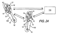
本発明のさらなる態様は、上述のとおりセンサーシステムを有する履物の物品を含むシステムに関連し、電子モジュールはセンサーシステムに接続し、また外部装置は、電子モジュールとの通信のために構成されている。モジュールは、センサーからのデータを受信し、データを外部装置に送信するよう構成されており、また外部装置は、さらにそのデータを処理するために構成されている。 A further aspect of the invention relates to a system comprising an article of footwear having a sensor system as described above, wherein the electronic module is connected to the sensor system and the external device is configured for communication with the electronic module. . The module is configured to receive data from the sensor and transmit the data to an external device, and the external device is further configured to process the data.
一つの態様によれば、システムはまた、電子モジュールと外部装置との間の通信を可能にするよう構成された外部装置に接続されたアクセサリ装置を含む。アクセサリ装置は、第二の外部装置へ接続して、電子モジュールと第二の外部装置との間の通信を可能にするためにも構成されうる。 According to one aspect, the system also includes an accessory device connected to the external device configured to allow communication between the electronic module and the external device. The accessory device can also be configured to connect to a second external device to allow communication between the electronic module and the second external device.
別の一つの態様によれば、外部装置に通信されるデータは、一つ以上の異なるアプリケーションで使用できる。こうしたアプリケーションには、その他のアプリケーションがある中で、ゲームプログラムなどの外部装置により実行されるプログラムや、運動競技のパフォーマンスの監視のための制御入力としてのデータの使用が含まれうる。運動競技のパフォーマンスの監視には、数ある中で、速度、距離、側方移動、加速、ジャンプの高さ、体重移動、足着地パターン、バランス、足 回内運動または回外運動、ランニング中の滞空時間測定、側方切断力、接触時間、圧力中心、体重分布、および/または衝撃力などのうち、一つ以上のパフォーマンス測定基準の監視が含まれうる。 According to another aspect, data communicated to an external device can be used in one or more different applications. Such applications may include, among other applications, programs executed by external devices, such as game programs, and the use of data as control inputs for athletic performance monitoring. Among other things, athletic performance monitoring includes speed, distance, lateral movement, acceleration, jump height, weight movement, foot landing pattern, balance, pronation or supination movement, and running Monitoring of one or more performance metrics may be included, such as airtime measurement, lateral cutting force, contact time, pressure center, weight distribution, and / or impact force.
本発明のなおもさらなる態様は、上述のとおりセンサーシステムを含む履物の物品を利用する方法に関連する。こうした方法には、センサーからのデータを電子モジュールで受信することと、モジュールからのデータをさらなる処理のために遠隔外部装置に送信することが含まれうるが、これは、一つ以上のアプリケーションでの使用を含みうる。こうした方法にはまた、第一の電子モジュールをセンサーシステムから取り外すかまたは接続を解除することと、第二のモジュールを所定位置に接続することが含まれうるが、第二のモジュールは異なる動作のために構成されている。こうした方法にはさらに、一つ以上のアプリケーションで使用するためにデータを処理すること、および/または外部装置用の制御入力としてデータを使用することが含まれうる。本発明の態様は、これらの方法の一つ以上の特徴の実行、および/または上述の履物およびシステムの利用で使用するための命令を含むコンピュータ可読媒体をも含みうる。 A still further aspect of the invention relates to a method of utilizing an article of footwear comprising a sensor system as described above. Such methods can include receiving data from the sensor at the electronic module and sending the data from the module to a remote external device for further processing, which can be done in one or more applications. May be included. Such methods may also include removing or disconnecting the first electronic module from the sensor system and connecting the second module in place, but the second module operates differently. Is configured for. Such methods may further include processing the data for use in one or more applications and / or using the data as a control input for an external device. Aspects of the invention may also include a computer-readable medium that includes instructions for performing one or more features of these methods and / or for use in utilizing the footwear and systems described above.
本発明の別の態様は、上述のとおりそれぞれがセンサーシステムを持つ、少なくとも二つの履物の物品を含むシステムであって、電子モジュールがそれに接続され、それぞれの電子モジュールがセンサーから受信したデータを外部装置に通信するために構成されているシステムに関連する。システムは、いくつかの通信モードを使用しうる。一つの実施形態において、各モジュールは個別に外部装置と通信する。別の実施形態において、モジュールは、追加的にまたは代替的に相互に通信するよう構成されている。さらなる実施形態において、一つの電子モジュールはデータをもう一方の電子モジュールに送信するよう構成され、そのもう一方の電子モジュールは両方の電子モジュールからのデータを外部装置に送信するよう構成されている。 Another aspect of the present invention is a system comprising at least two articles of footwear, each having a sensor system as described above, wherein an electronic module is connected thereto and each electronic module receives data received from the sensor externally. Relating to a system configured to communicate to a device. The system can use several communication modes. In one embodiment, each module communicates with an external device individually. In another embodiment, the modules are configured to additionally or alternatively communicate with each other. In a further embodiment, one electronic module is configured to transmit data to the other electronic module, and the other electronic module is configured to transmit data from both electronic modules to the external device.
本発明のなおもその他の特徴および利点は、以下の図面と併せた下記の明細書から明らかとなる。 Still other features and advantages of the present invention will become apparent from the following specification, taken in conjunction with the following drawings.
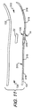
[図1] 図1は、靴の側面図である。
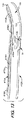
[図2] 図2は、図1の靴の反対側の側面図である。
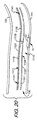
[図3] 図3は、センサーシステムの一つの実施形態を組み込んだ靴のソールの平面図である。
[図4] 図4は、図3のセンサーシステムを組み込んだ靴の側断面図である。
[図5] 図5は、図3のセンサーシステムを組み込んだ別の靴の側断面図である。
[図5A] 図5Aは、履物の物品のソール内にあるウェルに位置するポートの一つの実施形態の側断面図である。
[図5B] 図5Bは、履物の物品のソール内にあるウェルに位置するポートの第二の実施形態の側断面図である。
[図5C] 図5Cは、履物の物品のソール内にあるウェルに位置するポートの第三の実施形態の側断面図である。
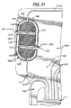
[図5D] 図5Dは、履物の物品のソール内にあるウェルに位置するポートの第四の実施形態の側断面図である。
[図5E] 図5Eは、履物の物品のソール内にあるウェルに位置するポートの第五の実施形態の平面図である。
[FIG. 2] FIG. 2 is a side view of the opposite side of the shoe of FIG.
[FIG. 3] FIG. 3 is a plan view of a shoe sole incorporating one embodiment of a sensor system.
[FIG. 4] FIG. 4 is a side sectional view of a shoe incorporating the sensor system of FIG.
FIG. 5 is a side sectional view of another shoe incorporating the sensor system of FIG.
FIG. 5A is a cross-sectional side view of one embodiment of a port located in a well in the sole of an article of footwear.
FIG. 5B is a cross-sectional side view of a second embodiment of a port located in a well in the sole of an article of footwear.
FIG. 5C is a cross-sectional side view of a third embodiment of a port located in a well in the sole of an article of footwear.
FIG. 5D is a cross-sectional side view of a fourth embodiment of a port located in a well in a sole of an article of footwear.
FIG. 5E is a plan view of a fifth embodiment of a port located in a well in the sole of an article of footwear.
本発明は数多くの異なる形態での実施形態が可能であるが、それらは図面に図示しており、また本開示は本発明の原理を例証したものとしてみなされ、よって本発明の広範な態様を図示および説明した実施形態に限定することは意図していないことが理解されるという前提で、本明細書において詳細な好ましい発明の実施形態が記述される。 While the invention is susceptible to embodiments in many different forms, they are shown in the drawings and the present disclosure is considered as illustrative of the principles of the invention, thus broadening the scope of the invention. Detailed preferred embodiments of the invention are described herein, with the understanding that it is not intended to be limited to the embodiments shown and described.
靴などの履物を、図1〜2に例として図示し、一般に参照番号100で指定する。履物100は、例えば、様々なタイプの運動靴を含む、数多くの異なる形態をとることができる。一つの例示的実施形態において、靴100は一般に、ユニバーサル通信ポート14に動作可能なかたちで接続された力センサーシステム12を含む。下記にさらに詳細に述べるとおり、センサーシステム12は靴100の装着者に関連するパフォーマンスデータを収集する。ユニバーサル通信ポート14への接続を通して、下記にさらに詳しく記載するとおり、複数の異なるユーザーが、各種の異なる用途でパフォーマンスデータにアクセスできる。
Footwear such as shoes is illustrated by way of example in FIGS. 1-2 and is generally designated by the
履物100の物品は、アッパー120およびソール構造130を含めたものとして図1〜2に図示されている。以下の説明での参照の目的で、履物100は、図1に図示したとおり、前足領域111、中足領域112、およびかかと領域113の3つの一般的な領域に区分しうる。領域111〜113は、履物100の正確なエリアの境界を定めることを意図していない。むしろ、領域111〜113は、下記の考察においての基準枠組みを提供する履物100の一般的なエリアを示すことを意図している。領域111〜113は、一般的に履物100に適用されるものの、領域111〜113への言及もまた、アッパー120、ソール構造130、もしくはアッパー120、またはソール構造130のいずれかの内部に含まれる、および/またはその一部を形成する個別の構成要素に特定的に適用されうる。
The article of
図1および2にさらに示したように、アッパー120は、ソール構造130に固定され、足を受け入れるための空隙またはチェンバを画定する。参照の目的で、アッパー120は、外側121、反対側の内側122、およびつま革または足の甲の領域123を含む。外側121は、足の外側(すなわち、外側)に沿って延びる位置にあり、 一般に各領域111〜113を通過する。同様に、内側122は、足の反対側の内側(すなわち、内側)に沿って延びる位置にあり、一般に各領域111〜113を通過する。つま革エリア123は、外側121と内側122の間に位置し、足の上面または足の甲の領域に相当する。この図示例において、つま革エリア123は、足に対してアッパー120の寸法を修正し、それにより履物100のフィットを調節する、ひも125または従来型の方法で利用されているその他の望ましい閉鎖機構を持つ、つま革の開き124を含む。アッパー120はまた、足にアッパー120内の空隙へのアクセスを提供する、足首の開口部126を含む。アッパー120を構築するために、履物のアッパーで従来的に利用されている材料を含めた、各種の材料を使用しうる。したがって、アッパー120は、例えば、皮革、合成皮革、天然または合成繊維、ポリマーシート、ポリマーフォーム、メッシュ繊維、フェルト、不織布ポリマー、またはゴム材料のうち一つ以上の部分から形成されうる。アッパー120は、これらの材料の一つ以上から形成されうるが、その材料または部分は、たとえば、当技術分野で従来的に知られており使用される方法で、縫って、または接着して一つに結合される。
As further shown in FIGS. 1 and 2, the upper 120 is secured to the
アッパー120は、かかと要素(非表示)およびつま先要素(非表示)も含みうる。かかと要素は、存在するとき、履物100の快適さを向上させるために、かかと領域113内で上方向かつアッパー120の内面に沿って延長しうる。つま先要素は、存在するとき、耐摩耗性を提供し、装着者のつま先を保護し、足の位置合わせを補助するために、前足領域111内かつアッパー120の外部表面に位置しうる。一部の実施形態において、かかと要素およびつま先要素の一方または両方はなくてもよく、またはかかと要素を、例えばアッパー120の外部表面上に位置付けてもよい。上記で考察したアッパー120の構成は履物100にとって適切ではあるが、アッパー120は、本発明から逸脱することなく、望ましい任意の従来型または非従来型のアッパー構造の構成を呈しうる。
ソール構造130は、アッパー120の下部表面に固定され、一般に従来型の形状を持ちうる。ソール構造130は、例えば、ミッドソール131、表底132、および足接触部材133(中敷き、シュトローベル(Strobel)、中底部材、ブーティ要素、靴下などが考えられる)を含むものなどの、マルチピース構造を持ちうる (図4〜5を参照)。図4〜5に示す実施形態において、足接触部材133は中底部材または中敷きである。「足接触部材」という用語が本明細書で使用されるとき、別の要素が直接的接触を妨げうるため、必ずしもユーザーの足との直接的な接触を意味するものではない。むしろ、足接触部材は、履物の物品の足を受け入れるチェンバの内面の部分を形成する。例えば、ユーザーは、直接的接触を妨げる靴下を履いていることがある。別の例として、センサーシステム12を、外部ブーティ要素または靴カバーなど、靴またはその他の履物の物品上で着脱されるように設計された、履物の物品に組み込みうる。こうした一つの物品において、ソール構造の上部部分は、ユーザーの足には直接的には接触しない場合でも、足接触部材とみなされうる。
ミッドソール部材131は、衝撃減衰部材としうる。例えば、ミッドソール部材131は、ポリウレタン、エチルビニルアセテート、またはその他の材料(ファイロン、フィライトなど)などの 圧縮して、ウォーキング、ランニング、ジャンプ、またはその他の活動時の地面またはその他の接触面の反作用力を減衰させる、ポリマーフォーム材料から形成しうる。本発明による一部の構造例において、ポリマーフォーム材料は、履物100の快適さ、動作制御、安定性、および/または地面またはその他の接触面の反作用力減衰特性を向上させる、液体を充填した袋または緩衝材(moderator)などの様々な要素をカプセル化または包含しうる。さらにその他の構造例において、ミッドソール131は、圧縮して地面またはその他の接触面の反作用力を減衰する追加的な要素を含みうる。例えば、ミッドソールは、力の緩衝作用および吸収を助ける支柱タイプの要素を含みうる。
The
表底132は、この図示例の履物構造100ではミッドソール131の下部表面に固定され、また歩行またはその他の活動時に地面またはその他の表面と接触するゴムなどの耐摩耗性材料またはポリウレタンなどの柔軟性のある合成材料から形成される。表底132を形成する材料は、適切な材料で製造したり、および/または摩擦および滑りの抵抗を向上させる加工を施しうる。表底132の構造および製造方法について、下記にさらに考察する。足接触部材133(中底部材、中敷き、ブーティ部材、Strobel、靴下などが考えられる) は、履物100の快適さを向上させるために、アッパー120の空隙の内部で、かつ足の下部表面に隣接して(またはアッパー120およびミッドソール131の間)に位置しうる、一般的に薄くて圧縮性の部材である。一部の配置において、中底または中敷きはなくてもよく、またその他の実施形態において、履物100は、中底または中敷きの上部に位置する足接触部材を持ってもよい。
The
図1および2に示す表底132は、表底132の片側または両側の複数の切込みまたはサイプ(sipes)136を含む。これらのサイプ136は、表底132の下部からその上部またはミッドソール131へと延びうる。一つの配置において、サイプ136は、表底132の下側表面から表底132の下部と表底132の最上部の間の中間点まで延びうる。別の配置において、サイプ136は表底132の下部から表底132の最上部までの中間を越えた点まで延びうる。また別の配列において、サイプ136は、表底132の下部から表底132がミッドソール131に接触する点まで延びうる。サイプ136は、表底132に追加的な柔軟性を提供しえ、それにより表底は装着者の足が曲がる自然な方向に、より自由に曲がることができる。さらに、サイプ136は、装着者のために摩擦の提供を助けうる。当然のことながら、本発明の実施形態は、その他のタイプおよび構成の靴、またその他のタイプの履物およびソール構造と関連して使用しうる。
The
図3〜5は、本発明に基づくセンサーシステム12を組み込んだ、履物100の例示的実施形態を図示する。センサーシステム12は、複数のセンサー16を持つ力センサー組立品13と、センサー組立品13と交信(たとえば、導体を介して電気的に接続)する通信または出力ポート14とを含む。図3に図示した実施形態において、システム12は、靴の親指(第一の趾骨)エリアにある第一のセンサー16Aと、第一の中足骨頭領域にある第二のセンサー16Bおよび第五の中足骨頭領域にある第三のセンサー16Cを含む靴の前足エリアにある2つのセンサー16B-Cと、かかとにある第四のセンサー16Dといった4つのセンサー16を持つ。これらの足のエリアは、一般に動作中に最も大きな度合いの圧力を経験する。下記の図27〜28に示す実施形態は、センサー16に類似した構成を利用する。各センサー16は、ユーザーの足によってセンサー16に対して及ぼされた力を検出するために構成されている。センサーは、ワイヤリード線および/または別の導電体または適切な通信媒体としうるセンサーリード線18を通してポート14と通信する。例えば、一つの実施形態において、センサーリード線18は、足接触部材133、ミッドソール部材131、または足接触部材133とミッドソール部材131との間の層などソール構造130の別の部材に印刷された電気的に導電性の媒体としうる。
3-5 illustrate an exemplary embodiment of
センサーシステム12のその他の実施形態は、後述の図8、図11〜21、および図27〜28に示す実施形態など、異なる数または構成のセンサー16を含むことができ、一般に少なくとも一つのセンサー16を含む。例えば、一実施形態において、システム12は、もっと大きな数のセンサーを含み、また別の実施形態において、システム12は、1個は靴のかかとで、もう1個は靴100のつま先にある2個のセンサーを含む。さらに、センサー16は、Bluetoothおよび近距離無線通信NFCを含めた、既知の任意のタイプの有線または無線の通信を含む、異なる方法でポート14と通信しうる。一足の靴は、対のそれぞれの靴内にセンサーシステム12を提供しうるが、対になったセンサーシステムは、協調的に動作しうるか、または互いに独立して動作しうること、またそれぞれの靴内のセンサーシステムは、互いに通信してもしなくてもよいことが理解される。センサーシステム12の通信については、さらに詳しく後述する。当然のことながら、センサーシステム12には、データ(たとえば、ユーザーの足の地面またはその他の接触面との相互作用からの圧力データ)の収集および保管を制御するためのコンピュータプログラム/アルゴリズムを備えることがあり、またこれらのプログラム/アルゴリズムは、センサー16、ポート14、モジュール22、および/または外部装置110内に格納および/またはそれらにより実行されうることが理解される。センサー16は、必要な構成要素(例えば、プロセッサ、メモリ、ソフトウェア、TX/RXなど)を、こうしたコンピュータプログラム/アルゴリズムの保管および/または実行 および/またはポート14および/または外部装置110へのデータおよび/またはその他の情報の直接的な(有線または無線)転送を達成するために、含みうる。
Other embodiments of the
センサーシステム12は、靴100のソール130内にいくつかの構成で配置することができる。図4〜5に示す例において、ポート14、センサー16、およびリード線18は、ポート14、センサー16、および/またはリード線18をミッドソール131の上側表面または足接触部材133の下側表面に接続することなどにより、ミッドソール131と足接触部材133との間に配置することができる。空洞またはウェル135は、後述するとおり、電子モジュールを受け入れるために、ミッドソール131(図4)内または足接触部材133(図5)内に位置することができ、ポート14は、ウェル135内からアクセスしうる。図4に示す実施形態において、ウェル135は、ミッドソール131上側の主な表面にある開口部により形成され、また図5に示す実施形態において、ウェル135は、足接触部材133の下側の主な表面にある開口部により形成される。ウェル135は、その他の実施形態において、ソール構造130内の他の場所に配置しうる。例えば、ウェル135は、一つの実施形態において、部分的に足接触部材133とミッドソール部材131の両方内に位置することも、ウェル135は、ミッドソール131の下側の主な表面または足接触部材133の上側の主な表面内に位置することもできる。さらなる実施形態において、ウェル135は、表底132内に位置することも、ソール130の側部、下部、またはかかとにある開口部を通すなど、靴100の外側からアクセス可能とすることもできる。図4〜5に図示した構成において、ポート14は、後述するとおり、電子モジュールの接続または接続の解除のために容易にアクセス可能である。その他の実施形態において、センサーシステム12は、異なるかたちで配置することができる。例えば、一つの実施形態において、ポート14、センサー16、および/またはリード線18は、表底132、ミッドソール131、または足接触部材133内に配置することができる。一つの例示的実施形態において、ポート14、センサー16、および/またはリード線18は、靴下、中敷き、内部フットウェアブーティ、またはその他の類似した物品など、足接触部材133の上側に配置された足接触部材133内に配置しうる。さらなる実施形態において、ポート14、センサー16、および/またはリード線18は、図12および図19〜20に示すものなど、足接触部材133とミッドソール131の間に、迅速かつ容易に挿入可能なように設計されたインサートまたはライナーに形成されうる。なおもその他の構成が可能であり、その他の構成の一部の例を下記に説明する。考察したとおり、当然のことながら、センサーシステム12は、対のそれぞれの靴に含めうる。
The
一つの実施形態において、センサー16は、特に履物100の使用時に、ソール130に及ぼされるかもしくは他の方法でそれと関連する応力、圧縮、またはその他の力および/またはエネルギーを測定するための力感知センサーである。例えば、センサー16は、力感知抵抗(FSR)センサーまたは力感知抵抗材料(量子トンネル効果型コンポジット、カスタム導電性フォーム、または力変換ゴムなどで、下記により詳しく記載)を利用したその他のセンサー、磁気抵抗センサー、圧電または圧抵抗センサー、ひずみゲージ、ばね型センサー、光ファイバー型センサー、偏光センサー、機械的アクチュエータ型センサー、変位型センサー、および/または足接触部材133、ミッドソール131、表底132などの力および/または圧縮を測定する能力のある、その他任意のタイプの既知のセンサーまたはスイッチとしうるか、またはそれを備えうる。センサーは、アナログ装置または力を定量的に検出または測定する能力を持つその他の装置としうるか、またはそれを備えうるか、または単にバイナリー型オン/オフスイッチ(たとえば、シリコン膜タイプのスイッチ)としうる。当然のことながら、センサーによる力の定量的測定は、モジュール22または外部装置110などの電子装置によって、定量的な力の測定値に変換しうるデータの収集および送信、または他の方法で利用可能とすることを含みうる。本書に記載したとおり、圧電センサー、力感知抵抗センサー、量子トンネル効果型コンポジットセンサー、カスタム導電性フォームセンサーなど、一部のセンサーは、測定した差異を、力の成分に変換できるように、抵抗、キャパシタンス、または電位の差異または変化を検出または測定できる。上記で言及したばね型センサーは、変形、または圧力および/または変形に起因する抵抗の変化を測定するよう構成できる。上述のとおり、光ファイバー型センサーは、光源およびそれに接続された光測定装置を備えた圧縮可能なチューブを含む。こうしたセンサーにおいて、チューブが圧縮されると、チューブ内の波長またはその他の光の特性が変化し、測定装置はこうした変化を検出し、その変化を力の測定値に変換できる。導電材料に浸したミッドソールなど、ナノコーティングを使用することもできる。偏光センサーを使用することができ、光伝送特性の変化が測定されて、ソールに及ぼされる圧力または力に関連付けられる。一つの実施形態では、複数アレイ(たとえば100)のバイナリーオン/オフセンサーが利用され、特定部位でのセンサー信号の「パドリング」により力成分が検出できる。本明細書で言及されていない、さらにその他のタイプのセンサーを使用しうる。当然のことながら、センサーは、比較的廉価なもので、大量生産プロセスで靴内への配置ができるものとすることができる。より高価でありうる、より複雑なセンサーシステムを、トレーニングタイプの靴に組み込むことができる。当然のことながら、異なるタイプのセンサーの組合せを一つの実施形態で使用しうる。
In one embodiment,
さらに、センサー16は、数多くの異なる方法で、靴構造とはまり合うように配置または位置づけしうる。一例において、センサー16は、靴100、または靴下、ブーティ、インサート、ライナー、中底、ミッドソールなどで使用するための、エアバッグまたはその他の液体を充填したチェンバ、フォーム材料、または別の材料などのソール部材上に配置された、印刷した導電性インクセンサー、電極、および/またはリード線としうる。センサー16および/またはリード線18は、例えば、衣服または布地構造を織ったり編んだりするときに導電性の布地または毛糸を使用して、衣服または布地構造(ソックライナー、ブーティー、アッパー、インサートなど)に織ることができる。センサーシステム12の数多くの実施形態は、後述および図8および11〜21に示すように、例えば、力感知抵抗センサーまたは力感知抵抗材料を使用することにより、廉価に作成できる。当然のことながら、センサー16および/またはリード線18は、従来的な配置技術により、導電性ナノコーティングにより、従来型な機械的コネクターにより、およびその他任意の適用される既知の方法などによって、任意の希望の方法で、靴構造の一部分上に配置したり、それと連動させることができる。センサーシステムは、機械的フィードバックを装着者に提供するよう構成することもできる。さらに、センサーシステム12は、電源を供給したり、またはセンサー16に対する接地の役目をしたりする、別々の電源リード線を含みうる。後述および図5A〜5Eおよび図27〜35に示す実施形態において、センサーシステム12、1312、1412、1512は、センサー16、1316、1416、1516をポート14、14A〜Eに接続して、モジュール22からセンサー16、1316、1416、1516に電源を供給するために使用する別々の電源リード線18A、1318A、1418A、1518Aを含む。さらなる例として、センサーシステム12は、印刷した導電性インクセンサー16または電極および導電性布地または毛糸のリード線18を組み込むことにより、またはそうしたセンサーを靴のフォームまたはエアバッグ上に形成することにより、作成できる。センサー16は、各種の方法でエアバッグ上、またはその内部に組み込みうる。一つの実施形態において、センサー16は、歪ゲージのような効果を達成するために、エアバッグ上の導電性の力感知材料を、エアバッグの一つ以上の表面上に印刷することで作成することができる。活動中にバッグの表面が膨張および/または収縮すると、センサーは、エアバッグに対する力を検出するために、力感知材料の抵抗の変化による変化を検出できる。一貫した形状を維持するために内部の織物を持つバッグにおいて、導電性材料をエアバッグの上部および下部に配置することができ、バッグが膨張および収縮する際の導電性材料間のキャパシタンスの変化を力を決定するために使用できる。さらに、空気圧の変化を電気的信号に変換できる装置を、エアバッグが圧縮されたときの力の決定に使用できる。
Further, the
ポート14は、センサー16により収集されたデータを、一つ以上の既知の方法で、外部のソースに通信するために構成されている。一つの実施形態において、ポート14は、普遍的に読取可能な形式でのデータの通信のために構成されたユニバーサル通信ポートである。図3〜5に示す実施形態において、ポート14は、図3でポート14に関連して示される電子モジュール22への接続のためのインターフェース20を含む。図3〜5に示す実施形態において、インターフェース20は、電気接点の形態をとる。さらに、この実施形態において、ポート14は、履物100の物品の中央のアーチまたは中足領域内のウェル135内に位置する電子モジュール22を挿入するために、ハウジング24を伴う。図3〜5でのポート14の位置決めは、最小限の接触、刺激、またはユーザーの足とのその他の干渉を呈するだけでなく、足接触部材133を単に持ち上げることによるアクセスの容易さを提供する。さらに、図6に図示したとおり、センサーリード線18はまた、ポート14およびポートインターフェース20への接続のために、その終端で統合インターフェースまたは接続19を形成する。一つの実施形態において、統合インターフェース19は、複数の電気接点を通してなど、センサーリード線18のポートインターフェース20への個別の接続を含みうる。別の実施形態において、センサーリード線18は、後述するプラグタイプのインターフェース、または別の方法など、外部インターフェース19を形成するために統合しうるが、またさらなる実施形態において、センサーリード線18は、各リード線18がそれ自身のサブインターフェースを持つ非統合インターフェースを形成しうる。図6に図示したとおり、センサーリード線18は、単一の場所に収束して統合インターフェースを形成しうる。また後述するとおり、モジュール22は、ポートインターフェース20および/またはセンサーリード線18への接続のためのインターフェース23を持ちうる。
ポート14は、各種の異なる電子モジュール22への接続のために適合されるが、これは、メモリ構成要素(たとえば、フラッシュドライブ)といった単純なものでもよく、またこれはより複雑な特徴を含みうる。当然のことながら、モジュール22は、パーソナルコンピュータ、モバイル機器、サーバーなどといった複雑な構成要素としうる。ポート14は、センサー16により収集されたデータの保管および/または処理のために、モジュール22に送信するために構成されている。別の実施形態において、ポート14は、必要な構成要素(例えば、プロセッサ、メモリ、ソフトウェア、TX/RXなど)を、こうしたコンピュータ プログラム/アルゴリズムの保管および/または実行、および/またはデータおよび/またはその他の情報の外部装置110への直接的な(有線または無線)転送を達成するために、含みうる。履物の物品内のハウジングおよび電子モジュールの例が、米国特許出願番号第11/416,458号(米国出願公開第2007/0260421号として公開)に図示されており、これを参照することにより本明細書に組み込み、その一部とする。ポート14は、モジュールへの接続のためのインターフェース20を形成する電子接点として図示されているが、その他の実施形態において、ポート14は、センサー16、モジュール22、外部装置110、および/または別のコンポーネントとの通信のための一つ以上の追加的または代替的な通信インターフェイスを含みうる。例えば、ポート14は、USBポート、ファイヤーワイヤーポート、16ピン式ポート、またはその他のタイプの物理的接触型の接続を含んだり、備えたりしうるか、またはWi-Fi、Bluetooth(登録商標)、NFC、RFID、Bluetooth(登録商標) Low Energy、Zigbee(登録商標)、またはその他の無線通信技術などの無線または非接触の通信インターフェース、もしくは赤外線またはその他の光通信技法(またはこうした技術の組合せ)のためのインターフェースを含みうる。
The
センサーリード線18は、各種の異なる構成でポート14に接続しうる。図5A〜5Eは、上述のとおり、ソール構造130のソール部材内など、履物100の物品のウェル135内に位置するポート14A〜Eの実施形態の例を図示する。図5A〜5Eに示す実施形態において、ウェル135は、側壁139およびベース壁143を含む複数の壁を持つ。
図5Aは、ポート14Aの実施形態を図示するが、ここで、4つのセンサーリード線18および電源リード線18Aは、ウェル135の単一の側壁139を通してポート14Aに接続される。図示した実施形態において、センサーリード線18は、ポート14Aのインターフェース20に接続される、5ピン式接続の形態での統合インターフェースを形成する。この構成において、リード線18、18Aは、ポートインターフェース20に接続され、統合インターフェースを形成し、各リード線18、18Aは、接続ピン62で終端処理し、複数ピン式接続を形成する。この接続ピン62は、一つの実施形態において、ウェル135内でアクセスが可能なリード線18、18Aの露出端であると見なすことができる。同様に、モジュール22は、ポートインターフェース20でのリード線18、18Aの接続ピン62への接続のための5ピン接続60を含む接続またはインターフェース23を持つ。
FIG. 5A illustrates an embodiment of
図5Bは、ポート14Bの実施形態を図示するが、ここで、2つのセンサーリード線18は、ウェル135の側壁139のうち一つを通してポート14Bに接続され、またその他の2つのセンサーリード線18および電源リード線18Aは、側壁139のうち別の一つを通してポート14Bに接続される。この実施形態において、リード線18は、外部インターフェース19の形態で2つの別個の統合リードインターフェース19を形成し、ポート14Bは、リード線18、18Aに接続するための2つの別個のインターフェース20を持つ。外部インターフェース19は、プラグタイプのインターフェース、ピンタイプのインターフェース、またはその他のインターフェースとすることができ、またポートインターフェース20は、外部リードインターフェース19に接続するために補完的に構成される。さらに、この構成において、モジュール22は、ポートインターフェース20への接続のために構成された2つのインターフェース23を持つ。
FIG. 5B illustrates an embodiment of port 14B, where two sensor leads 18 are connected to port 14B through one of the
図5Cは、ポート14Cの実施形態を図示するが。ここで、センサーリード線18および電源リード線18Aは、側壁139を通して、またウェル135のベース壁143を通してポート14C に接続される。この実施形態において、センサーリード線18は、ポート14Cに接続するためのいくつかの別個のリードインターフェース19を形成する。ポート14Cは、モジュールインターフェース23への接続のための、ポートインターフェース20への全てのリード線18、18Aの接続を統合する内部回路64を含む。ポート14Cはさらに、各リードインターフェース19への接続のための補完的なインターフェースを含みうる。当然のことながら、この実施形態において、リード線18、18Aは、ウェル135の一つ以上の側壁139を通して接続でき、また、リード線18、18Aは、例示の目的で、側壁139のうち2つを通して接続された状態で示している。この実施形態において、また当然のことながら、2本以上のリード線18、18Aを、ウェル135の特定の側壁139を通して接続でき、また1本のみのリード線18、18Aを、ベース壁143を通して接続しうる。
Although FIG. 5C illustrates an embodiment of
図5Dは、ポート14Dの実施形態を図示するが、ここで、4つのセンサーリード線18および電源リード線18Aは、ウェル135のベース壁143を通してポート14Dに接続される。図示した実施形態において、リード線18、18Aは、上述および図5Aに示す接続に類似した構成で、ポート14Dの下部でインターフェース20に接続された統合インターフェースを形成する。各リード線18、18Aは、ポートインターフェース20にある接続ピン62で終端処理され、また、モジュールインターフェース23は、リード線18、18Aの接続ピン62への接続のために構成された複数のピン接続60を含む。
FIG. 5D illustrates an embodiment of port 14D, where four sensor leads 18 and
図5Eは、ポート14Eの実施形態を図示するが、ここで、4つのセンサーリード線18および電源リード線18Aは、ウェル135の4つの側壁139のそれぞれを通してポート14Eに接続される。この実施形態において、リード線18、18Aは、上述および図5Cに示す実施形態と同様に、ポート14Eに接続するためのいくつかの別個のインターフェース19を形成する。上述のとおり、ポート14Eは、リードインターフェース19に接続するための補完的なインターフェースを含むことができ、また、モジュール22に接続するためのインターフェースを含みうる。その他の実施形態において、リード線18、18Aは、ウェル135の任意の数の側壁139を通して接続できる。
FIG. 5E illustrates an embodiment of
図5B、5C、および5Eに図示したものなどの実施形態においては、センサー18が複数のインターフェース19を形成し、ポート14B、14C、14Eおよび/またはモジュール22は、複数のインターフェース20、23を持ちうるか、または単一のインターフェース20、23のみを持ちえ、またポート14は、全てのリード線18、18Aをインターフェース20、23に接続するための内部回路64を持ちうる。さらに、モジュール22は、それへの接続のために、ポート14のインターフェース20に対して補完的な一つ以上のインターフェース23を持ちうる。例えば、ポート14が側壁139および/またはそのベース壁143内にインターフェース20を持つ場合、モジュール22は、同様に側壁および/またはベース壁内に補完的なインターフェース23を持ちうる。当然のことながら、モジュール22およびポート14は、同様に補完的なインターフェース20、23を持たなくてもよく、1対のみの補完的なインターフェース20、23が構成要素間の通信を達成できるようにしうる。その他の実施形態において、ポート14およびウェル135は、リード線18、18Aの接続のための異なる構成を持ちうる。さらに、ポート14は、より大きな多様性の接続構成を可能にしうる異なる形状を持ちうる。さらに、本書に記載した任意の接続構成、またはその組合せは、本書に記載したセンサーシステムの様々な実施形態と共に利用できる。
In embodiments such as those illustrated in FIGS. 5B, 5C, and 5E, the
モジュール22は、後述および図6に示すように、例えば処理のために、外部装置110に接続してデータを送信するための一つまたは複数の通信インターフェイスを追加的に持ちうる。こうしたインターフェースは、上述した任意の接触式または非接触式のインターフェースを含むことができる。一例において、モジュール22は、少なくとも、コンピュータに接続するための格納式USB接続を含む。別の例において、モジュール22は、腕時計、携帯電話、携帯音楽プレーヤーなどのモバイル機器への接触式または非接触式の接続のために構成されうる。モジュール22は、上述の格納式USB接続または別の接続インターフェースによるなど、履物100から取り外して、データ転送のために外部装置110に直接接続されるように構成しうる。一方で、別の実施形態において、モジュール22は、外部装置110を備えた無線通信用に構成しうるが、これにより必要に応じて、装置22を履物100内に留めることが可能となる。無線の実施形態において、モジュール22は、無線通信用のアンテナに接続しうる。アンテナは、選択した無線通信方法のために適切な伝送周波数で使用するための形状、サイズ、および位置づけをしうる。さらに、アンテナは、モジュール22の内部、またはポート14または別の場所でなど、モジュール22の外部に配置しうる。一例において、センサーシステム12それ自体(リード線18およびセンサー16の導電性部分など)を、アンテナの全体または一部を形成するために使用しうる。当然のことながら、モジュール22は、ポート14で、センサー16の一つ以上でなど、センサーシステム12の他の場所で接続されているアンテナに加えて、アンテナを含みうる。一つの実施形態において、モジュール22は、履物100内に永久的に取り付ることができるか、または代替的にユーザーの随意で着脱可能で、また必要に応じて履物100内に留めることができるようにしうる。さらに、下記にさらに説明するとおり、モジュール22は、取り外して、別の方法でセンサー16からのデータを収集および/または利用するためにプログラムおよび/または構成された別のモジュール22と交換しうる。モジュール22が、履物100内に永久的に取り付けられる場合、センサーシステム12は、図7に示すように、USBまたはファイヤーワイヤーポートなどのデータ転送および/または電池の充電を許容するための外部ポート15をさらに含みうる。こうした外部ポート15は、追加的または代替的に情報の通信用に使用しうる。モジュール22は、誘導充電など、非接触充電用にさらに構成しうる。当然のことながら、モジュール22は、接触式および/または非接触式の通信用に構成しうる。
The
ポート14は、本発明から逸脱することなく、各種の位置に配置しうるが、一つの実施形態において、ポート14は、たとえば、運動活動中など、装着者が履物100の物品を踏み込んだり、および/またはその他の方法で使用するとき、装着者の足との接触および/またはそれの刺激を避けるかまたは最小化するような位置および方向で提供される、および/またはその他の方法で構造化される。図3〜5のポート14の位置付けは、こうした一つの例を図示する。別の実施形態において、ポート14は、靴100のかかとまたは足の甲領域の近くに位置する。履物構造100のその他の特徴は、装着者の足とポート14(またはポート14に接続された要素)との間の接触を低減または回避し、履物構造100の全体的な快適さを改善するのに役立ちうる。例えば、図4〜5に図示したとおり、足接触部材133、またはその他の足接触部材は、ポート14の上にフィットし、少なくともそれを部分的にカバーすることができ、それによって、装着者の足とポート14の間にパッド層が提供される。装着者の足でのポート14との間の接触を低減し、望ましくない何らかの感覚を調節するための追加的な特徴を使用しうる。もちろん、必要に応じて、本発明から逸脱することなく、ポート14の開口部を、足接触部材133の上側表面を通して提供しうる。こうした構成は、例えば、ハウジング24、電子モジュール22、およびポート14のその他の特徴にユーザーの足での感覚を調節するための構造が含まれる、および/またはそれらがそのための材料で製造されているときや、追加的な快適さおよび感覚を調節する要素が提供されているときなどに使用しうる。装着者の足とハウジング(またはハウジング内に受け入れられる要素)との間の接触の低減または回避、および履物構造の全体的な快適さの改善に役立つ、上述の任意の様々な特徴は、図4〜5に関連して記載した様々な特徴、ならびその他の既知の方法および技術を含めて、本発明から逸脱することなく提供しうる。
Although the
ポート14が、ソール構造130内のウェル135に含まれるモジュール22を備えた接触式の通信用に構成されている一つの実施形態において、ポート14は、モジュール22への接続のためにウェル135の内部またはすぐ近くに配置される。当然のことながら、ウェル135がモジュール22のためのハウジング24をさらに含む場合、ポート14のための物理的空間を提供することにより、またはポート14とモジュール22との間の相互接続のためのハードウェアを提供することなどにより、ハウジング24はポート14への接続のために構成されうる。図3でのポート14の配置は、こうした一つの例を図示するもので、ハウジング24は、モジュール22への接続のためにポート14を受け入れる物理的空間を提供している。
In one embodiment where the
図6は、データ送信/受信システム106によるデータ送信/受信機能を含む電子モジュール22の例の概略図を示し、これは、本発明の少なくとも一部の例に従って使用されうる。図6の構造例は、データ送信/受信システム(TX-RX)106を電子モジュール構造22に統合されたものとして図示しているが、当業者であれば、発明の全ての例において、別個の構成要素が履物構造100の一部としてまたはデータ送信/受信用のその他の構造として含まれうること、および/またはデータ送信/受信システム106は、単一のハウジングまたは単一のパッケージ内に完全に含まれる必要はないことが理解される。むしろ、必要に応じて、データ送信/受信システム106の様々な構成要素または要素は、本発明から逸脱することなく、異なるハウジング内に、異なるボード上に分けられ、および/または各種の異なる方法で履物100の物品またはその他の装置と別々に連動されうる。異なる潜在的な取付け構造の様々な例を、下記に詳しく記載する。
FIG. 6 shows a schematic diagram of an example of an
図6の例において、電子モジュール22は、一つ以上のリモートシステムへのデータの送信および/またはそこからのデータの受信用のデータ送信/受信要素106を含みうる。一つの実施形態において、送信/受信要素106は、上述した接触式または非接触式のインターフェースによるなど、ポート14を通した通信のために構成されている。図6に示す実施形態において、モジュール22は、ポート14および/またはセンサー16への接続用に構成されたインターフェース23を含む。図3に図示したモジュール22において、インターフェース23は、ポート14と接続するために、ポート14のインターフェース20の接点に対して補完的な接点を持つ。その他の実施形態において、上述のとおり、ポート14およびモジュール22は、有線または無線としうる異なるタイプのインターフェース20、23を含みうる。当然のことながら、一部の実施形態において、モジュール22は、TX-RX素子106により、ポート14および/またはセンサー16とのインターフェースをとりうる。したがって、一つの実施形態において、モジュール22は、履物100の外側とすることができ、ポート14は、モジュール22との通信のための無線送信機インターフェースを備えうる。この例の電子的構成要素22は、処理システム202(たとえば、一つ以上のマイクロプロセッサ)、メモリシステム204、および電源206(たとえば、電池またはその他の電源)をさらに含む。電源206は、センサー16および/またはセンサーシステム12のその他の構成要素に電力を供給しうる。靴100は追加的にまたは代替的に、必要に応じて、電池、圧電、太陽光電源、またはその他など、センサー16を動作させる別個の電源を含みうる。
In the example of FIG. 6, the
一つ以上のセンサーへの接続は、TX-RX素子106により達成でき、また非常に多様な異なるタイプのパラメータに関するデータまたは情報を感知または提供するための追加的なセンサー(非表示)が提供されうる。こうしたデータまたは情報の例は、履物100の物品またはユーザーの使用に関連した物理的または生理学的データを含むが、これには、歩数計型の速度および/または距離の情報、その他の速度および/または距離のデータセンサー情報、温度、高度、気圧、湿度、GPSデータ、加速度計出力またはデータ、心拍数、脈拍数、血圧、体温、EKGデータ、EEGデータ、角度方向および角度方向の変化に関するデータ(ジャイロスコープベースのセンサーなど)などがあり、またこのデータは、例えば、送信/受信システム106によってどこかの遠隔の場所またはシステムに送信するために、メモリ204内に保管したり、および/または利用できるようにしうる。追加的なセンサーが存在する場合には、加速度計(たとえば、歩数計タイプの速度および/または距離の情報用など、ステップ時の方向の変化を感知するため、ジャンプの高さを感知するためなど)をも含みうる。
Connection to one or more sensors can be achieved by the TX-RX element 106, and additional sensors (not shown) are provided to sense or provide data or information on a wide variety of different types of parameters. sell. Examples of such data or information include physical or physiological data related to the
追加的な例として、履物の物品に対して自動衝撃減衰制御を提供するために、上述した様々なタイプの電子モジュール、システム、および方法を使用しうる。こうしたシステムおよび方法は、例えば、履物の物品の衝撃減衰特性を能動的および/または動的に制御するのためのシステムおよび方法を描写した、米国特許第6,430,843号、米国出願公開第2003/0009913号、および米国出願公開第2004/0177531号に記載のあるものと同様に動作しうる(米国特許番号第6,430,843号、米国出願公開第2003/0009913号、および米国特許出願公開番号第2004/0177531号は、それぞれ全体を参照し本書に組込み本明細書の一部とする)。速度および/または距離タイプの情報を提供するために使用するとき、米国特許番号第5,724,265号、第5,955,667号、第6,018,705号、第6,052,654号、第6,876,947号、および第6,882,955号に記載されたタイプの感知装置、アルゴリズム、および/またはシステムを使用しうる。これらの各特許は、参照によりその全体を本書に組込む。センサーおよびセンサーシステムの追加的な実施形態、ならびにそれを利用した履物の物品およびソール構造および部材については、米国特許出願公報第2010/0063778号および第2010/0063779号に記載があり、参照によりその出願書の全体を本明細書に組み込み、本明細書の一部とする。 As an additional example, the various types of electronic modules, systems, and methods described above may be used to provide automatic shock attenuation control for footwear articles. Such systems and methods are described, for example, in US Pat. No. 6,430,843, US Publication No. 2003/0009913, which describes systems and methods for actively and / or dynamically controlling the impact damping properties of an article of footwear. And U.S. Application Publication No. 2004/0177531 (US Pat. No. 6,430,843, U.S. Publication No. 2003/0009913, and U.S. Patent Application Publication No. 2004/0177531). Each of which is incorporated herein by reference in its entirety and made a part of this specification). When used to provide speed and / or distance type information, the types described in U.S. Pat.Nos. Sensing devices, algorithms, and / or systems may be used. Each of these patents is incorporated herein by reference in its entirety. Additional embodiments of sensors and sensor systems, as well as footwear articles and sole structures and components utilizing them, are described in US Patent Application Publication Nos. 2010/0063778 and 2010/0063779, which are incorporated herein by reference. The entire application is incorporated herein and made a part of this specification.
図6の実施形態において、電子モジュール22は、起動システム(非表示)を含みうる。起動システムまたはその部分は、電子モジュール22のその他の部分と共に、またはそれとは別個に、モジュール22と、または履物100の物品(またはその他の装置)と連動されうる。起動システムを、電子モジュール22および/または電子モジュール22の少なくとも一部の機能(たとえば、データ送信/受信機能など)を選択的に起動するために使用しうる。非常に多様な異なる起動システムを、本発明から逸脱することなく使用しうる。一例において、センサーシステム12は、連続的または交互のつま先/かかとタップ、または許容限界力を一つ以上のセンサー16に及ぼすなど、特定のパターンでセンサー16を起動することにより起動および/または解除しうる。別の例において、センサーシステム12は、モジュール22上に、靴100上に、またはセンサーシステム12と連通する外部装置上にある、並びにその他の位置に位置しうる、ボタンまたはスイッチにより起動しうる。これらの実施形態のいずれでも、センサーシステム12は、設定された無活動時間の後に、システム12を解除できる「スリープ」モードを含みうる。一つの実施形態において、意図的でない起動の場合に備えて、起動後の短時間内にその後の活動がなかった場合には、センサーシステム12は、「スリープ」モードに戻りうる。代替的な一つの実施形態において、センサーシステム12は、起動または解除をしない低消費電力装置として動作しうる。
In the embodiment of FIG. 6, the
モジュール22はさらに、外部装置110との通信用に構成しうるが、これは、図6に示すように、外部のコンピュータまたはコンピュータシステム、モバイル機器、ゲームシステム、またはその他のタイプの電子装置としうる。図6に示す例示的外部装置110は、プロセッサ302、メモリ304、電源306、ディスプレイ308、ユーザー入力310、およびデータ送信/受信システム108を含む。送信/受信システム108は、モジュール22の送信/受信システム106を介した、任意のタイプの既知の電子的通信による、モジュール22との通信のために構成されているが、これには、上記および本明細書の他の場所に記載した接触式および非接触式の通信方法が含まれる。当然のことながら、モジュール22は、非常に多様な異なるタイプおよび構成の電子装置を含めた、複数の外部装置との通信のために構成でき、またモジュール22が通信する相手の装置は、時間経過に伴い変更できる。さらに、モジュール22の送信/受信システム106は、複数の異なるタイプの電子通信用に構成しうる。さらに当然ながら、本書に記載したとおり外部装置110は、モジュール22と、ポート14と連通する、および/または、情報を外部装置110に渡す一つ以上の中間装置を含めた相互に連通する2つ以上の外部装置により具体化でき、また外部装置110の処理、プログラム/アルゴリズムの実行、およびその他の機能は、外部装置の組合せにより実施しうる。
上述のとおり、本発明に従い、数多くの異なるタイプのセンサーをセンサーシステムに組み込むことができる。図8は、複数の力感知レジスタ(FSR)センサー216を組み込んだセンサー組立品213を含むセンサーシステム212が含まれる靴100の一つの例示的実施形態を図示する。センサーシステム212は、上述のセンサーシステム12と類似したものであり、また、電子モジュール22と連通するポート14およびFSRセンサー216をポート14に接続する複数のリード線218も含む。モジュール22は、靴100のソール構造130にあるウェルまたは空洞135内に含まれ、ポート14は、ウェル135内でのモジュール22への接続を可能にするためにウェル135に接続される。ポート14およびモジュール22は、接続および通信のための補完的なインターフェース220、223を含む。
As mentioned above, many different types of sensors can be incorporated into a sensor system in accordance with the present invention. FIG. 8 illustrates one exemplary embodiment of a
図8に示す力感知レジスタは、第一および第二の電極または電気接点240、242と、電極240、242を一緒に電気的に接続するために電極240、242間に配置された力感知抵抗材料244とを含む。圧力が力感知材料244にかかると、力感知材料244の比抵抗および/または導電率が変化し、これが電極240、242間の電位を変化させる。抵抗の変化は、センサー216にかかる力を検出するセンサーシステム212により検出できる。力感応抵抗材料244は、様々な方法で圧力下でその抵抗を変化させうる。例えば、力感応材料244は、下記にさらに詳しく説明する量子トンネリング複合体に似た、材料が圧縮されたときに減少する内部抵抗を持ちうる。この材料をさらに圧縮するとさらに抵抗を減少することができ、定量的測定や、バイナリー(オン/オフ)測定が可能となる。一部の状況では、このタイプの力感知抵抗挙動は、「容量ベース抵抗」として説明されることがあり、この挙動を示す材料は、「スマート材料」と呼ばれることがある。別の例として、材料244は表面と表面の接触度合いを変化させることで抵抗を変化しうる。これは、圧縮されていない状態で表面抵抗を増加させるマイクロプロジェクションを表面に対して使用することにより(ここでマイクロプロジェクションが圧縮されると表面抵抗は減少する)、または別の電極との表面と表面の接触を増大させるように変形できる柔軟性のある電極を使用することによってなど、いくつかの方法で達成できる。この表面抵抗は、材料244と電極240、242との間の抵抗、および/または複数層材料244の導電層(例えば、炭素/グラファイト)と力感応層(例えば、半導体)との間の表面抵抗としうる。圧縮が大きいほど、表面と表面の接触が大きくなり、その結果、抵抗が低くなり、定量的測定が可能となる。一部の状況では、このタイプの力感知抵抗挙動は、「接触ベース抵抗」として説明されることがある。本明細書で定義するとおり、力感応抵抗材料244は、ドープまたは非ドープの半導体材料とするか、またはそれを含みうることが理解される。
The force sensing resistor shown in FIG. 8 is a force sensing resistor disposed between the first and second electrodes or
FSRセンサー216の電極240、242は、金属、炭素/グラファイト繊維または複合体、その他の導電性複合体、導電性ポリマーまたは導電性材料を含むポリマー、導電性セラミックス、ドープ半導体、またはその他任意の導電性材料を含む、任意の導電性材料で形成できる。リード線218は、溶接、ハンダ付け、ろう付け、接着による接合、留め具、またはその他任意の統合型または非統合型の接合方法を含む、適切な任意の方法により、電極240、242に接続できる。別の方法として、電極240、242および関連するリード線218 は、同じ材料の単一ピースで形成しうる。
The
図9〜10は、図8に示すFSRセンサー216など、センサー16内の力感知抵抗材料Mの使用を一般的に図示する。電極(+)および(−)は、図9に示すようにその間に電位P1を持つ。図10に示すように、力感知抵抗材料 Mが圧縮されると材料Mの抵抗が変化し、よって、電極(+)および(−)電荷間の電位P2が変化する。材料Mは、体積ベースの抵抗、接触型の抵抗、またはその他のタイプの力感知抵抗の挙動を利用しうる。例えば、図8におけるセンサー216の力感知抵抗材料244は、この方法で動作しうる。別の例として、下記および図16〜20に記載した、量子トンネル効果型コンポジット、カスタム導電性フォーム、力伝達ゴム、およびその他の力感知抵抗材料は、力感知抵抗の挙動を示す。当然のことながら、電極(+)および(−)の間に配置された材料Mでのサンドイッチ配置など、電極(+)および(−)は、異なる配置で位置付けられうる。
FIGS. 9-10 generally illustrate the use of force sensitive resistive material M in
図8に示す実施形態の例において、FSRセンサー216の電極240、242は、連動するか、または互いにかみ合う複数のフィンガー246を持ち、力感知抵抗材料244は、電極240、242を相互に電気的に接続するためにフィンガー246間に配置されている。図8に示す実施形態において、各リード線218は、モジュール22からそれぞれのリード線218が接続されているセンサー216に独立的に電力を供給する。当然のことながら、センサーリード線218は、各電極240、242からポート14に延びる別個のリード線を含むことができ、また本明細書の他の場所に記載されているとおり、モジュール22は、別個の電源リード線18A、1318Aを通すことによるなど、こうした別個のリード線を通して電極240、242に電力を供給しうる。
In the example embodiment shown in FIG. 8, the
センサーシステム212での使用に適した力感知レジスタは、Sensitronics LLCなどの供給元から市販されている。使用に適切でありうる力感知レジスタの例は、米国特許番号第4,314,227号および第6,531,951号に表示および記載されており、この全体を参照により本書に組込み、本明細書の一部とする。
Force sensing resistors suitable for use with
図27〜28は、履物100の物品に組み込むためのFSRセンサーシステム1312の別の実施形態を図示する。センサーシステム1312は、図3に示す構成と同様に、第一の趾骨(親指)エリア内に配置された第一のセンサー1316、第一の中足骨頭エリアに配置された第二のセンサー1316、第五の中足骨頭エリアに配置された第三のセンサー1316、およびかかとエリア内に配置された第四のセンサー1316といった4つのセンサー1316を含む。センサー1316はそれぞれ、センサー1316をポート14に接続するセンサーリード線1318を持つ。さらに、電源リード線1318Aは、ポート14から延び、4つの全てのセンサー1316に接続されている。電源リード線1318Aは、様々な実施形態において並列、直列、またはその他の構成で接続でき、また各センサー1316は、別の実施形態では個別の電源リード線を持ちうる。図28に示すように、各リード線1318、1318Aは、ポート14に接続されたモジュール(非表示)への接続およびデータの転送のためにポート14に接続される。当然のことながら、ポート14は、本書に記載した任意の構成を持ちうる。この実施形態において、リード線1318、1318Aは、図5Aに示すように複数の接続ピン62を備えた5ピン式接続に適するように位置付けられている。
FIGS. 27-28 illustrate another embodiment of an
図8に関連して上述したシステム212と同様に、センサーシステム1312の各センサー1316は、第一および第二の電極または電気接点1340、1342と、電極1340、1342をまとめて電気的に接続するために電極1340、1342の間に配置された力感知抵抗材料1344とを含む。力/圧力が力感知材料1344にかかると、力感知材料1344の比抵抗および/または導電率が変化し、これが電極1340、1342間の電位および/または電流を変化させる。抵抗の変化は、センサー1316にかかる力を検出するセンサーシステム1312により検出できる。さらに、FSRセンサー1316はそれぞれ、連動するか、または互いにかみ合う複数のフィンガー1346を持ち、力感知抵抗材料1344は、電極1340、1342を互いに電気的に接続するために、フィンガー1346間に配置されている。
Similar to
図27〜28に示すセンサーシステム1312の実施形態において、各センサー1316は、導電性金属層および金属層(非表示)上に接触面を形成する炭素層(カーボンブラックなど)により構成された2つの接点1340、1342を含む。センサー1316はまた、これも炭素(カーボンブラックなど)の層またはパドルで構成された力感知抵抗材料1344を含み、これは電極1340、1342の炭素接触面と接触している。炭素同士の接触によって、圧力下でより大きな導電率の変化を生成することができ、センサー1316の有効性が増大する。リード線1318、1318Aは、この実施形態において、接点1340、1342の金属層の材料と同一としうる導電性金属材料により構成される。一つの実施形態において、リード線1318、1318Aおよび接点1340、1342の金属層は、銀で構成される。
In the embodiment of
図27〜28に示すように、この実施形態の例において、センサーシステム1312は、後述するとおり、足接触部材133とミッドソール部材131の間など、組み合わせて履物の物品に挿入するためのインサート部材1337を形成する、2つの柔軟性のある層1366および1368で構成される。層は、柔軟性のあるポリマー材料など、柔軟性のある任意の材料で形成できる。一つの実施形態において、層1366、1368は、厚み0.05〜0.2mmの成形しやすい薄いマイラ(Mylar)材料で形成される。インサート1337は、まず第一の層1366上に、印刷などにより、リード線1318、1318Aおよびセンサー1316の電極1340、1342のトレースパターンで導電性金属材料を配置し、図27に示す構成を形成することにより構成される。次に、追加的な炭素接触層が、センサー1316の電極1340、1342をトレースしながら第一の層1366上に配置され、炭素力感知抵抗材料1344が、これも図27に示すように、第二の層1368上にパドルとして配置される。全ての材料が配置された後、電極1340、1342が、力感知抵抗材料1344のパドルと整列して、履物100の物品に挿入するためのインサート部材1337を形成するように、層1366、1368が、図28に示すように重ね合わせ法で配置される。当然のことながら、導電性金属材料および炭素材料1344は、互いに向かい合った層1366、1368の面上に配置される(例えば、最下層1366、1368の上側表面と、最上層1366、1368の下側表面)。一つの実施形態において、この方法で構成されたセンサーシステム1312は、10〜750 kPaの範囲の圧力を検出できる。さらに、センサーシステム1312は、この範囲の少なくとも一部全体にわたって圧力を高い感度で検出できる能力を持ちうる。
As shown in FIGS. 27-28, in the example of this embodiment, the
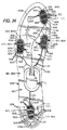
図29〜32は、履物100の物品に組み込むためのFSRセンサーシステム1412の別の実施形態を図示する。センサーシステム1412は、図3および図27〜28に示す構成と同様に、第一の趾骨(親指)エリア内に配置された第一のセンサー1416、第一の中足骨頭エリアに配置された第二のセンサー1416、第五の中足骨頭エリアに配置された第三のセンサー1416、およびかかとエリア内に配置された第四のセンサー1416といった4つのセンサー1416を含む。センサー1416はそれぞれ、センサー1416をポート14に接続するセンサーリード線1418を持つ。さらに、電源リード線1418Aは、ポート14から延び、4つの全てのセンサー1416に接続されている。電源リード線1418Aは、様々な実施形態において並列、直列、またはその他の構成で接続でき、また各センサー1416は、別の実施形態では個別の電源リード線を持ちうる。図29に示すように、各リード線1418、1418Aは、ポート14に接続されたモジュール(非表示)への接続およびデータの転送のためにポート14に接続される。当然のことながら、ポート14は、本書に記載した任意の構成を持ちうる。この実施形態において、リード線1418、1418Aは、図5Aに示すように複数の接続ピン62を備えた5ピン式接続に適すように位置付けされる。
FIGS. 29-32 illustrate another embodiment of an
図26〜28に関連して上述したシステム1312と同様に、図29〜32に示すセンサーシステム1412の各センサー1416は、第一および第二の電極または電気接点1440、1442と、電極1440、1442をまとめて電気的に接続するために電極1440、1442の間に配置された力感知抵抗材料1444とを含む。この実施形態において、図26〜28の実施形態と同様に、電極1440、1442は、下記にさらに詳しく記載するとおり、電極1440、1442および力感知材料1444が、表面間接触で互いに連動することができる向かい合った表面を持つように、力感知材料1444の表面と接触して位置する。圧力が力感知材料1444にかかると、力感知材料1444の比抵抗および/または導電率が変化し、これが電極1440、1442間の電位および/または電流を変化させる。抵抗の変化は、センサー1416にかかる力を検出するセンサーシステム1412により検出できる。さらに、FSRセンサー1416の電極1440、1442はそれぞれ、連動するか、または互いにかみ合う複数のフィンガー1446を持ち、力感知抵抗材料1444は、電極1440、1442を互いに電気的に接続するために、フィンガー1446間に配置されている。
Similar to the
図29〜32に示すセンサーシステム1412の実施形態において、図27〜28のセンサー1316に関連して上述したように、各センサー1416は、導電性金属層および随意に金属層上に接触面を形成する炭素層(カーボンブラックなど)により構成された2つの接点1440、1442を含む。センサー1416はまた、これも炭素(カーボンブラックなど)の層、パッチ、またはパドル1444Aで構成された力感知抵抗材料1444を含み、これは電極1440、1442の炭素接触面と接触している。リード線1418、1418Aは、この実施形態において、電極1440、1442の金属層の材料と同一としうる導電性金属材料により構成される。一つの実施形態において、リード線1418、1418Aおよび電極1440、1442 の金属層は、銀で構成される。
In the embodiment of
図32に示すように、力感知材料1444のパッチ1444Aは、互いに分離または実質的に分離している複数のローブ1470で形成される複数ローブ構造を持つ。図29〜32に示す実施形態において、力感知材料1444のパッチ1444Aは、隙間1471によって分離された3つのローブ1470を持つ。ローブ1470は互いに実質的に分離しており、またブリッジ1472がローブ1470間で電気的接続を形成するように、隙間1471を横断して延びるブリッジ1472により接続されている。図32の構成において、ローブ1470は、列を成して配置され、また3つのローブ1470間に2つの隙間1471を持ち、各隙間1471はそれを横切って架かるブリッジ1472を持つ。言い換えれば、列の中央のローブ1470は、その他の2つのローブ1470から隙間1471により分離され、隙間1471を横切って延びるブリッジ1472は、中央のローブ1470をその他の2つのローブ1470に接続している。さらに、この構成において、ブリッジ1472のうち一つは、パッチ1444Aの一方の外側に位置し、その他のブリッジ1472は、パッチ1444Aの反対側の外側に位置し、パッチ1444A に実質的なS型構造を与えている。さらに、隙間1471は、この実施形態において、直線で細長い構成を持ち、センサー1416が取り付けられているインサート1437の材料は、後述のとおり、隙間1471内に延びるスリット1476を持ちうる。その他の実施形態において、パッチ1444Aは、ローブでないか、または異なるように構成されたローブ1470、隙間1471、および/またはブリッジ1472を持つ異なる複数ローブ構造など、異なる構造を持ちうる。例えば、パッチ1444Aは、2ローブ構造を持ちうるか、または3つのブリッジ1472を持つ三角形状などの異なる構造を持つ3ローブ構造を持ちうるか、または相互に電気的に接続されていないローブ1470をさらに持ちうる。
As shown in FIG. 32, the
電極1440、1442は、この実施形態において、図31〜32に示すように、上述の電極1340、1342と同様に、スペースのあいた複数のフィンガー1446を持つ。各電極1440、1442は、力感知材料のパッチ1444Aのそれぞれのローブ1470と接触した複数のフィンガー1446のうち少なくとも一つを持つ。さらに、電極1440、1442はそれぞれ、フィンガー1446間のその他のスペースよりも大きい2つの拡張したスペース1473を持ち、スペース1473は力感知材料の隙間1471上に重なるように位置する。スペース1473のゆえに、電極1440、1442は、隙間1471内に位置するフィンガー1446を持たない。言い換えれば、この実施形態において、電極1440、1442は、力感知材料1444のパッチ1444Aに類似した、スペース1473により実質的に分離されたローブを有する実質的にS字型の複数ローブ構造を持つものと考えられうる。
In this embodiment, as shown in FIGS. 31 to 32, the
電極1440、1442と力感知材料1444の表面積の比または割合や、電極1440、1442のフィンガー1446間の間隔など、ある要因は、センサー1416の抵抗および出力に影響しうる。一つの実施形態において、電極1440、1442のフィンガー1446は、電極1440、1442の表面積の力感知材料1444の表面積に対する比が、約3:1から1:3の間になるように構成されるか、または言い換えれば、電極1440、1442は、力感知材料のパッチ1444Aの合計表面積のうち約25〜75%を覆う。別の実施形態において、電極1440、1442のフィンガー1446は、電極1440、1442の表面積の力感知材料1444の表面積に対する比が、約1:1になるように構成されるか、または言い換えれば、電極1440、1442は、力感知材料のパッチ1444Aの合計表面積のうち約50%を覆う。当然のことながら、これらの値は、電極1440、1442の周辺境界の内側または実質的に内側にある力感知材料1444の比または割合として測定でき、電極1440、1442の境界の外側にある追加的な力感知材料1444は、有意な影響を持たないことがある。さらに、フィンガー1446間の平均間隔は、一つの実施形態において0.25mmと1.5mmの間、また別の実施形態では約0.50mmとしうる。さらに、フィンガー1446は、一つの実施形態において約0.50mmの幅を持ちうる。これらの構成は、センサー1416にかかる力(たとえば、体重)の荷重とセンサー1416の抵抗との間、および/またはかかる力の荷重とセンサー1416の出力との間での望ましい関係または比例性を達成するにあたっての助けとなりうる。一つの実施形態において、センサー1416は、力の漸進的な増大に伴い、信号強度の漸進的な変化を生成するが、こうした関係は、本質的に直線または曲線となりうる。例えば、一つの実施形態において、これらの関係は1に近づく傾斜を持つ線形、言い換えれば、センサー1416の抵抗および/または結果的な出力信号は、かかる力に対しておよそ1:1の割合で増減する。かけられた力と抵抗/出力との間のこの関係により、信号はかけられた力に正比例する方法で変化するため、各センサー1416にかけられた力の正確な決定が可能となる。したがって、この実施形態において、センサーシステム1412は、センサー1416にかかった力を正確に反映する信号およびデータを生成でき、これはその他の目的があるなかで、例えば、センサー1416にかかる力を正確に測定するため、またはセンサー1416にかかる力の相対的差異を正確に決定するために使用できる。その他の実施形態において、センサー1416にかかる力は、抵抗および/または結果的な信号に対して異なる関係または比例性を持ちえ、また一つの実施形態においては、単純なバイナリー(オン・オフ)スイッチング関係でありうる。
Certain factors, such as the ratio or percentage of the surface area of the
図32に示すように、この実施形態の例において、センサーシステム1412は、後述するとおり、足接触部材133とミッドソール部材131の間など、組み合わせて履物の物品に挿入するためのインサート部材1437を形成するための、2つの柔軟性のある層1466および1468で構成される。層は、柔軟性のあるポリマー材料など、柔軟性のある任意の材料で形成できる。一つの実施形態において、層1466、1468は、薄いPET(例えば、Teslin)またはマイラ(Mylar)材料、または本書に記載した材料を含め、その他任意の適切な材料で形成される。一つ以上の追加的な保護層(非表示)も、インサート1437内に使用しうるが、これは第一の層と第二の層1466、1468と同一の材料または異なる材料で作成しうる。インサート1437は、まず第一の層1466上に、印刷などにより、リード線1418、1418Aおよびセンサー1416の電極1440、1442のトレースパターンで導電性金属材料を配置し、図29〜32に示す構成を形成することによって構成される。次に、ある場合には、追加的な炭素接触層が、センサー1416の電極1440、1442をトレースしながら第一の層1466上に配置され、炭素力感知抵抗材料1444が、これも図32に示すように、第二の層1468上にパドルまたはパッチ1444Aとして配置される。全ての材料が配置された後、電極1440、1442が、力感知抵抗材料1444のパドルと整列して、履物100の物品に挿入するためのインサート部材1437を形成するように、層1466、1468は、図32に示すように重ね合わせ法で配置される。層1466、1468は、一つの実施形態において、接着剤またはその他の結合材料によりまとめて接続でき、またその他の実施形態において、層1466、1468の接続には、ヒートシール、スポット溶接、またはその他の既知の技術など、各種のその他の技術を使用できる。一つの実施形態において、この方法で構成されたセンサーシステム1412は、10〜750 kPaの範囲の圧力を検出できる。さらに、センサーシステム1312は、この範囲の少なくとも一部の全体にわたって圧力を高い感度で検出できる能力を持ちうる。さらに、一つの実施形態において、一方または両方の層1466、1468は、使用および/または製造中に、層1466、1468間から空気を逃がすための一つ以上の通気孔1484をその中に持ちうる。単一の通気孔1484を、図31に図示する。一つの実施形態において、第二の層1468は、センサー1416の周辺領域からの換気ができるように、各センサー1416の近くに通気孔1484を持ちうる。
As shown in FIG. 32, in this example embodiment, the
図29〜32に図示したインサート1437は、図27〜28でのインサート1337の構成など、その他のインサート構成よりも少ない材料を使用しうる構成を持つ。インサート1437の構成は、引き裂きや裂け/亀裂の伝播への耐性、製造中または製造後の靴への挿入のしやすさにおいてなど、追加的な利点を提供しうる。この実施形態において、インサート1437は、外側の前足エリアまたは外側および内側のかかとエリアでなど、不必要なことがあるインサート1437領域の材料切抜き部分をいくつか持つ。この構成でのインサート1437は、ユーザーの足の中足および/または前足(すなわち、中足骨)領域によってはめ込まれるように構成された中央部分1474Aを持ち、第一の趾骨部分1474Bおよび中足部1474Aの反対側の端部から延びるかかと部分1474Cは、ユーザーの足のそれぞれ第一の趾骨領域およびかかと領域によってはめ込まれるように構成されている。当然のことながら、ユーザーの足の形状に応じて、第一の趾骨部分1474Bは、ユーザーの足の第一の趾骨領域のみにはまることができる。この実施形態において、第一の趾骨部分1474Bおよびかかと部分1474Cが、より広い中央部分1474Aから細長く延びるインサート材料の細片または舌革として構成されるように、中央部分1474Aの幅は、第一の趾骨部分1474Bやかかと部分1474Cの幅よりも大きい。本明細書で参照したとおり、インサート1437の部分の幅は、内外方向に測定され、長さは前後方向に測定される。図29〜32の実施形態において、センサー1416は、上述のとおり、図3のセンサー16A〜Dと同様に配置されている。第一の趾骨部分1474Bは、ユーザーの第一の趾骨がはまることになる、その上に位置するセンサー1416の一つを持ち、また、かかと部分1474Cは、ユーザーのかかとがはまることになる、その上のセンサー1416のうち別の一つを持つ。残りの2つのセンサー1416は、インサート1437の前足エリアの中央部分1474A上に位置し、特に、ユーザーの足のそれぞれ第一および第五の中足骨頭領域がはまることになる第一の中足骨頭領域と、第五の中足骨頭領域とに位置する。
The
図29〜32に示す実施形態において、インサート1437は、インサート1437周囲を画定し、また上述のとおり、いくつかの切り抜き部分のある周辺端1475を持つ。例えば、インサート1437は、第二から第五までの趾骨領域にまたはその周辺に切り抜き部分を持ち、またかかと部分1474Cの内側および外側の端に2つの切り抜き部分を持つ。別の方法で説明すると、周辺端1475は、中央部分1474Aの内側から第一の趾骨部分1474Bの内側に延びる前方内側端1475A、中央部分1474Aの外側から第一の趾骨部分1474Bの外側に延びる前方外側端1475B、中央部分1474Aの内側からかかと部分1474Cの内側に延びる後方内側端1475C、および中央部分1474Aの外側からかかと部分1474Cの外側に延びる後方外側端1475Dを持つ。前方外側端1475Bは、内方向に湾曲しているか、またはそうでなければ刻みのついた形状を持ち、切り抜き部分を形成しているが、一方で前方内側端1475Aは外方向に湾曲した形状を持つ。さらに、後方内側端1475Cおよび後方外側端1475Dはそれぞれ、少なくとも一つの内方向に湾曲したまたはその他の方法で刻みのついた端部を持ち、その他の切り抜き部分を形成する。切り抜き部分は、第一の趾骨部分1474Bおよびかかと部分1474Cに、その細長い片または舌革の構成を与える。当然のことながら、インサート1437は、任意の数の異なる構成、形状、および構造を持つことができ、異なる数および/または構成のセンサー1416を含み、異なるインサート構造または周辺形状を持ちうる。
In the embodiment shown in FIGS. 29-32, the
図29〜32のインサート1437は、インサート1437の材料に複数のスリット1476を追加的に持ち、これはインサート1437の曲げおよび折り曲げの特性に影響を与えうる。例えば、スリット1476は、センサー1416の圧縮時などに、インサート1437の周辺領域のより均一な折り曲げを可能にし、センサー1416に対して、より法線にちかい(すなわち、垂直の)力を生成する。センサー1416は、一般に曲げ力、ねじり力、またはせん断力よりも、法線力に対してより効果的に作動し、したがって、この結果、ノイズおよび/または歪みの少ない、よりきれいな信号となりうる。少なくともスリット1476のいくつかは、センサー1416の近くに配置することができ、インサート1437の周辺端1475から内方向に延びうる。さらに、スリット1476の一つ以上は、センサー1416の一つ以上の内部の隙間、ノッチ、刻みなどの中に配置しうる(上述の隙間1471など)。図29〜33に示す実施形態において、2つのスリット1476は各センサー1416の近くに位置し、各スリット1476は、力感知材料1444にあるローブ1470間の隙間1471の一つへと延びる。この実施形態において、スリット1476は細長く、インサート1437の材料を完全に通り抜けて延びる。さらに、スリット1476のいくつかは、インサート1437の周辺端1475から内方向に延び、そのほかは、完全にインサート1437の内部に位置し、周辺端とは接触しない。当然のことながら、インサート1437は、様々な実施形態において、センサー1416および/または構成の異なるスリット1476の境界にまで延びていない、追加的なスリット1476を含みうる。
The
インサート1437は、その上のグラフィックデザイン1485またはその他の印も含みうる。グラフィックデザイン1485は、インサート1437の層1466、1468のうち一方または両方に配置された一つ以上のグラフィック層1486上に提供されうる。図32に図示した実施形態において、インサート1437は、その上にグラフィックデザインまたは印1485を含む追加的なグラフィック層1486を含む。この実施形態において、グラフィック層1486は、第一の層1466の上に位置し、第一の層1466に対して封じられる。グラフィック層1486は、第一の層と第二の層1466、1468と同一の周辺形状およびプロフィールを持つが、別の実施形態においては、グラフィック層1486は、第一の層と第二の層1466、1468よりも小さい周辺サイズを含めた、異なる形状を持ちうる。さらに、グラフィック層1486は、その他の層1466、1468と同一の材料、または異なる材料で作成しうる。グラフィックデザイン1485は、任意の適切な構成を持ちうる。図33に示す一つの実施形態において、グラフィックデザイン1485は、センサー1416および/またはセンサーシステム1412のその他の構成要素の様式化された、または様式化されていない描画を含みうる。図33のグラフィックデザインには、センサー1416の大まかなサイズ、プロフィール形状および位置の描写が含まれる。
The
図33は、図29〜32のセンサーシステム1412の代替的な実施形態を図示するが、ここで、力感知材料1444に対する層1466、1468の向きおよび電極1440、1442の向きが逆になっている。言い換えれば、その上に導電材料を持ち電極1440、1442を形成する第一の層1466が、構造において下部の層として位置し、その上に力感知材料1444を持つ第二の層1468が、第一の層1466の上に位置する。層1466、1468、電極1440、1442、および力感知材料1444は、さもなければ、上述した同一の形態または構成で提供できる。さらに、図33に示すセンサーシステム1412の実施形態には、上記に言及したとおり、センサー1416の様式化された、または様式化されていないバージョンの形態でのグラフィックデザイン1485を持つグラフィック層1486が含まれるが、これは、ユーザーに対してセンサー1416が位置する場所を示すために使用できる。
FIG. 33 illustrates an alternative embodiment of the
図34〜35は、履物100の物品の組み込みのためのFSRセンサーシステム1512の別の実施形態を図示する。センサーシステム1512は、図29〜32に示す構成と同様に、第一の趾骨(親指)エリア内に配置された第一のセンサー1516、第一の中足骨頭エリアに配置された第二のセンサー1516、第五の中足骨頭エリアに配置された第三のセンサー1516、およびかかとエリア内に配置された第四のセンサー1516といった4つのセンサー1516を含む。図34〜35に示す実施形態のセンサーシステム1512は、数多くの面で、図29〜32に示す実施形態のセンサーシステム1412と同一に、または実質的に類似して構成しうる。したがって、センサーシステム1512の少なくとも一部の特徴は、簡潔にするために、あまり詳細に説明されないことがあるが、当然のことながら、差異が記載されている箇所を除き、図29〜32のセンサーシステム1416の記述は、センサーシステム1512の記述に組み込まれる。また当然のことながら、センサーシステム1512は、上述および図33に示す、センサーシステム1412の実施形態の任意の特性を持ちうる。
FIGS. 34-35 illustrate another embodiment of an
図34〜35に図示したセンサー1516は、図29〜32のセンサー1416と実質的に同一に構成される。この実施形態のセンサー1516 はそれぞれ、センサー1516をポート14に接続するセンサーリード線1518を持つ。さらに、電源リード線1518Aは、ポート14から延び、4つの全てのセンサー1516に電源を供給するために直列構成で4つの全てのセンサー1516に接続される。図29〜32におけるセンサー1416と同様に、センサーシステム1512の各センサー1516は、第一および第二の電極または電気接点1540、1542と、電極1540、1542をまとめて電気的に接続するために電極1540、1542の間に配置された力感知抵抗材料1544とを含む。この実施形態において、図29〜32の実施形態と同様に、電極1540、1542は、力感知材料1544の表面と接触して位置する。また、図29〜32の実施形態と同様に、電極1540、1542は、連動するかまたは相互にかみ合う複数のフィンガー1546を持つ。当然のことながら、センサー1516は、上記に図29〜32に関連して記述したものと同一の方法で構造化され、また同一の方法で同様に機能する。
The
図34に示すように、この実施形態において、力感知材料1544のパッチ1544Aは、互いに分離または実質的に分離している複数のローブ1470で形成される複数ローブ構造を持つ。力感知材料1544のパッチ1544Aは、図29〜32の力感知材料1444と実質的に同一に構成され、細長い隙間1571により分離されたローブ1570を持ち、ブリッジ1572が隙間1571を横切って延び、ローブ1570間に電気的接続を形成する。上述と同様に、パッチ1544Aは、実質的にS型構造を持ちうる。また上述したとおり、各電極1540、1542は、力感知材料1544のパッチ1544Aの各ローブ1570と接触した複数のフィンガー1546のうち少なくとも一つを持つ。さらに上述したとおり、この実施形態において、電極1540、1542は、力感知材料1544隙間1571の上に位置する2つの拡張したスペース1573を有する複数ローブ構造を持つ。
As shown in FIG. 34, in this embodiment, the patch 1544A of the force sensing material 1544 has a multi-lobe structure formed of a plurality of
図34〜35の実施形態において、センサーシステム1512は、図29〜32に関連して上述したとおり、組み合わせて履物の物品に挿入するためのインサート部材1537を形成するための、2つの柔軟性のある層1566および1568で構成される。上述のとおり、第一の層1566は、その上に位置する電極1540、1542およびリード線1518、1518Aを持つことができ、また第二の層1568は、その上に力感知材料1544を持ちうる。図34〜35から、この実施形態のインサート1537の周辺形状および周辺端1575の輪郭は、図29〜32のインサート1437のものとは異なり、インサート1537の形状は、図27〜28のインサート1337の形状とより類似していることがを見て取ることができる。当然のことながら、この実施形態のインサート1537は、グラフィックデザインまたは印(非表示)をも含みうるが、これは、上述および図32〜33に示すグラフィックデザイン1485およびグラフィック層1486と類似したグラフィック層(非表示)上に提供しうる。
In the embodiment of FIGS. 34-35, the
図34〜35のインサート1537 は、インサート1537の材料に複数のスリット1576を持ち、これはインサート1576を完全に通り抜けて延びうる。スリット1576は、隙間1571内で、またはその他の方法でセンサー1516内に内部的に延びることを含めて、センサー1516の近くに配置でき、また上述のインサート1437と同様に、インサート1537の周辺端1575から内方向に延びうる。図34〜35に示すインサート1537のスリット1576は、図29〜32のスリット1476とは異なって構成される。スリット1576の一部は、異なる長さおよび形状を持ち、またかかとセンサー1516は、力感知材料1544の隙間1571内にスリット1576を持たない。さらに、インサート1537は、センサー1516内には延びない多数のスリット1576を持ち、これには、インサート1537のかかと領域にあるセンサー1516の周辺に位置する複数の周辺スリット(集合的に、1576A)が含まれる。周辺スリット1576Aは、インサート1537のかかと領域での周辺端1575の輪郭に沿って湾曲したスリット1576であり、かかとセンサー1516の周囲で湾曲する。上述および図29〜32に示すスリット1476と同様、スリット1576は、センサー1516の圧縮時などに、インサート1537の周辺領域のさらに均一な折り曲げを可能にでき、センサー1516に対して、より法線に近い圧縮が生成されうる。例えば、インサート1537のかかと領域にある周辺スリット1576Aにより、かかとの圧縮時にインサート1537がセンサー1516の周辺で「カッピング」形状に折れ曲がるようになり、これによりセンサー1516に対してより法線に近い力が生成される。
The
図8および図27〜35に示すセンサーシステム212、1312、1412、1512、ならびに図27〜35に示すインサート1337、1437、1537は、図4および5に示すように、靴100内部の足接触部材133とミッドソール部材131の間に実施できる。一つの実施形態において、FSRセンサーシステム212、1312、1412、1512は、靴100の製造時に、アッパー120をミッドソール131および表底132に接続した後で、ミッドソール部材131の上方(およびシュトローベルstrobelが存在する場合にその上方)に挿入され、その後、足接触部材133をセンサーシステム212、1312、1412、1512上に挿入できる。さらに、一つの実施形態において、センサーシステム212、1312、1412、1512は、図12および図27〜35に示すインサート部材437、1337、1437、1537など、インサート部材の一部として挿入できる。図11〜14は、FSRセンサーを靴100などの履物の物品に実施する追加的な例を図示する。図11〜14に示す実施形態は、上述および図4に示すように、電子モジュール22を受け入れるためのその中のウェル135と、モジュール22への接続のためのポート14とを持つ、ミッドソール部材131を図示する。ところが、当然のことながら、ウェル135および/またはポート14は、図5に示すように全体的または部分的に足接触部材133の内部に、または靴100のほかの場所など、他の場所に配置しうる。
The
一例として、図11は、FSRセンサーシステム312を含む履物の物品のソール構造130の部分を図示するもので、ミッドソール部材131はそれに接続されたFSRセンサー組立品313を持つ。この実施形態において、FSRセンサー316は、ミッドソール部材131内に部分的に埋め込まれ、またセンサーリード線318は、ミッドソール部材131の上側表面に接続される。当然のことながら、ミッドソール部材131は、ミッドソール部材131内でそれらを保持するためにセンサー316を覆う層を持つことができ、またセンサー318は、全体的または部分的にミッドソール部材131内に埋め込むことができ、あるいは、ミッドソール部材131はセンサー316を挿入するための「ポケット」を持ちうる。ミッドソール部材131 は、それに接続されたポート14も持つ。ポート14は、センサーリード線318に接続され、ウェル135内に受け入れられる電子モジュール22との接続のためにウェル135内に位置する。センサーリード線318は、ポート14への接続のためにポート14に近接してインターフェース319を形成する。
As an example, FIG. 11 illustrates a portion of a
別の例として、図12は、FSRセンサーシステム412を含む履物の物品のソール構造130の一部を図示するもので、追加ソール部材437はFSRセンサー組立品413を含む。この実施形態において、追加ソール部材437は、足接触部材133とミッドソール部材131の間に挿入するよう構成されたインサートまたはライナーである。インサート437は、FSRセンサー416およびそれに接続されたセンサーリード線418を持つ。インサート437は、上述および図27〜28に示すインサート1337の構成と類似した構成を持ちうるか、またはは、別の構成を持ちうる。さらに、この実施形態において、インサート437は、FSRセンサー416と、センサーを所定位置に保持するためにその上に取り付けられたセンサーリード線418とを持つ、柔軟性のあるポリマーウェビング材料の薄い層である。当然のことながら、センサー416および/またはリード線418は、全体的または部分的に インサート437のポリマー 材料内に埋め込みうる。別の実施形態において、インサート437は、結合またはウェビング材料は何もなしに、完全にセンサー組立品413から構成しうる。インサート437はまた、ポート14へのセンサーリード線418の接続のために構成され、インサート437が足接触部材133とミッドソール131との間に位置するとき、センサーリード線418のインターフェース419は、ポート14によって接続するためにウェル135の内部またはそれに隣接するように位置し、電子モジュール22はウェル135内に受け入れられる。さらに、ソール構造130には、異なる構成のセンサー416 を持つ一つ以上のその他のインサート437を提供できる。これらのその他のインサート437は、足接触部材133を持ち上げて、1つのインサートを別の異なる構成のインサート437と置き換えることにより、取り外して置き換えが可能である。これにより、必要に応じて、単一の履物の物品は、異なる用途のために異なるセンサー416の構成で使用できるようになる。例えば、後述するとおり、センサーシステム412は、外部装置110との通信のために構成でき、また外部装置110で実行する異なるゲームまたはその他のプログラム用にセンサー416の異なる構成を使用できる。さらに、インサート437は、異なるサイズの数多くの異なる履物の物品で使用して、汎用性を提供できるようにする大きさにしうる。
As another example, FIG. 12 illustrates a portion of the
図13に示す代替的な一つの実施形態において、インサート、ライナー、またはその他の追加ソール部材437Aは、足接触部材133の上部に配置するためにセンサー組立品412Aと共に構成できる。このインサート437Aは、センサー416Aとそれに接続されたセンサーリード線418Aを持つ柔軟性のあるポリマー ウェビング材料を持つなど、上述のインサート437と同様に構成できる。センサー組立品412Aは、足接触部材133の周辺またはそれを通して延び、電子モジュール22への接続のためのウェル135内に配置されたポート14に接続されるよう構成されたインターフェース419A内で終端となる、拡張および/または統合されたワイヤリード線418A を含みうる。当然のことながら、このインサート437Aは、一部の状況において、インサート437Aがソール構造130の上部分を形成するため、「足接触部材」とみなしうる。上述したインサート437と同様に、インサート437Aは、取り外して、異なるセンサー416Aの構成を持つその他のインサート437Aと交換でき、また様々な異なるサイズを持つ履物内に配置するための大きさとしうる。
In an alternative embodiment shown in FIG. 13, an insert, liner, or other additional sole member 437A can be configured with the
別の代替的実施形態において、インサート部材は、足接触部材133またはミッドソール部材131など、別のソール部材に接続するために作成できる。このインサート部材は、センサー416、416Aおよびそれに接続されたセンサーリード線418、418Aを有する柔軟性のあるウェビング材料(ポリマーなど)を持つなど、上述および図12〜13に示すインサート437および437Aと類似したものとする。この構成により、完全なセンサーシステムを創出するために、センサー組立品413、413Aは、必要に応じて、ソール構造130の任意の部材上に取り付けることができる。インサート部材は、接着剤、留め具、溶接、ヒートシール、またはその他任意の適切な技法によるなど、数多くの異なる方法でソール部材 に接続可能としうる。当然のことながら、一つの実施形態において、インサート部材437、437Aは、ウェビング材料を持たないものとすることができ、センサー組立品413、413Aの電子的構成要素のみを含みうる。
In another alternative embodiment, the insert member can be made to connect to another sole member, such as
さらなる例として、図14は、FSRセンサーシステム512を含み、足接触部材133がそれに接続されたFSRセンサー組立品513を持つ、履物の物品のためのソール構造130の一部分を図示する。図14に図示した足接触部材133は、中底部材であるが、上述のとおり、足接触部材133は、履物の物品で使用するために、代替的にブーティ要素、シュトローベル(Strobel)、中敷き、靴下、またはその他のタイプの足接触部材としうる。この実施形態において、FSRセンサー516は、部分的に足接触部材133内に埋め込まれ、センサーリード線518は、足接触部材133の下側表面に接続される。当然のことながら、足接触部材133は、足接触部材133内にそれらを保持するためにセンサー516をカバーする層を持つことができ、またセンサー518は全体的または部分的に足接触部材133内に埋め込むことができるか、または足接触部材133は、センサー516を受けるためのポケットを持ちうる。センサーリード線518の端末は、ポート14への接続のために構成され、また、足接触部材133がミッドソール部材131の上に位置するとき、リード線518のインターフェース519が、ウェル135内に受け入れられた電子モジュール22とのポート14を通した接続のために、ウェル135の内部またはそれに隣接するように配置される。さらに、ソール構造130には、異なる構成のセンサー 組立品513を持つ複数の足接触部材133を提供できる。これらのその他の足接触部材133は、足接触部材133を取り外して、それを異なる構成のセンサー516を持つ別の足接触部材133で置き換えることにより、取り外して置き換えが可能である。これにより、必要に応じて、単一の履物の物品が、上述のとおり、外部装置110上で実行されるプログラムを含む、異なるアプリケーション用の異なるセンサー516の構成と併用できるようになる。
As a further example, FIG. 14 illustrates a portion of a
図15は、複数のセンサー616を組み込んだセンサー組立品613を含むセンサーシステム612が含まれる靴100の別の例示的な実施形態を図示する。センサー616は、電極640、642の対641と、電極640、642と接触する力感知抵抗材料644を含む別個の力感知抵抗素子650を利用する。この実施形態において、各電極の対641および力感知材料644は、組み合わせてセンサー616を形成し、上述および図9〜10に示す電極(+)および(−)および材料Mと同様に動作する。センサーシステム612は、上述のセンサーシステム12, 212と類似したように配置でき、また、電子モジュール22と連通するポート14および電極640、642をポート14に接続する複数のリード線618も含む。モジュール22は、靴100のソール構造130にあるウェルまたは空洞135内に含まれ、ポート14は、ウェル135内でのモジュール22へのの接続を可能にするためにウェル135内で接続される。
FIG. 15 illustrates another exemplary embodiment of a
図15の力感知抵抗素子650は、電極640、642と接触して配置される任意の要素とすることができる。力感知要素650は、完全に力感知抵抗材料644で構成することも、力感知材料644の層や、力感知材料644を含む戦略的に配置した領域を含むことによるなど、部分的にのみ力感知材料644で構成することもできる。さらに、力感知要素650は、1つの連続したピースとすることもでき、あるいはいくつかの別個のピースを含むこともできる。一つの実施形態において、後述および図16〜20に示す実施形態など、力感知要素650は、ソール構造130の部材内に含まれることも、ソール構造130の部材を全体的に形成することもできる。
The force
力感知抵抗材料244としての使用に適した1つの材料は、体積ベースの抵抗挙動を提供する量子トンネル効果型コンポジット(「QTC Quantum tunneling composite」)である。量子トンネル効果型コンポジットは、一般に、金属粒子またはその他の導電性粒子を含むポリマーマトリクス材料を含む。圧縮すると、導電性粒子は、互いに近づくように移動し、電子が絶縁性ポリマーマトリクスを通過して量子の機械的なトンネル効果が許容される。圧縮が増大するにつれて、導電性粒子は、互いにさらに近づき、より多くの電気的流れが許容され、測定される抵抗が減小する。量子トンネル効果型コンポジット内の粒子は、不規則な表面を持つことがあり、これによって粒子が互いに接触することなく、より大きな相対的範囲の粒子の動きが可能となる。この挙動により、力感知材料に対する力の定量的またはバイナリー(オン/オフ)検出が可能となる。適切な量子トンネル効果型コンポジット材料は、その他の供給元があるなかで、Peratech Limitedから入手できる。
One material suitable for use as the force sensing
力感知抵抗材料244としての使用に適した別の材料は、これも力感知抵抗動作を提供するカスタム導電性フォームである。カスタム導電性フォームは一般に、カーボンブラックまたは炭素のその他の形態、または導電性ポリマーなど、導電材料から製造されるか、または導電材料添加物を含むフォームを含む。カスタム導電性フォームにより、フォームが圧縮されるとより大きな電子の伝導が許容され、そのため測定される抵抗が減小する。力感知抵抗材料244としての使用に適したさらなる材料は、力変換ゴムである。力感知材料644は、体積ベースまたは接触型の抵抗を持つ上述の任意の材料を含む、力感知抵抗挙動を示すその他任意の材料としうる。
Another material suitable for use as the force
電極640、642は、電極240、242に関連して上述した、任意の材料から作成できる。一つの実施形態において、電極640、642および/またはリード線618は、足接触部材133、ミッドソール部材131、または別のソール部材などの表面に、導電性インクを使用して印刷することができる。別の実施形態において、この目的で導電性テープ、ならびに上述のその他の構造および技術を使用できる。
図15に示すセンサーシステム612は、力感知抵抗素子650を足接触部材133またはミッドソール部材131のいずれかに接続することなどにより、図4および5に示すように靴100内の足接触部材133とミッドソール部材131との間に実施することができる。図11〜20は、別個の力感知抵抗素子を使用して、センサーを靴100などの履物の物品に実施する追加的な例を図示する。図11〜20に示す実施形態は、上述および図4に示すように、電子モジュール22を受け入れるためのその中のウェル135と、モジュール22への接続のためのポート14とを持つ、ミッドソール部材131を図示する。ところが、当然のことながら、ウェル135および/またはポート14は、図5に示すように全体的または部分的に足接触部材133の内部に、または靴100のほかの場所など、他の場所に配置しうる。
The
一つの例として、図16は、センサーシステム712を含み、足接触部材133がそれに接続された電極組立品713 を持つ、履物の物品のためのソール構造130の一部分を図示する。この実施形態において、電極組立品713は、足接触部材133の下側表面に接続された電極対741およびセンサーリード線718を含む。一つの実施形態において、電極対741およびセンサーリード線718は、足接触部材133の下部に印刷することができ、および別の実施形態において、電極対741およびリード線718は、足接触部材133の下部の層内に含めることができる。当然のことながら、電極対741および/またはリード線718は、全体的または部分的に足接触部材133内に埋め込みうる。ミッドソール部材131は、力感知抵抗素子750を、その上側表面上の力感知抵抗材料744の層751の形態で含む。当然のことながら、この層751は、一部の実施形態において、連続的でなくてもよい。センサーリード線718は、ウェル135内に受け入れられた電子モジュール22とのポート14を通した接続のために、ウェル135の内部またはそれに隣接して配置されたインターフェース719を持つ。さらに、ソール構造130には、異なる構成の電極組立品713を持つ複数の足接触部材133を提供できる。これらのその他の足接触部材133は、足接触部材133を取り外して、それを異なる構成の電極対741を持つ別の足接触部材133で置き換えることにより、取り外して置き換えが可能である。これにより、必要に応じて、単一の履物の物品が、上述のとおり、外部装置110上で実行されるプログラムを含む、異なるアプリケーション用の異なるセンサーの構成と併用できるようになる。また当然のことながら、この構成は逆にでき、足接触部材133は、それに接続された力感知抵抗素子750を持ち、また電極対741は、ミッドソール部材131に接続しうる。
As one example, FIG. 16 illustrates a portion of a
図17に示す別の実施形態において、ソール構造130は、センサーシステム812を含み、足接触部材133は、上述および図16に示す電極組立品713と同一の構成の、それに接続された電極組立品813を持つ。上述と同様に、、電極組立品813は、足接触部材133の下側表面に接続された電極対841およびセンサーリード線818 を含み、リード線818は、ポート14への接続のためにインターフェース819で終端となる。ところが、図17の実施形態において、ミッドソール部材131それ自体が、力感知抵抗素子850として機能し、完全に力感知抵抗材料844から構成される。本実施形態は、さもなければ、図16に示す実施形態と同一の方法で機能し、同一の互換性を提供する。また当然のことながら、この構成は逆にでき、足接触部材133が力感知抵抗素子850として機能し、力感知抵抗材料844から構成され、電極対841は、ミッドソール部材131に接続されうる。
In another embodiment shown in FIG. 17, the
別の例として、図18は、センサーシステム912を含む履物の物品のためのソール構造130の一部分を図示するが、足接触部材133、ミッドソール部材131、および追加ソール部材937は、ミッドソール部材131と足接触部材133の間に位置する、それに接続された電極組立品713 を持つ。電極組立品913は、追加ソール部材937に接続された電極対941およびセンサーリード線918を含む。この実施形態において、追加ソール部材133は、電極対941を所定位置に保持するためにその上に取り付けられた電極対941およびセンサーリード線918を持つ、柔軟性のあるポリマーウェビング材料の薄い層から作成したインサート937である。当然のことながら、電極対941および/またはリード線918は、全体的または部分的にインサート937のポリマー材料内に埋め込みうる。別の実施形態において、インサート937は、結合またはウェビング材料なしに、完全に電極組立品913から構成しうる。ミッドソール部材131は、図16の力感知要素750と同様に、その上側表面上に、力感知抵抗材料944の層951の形態で力感知抵抗素子950を含む。当然のことながら、この層951は、一部の実施形態において、連続的でなくてもよい。インサート937はまた、ポート14へのセンサーリード線918の接続のために構成され、インサート937が足の接触133とミッドソール131との間に位置するとき、センサーリード線918のインターフェース919が、ウェル135内に受け入れられた電子モジュール22とのポートを通した接続のために、ウェル135の内部またはそれに隣接するように位置するように位置付けられる。さらに、ソール構造130には、異なる構成の電極組立品913を持つ複数のインサート937を提供できる。これらのその他のインサート937は、足接触部材133を持ち上げて、異なる構成の電極対941を持つ別のインサート937とインサート937を置き換えることにより、取り外して置き換えが可能である。これにより、必要に応じて、単一の履物の物品が、上述のとおり、外部装置110上で実行されるプログラムを含む、異なるアプリケーション用の異なるセンサーの構成と併用できるようになる。
As another example, FIG. 18 illustrates a portion of a
図19に示す別の実施形態において、ソール構造130は、センサーシステム1012を含み、インサート1037は、上述および図18に示す電極組立品913と同一の構成の、それに接続された電極組立品1013を持つ。上述と同様に、電極組立品1013は、ミッドソール部材131と足接触部材133の間に位置するインサート1037に接続された電極対1041およびセンサーリード線1018を含み、リード線1018は、ポート14への接続のためにインターフェース1019で終端となる。ところが、図19の実施形態において、ミッドソール部材131それ自体が、力感知抵抗素子1050として機能し、完全に力感知抵抗材料1044から構成される。本実施形態は、さもなければ、図18に示す実施形態と同一の方法で機能し、同一の互換性を提供する。当然のことながら、代替的な実施形態において、足接触部材133は力感知抵抗材料1044で構成でき、力感知抵抗素子1050として機能する。この構成において、インサート1037および/または電極組立品1013は、インサート1037の下側ではなく、上側にある力感知材料1044に接触するよう、再構成または再配置が必要となることがある。
In another embodiment shown in FIG. 19, the
当然のことながら、代替的な実施形態において、図18〜19に示すインサート937、1037は、力感知抵抗素子950、1050を含むか、またはそれを備えた足接触部材133と共に使用できる。足接触部材133が、ミッドソール部材131の上側表面上ではなく、その下側表面に位置する力感知抵抗材料944の層951を持つとき、インサート937および/または電極組立品913は、インサート937の下側ではなく、上側にある力感知材料944に接触するよう、再構成または再配置が必要となることがある。足接触部材133はまた、その上側に力感知材料944の層951を持つことがあり、その場合、インサート937、1037は、同様に上側に挿入できる。当然のことながら、足接触部材133全体が、力感知抵抗素子1050を備える場合、インサート937、1037は足接触部材133の上側または下側のどちらにも使用できる。
Of course, in alternative embodiments, the
図20に示す別の実施形態において、ソール構造130は、センサーシステム1112を含み、インサート1137は、上述および図18に示す電極組立品913と同一の構成の、それに接続された電極組立品1113を持つ。上述と同様に、、電極組立品1113は、ミッドソール部材131と足接触部材133の間に位置するインサート1137に接続される電極対1141およびセンサーリード線1118を含み、リード線1118は、ポート14への接続のためにインターフェース1119で終端となる。ところが、図20の実施形態において、力感知抵抗素子1150は、ミッドソール部材131または足接触部材133に取り付けられていない力感知抵抗材料1144の別個のライナー1151に含まれる。ライナー1151は、完全に力感知抵抗材料1144で構成することも、力感知材料1144から成る部分または領域を含むこともできる。さらに、この実施形態において、ライナー1151は、ミッドソール部材131とインサート1137の間に配置されるが、別の実施形態において、ライナー1151は、足接触部材133とインサート1137の間に配置しうる。当然のことながら、ライナー1151の位置が変化した場合、インサート1137および/または電極組立品1113は、インサート1137の下側ではなく、上側にある力感知材料1144に接触するよう、再構成または再配置が必要となることがある。さらに、その他の実施形態において、ライナー1151およびインサート1137は、電極対1141が力感知材料1144と接触している限り、ソール構造130のどこにでも配置できる。本実施形態は、さもなければ、図18に示す実施形態と同一の方法で機能し、異なる電極組立品の同一の互換性が提供される。本実施形態はまた、異なる材料1144が望ましい場合、または力感知要素が損傷または磨耗した場合などに、力感知要素1150の互換性を提供する。
In another embodiment shown in FIG. 20, the
別の代替的実施形態において、インサート部材は、足接触部材133またはミッドソール部材131など、別のソール部材に接続するために作成できる。このインサート部材は、上述のとおり、電極対941、1041、1141、および端部がポート14への接続のために構成されたセンサーリード線918、1018、1118 を持つ、柔軟性のあるウェビング材料(ポリマーなど)を持つなど、上述および図18〜20に示すインサート937、1037、1137と類似したものとしうる。この構成により、完全なセンサーシステムを創出するために、必要に応じて、電極組立品913、1013、1113を、ソール構造130の任意の部材上に取り付けることができる。インサート部材は、接着剤、留め具、溶接、ヒートシール、またはその他任意の適切な技法によるなど、数多くの異なる方法でソール部材 に接続可能としうる。当然のことながら、一つの実施形態において、インサート部材937、1037、1137は、ウェビング材料を持たないものとすることができ、センサー組立品913、1013、1113の電子的構成要素のみを含みうる。
In another alternative embodiment, the insert member can be made to connect to another sole member, such as
当然のことながら、量子トンネル効果型コンポジット、カスタム導電性フォーム、力伝達ゴム、および本明細書で考察したその他の力感知抵抗材料は、上述および図8に示す、FSRセンサー216と類似した個別の自己充足的センサーの作成に利用でき、また別個の電極および力感知要素を持つセンサー組立品での使用に限定されない。こうした個別のセンサーは、図9〜10に図示するように、2つの電極および力感知抵抗材料を含みうる。
Of course, quantum tunnel effect composites, custom conductive foams, force transfer rubbers, and other force sensing resistive materials discussed herein are separate and similar to the
図21に示す代替的な一つの実施形態において、センサーシステム1212は、ソール構造130ではなく、履物100の物品のアッパー120に接続されたセンサー組立品1213を含みうる。上述した異なるタイプのセンサーはどれも、この実施形態で使用でき、センサーは任意の適切な方法でアッパー120に接続できる。例えば、一つの実施形態において、センサー1216は、アッパー材料に織り込まれたFSRセンサーとしうるが、導電性織物もリード線1218を形成するためにアッパーに織り込まれる。この実施形態において、モジュール22は、靴100のソール130内に入っている状態で示され、リード線1218は、足接触部材133の下のアッパー120からモジュール22と連通するポート14に延びている。ところが、当然のことながら、モジュール22は、その他の実施形態において、アッパー120に取り付けることも含め、他の場所にも位置しうる。
In an alternative embodiment shown in FIG. 21, the
センサー/電極組立品413、413A、913、1013、および1113を持つ互換性のあるインサート437、437A、937、1037、および1137、ならびにセンサー/電極組立品513、713、および813を持つ互換性のある足接触部材133を含め、本明細書で上述の様々な互換性のあるソールインサートにより、手ごろな予算でのセンサーシステムのカスタム開発ができるようになる。例えば、FSRセンサーインサート437および437AならびにFSRセンサー組立品513を持つ足接触部材133は、様々な異なる供給元によって様々な目的で特注製造でき、また非常に多様な履物100に挿入することができる。別の例として、インサート937、1037、および1137ならびに電極組立品713、813、913、1013、および1113を持つ足接触部材133は、同様に特注製造ができ、また非常に多様な履物100に挿入できる。一つの実施形態において、履物100は、力感知抵抗材料を含めて製造ができ、また任意のセンサー組立品の構成713、813、913、1013、および1113を、履物100に挿入して力感知材料と共に機能させることができる。上述のとおり、力感知抵抗材料1144の別個のライナー1151も、非常に多様な履物に挿入するために製造することができ、システムの汎用性がさらに増大する。後述のとおり、こうしたセンサー組立品は、電子モジュール22および/または外部装置110用の特定のソフトウェアと併用するためにカスタム化ができる。サードパーティが、カスタム化されたセンサー組立品を持つソール インサートと共に、こうしたソフトウェアをパッケージとして提供しうる。
センサーシステム12、212、312、412、412A、512、612、712、812、912、1012、1112、1212、1312、1412、1512の動作および使用については、図3〜5に示すセンサーシステム12に関連して後述し、また当然のことながら、センサーシステム12の動作原理は、全ての実施形態およびその変形物を含めて、上述のセンサーシステム212、312、412、412A、512、612、712、812、912、1012、1112、1212、1312、1412、1512のその他の実施形態に適用される。作動中、センサー16は、その機能および設計に従いデータを集め、そのデータをポート14に送信する。次に、ポート14は、電子モジュール22が、センサー16とのインターフェースをとることを許容し、後の使用および/または処理のために、データを収集する。一つの実施形態において、各種の異なるアプリケーションで、各種の異なる目的での使用のために、複数のユーザーがデータにアクセスでき、および/またはダウンロードできるように、データは普遍的に読取可能な形式で収集、保存、および送信される。一例において、データは、XML形式で収集、保存、および送信される。さらに、一つの実施形態において、データは連続した方法でセンサー16から収集されることができ、また別の実施形態において、データは2つ以上のセンサー16から同時に収集されうる。
For the operation and use of
異なる実施形態において、センサーシステム12は、異なるタイプのデータを収集するように構成しうる。一つの実施形態において(上述)、センサー16は、圧縮の数、順序、および/または頻度に関するデータを収集できる。例えば、システム12は、履物100の着用中に発生したステップ、ジャンプ、カット、キック、またはその他の圧縮力の数または頻度、および接触時間および滞空時間などのその他のパラメータを記録できる。定量的センサーおよびバイナリーオン/オフタイプのセンサーの両方がこのデータを収集できる。別の例において、システムは、履物によって発生した圧縮力の順序を記録でき、これは、足の回内運動または回外運動、体重移動、足着地パターン、またはその他のこうした用途を決定するなどの目的で使用できる。別の実施形態において(上記にも記載)、センサー16は、靴100の隣接部分に対する圧縮力を定量的に測定することが可能であり、その結果としてデータは定量的な圧縮力および/または衝撃測定値を含みうる。靴100の異なる部分に対する力についての相対的差異は、体重分布および靴100の「圧力中心」の決定に利用できる。体重分布および/または圧力中心は、一方または両方の靴100について独立的に計算することができ、また人の身体全体についての圧力中心または体重分布の中心を求めるなど、両方の靴についてまとめて計算することもできる。上述のとおり、比較的高密度に実装されたアレイのオン/オフバイナリーセンサーを使用して、より大きな圧縮の瞬間時のセンサーの「パドリング」起動で検出された変化により、定量的力を測定することができる。さらなる実施形態において、センサー16は、圧縮力、接触時間、滞空時間または衝撃間の時間(ジャンプまたはランニングについてなど)、および/またはその他の時間的に依存するパラメータの変化率を測定することもできる。当然のことながら、任意の実施形態において、センサー16は、力/衝撃を登録する前にある一定の閾値の力または衝撃を要求しうる。
In different embodiments,
上述のとおり、データは、そのデータを使用できるアプリケーション、ユーザー、およびプログラムの数がほぼ無制限となるように、ユニバーサルポート14を通してモジュール22に普遍的に読取可能な形式で供給される。こうして、ポート14およびモジュール22は、ユーザーの希望に応じて構成および/またはプログラムされ、またポート14およびモジュール22は、センサーシステム12からの入力データを受信し、そのデータは、異なるアプリケーションに対して望ましい任意の方法で使用されうる。多くのアプリケーションにおいて、データは、使用の前に、モジュール22および/または外部装置110によりさらに処理される。当然のことながら、センサー16、ポート14、モジュール22、外部装置110(装置110Aを含む)、および/またはこうした構成要素の任意の組合せのうち一つ以上は、そうした構成要素が、処理機能を備えたハードウェアおよび/またはその他の構造を含んでいる場合に、一部の実施形態において、データの少なくとも一部分を処理しうる。外部装置110がデータをさらに処理する構成において、モジュール22は、データを外部装置110に送信しうる。この送信されたデータは、同一の普遍的に読取可能な形式で送信することも、別の形式で送信することもでき、またモジュール22は、データの形式を変更するように構成しうる。さらに、モジュール22は、一つ以上の特定のアプリケーション用に、センサー16からのデータを収集、利用、および/または処理するよう、構成および/またはプログラムすることができる。一つの実施形態において、モジュール22は、複数のアプリケーションで使用するために、データの収集、利用、および/または処理をするために構成されている。こうした使用およびアプリケーションの例を以下に示す。本書で使用するとき、「アプリケーション(application)」という用語は、一般に特定の用途を意味し、その用語がコンピュータ技術で使用されている時、コンピュータプログラムアプリケーションでの使用を必ずしも意味しない。それにもかかわらず、特定用途は、全体的または部分的に コンピュータプログラムアプリケーションで実現しうる。
As described above, data is provided in a universally readable form to the
さらに、図22の実施形態において図示したとおり、モジュール22は、履物100から取り外して、第一のモジュール22とは異なって動作するように構成された第二のモジュール22Aと置き換えることができる。当然のことながら、モジュール22は、電池の消耗、誤作動などによる交換など、取り外して、類似したまたは同一の方法で構成された別のモジュール22Aで置き換えることができる。図22の実施形態において、交換は、足接触部材133を持ち上げ、ポート14から第一のモジュール22を切り離し、ウェル135から第一のモジュール22を取り外した後、ウェル135に第二のモジュール22Aを挿入し、ポート14に第二のモジュール22Aを接続し、最後に足接触部材133を元の位置に配置することによって達成される。第二のモジュール22Aは、第一のモジュール22とは異なってプログラムおよび/または構成しうる。一つの実施形態において、第一のモジュール22は、一つ以上の特定のアプリケーションでの使用について構成し、第二のモジュール22Aは、一つ以上の異なるアプリケーションでの使用について構成しうる。例えば、第一のモジュール22は、一つ以上のゲームアプリケーションでの使用のために構成し、第二のモジュール22Aは、一つ以上の運動競技のパフォーマンスの監視アプリケーションのために構成しうる。さらに、モジュール22、22Aは、同一タイプの異なるアプリケーションでの使用について構成しうる。例えば、第一のモジュール22は、あるゲームまたは運動競技のパフォーマンスの監視アプリケーションでの使用について構成し、第二のモジュール22Aは、異なるゲームまたは運動競技のパフォーマンスの監視アプリケーションでの使用について構成しうる。別の例として、モジュール22、22Aは、同一のゲームまたはパフォーマンスの監視アプリケーション内での異なる使用について構成しうる。別の実施形態において、第一のモジュール22は、あるタイプのデータの収集をするよう構成し、および第二のモジュール22Aは、異なるタイプのデータの収集をするよう構成しうる。定量的力測定、相対的力測定(すなわち、互いに相対的なセンサー16)、体重の移動/伝達、衝撃の順序(足着地パターンについてなど)、力の変化率などを含む、データタイプの例が本書に記載されている。さらなる実施形態において、第一のモジュール22は、第二のモジュール22Aとは異なる方法でセンサー16からのデータを利用または処理するように構成しうる。例えば、モジュール22、22Aは、データの収集、保存、および/または通信のみのために構成し、モジュール22、22Aは、データの整理、データ形式の変更、データを使用した計算の実行などいくつかの方法でデータをさらに処理するよう構成しうる。また別の実施形態において、モジュール22、22Aは、異なる通信インターフェイスを持ったり、異なる外部装置110と通信するよう構成されているなど、異なって通信するよう構成しうる。モジュール22、22Aは、異なる電源を使用する、または上述のとおり追加的なセンサーなど、追加的または異なるハードウェア構成要素(たとえば GPS、加速度計など)を含むなど、構造的および機能的な態様の両方を含め、その他の態様でも異なって機能しうる。
Further, as illustrated in the embodiment of FIG. 22, the
システム12によるデータ収集のために意図された一つの用途は、体重移動の測定でのものであり、これはゴルフのスイング、野球/ソフトボールのスイング、ホッケーのスイング(アイスホッケーまたはフィールドホッケー)、テニスのスイング、ボール投げ/投球など、数多くの運動活動にとって重要である。システム12により収集した圧力データは、適用される任意の運動分野での技法向上における使用に対して、バランスおよび安定性に関する価値の高いフィードバックを与えることができる。当然のことながら、それによって収集されるデータの使用目的に基づき、値段や複雑度が高いまたは低いセンサーシステム12を設計しうる。
One intended use for data collection by the
システム12により収集したデータは、各種のその他の運動競技のパフォーマンス特性の測定に使用できる。データは、足の回内/回外運動の度合いおよび/または速度、足着地パターン、バランス、およびそうしたその他のパラメータを測定するために使用でき、ランニング/ジョギングまたはその他の運動活動での技法を向上するために使用できる。回内/回外運動に関しては、データの分析は、回内/回外運動の予測因子として使用することもできる。速度および距離の監視を実行できるが、これは、接触測定または滞空時間測定など、歩数計ベースの測定を含みうる。接触または滞空時間の測定を使用することなどにより、ジャンプの高さも測定できる。カッティング時に靴100の異なる部分にかかる力の差を含め、側方切断力を測定できる。センサー16は、靴100内の横方向の足のスリップなど、せん断力を測定するためにも配置できる。一例として、側面に対する力を感知するために、靴100のアッパー120の側面に追加的なセンサーを組み込みうる。別の例として、高密度のアレイのバイナリーセンサーは、起動したセンサーの「パドリング」における外側の変化によってせん断作用を検出できる。
The data collected by the
別の実施形態において、上述のとおり、一つ以上のセンサー1216を、靴100のアッパー120に追加的または代替的に組み込むことができる。センサー1216は、上述の任意の方法でアッパー120に組み込むことができる。例えば、センサー1216は、アッパーの材料に織り込みうるが、導電性織物もリード線を形成するためにアッパーに織り込まれる。この構成において、サッカーまたはフットボールなどでのキック力や、サッカーでの「タッチ」の数および/または頻度などの追加的なパラメータを測定できる。
In another embodiment, as described above, one or
そこから得られたデータまたは測定値は、速度、パワー、機敏さ、一貫性、技法などの向上を含めて、運動トレーニングの目的で有用でありうる。ポート14、モジュール22、および/または外部装置110は、ユーザーに能動的でリアルタイムのフィードバックを与えるように構成できる。一例において、ポート14および/またはモジュール22は、結果をリアルタイムで伝達するために、コンピュータ、モバイル機器などと通信可能に配置できる。別の例において、靴の一部分を振動させることにより動作の制御を助けることで、ユーザーにフィードバックを与えることができる一つ以上の振動要素を靴100に含めうるが、これには、米国特許番号第6,978,684号に記載のある特徴などがあり、これを参照し本書に組込み、本明細書の一部とする。さらに、データは、ある動作をユーザーの過去の動作と比較して一貫性、上達、またはその欠如を示したり、またはユーザーの動作を、プロゴルファーのスウィングなど他者の同一の動作と比較するなど、運動動作を比較するために使用できる。さらに、システム12は、ある運動選手の「特徴的な」運動動作のための生体力学データを記録するために使用しうる。このデータは、ゲームアプリケーションでの使用、またはある動作をユーザーの類似した動作に重ねるシャドーアプリケーションなど、動作の再現または模擬での使用のために、他者に提供しうる。
The data or measurements obtained therefrom can be useful for exercise training purposes, including improvements in speed, power, agility, consistency, technique, etc.
システム12は、ユーザーが一日全体で携わる様々な活動を記録するために、「一日中の活動」追跡用に構成することもできる。システム12は、モジュール22、外部装置110、および/またはセンサー16などに、この目的用の特殊なアルゴリズムを含みうる。
The
システム12は、データ収集および処理の用途ではなく、制御の用途での使用もしうる。言い換えれば、システム12は、センサー16により検出されたユーザーの動作に基づいて、コンピュータ、テレビ、ビデオゲームなどの外部装置110の制御に使用するために、履物、または体との接触をする別の物品に組み込みうる。実際には、組み込まれたセンサー16とユニバーサルポート14に延びるリード線18とを備えた履物により、履物が入力システムの役割を果たすことができ、また電子モジュール22は、センサー16からの入力を受信し、例えばリモートシステムのための制御入力としてなど、この入力データを任意の希望の方法で使用するように構成、プログラム、および適合できる。例えば、センサー制御を備えた靴は、コンピュータ用の、またはコンピュータにより実行中のプログラム用の制御または入力装置として、ある一定の足動作、ゼスチャーなど (たとえば、フットタップ、ダブルフットタップ、かかとタップ、ダブルかかとタップ、サイドツーサイドの足動作、フットポイント、フットフレックスなど)が、コンピュータ上の予め指定された動作(たとえば、ページダウン、ページアップ、元に戻す、コピー、カット、貼り付け、保存、閉じる、など)を制御できる場合に、マウスと同様に使用しうる。この目的で足のゼスチャーを異なるコンピュータ機能制御に割り当てるために、ソフトウェアを供給できる。オペレーティングシステムは、センサーシステム12からの制御入力を受信し認識するよう構成しうることが意図されている。テレビまたはその他の外部電子装置を、この方法で制御できる。システム12を組み込んだ履物100は、特定の動作をある一定の機能に割り当てることができ、および/またはユーザーの動作の仮想的表示を表示画面に生成するために使用できる、Nintendo Wii コントローラと同様に、ゲームアプリケーションおよびゲームプログラムでも使用できる。一例として、圧力中心データおよびその他の体重分布データは、バランス、体重移動、およびその他のパフォーマンス活動の仮想的表示が関与しうるゲームアプリケーションで使用できる。システム12は、ゲームまたはその他のコンピュータシステム用の専用コントローラとして、または補完的なコントローラとして使用できる。こうした制御についての外部装置および足のゼスチャーの制御としての履物の物品のためのセンサーシステムを使用する構成および方法の例は、米国仮出願番号第61/138,048号に表示および記述があり、これを参照することにより、この全体を本明細書に組み込む。
さらに、システム12は、直接的に外部装置110、および/または外部装置用のコントローラと通信できるように構成しうる。上述のとおり、図6は、電子モジュール22と外部装置との間の通信のための一つの実施形態を図示する。図23に示す別の実施形態において、システム12は、外部ゲーム装置110Aとの通信用に構成できる。外部ゲーム装置110Aは、図6に示す模範的外部装置110と類似した構成要素を含む。外部ゲーム装置110Aはまた、ゲームプログラム(たとえば、カートリッジ、CD、DVD、Blu-Ray、またはその他の記憶装置)を含む少なくとも一つのゲーム媒体307、および送信/受信要素108を通して有線および/または無線接続で通信するよう構成された少なくとも一つのリモコン305を含む。図示した実施形態において、コントローラ305は、ユーザー入力310を補完するが、一つの実施形態において、コントローラ305は、唯一のユーザー入力として機能しうる。この実施形態において、システム12には、外部装置110および/またはコントローラ305と接続してモジュール22との通信を可能にするように構成された、USBプラグインを有する無線送信機/受信機など、アクセサリ装置303が提供される。一つの実施形態において、アクセサリ装置303は、コントローラ305および外部装置110と同一および/または異なるタイプの一つ以上の追加的なコントローラおよび/または外部装置に接続するよう構成しうる。当然のことながら、システム12が上述のその他のタイプのセンサー(たとえば、加速度計)を含む場合、こうした追加的なセンサーは、ゲームまたは外部装置110上のその他のプログラムの制御に組み込むこともできる。
Further, the
コンピュータ/ゲームシステムなどの外部装置110には、システム12と相互作用するその他のタイプのソフトウェアを提供できる。例えば、ゲームプログラムは、ユーザーの現実の活動に基づきゲーム内のキャラクターの属性を変更するよう構成しうるが、これにより、ユーザーによるエクササイズまたはさらなる活動を奨励できる。別の例において、プログラムは、靴の感知システムにより収集されたユーザーの活動に関連または比例して動くユーザーのアバターを表示するよう構成しうる。こうした構成において、ユーザーが活動的であった場合、アバターは活気がある、精力的であるなどのように見え、またユーザーが活動していなかった場合、アバターは、眠たい、怠惰であるなどのように見えうる。センサーシステム12は、運動選手の「特徴的な動き」を描写するデータを記録するための、より精巧な感知をするよう構成することもでき、その後これが、ゲームシステムまたはモデリングシステムでなど様々な目的で利用される。
The
本書に記載したとおり、センサーシステム12を含む履物100単一のの物品は、単独で、または図24〜26に図示した、一足の靴100、100'など、それ自体のセンサーシステム12'を持つ、履物100'の第二の物品との組合せで使用できる。第二の靴100'のセンサーシステム12'は一般に、センサーリード線18'によって、電子モジュール22'と連通するポート14'に接続された一つ以上のセンサー16'を含む。図24〜26に示す第二の靴100'の第二のセンサーシステム12'は、第一の靴100のセンサーシステム12と同一の構成を持つ。ところが、別の実施形態において、靴100、100'は、異なる構成を持つセンサーシステム12、12'を持ちうる。2つの靴100、100'は、どちらも外部装置110との通信用に構成され、また図示した実施形態において、それぞれの靴100、100'は、外部装置110と通信するよう構成された電子モジュール22、22'を持つ。別の実施形態において、両方の靴100、100'は、同一の電子モジュール22と通信するよう構成されたポート14、14'を持ちうる。この実施形態において、少なくとも一つの靴100、100'は、モジュール22との無線通信をするよう構成しうる。図24〜26は、モジュール22、22'間の通信のための様々なモードを図示する。
As described herein, a single article of
図24は、「メッシュ」通信モードを図示するが、ここで、モジュール22、22'は、相互に通信するように構成され、また外部装置110との独立した通信をするようにも構成されている。図25は、「デイジーチェーン」通信モードを図示するが、ここで、1つのモジュール22'は、その他のモジュール22を通して外部装置110と通信する。言い換えれば、第二のモジュール22'は、信号(これには、データを含みうる)を第一のモジュール22に通信するように構成され、また第一のモジュール22は、モジュール22、22'の両方からの信号を外部装置110に通信するように構成されている。同様に、外部装置は、信号を第一のモジュール22に送信することにより、第一のモジュール22を通して第二のモジュール22'と通信するが、これが信号を第二のモジュール22'に通信する。一つの実施形態において、モジュール22、22'はまた、外部装置110との間で信号の送受信をする以外の目的で相互に通信することもできる。図26は、「独立」通信モードを図示するが、ここで、各モジュール22、22'は、外部装置110との独立した通信のために構成され、またモジュール22、22'は、相互に通信するようには構成されていない。その他の実施形態において、センサーシステム12、12'は、別の方法での相互の通信および/または外部装置110との通信のために構成しうる。
FIG. 24 illustrates a “mesh” communication mode, where the
システム12により収集したデータのなおもその他の使用および用途が、本発明の範囲の中で意図されており、これは当業者であれば理解できる。
Still other uses and applications of the data collected by the
本開示を読むことで当業者に認識されるとおり、本書に記載した様々な態様は、方法、データ処理システム、またはコンピュータプログラム製品として具体化しうる。したがって、こうした態様は、完全にハードウェアの実施形態、完全にソフトウェアの実施形態、またはソフトウェアおよびハードウェアの態様を組み合わせた実施形態の形態をとりうる。その上、こうした態様は、記憶媒体内、またはそれ上に具体化された、コンピュータ可読プログラムコード、または命令を持つ、一つ以上の有形のコンピュータ可読記憶媒体または記憶装置により保存されるコンピュータプログラム製品の形態をとりうる。ハードディスク、CD-ROM、光記憶装置、磁気記憶装置、および/またはその任意の組合せを含む、任意の適切な有形のコンピュータ可読記憶媒体を利用しうる。さらに、本書に記載したとおり、データまたはイベントを表す様々な無形の信号は、金属ワイヤ、光ファイバー、および/または無線送信媒体(たとえば、空気および/または空間)などの、信号を伝導する媒体を通して移動する電磁波の形態で、発生源と目的地との間で伝達されうる。 As will be appreciated by one of ordinary skill in the art upon reading this disclosure, the various aspects described herein may be embodied as methods, data processing systems, or computer program products. Accordingly, these aspects may take the form of an entirely hardware embodiment, an entirely software embodiment or an embodiment combining software and hardware aspects. Moreover, such aspects are computer program products stored by one or more tangible computer readable storage media or storage devices having computer readable program code or instructions embodied therein or thereon. It can take the form of Any suitable tangible computer readable storage medium may be utilized including hard disks, CD-ROMs, optical storage devices, magnetic storage devices, and / or any combination thereof. Further, as described herein, various intangible signals representing data or events travel through media that conduct signals, such as metal wires, optical fibers, and / or wireless transmission media (eg, air and / or space). Can be transmitted between the source and the destination in the form of electromagnetic waves.
上述のとおり、本発明の態様は、コンピュータおよび/またはそのプロセッサにより実行されるプログラムモジュールなどのコンピュータ実行可能命令といった一般的な文脈で説明しうる。一般に、プログラムモジュールは、特定のタスクを実行する、または特定の抽象データ型を実現するルーチン、プログラム、物体、構成要素、データ構造などを含む。こうしたプログラムモジュールは、上述のとおり、有形のコンピュータ可読媒体内に含まれうる。本発明の態様はまた、通信ネットワークを通じてリンクされたリモートプロセシング装置により、タスクが実行される分散型コンピュータ環境内でも実施しうる。プログラムモジュールは、モジュール22のメモリ204、または外部装置110のメモリ304、またはゲーム媒体307などの外部媒体といった、メモリ内に位置しうるが、これは、メモリ記憶装置を含む、ローカルおよびリモート両方のコンピュータ記憶媒体を含みうる。当然のことながら、モジュール22、外部装置110、および/または外部媒体は、特定アプリケーションなどで、併用するための補完的なプログラムモジュールを含みうる。また当然のことながら、モジュール22および外部装置110では、簡単にするために、単一のプロセッサ202、302および単一のメモリ204、304について表示および記述がなされており、プロセッサ202、302およびメモリ204、304は、それぞれ複数のプロセッサおよび/またはメモリを含むことができ、またプロセッサおよび/またはメモリのシステムを備えうる。
As mentioned above, aspects of the invention may be described in the general context of computer-executable instructions, such as program modules, being executed by a computer and / or its processor. Generally, program modules include routines, programs, objects, components, data structures, etc. that perform particular tasks or implement particular abstract data types. Such program modules may be included in a tangible computer readable medium as described above. Aspects of the invention may also be practiced in distributed computing environments where tasks are performed by remote processing devices that are linked through a communications network. A program module may be located in memory, such as
本書に記載したセンサーシステム、ならびにセンサーシステムを組み込んだ履物の物品、足接触部材、インサート、およびその他の構造の様々な実施形態は、既存の技術に比べて利益および利点を提供する。例えば、本書に記載したセンサーの実施形態の多くは、センサーシステムをわずかな追加コストと良好な信頼性で、履物の物品に組み込むことができるように、センサーシステム用の比較的低コストで永続的なオプションを提供する。その結果、履物は、最終的に消費者がセンサーシステムの使用を希望するかどうかに関わらず、目につくほど価格に影響することなく、一体型のセンサーシステムと共に製造することができる。さらに、カスタム化したセンサーシステムを備えたソールインサートは、目につくほどソフトウェアの価格に影響することなく、センサーシステムを利用するためにデザインされたソフトウェアと共に廉価に製造し流通させることができる。別の例として、センサーシステムは、ゲーム、フィットネス、運動のトレーニングおよび上達、コンピュータおよびその他の装置の実用的制御、および本書に記載され、かつ当業者にとって認識可能なその他多くを含む、非常に多様なアプリケーション用に非常に広範な機能性を提供する。一つの実施形態において、サードパーティソフトウェア開発者は、ゲームおよびその他のプログラムを含め、センサーシステムからの入力を使用して実行するように構成されたソフトウェアを開発できる。データを普遍的に読取可能な形式で供給するセンサーシステムの能力により、センサーシステムが使用できるサードパーティソフトウェアおよびその他のアプリケーションの範囲が大幅に拡張する。さらに、一つの実施形態において、センサーシステムは、かけられた力の正確な検出を許容する信号およびデータを生成することができ、これがより大きな有用性および汎用性を提供する。さらなる例として、ライナー、インソール、およびその他の要素を含めた、センサーシステムを含む様々なソールインサートにより、異なるアプリケーション用にセンサーシステムの互換性およびカスタム化が可能となる。なおさらに、切り抜き部分および/またはスリットを持つインサートの構成により、より均一なインサートの折り曲げが許容され、また圧縮時のセンサーに対する、より法線に近い(すなわち、垂直の)力の維持に役立つ。これによりセンサーがより効果的に機能し、またノイズおよび/または歪みの少ない、よりきれいな信号が得られる。その他の利点が、当業者には認識可能である。 Various embodiments of the sensor system described herein and footwear articles, foot contact members, inserts, and other structures incorporating the sensor system provide benefits and advantages over existing technologies. For example, many of the sensor embodiments described herein are relatively low cost and permanent for sensor systems so that the sensor system can be incorporated into footwear articles with little additional cost and good reliability. Offer various options. As a result, footwear can be manufactured with an integrated sensor system, without noticeably affecting the price, regardless of whether the consumer ultimately wants to use the sensor system. In addition, sole inserts with customized sensor systems can be manufactured and distributed inexpensively with software designed to utilize the sensor system without appreciably affecting the software price. As another example, sensor systems are very diverse, including games, fitness, exercise training and improvement, practical control of computers and other devices, and many others described herein and recognizable to those skilled in the art. Provides a very wide range of functionality for complex applications. In one embodiment, third party software developers can develop software configured to run using input from the sensor system, including games and other programs. The ability of the sensor system to supply data in a universally readable format greatly expands the range of third-party software and other applications that the sensor system can use. Furthermore, in one embodiment, the sensor system can generate signals and data that allow accurate detection of the applied force, which provides greater utility and versatility. As a further example, various sole inserts, including sensor systems, including liners, insoles, and other elements, allow sensor system compatibility and customization for different applications. Still further, the configuration of the insert with cutouts and / or slits allows more uniform insert bending and helps maintain a more normal (ie, vertical) force on the sensor during compression. This allows the sensor to function more effectively and provides a cleaner signal with less noise and / or distortion. Other advantages will be recognized by those skilled in the art.
いくつかの代替的な実施形態および例を、本明細書で描写および図示してきた。当業者であれば、個別の実施形態の特徴、および構成要素の考えられる組合せおよび変形物を理解する。当業者であればさらに、任意の実施形態は、本明細書で開示したその他の実施形態との任意の組合せで提供されうることを理解する。当然のことながら、本発明は、その精神または中心的な特性から逸脱することなく、その他の特定の形態で具体化しうる。よって、現在の例および実施形態は、あらゆる面で例証的であり、制限的ではないものと考慮され、また本発明は、本明細書で与えられた詳細に限定されないものとする。「第一の」、「第二の」、「上部」、「下部」、などの用語は、本明細書で使用されるとき、例証的な目的のみが意図され、いかなる方法でも実施形態を限定することがない。さらに、「複数」という用語は、本明細書で使用するとき、無限数に至るまで、必要に応じて離説的または接続的のいずれかでの1より大きい任意の数を示す。さらに、物品または装置の「提供」は、本明細書で使用するとき、物品に対して実施される将来的な行為について、物品を利用可能またはアクセス可能にすることを大まかに意味するもので、その物品を提供する当事者がその物品を製造、生産、または供給したこと、またはその物品を提供する当事者が、その物品について所有権または統制を持つことは暗示していない。したがって、具体的な実施形態の図示および記載をしてきたが、数多くの改造が本発明の精神から著しく逸脱することなく思い浮かび、保護の範囲は、添付する請求の範囲によってのみ限定される。
Several alternative embodiments and examples have been depicted and illustrated herein. Those skilled in the art will appreciate the features of the individual embodiments and the possible combinations and variations of the components. Those skilled in the art will further appreciate that any embodiment may be provided in any combination with the other embodiments disclosed herein. Of course, the present invention may be embodied in other specific forms without departing from its spirit or core characteristics. Accordingly, the current examples and embodiments are to be considered in all respects as illustrative and not restrictive, and the invention is not intended to be limited to the details provided herein. The terms “first”, “second”, “upper”, “lower”, etc., as used herein are intended for illustrative purposes only and limit the embodiment in any manner. There is nothing to do. Further, the term “plurality” as used herein refers to any number greater than one, either as paradoxical or connective, as necessary, up to an infinite number. Further, “providing” an article or device, as used herein, generally means making the article available or accessible for future actions performed on the article, It does not imply that the party providing the article has manufactured, produced, or supplied the article, or that the party providing the article has ownership or control over the article. Thus, although specific embodiments have been shown and described, numerous modifications will come to mind without departing significantly from the spirit of the invention, and the scope of protection is limited only by the appended claims.
Claims (31)
前記履物の物品の前記ソール構造と接触して配置されるよう適合されたインサート部材であって、前記インサート部材が、前記足の中足骨部分がはまるように適合された中央部分と、前記中央部分の先端から延び、前記足の第一の趾骨がはまるように適合された第一の趾骨部分と、前記中央部分の後端から延び、前記足のかかとがはまるように適合されたかかと部分とを備え、
前記中央部分が、前記先端から前記後端までを測定した長さと、前記長さに対して直角に測定した幅とを持ち、また、前記第一の趾骨部分が、前記中央部分の前記先端から細長く延び、前記中央部分の前記幅よりも狭い幅と、前記第一の趾骨部分の前記幅よりも長い長さとを持ち、
前記インサート部材が前記インサート部材の周辺を画定する周辺端を持ち、また前記周辺端が、前記中央部分の内側から前記第一の趾骨部分の内側に延びる前方内側端と、前記中央部分の外側から前記第一の趾骨部分の外側に延びる前方外側端とを備え、また、前記前方内側端が外方向に湾曲した形状を持ち、前記前方外側端が内側に湾曲した形状を持ち、
前記かかと部分が、前記中央部分の前記後端から細長く延び、前記中央部分の前記幅よりも狭い幅と、前記かかと部分の前記幅よりも長い長さとを持つ、インサート部材と、
前記インサート部材に接続された複数の力感知センサーと、電子装置との通信用に構成されたポートとを備える、センサーシステムであって、前記力感知センサーの少なくとも一つが、前記中央部分に配置され、前記力感知センサーの少なくとも一つが、前記第一の趾骨部分に配置され、前記力感知センサーの少なくとも一つが前記踵部分に配置されており、また前記ポートが前記中央部分に配置されている、センサーシステムと、を備えたインサート。 An insert for use with an article of footwear adapted to fit into a foot, the article of footwear having a sole structure and an upper portion connected to the sole structure, the insert comprising:
An insert member adapted to be placed in contact with the sole structure of the article of footwear, wherein the insert member is adapted to fit a metatarsal portion of the foot; A first rib portion extending from a distal end of the portion and adapted to fit a first rib of the foot; and a heel portion extending from a rear end of the central portion and adapted to fit a heel of the foot. With
The central portion has a length measured from the tip to the rear end and a width measured perpendicular to the length, and the first rib portion is from the tip of the central portion. Elongate, having a width narrower than the width of the central portion and a length longer than the width of the first rib portion;
The insert member has a peripheral edge that defines a periphery of the insert member, and the peripheral edge extends from the inside of the central portion to the inside of the first rib portion and from the outside of the central portion. A front outer end extending outside the first rib portion, the front inner end has a shape curved outward, and the front outer end has a shape curved inward,
An insert member, wherein the heel portion extends elongated from the rear end of the central portion, and has a width narrower than the width of the central portion and a length longer than the width of the heel portion;
A sensor system comprising a plurality of force sensing sensors connected to the insert member and a port configured for communication with an electronic device, wherein at least one of the force sensing sensors is disposed in the central portion. At least one of the force sensing sensors is disposed on the first rib portion, at least one of the force sensing sensors is disposed on the rib portion, and the port is disposed on the central portion. An insert with a sensor system.
前記履物の物品の前記ソール構造と接触して配置されるよう適合された柔軟性のあるポリマーインサート部材であって、前記インサート部材が、前記インサート部材の長さや幅と比較して薄い厚みを持ち、
前記インサート部材に接続された複数の力感知センサーと電子装置との通信のために構成されたポートとを備えたセンサーシステムとを備え、
前記インサート部材が、前記インサート部材の前記厚みを完全に通り抜けて延びる複数のスリットを持ち、前記スリットがセンサーシステムの前記力感知センサーのうち少なくとも一つの近くに配置された、インサート。 An insert for use with an article of footwear adapted to fit into a foot, the article of footwear having a sole structure and an upper portion connected to the sole structure, the insert comprising:
A flexible polymer insert member adapted to be placed in contact with the sole structure of the article of footwear, wherein the insert member has a reduced thickness compared to the length or width of the insert member. The
A sensor system comprising a plurality of force sensing sensors connected to the insert member and a port configured for communication with an electronic device;
The insert, wherein the insert member has a plurality of slits extending completely through the thickness of the insert member, the slit being located near at least one of the force sensing sensors of a sensor system.
前記インサートが、
前記履物の物品の前記ソール構造と接触して配置されるよう適合されたインサート部材と、
前記インサート部材に接続された複数の力感知センサーと電子装置との通信のために構成されたポートとを備えたセンサーシステムとを備え、
前記力感知センサーの少なくとも一つが、
力感知抵抗材料のパッチと、
前記ポートに接続された第一のリード線を持つ第一の電極と、
前記ポートに接続された第二のリード線を持つ第二の電極とを備え、
前記力感知抵抗材料の前記パッチが、隙間により分離された第一のローブおよび第二のローブを備えた複数ローブ構造を持ち、前記第一の電極が前記第一のローブおよび前記第二のローブと接触し、また前記第二の電極が前記第一のローブおよび前記第二のローブと接触している、インサート。 An insert for use with an article of footwear adapted to fit into a foot, the article of footwear having a sole structure and an upper portion connected to the sole structure;
The insert is
An insert member adapted to be placed in contact with the sole structure of the article of footwear;
A sensor system comprising a plurality of force sensing sensors connected to the insert member and a port configured for communication with an electronic device;
At least one of the force sensing sensors is
A patch of force sensitive resistance material;
A first electrode having a first lead connected to the port;
A second electrode having a second lead connected to the port;
The patch of force-sensitive resistance material has a multi-lobe structure with a first lobe and a second lobe separated by a gap, and the first electrode is the first lobe and the second lobe. And an insert wherein the second electrode is in contact with the first lobe and the second lobe.
前記インサートが、
前記履物の物品の前記ソール構造と接触して配置されるよう適合されたインサート部材と、
層状の構成で前記インサート部材の表面に接続された材料シートを備え、前記材料シートがその上に前記複数の力感知センサーの描画を含むグラフィックデザインを持つグラフィック層を有し、
前記インサート部材に接続された複数の力感知センサーと電子装置との通信のために構成されたポートと、を備えたセンサーシステムと、を備えたインサート。 An insert for use with an article of footwear adapted to fit into a foot, the article of footwear having a sole structure and an upper portion connected to the sole structure;
The insert is
An insert member adapted to be placed in contact with the sole structure of the article of footwear;
Comprising a sheet of material connected to the surface of the insert member in a layered configuration, the sheet of material having a graphic layer having a graphic design including a drawing of the plurality of force sensing sensors thereon,
An insert comprising: a sensor system comprising a plurality of force sensing sensors connected to the insert member and a port configured for communication with an electronic device.
前記インサートが、
前記履物の物品の前記ソール構造と接触して配置されるよう適合されたインサート部材と、
前記インサート部材に接続された複数の力感知センサーと電子装置との通信のために構成されたポートとを備えたセンサーシステムとを備え、
前記力感知センサーの少なくとも一つが、
力感知抵抗材料のパッチと、
前記ポートに接続された第一のリード線を持つ第一の電極と、
前記ポートに接続された第二のリード線を持つ第二の電極とを備え、前記第一および第二の電極が周辺境界を形成し、
前記第一の電極が前記第二の電極に向かって延びる複数の第一のフィンガーを持ち、前記第二の電極が前記第一の電極に向かって延びる複数の第二のフィンガーを持ち、前記第一および第二のフィンガーが、力感知抵抗材料の前記パッチに接触して、前記第一のフィンガーおよび前記第二のフィンガーが互いにかみ合い、また前記第一のフィンガーが前記第二のフィンガーから平均間隔0.25mm〜1.5mmだけ隔てられ、
前記第一および第二の電極をあわせた表面積の、前記周辺境界内にある前記力感知抵抗材料の表面積に対する比が3:1〜1:3である、インサート。 An insert for use with an article of footwear adapted to fit into a foot, the article of footwear having a sole structure and an upper portion connected to the sole structure;
The insert is
An insert member adapted to be placed in contact with the sole structure of the article of footwear;
A sensor system comprising a plurality of force sensing sensors connected to the insert member and a port configured for communication with an electronic device;
At least one of the force sensing sensors is
A patch of force sensitive resistance material;
A first electrode having a first lead connected to the port;
A second electrode having a second lead connected to the port, the first and second electrodes forming a peripheral boundary;
The first electrode has a plurality of first fingers extending toward the second electrode, the second electrode has a plurality of second fingers extending toward the first electrode, and the first electrode One and second fingers contact the patch of force sensitive resistance material, the first finger and the second finger mesh with each other, and the first finger is an average distance from the second finger Separated by 0.25mm ~ 1.5mm,
An insert wherein the ratio of the combined surface area of the first and second electrodes to the surface area of the force-sensitive resistance material within the peripheral boundary is 3: 1 to 1: 3.
前記履物の物品の前記ソール構造と接触して配置されるよう適合された柔軟性のあるポリマーインサート部材であって、前記インサート部材が、前記足の中足骨部分がはまるように適合された中央部分と、前記中央部分の先端から延び、前記足の第一の趾骨がはまるように適合された第一の趾骨部分と、前記中央部分の後端から延び、前記足のかかとがはまるように適合されたかかと部分とを備え、前記第一の趾骨部分および前記かかと部分が、前記中央部分に対して前記の内側外側方向に細くなっているインサート部材と、
前記インサート部材に接続された第一、第二、第三、および第四の力感知センサーと、電子装置との通信のために構成されたポートと、を備えたセンサーシステムであって、前記第一、第二、第三、および第四の力感知センサーそれぞれが、
力感知抵抗材料のパッチと、
前記ポートに接続された第一のリード線を持つ第一の電極と、
前記ポートに接続された第二のリード線を持つ第二の電極と、を備え、
力感知抵抗材料の前記パッチが、隙間により分離された第一のローブおよび第二のローブと、前記隙間を連絡し、前記第一のローブと前記第二のローブを接続するブリッジ部材とを備えた複数ローブ構造を持ち、前記第一の電極が、前記第一のローブおよび前記第二のローブと接触し、また前記第二の電極が、前記第一のローブおよび前記第二のローブと接触し、
前記第一の力感知センサーが前記インサート部材の前記第一の趾骨部分上に位置し、前記第二および第三の力感知センサーが前記インサート部材の前記中央部分に位置し、前記第四の力感知センサーが前記インサート部材の前記かかと部分上に位置し、
前記インサート部材が、前記インサート部材の前記厚みを完全に通り抜けて延びる複数のスリットを持ち、前記スリットが前記センサーシステムの第一、第二、第三、および第四の力感知センサーのうち少なくとも一つと近接して配置された、インサート。 An insert for use with an article of footwear adapted to fit into a foot, the article of footwear having a sole structure and an upper portion connected to the sole structure, the insert comprising:
A flexible polymer insert member adapted to be placed in contact with the sole structure of the article of footwear, wherein the insert member is adapted to fit a metatarsal portion of the foot A portion, a first rib portion extending from a tip of the central portion and adapted to fit a first rib of the foot, and extending from a rear end of the central portion and adapted to fit a heel of the foot An insert member comprising a heel portion, wherein the first rib portion and the heel portion are narrowed in the inner-outer direction with respect to the central portion;
A sensor system comprising first, second, third, and fourth force sensing sensors connected to the insert member, and a port configured for communication with an electronic device, the first Each of the first, second, third, and fourth force sensing sensors
A patch of force sensitive resistance material;
A first electrode having a first lead connected to the port;
A second electrode having a second lead connected to the port,
The patch of force sensing resistance material comprises a first lobe and a second lobe separated by a gap, and a bridge member communicating the gap and connecting the first lobe and the second lobe. The first electrode is in contact with the first lobe and the second lobe, and the second electrode is in contact with the first lobe and the second lobe. And
The first force sensing sensor is located on the first rib portion of the insert member, the second and third force sensing sensors are located on the central portion of the insert member, and the fourth force A sensing sensor is located on the heel portion of the insert member;
The insert member has a plurality of slits extending completely through the thickness of the insert member, the slit being at least one of the first, second, third, and fourth force sensing sensors of the sensor system. An insert placed close to one.
Applications Claiming Priority (3)
| Application Number | Priority Date | Filing Date | Title |
|---|---|---|---|
| US201161443911P | 2011-02-17 | 2011-02-17 | |
| US61/443,911 | 2011-02-17 | ||
| PCT/US2012/025710 WO2012112931A2 (en) | 2011-02-17 | 2012-02-17 | Footwear having sensor system |
Related Child Applications (1)
| Application Number | Title | Priority Date | Filing Date |
|---|---|---|---|
| JP2015171857A Division JP6140778B2 (en) | 2011-02-17 | 2015-09-01 | Footwear with sensor system |
Publications (2)
| Publication Number | Publication Date |
|---|---|
| JP2014505575A JP2014505575A (en) | 2014-03-06 |
| JP5805218B2 true JP5805218B2 (en) | 2015-11-04 |
Family
ID=45888468
Family Applications (2)
| Application Number | Title | Priority Date | Filing Date |
|---|---|---|---|
| JP2013554651A Active JP5805218B2 (en) | 2011-02-17 | 2012-02-17 | Footwear with sensor system |
| JP2015171857A Active JP6140778B2 (en) | 2011-02-17 | 2015-09-01 | Footwear with sensor system |
Family Applications After (1)
| Application Number | Title | Priority Date | Filing Date |
|---|---|---|---|
| JP2015171857A Active JP6140778B2 (en) | 2011-02-17 | 2015-09-01 | Footwear with sensor system |
Country Status (8)
| Country | Link |
|---|---|
| US (4) | US9089182B2 (en) |
| EP (2) | EP3662829A1 (en) |
| JP (2) | JP5805218B2 (en) |
| KR (3) | KR101754997B1 (en) |
| CN (2) | CN107224026B (en) |
| BR (1) | BR112013021140A2 (en) |
| CA (2) | CA2827684C (en) |
| WO (1) | WO2012112931A2 (en) |
Families Citing this family (113)
| Publication number | Priority date | Publication date | Assignee | Title |
|---|---|---|---|---|
| EP2254671A1 (en) * | 2008-01-31 | 2010-12-01 | Jeffrey David Stewart | Exercise apparatuses and methods of using the same |
| US9002680B2 (en) | 2008-06-13 | 2015-04-07 | Nike, Inc. | Foot gestures for computer input and interface control |
| EP2330937B1 (en) | 2008-06-13 | 2016-11-16 | NIKE Innovate C.V. | Footwear having sensor system |
| US10070680B2 (en) | 2008-06-13 | 2018-09-11 | Nike, Inc. | Footwear having sensor system |
| US9549585B2 (en) | 2008-06-13 | 2017-01-24 | Nike, Inc. | Footwear having sensor system |
| US8474146B2 (en) | 2010-06-22 | 2013-07-02 | Nike, Inc. | Article of footwear with color change portion and method of changing color |
| US9301569B2 (en) | 2010-06-22 | 2016-04-05 | Nike, Inc. | Article of footwear with color change portion and method of changing color |
| US8974349B2 (en) | 2010-11-01 | 2015-03-10 | Nike, Inc. | Wearable device assembly having athletic functionality |
| US9011292B2 (en) | 2010-11-01 | 2015-04-21 | Nike, Inc. | Wearable device assembly having athletic functionality |
| CA2955632A1 (en) | 2010-11-10 | 2012-05-18 | Nike Innovate C.V. | Systems and methods for time-based athletic activity measurement and display |
| JP5805218B2 (en) | 2011-02-17 | 2015-11-04 | ナイキ イノベイト シーブイ | Footwear with sensor system |
| KR101741238B1 (en) | 2011-02-17 | 2017-05-29 | 나이키 이노베이트 씨.브이. | Footwear having sensor system |
| KR20140004205A (en) | 2011-02-17 | 2014-01-10 | 나이키 인터내셔널 엘티디. | Location mapping |
| US9381420B2 (en) | 2011-02-17 | 2016-07-05 | Nike, Inc. | Workout user experience |
| US9453772B2 (en) * | 2011-03-24 | 2016-09-27 | MedHab, LLC | Method of manufacturing a sensor insole |
| GB201106677D0 (en) | 2011-04-20 | 2011-06-01 | Kritis Plastika | Multilayer plastic film with separable layers for covering of inflated greenhouse |
| US9339691B2 (en) | 2012-01-05 | 2016-05-17 | Icon Health & Fitness, Inc. | System and method for controlling an exercise device |
| US11684111B2 (en) | 2012-02-22 | 2023-06-27 | Nike, Inc. | Motorized shoe with gesture control |
| US20130213146A1 (en) | 2012-02-22 | 2013-08-22 | Nike, Inc. | Footwear Having Sensor System |
| US8739639B2 (en) | 2012-02-22 | 2014-06-03 | Nike, Inc. | Footwear having sensor system |
| KR101671439B1 (en) * | 2012-02-22 | 2016-11-02 | 나이키 이노베이트 씨.브이. | Footwear having sensor system |
| US11071344B2 (en) | 2012-02-22 | 2021-07-27 | Nike, Inc. | Motorized shoe with gesture control |
| US20130213144A1 (en) | 2012-02-22 | 2013-08-22 | Nike, Inc. | Footwear Having Sensor System |
| US20130213147A1 (en) | 2012-02-22 | 2013-08-22 | Nike, Inc. | Footwear Having Sensor System |
| US10598555B2 (en) * | 2012-06-06 | 2020-03-24 | Iee International Electronics & Engineering S.A. | Pressure sensor, e.g. in sole for an article of footwear |
| US9247784B2 (en) | 2012-06-22 | 2016-02-02 | Jeffrey David Stewart | Wearable exercise apparatuses |
| US9043004B2 (en) | 2012-12-13 | 2015-05-26 | Nike, Inc. | Apparel having sensor system |
| WO2014100045A1 (en) | 2012-12-17 | 2014-06-26 | Qi2 ELEMENTS II, LLC | Foot-mounted sensor systems for tracking body movement |
| US9066558B2 (en) | 2012-12-17 | 2015-06-30 | Nike, Inc. | Electronically controlled bladder assembly |
| US9743861B2 (en) | 2013-02-01 | 2017-08-29 | Nike, Inc. | System and method for analyzing athletic activity |
| US11006690B2 (en) | 2013-02-01 | 2021-05-18 | Nike, Inc. | System and method for analyzing athletic activity |
| US10926133B2 (en) | 2013-02-01 | 2021-02-23 | Nike, Inc. | System and method for analyzing athletic activity |
| US9595932B2 (en) | 2013-03-05 | 2017-03-14 | Nike, Inc. | Adaptive music playback system |
| US9254409B2 (en) | 2013-03-14 | 2016-02-09 | Icon Health & Fitness, Inc. | Strength training apparatus with flywheel and related methods |
| US9410857B2 (en) | 2013-03-15 | 2016-08-09 | Nike, Inc. | System and method for analyzing athletic activity |
| US9491983B2 (en) * | 2013-08-19 | 2016-11-15 | Nike, Inc. | Article of footwear with adjustable sole |
| US10645990B2 (en) | 2013-08-19 | 2020-05-12 | Nike, Inc. | Article of footwear with adjustable sole |
| TW201509381A (en) * | 2013-09-05 | 2015-03-16 | Homeway Technology Co Ltd | Foot correction service system |
| KR20160101023A (en) * | 2013-12-10 | 2016-08-24 | 오페라시온 손리에 에스.엘. | System for assisting in balancing body weight |
| CN105848733B (en) | 2013-12-26 | 2018-02-13 | 爱康保健健身有限公司 | Magnetic resistance mechanism in hawser apparatus |
| US10433612B2 (en) | 2014-03-10 | 2019-10-08 | Icon Health & Fitness, Inc. | Pressure sensor to quantify work |
| US10216904B2 (en) * | 2014-04-16 | 2019-02-26 | Carkmh, Llc | Cloud-assisted rehabilitation methods and systems for musculoskeletal conditions |
| US9380834B2 (en) | 2014-04-22 | 2016-07-05 | Nike, Inc. | Article of footwear with dynamic support |
| US10426989B2 (en) | 2014-06-09 | 2019-10-01 | Icon Health & Fitness, Inc. | Cable system incorporated into a treadmill |
| WO2015195965A1 (en) | 2014-06-20 | 2015-12-23 | Icon Health & Fitness, Inc. | Post workout massage device |
| CN104172641A (en) * | 2014-08-14 | 2014-12-03 | 彭君秀 | Intelligent monitoring method for shoe and insole |
| CN104161529B (en) * | 2014-09-05 | 2017-03-29 | 深圳先进技术研究院 | Plantar nervous arch detecting system and preparation method thereof |
| US9578903B2 (en) | 2014-11-19 | 2017-02-28 | Nike, Inc. | Athletic band with removable module |
| CN104535229B (en) * | 2014-12-04 | 2017-06-06 | 广东省自动化研究所 | The pressure-detecting device and method being combined based on pressure drag piezoelectricity flexible sensor |
| WO2016111425A1 (en) * | 2015-01-05 | 2016-07-14 | 주식회사 비엠시스 | Smart insole having structure in which sensor pack for acquiring exercise information is attachable/detachable, and smart insole-sensor pack set |
| US10182608B2 (en) | 2015-01-29 | 2019-01-22 | Nike, Inc. | Article with illuminating surface |
| US10391361B2 (en) | 2015-02-27 | 2019-08-27 | Icon Health & Fitness, Inc. | Simulating real-world terrain on an exercise device |
| DE102015206900B4 (en) * | 2015-04-16 | 2023-07-27 | Adidas Ag | sports shoe |
| US10687578B2 (en) | 2015-05-28 | 2020-06-23 | Nike, Inc. | Footwear cushion with internal conformal electronics |
| US9820531B2 (en) | 2015-05-29 | 2017-11-21 | Nike, Inc. | Footwear including an incline adjuster |
| US10306726B2 (en) | 2015-06-19 | 2019-05-28 | Nike, Inc. | Method of illuminating an article |
| US20160366972A1 (en) | 2015-06-19 | 2016-12-22 | Nike, Inc. | Article Incorporating an Illumination Device |
| CA2934366A1 (en) * | 2015-06-30 | 2016-12-30 | Ulterra Drilling Technologies, L.P. | Universal joint |
| CN105310654A (en) * | 2015-08-06 | 2016-02-10 | 跑动(厦门)信息科技有限公司 | Foot pronation detection method and smart shoe pad for detecting pronation |
| US20170038243A1 (en) * | 2015-08-06 | 2017-02-09 | Sheng Yu Peng | Weight calculating intellingent wearable device and method thereof |
| US20170065022A1 (en) * | 2015-08-11 | 2017-03-09 | Courtney Smith | Novel method for designing athletic footwear |
| TWI564129B (en) * | 2015-11-27 | 2017-01-01 | 財團法人工業技術研究院 | Method for estimating posture of robotic walking aid |
| US10932523B2 (en) | 2015-11-30 | 2021-03-02 | Nike, Inc. | Electrorheological fluid structure with attached conductor and method of fabrication |
| US10813407B2 (en) | 2015-11-30 | 2020-10-27 | Nike, Inc. | Electrorheological fluid structure having strain relief element and method of fabrication |
| KR20240095487A (en) * | 2016-03-15 | 2024-06-25 | 나이키 이노베이트 씨.브이. | Footwear with motorized lacing and gesture control |
| US11026481B2 (en) | 2016-03-15 | 2021-06-08 | Nike, Inc. | Foot presence signal processing using velocity |
| US11064768B2 (en) | 2016-03-15 | 2021-07-20 | Nike, Inc. | Foot presence signal processing using velocity |
| CN114287695A (en) | 2016-03-15 | 2022-04-08 | 耐克创新有限合伙公司 | Capacitive foot presence sensing for footwear |
| US11357290B2 (en) | 2016-03-15 | 2022-06-14 | Nike, Inc. | Active footwear sensor calibration |
| US10188169B2 (en) | 2016-03-15 | 2019-01-29 | Nike, Inc. | Sensor for an article of footwear |
| WO2017160536A2 (en) * | 2016-03-15 | 2017-09-21 | Nike Innovate C.V. | Assembly process for automated footwear platform |
| US10493349B2 (en) | 2016-03-18 | 2019-12-03 | Icon Health & Fitness, Inc. | Display on exercise device |
| US10625137B2 (en) | 2016-03-18 | 2020-04-21 | Icon Health & Fitness, Inc. | Coordinated displays in an exercise device |
| US10272317B2 (en) | 2016-03-18 | 2019-04-30 | Icon Health & Fitness, Inc. | Lighted pace feature in a treadmill |
| GB2549513A (en) * | 2016-04-20 | 2017-10-25 | Impact Tech Labs Ltd | An inner sole for a shoe |
| US10918156B2 (en) * | 2016-05-23 | 2021-02-16 | Lg Innotek Co., Ltd. | Pressure detection sensor and pressure detection insole including same |
| US20220151330A1 (en) * | 2016-08-18 | 2022-05-19 | Sigmasense, Llc. | Variable sampling rate within a foot force detection system |
| US11246507B2 (en) * | 2016-08-18 | 2022-02-15 | Sigmasense, Llc. | Wireless in-shoe physical activity monitoring apparatus |
| US10671705B2 (en) | 2016-09-28 | 2020-06-02 | Icon Health & Fitness, Inc. | Customizing recipe recommendations |
| US11052286B2 (en) * | 2016-12-15 | 2021-07-06 | Enterprise Engineering Designs, LLC | Smart performance footwear and system |
| JP6884881B2 (en) | 2017-04-12 | 2021-06-09 | ナイキ イノベイト シーブイ | Wearable items with removable modules |
| CA3067367A1 (en) | 2017-06-15 | 2018-12-20 | Onrobot Los Angeles Inc. | Systems, devices, and methods for sensing locations and forces |
| US10945484B1 (en) * | 2017-06-28 | 2021-03-16 | Apple Inc. | Haptic output devices |
| GB2563908A (en) * | 2017-06-29 | 2019-01-02 | Impact Tech Labs Ag | A force sensitive resistor |
| GB2567405B (en) * | 2017-06-29 | 2022-07-20 | Nurvv Ltd | A force sensitive resistor |
| KR101991466B1 (en) * | 2017-08-07 | 2019-06-20 | 한국과학기술연구원 | Measuring Device for Ambulation Data |
| US10357066B2 (en) | 2017-08-07 | 2019-07-23 | Under Armour, Inc. | System and method for apparel identification |
| IT201700094474A1 (en) * | 2017-08-18 | 2019-02-18 | I F T Manifatture S R L | SUPPORTED BASE DEVICE |
| US10595749B1 (en) * | 2017-08-23 | 2020-03-24 | Naomi P Javitt | Insole to aid in gait stability |
| EP3675669B1 (en) | 2017-08-31 | 2023-01-04 | NIKE Innovate C.V. | Footwear including an incline adjuster |
| KR102371884B1 (en) | 2017-08-31 | 2022-03-08 | 나이키 이노베이트 씨.브이. | Incline adjuster with multiple discrete chambers |
| CN107736877A (en) * | 2017-09-12 | 2018-02-27 | 奇瑞汽车股份有限公司 | A kind of automobile-used human foot's temperature testing device |
| WO2019060870A1 (en) * | 2017-09-25 | 2019-03-28 | Kent State University | Apparatus for measuring surface profile of normal and shear stress |
| WO2019074588A1 (en) | 2017-10-13 | 2019-04-18 | Nike Innovate C.V. | Footwear midsole with electrorheological fluid housing |
| CN108245169A (en) * | 2017-12-22 | 2018-07-06 | 陈龙 | A kind of walking adjustment detection device and system |
| CN108362365A (en) * | 2018-01-18 | 2018-08-03 | 英华达(上海)科技有限公司 | The method of batheroom scale and its identification user with identification user function |
| KR102068599B1 (en) * | 2018-02-02 | 2020-01-21 | 삼덕통상 주식회사 | Work shoes comprising sensors |
| BR112020019076A2 (en) | 2018-03-21 | 2020-12-29 | Ab Dynamoborstfabriken | GRAPHITE MATERIAL DEVICE, SYSTEM, METHOD FOR MONITORING GRAPHITE MATERIAL DEVICE, AND USE OF A GRAPHITE MATERIAL DEVICE |
| CN108801263B (en) * | 2018-05-31 | 2021-04-06 | 北京辰安科技股份有限公司 | Pedestrian navigation positioning system and method |
| CN108742637B (en) * | 2018-05-31 | 2021-02-12 | 北京辰安科技股份有限公司 | Body state detection method and detection system based on gait recognition device |
| TWI721460B (en) | 2018-07-13 | 2021-03-11 | 美商愛康運動與健康公司 | Cycling shoe power sensors |
| GB2575654A (en) * | 2018-07-18 | 2020-01-22 | Nurvv Ltd | A sensor insert for a shoe |
| CN108669702B (en) * | 2018-07-27 | 2023-12-08 | 福建鸿星尔克体育用品有限公司 | Intelligent sports shoes based on pressure sensing |
| KR102514651B1 (en) * | 2018-08-27 | 2023-03-28 | 삼성전자주식회사 | Insole and shoes comprising the same |
| GB2577938A (en) * | 2018-10-12 | 2020-04-15 | Tinker Design Ltd | Flexible wearable materials having electronic functionality, and articles comprising such materials |
| FR3090101B1 (en) * | 2018-12-13 | 2021-04-23 | Commissariat Energie Atomique | Force transducer normal to a surface |
| GB2580367A (en) * | 2019-01-04 | 2020-07-22 | Sportable Tech Ltd | Sports pad |
| KR102589950B1 (en) * | 2019-03-05 | 2023-10-16 | 삼성전자주식회사 | Insole and shoes comprising the same |
| CN110367994B (en) * | 2019-08-16 | 2021-09-07 | 福建工程学院 | Gait device for actively monitoring piezoelectric matrix and working method thereof |
| KR102694786B1 (en) * | 2019-09-25 | 2024-08-14 | 삼성전자주식회사 | Smart insole and balance enhancement device comprising the same |
| KR102364184B1 (en) * | 2019-09-30 | 2022-02-17 | 한국전자기술연구원 | Detachable Sensor for Walking Balance Measurement |
| CN113520357B (en) * | 2020-04-17 | 2023-04-28 | 华为技术有限公司 | Blood pressure measuring device and method |
| US11930886B2 (en) * | 2020-10-07 | 2024-03-19 | Niameh Freeman | Footwear insole with electrical stimulation |
Family Cites Families (402)
| Publication number | Priority date | Publication date | Assignee | Title |
|---|---|---|---|---|
| GB251054A (en) | 1925-02-25 | 1926-04-29 | Shoe Inv S Ltd | Improvements in the manufacture of boots and shoes |
| US3270564A (en) | 1964-05-18 | 1966-09-06 | James W Evans | Athletic swing measurement system |
| US4372558A (en) | 1978-11-21 | 1983-02-08 | Matsushita Electric Industrial Co., Ltd. | Remote game apparatus |
| JPS5616302U (en) | 1979-07-17 | 1981-02-13 | ||
| US4314227A (en) | 1979-09-24 | 1982-02-02 | Eventoff Franklin Neal | Electronic pressure sensitive transducer apparatus |
| JPS5664301A (en) | 1979-10-29 | 1981-06-01 | Toyobo Co Ltd | Dichromatic dye containing polarizing film |
| DE3009211C2 (en) | 1980-03-11 | 1983-08-18 | Volker Prof. Dr. 6905 Schriesheim Hepp | Mobile event module |
| US4373651A (en) | 1980-09-02 | 1983-02-15 | Fanslow Charles E | Method and apparatus assembling and nailing boards together |
| US4578769A (en) | 1983-02-09 | 1986-03-25 | Nike, Inc. | Device for determining the speed, distance traversed, elapsed time and calories expended by a person while running |
| DE3405081A1 (en) | 1984-02-13 | 1985-08-14 | Puma-Sportschuhfabriken Rudolf Dassler Kg, 8522 Herzogenaurach | SPORTSHOE FOR RUNNING DISCIPLINES AND METHOD FOR SUBMITTING INFORMATION AND / OR FOR EXCHANGING INFORMATION ON MOTION PROCESSES IN RUNNING DISCIPLINES |
| US4577417A (en) | 1984-04-27 | 1986-03-25 | Energaire Corporation | Sole-and-heel structure having premolded bulges |
| US4578969A (en) | 1984-11-26 | 1986-04-01 | Supra Products, Inc. | Tumbler lock having peripheral key |
| US4647918A (en) | 1985-01-16 | 1987-03-03 | Goforth William P | Multi-event notification system for monitoring critical pressure points on persons with diminished sensation of the feet |
| JPH069344Y2 (en) * | 1985-04-24 | 1994-03-09 | 東京コパル化学株式会社 | Load detection device for ski shoes |
| US4814661A (en) * | 1986-05-23 | 1989-03-21 | Washington State University Research Foundation, Inc. | Systems for measurement and analysis of forces exerted during human locomotion |
| GB8619800D0 (en) | 1986-08-14 | 1986-09-24 | Microelectronics Applic Resear | Tactile sensor device |
| US4745930A (en) * | 1986-10-16 | 1988-05-24 | Chattanooga Corporation | Force sensing insole for electro-goniometer |
| DE3704870C1 (en) | 1987-02-16 | 1988-04-28 | Peter Seitz | Device for measuring the flat distribution of pressure forces |
| US4991317A (en) | 1987-05-26 | 1991-02-12 | Nikola Lakic | Inflatable sole lining for shoes and boots |
| US5010774A (en) | 1987-11-05 | 1991-04-30 | The Yokohama Rubber Co., Ltd. | Distribution type tactile sensor |
| JPH023020A (en) | 1988-06-20 | 1990-01-08 | Nec Corp | Liquid crystal display and its manufacture |
| US5047952A (en) | 1988-10-14 | 1991-09-10 | The Board Of Trustee Of The Leland Stanford Junior University | Communication system for deaf, deaf-blind, or non-vocal individuals using instrumented glove |
| FR2648573B1 (en) | 1989-06-14 | 1991-08-30 | Thomson Csf | VISUALIZATION DEVICE FOR A VIEW OF AN ERGONOMIC HELMET WITH A LARGE FIELD OF OBSERVATION |
| JPH0355077A (en) | 1989-07-21 | 1991-03-08 | Kubota Corp | Sole pressure detector |
| US5033291A (en) | 1989-12-11 | 1991-07-23 | Tekscan, Inc. | Flexible tactile sensor for measuring foot pressure distributions and for gaskets |
| US5150536A (en) | 1990-01-09 | 1992-09-29 | Molly Strong | Winter weather footwear article |
| US5500635A (en) | 1990-02-20 | 1996-03-19 | Mott; Jonathan C. | Products incorporating piezoelectric material |
| JPH03114209U (en) | 1990-03-07 | 1991-11-22 | ||
| US5154960A (en) | 1990-06-21 | 1992-10-13 | Eileen Mucci | Drapeable soft odor absorbing sheet material |
| US5253656A (en) | 1991-05-23 | 1993-10-19 | Rincoe Richard G | Apparatus and method for monitoring contact pressure between body parts and contact surfaces |
| US5249967A (en) | 1991-07-12 | 1993-10-05 | George P. O'Leary | Sports technique video training device |
| JPH0561724A (en) | 1991-09-05 | 1993-03-12 | Toshiba Corp | Initializing information resetting system |
| JPH05161724A (en) | 1991-12-16 | 1993-06-29 | Hidekazu Takahashi | Insole collecting kinesiologic information |
| US5444462A (en) | 1991-12-16 | 1995-08-22 | Wambach; Mark L. | Computer mouse glove with remote communication |
| JPH0614803A (en) * | 1991-12-16 | 1994-01-25 | Hidekazu Takahashi | Canvas shoes for collecting kinematic information |
| US6081750A (en) | 1991-12-23 | 2000-06-27 | Hoffberg; Steven Mark | Ergonomic man-machine interface incorporating adaptive pattern recognition based control system |
| US5903454A (en) | 1991-12-23 | 1999-05-11 | Hoffberg; Linda Irene | Human-factored interface corporating adaptive pattern recognition based controller apparatus |
| FR2685173B1 (en) | 1991-12-24 | 1995-04-14 | Salomon Sa | MULTILAYER SPORTSHOE SOLE. |
| JPH0641505U (en) | 1992-11-13 | 1994-06-03 | 行雄 平田 | Insole and insole |
| US5471405A (en) | 1992-11-13 | 1995-11-28 | Marsh; Stephen A. | Apparatus for measurement of forces and pressures applied to a garment |
| US5323650A (en) | 1993-01-14 | 1994-06-28 | Fullen Systems, Inc. | System for continuously measuring forces applied to the foot |
| JP3036281B2 (en) | 1993-02-05 | 2000-04-24 | 栗田工業株式会社 | Treatment method of human wastewater |
| US5303485A (en) | 1993-02-05 | 1994-04-19 | L.A. Gear, Inc. | Footwear with flashing lights |
| US5470255A (en) | 1993-03-23 | 1995-11-28 | The Whitaker Corporation | Extended height connector for a battery |
| US5373651A (en) * | 1993-05-03 | 1994-12-20 | Wood; Thomas L. | Smart shoes |
| JPH06336967A (en) | 1993-05-31 | 1994-12-06 | Mitsubishi Electric Corp | Ignition distributor for internal combustion engine |
| EP0662600A4 (en) | 1993-06-10 | 1997-02-12 | Oh Yoh Keisoku Kenkyusho Kk | Apparatus for measuring position of moving object. |
| US5374821A (en) | 1993-06-30 | 1994-12-20 | Martin Marietta Energy Systems, Inc. | Elastomeric optical fiber sensors and method for detecting and measuring events occurring in elastic materials |
| JP3115745B2 (en) | 1993-07-12 | 2000-12-11 | 富士写真フイルム株式会社 | Photosensitive material |
| US5419562A (en) | 1993-08-10 | 1995-05-30 | Cromarty; John I. | Method and apparatus for analyzing movements of an individual |
| US5303131A (en) | 1993-08-23 | 1994-04-12 | Andy Wu | Shoe warning light device |
| US5422521A (en) | 1993-11-18 | 1995-06-06 | Liebel-Flarsheim Co. | Foot operated control system for a multi-function device |
| US5644858A (en) | 1993-12-02 | 1997-07-08 | L.A. Gear, Inc. | Inertially responsive footwear lights |
| US5408873A (en) | 1994-07-25 | 1995-04-25 | Cleveland Medical Devices, Inc. | Foot force sensor |
| JPH0889482A (en) | 1994-09-28 | 1996-04-09 | Hitachi Ltd | Shoe insole and physical conditions monitor system utilizing it |
| US5812142A (en) | 1994-09-30 | 1998-09-22 | Apple Computer, Inc. | Motion movement cueing through synchronized display port and image |
| US7739076B1 (en) | 1999-06-30 | 2010-06-15 | Nike, Inc. | Event and sport performance methods and systems |
| US8280682B2 (en) | 2000-12-15 | 2012-10-02 | Tvipr, Llc | Device for monitoring movement of shipped goods |
| US7162392B2 (en) | 1994-11-21 | 2007-01-09 | Phatrat Technology, Inc. | Sport performance systems for measuring athletic performance, and associated methods |
| US7386401B2 (en) | 1994-11-21 | 2008-06-10 | Phatrat Technology, Llc | Helmet that reports impact information, and associated methods |
| US5636146A (en) | 1994-11-21 | 1997-06-03 | Phatrat Technology, Inc. | Apparatus and methods for determining loft time and speed |
| US6539336B1 (en) | 1996-12-12 | 2003-03-25 | Phatrat Technologies, Inc. | Sport monitoring system for determining airtime, speed, power absorbed and other factors such as drop distance |
| US6885971B2 (en) | 1994-11-21 | 2005-04-26 | Phatrat Technology, Inc. | Methods and systems for assessing athletic performance |
| US6266623B1 (en) | 1994-11-21 | 2001-07-24 | Phatrat Technology, Inc. | Sport monitoring apparatus for determining loft time, speed, power absorbed and other factors such as height |
| US6516284B2 (en) | 1994-11-21 | 2003-02-04 | Phatrat Technology, Inc. | Speedometer for a moving sportsman |
| US5697791A (en) | 1994-11-29 | 1997-12-16 | Nashner; Lewis M. | Apparatus and method for assessment and biofeedback training of body coordination skills critical and ball-strike power and accuracy during athletic activitites |
| US5638300A (en) | 1994-12-05 | 1997-06-10 | Johnson; Lee E. | Golf swing analysis system |
| US5720200A (en) | 1995-01-06 | 1998-02-24 | Anderson; Kenneth J. | Performance measuring footwear |
| US5930741A (en) | 1995-02-28 | 1999-07-27 | Virtual Technologies, Inc. | Accurate, rapid, reliable position sensing using multiple sensing technologies |
| US5913727A (en) | 1995-06-02 | 1999-06-22 | Ahdoot; Ned | Interactive movement and contact simulation game |
| US6305100B1 (en) | 1995-06-07 | 2001-10-23 | Eugene Komarnycky | Shoe ventilation |
| US5636378A (en) | 1995-06-08 | 1997-06-10 | Griffith; Quentin L. | Impact sensing vest |
| US5702323A (en) | 1995-07-26 | 1997-12-30 | Poulton; Craig K. | Electronic exercise enhancer |
| JP2970494B2 (en) | 1995-08-31 | 1999-11-02 | ヤマハ株式会社 | Music sound control method and music sound control device |
| US5785666A (en) | 1995-10-31 | 1998-07-28 | Ergonomic Technologies Corporation | Portable electronic data collection apparatus for monitoring musculoskeletal stresses |
| US6216545B1 (en) | 1995-11-14 | 2001-04-17 | Geoffrey L. Taylor | Piezoresistive foot pressure measurement |
| US5655316A (en) | 1995-12-11 | 1997-08-12 | Raymond Hwang | Shoe with weighing and step counting means |
| US5724265A (en) | 1995-12-12 | 1998-03-03 | Hutchings; Lawrence J. | System and method for measuring movement of objects |
| US5813142A (en) | 1996-02-09 | 1998-09-29 | Demon; Ronald S. | Shoe sole with an adjustable support pattern |
| US6174294B1 (en) | 1996-08-02 | 2001-01-16 | Orbital Technologies, Inc. | Limb load monitor |
| US5915820A (en) | 1996-08-20 | 1999-06-29 | Adidas A G | Shoe having an internal chassis |
| CA2218242C (en) | 1996-10-11 | 2005-12-06 | Kenneth R. Fyfe | Motion analysis system |
| US6198394B1 (en) | 1996-12-05 | 2001-03-06 | Stephen C. Jacobsen | System for remote monitoring of personnel |
| US6360597B1 (en) | 1997-01-08 | 2002-03-26 | The Trustees Of Boston University | In-shoe remote telemetry gait analysis system |
| JPH10241648A (en) | 1997-02-26 | 1998-09-11 | Nec Shizuoka Ltd | Portable terminal |
| US6050962A (en) | 1997-04-21 | 2000-04-18 | Virtual Technologies, Inc. | Goniometer-based body-tracking device and method |
| US5963891A (en) | 1997-04-24 | 1999-10-05 | Modern Cartoons, Ltd. | System for tracking body movements in a virtual reality system |
| US5844861A (en) | 1997-07-18 | 1998-12-01 | Maurer; Gregory C. | Athletic jump duration timing apparatus |
| US6330757B1 (en) | 1998-08-18 | 2001-12-18 | Britek Footwear Development, Llc | Footwear with energy storing sole construction |
| US5929332A (en) | 1997-08-15 | 1999-07-27 | Brown; Norma | Sensor shoe for monitoring the condition of a foot |
| US5855080A (en) * | 1997-09-30 | 1999-01-05 | Van Staden; Will H. | Musical shoe construction |
| US6882955B1 (en) | 1997-10-02 | 2005-04-19 | Fitsense Technology, Inc. | Monitoring activity of a user in locomotion on foot |
| US6876947B1 (en) | 1997-10-02 | 2005-04-05 | Fitsense Technology, Inc. | Monitoring activity of a user in locomotion on foot |
| US6018705A (en) | 1997-10-02 | 2000-01-25 | Personal Electronic Devices, Inc. | Measuring foot contact time and foot loft time of a person in locomotion |
| US6611789B1 (en) | 1997-10-02 | 2003-08-26 | Personal Electric Devices, Inc. | Monitoring activity of a user in locomotion on foot |
| US6298314B1 (en) | 1997-10-02 | 2001-10-02 | Personal Electronic Devices, Inc. | Detecting the starting and stopping of movement of a person on foot |
| US6493652B1 (en) | 1997-10-02 | 2002-12-10 | Personal Electronic Devices, Inc. | Monitoring activity of a user in locomotion on foot |
| US6560903B1 (en) | 2000-03-07 | 2003-05-13 | Personal Electronic Devices, Inc. | Ambulatory foot pod |
| US6336365B1 (en) | 1999-08-24 | 2002-01-08 | Personal Electronic Devices, Inc. | Low-cost accelerometer |
| US6122340A (en) | 1998-10-01 | 2000-09-19 | Personal Electronic Devices, Inc. | Detachable foot mount for electronic device |
| DE19749984C2 (en) | 1997-11-12 | 2000-05-25 | Fraunhofer Ges Forschung | Methods and devices for the photothermal examination of a test specimen |
| GB9801655D0 (en) | 1998-01-28 | 1998-03-25 | Trikon Equip Ltd | Method and apparatus for treating a substrate |
| WO1999044016A1 (en) | 1998-02-25 | 1999-09-02 | Koninklijke Philips Electronics N.V. | Method of and system for measuring performance during an exercise activity, and an athletic shoe for use in the system |
| US5889464A (en) | 1998-03-13 | 1999-03-30 | Huang; Tien-Tsai | Tire pressure indicator including pressure gauges that have a self-generating power capability |
| US6519876B1 (en) | 1998-05-06 | 2003-02-18 | Kenton Geer Design Associates, Inc. | Footwear structure and method of forming the same |
| LU90286B1 (en) | 1998-09-11 | 2000-03-13 | Iee Sarl | Force transducer |
| JP2000099557A (en) | 1998-09-25 | 2000-04-07 | Hitachi Ltd | Semiconductor integrated circuit device, its manufacture and storage medium |
| DE59914599D1 (en) | 1998-11-16 | 2008-02-14 | Leica Microsystems | METHOD FOR OPERATING A CONFOCAL LASER SCANNING MICROSCOPE |
| AU1634300A (en) | 1998-11-27 | 2000-06-19 | Carnap Analytic Corporation | System for use in footwear for measuring, analyzing, and reporting the performance of an athlete |
| FR2786899B1 (en) | 1998-12-03 | 2006-09-29 | Jean Bonnard | MOVEMENT INDICATOR FOR SOFTWARE |
| US6415188B1 (en) | 1998-12-23 | 2002-07-02 | Dennis Sunga Fernandez | Method and apparatus for multi-sensor processing |
| WO2001001706A1 (en) | 1999-06-30 | 2001-01-04 | Phatrat Technology, Inc. | Event and sport performance methods and systems |
| KR100369127B1 (en) | 1999-07-08 | 2003-01-24 | 현대자동차주식회사 | A method for seaching a traveling record of a vehicle |
| JP3542929B2 (en) | 1999-07-13 | 2004-07-14 | 埼玉日本電気株式会社 | Battery fitting structure for mobile phone radio |
| US6122846A (en) | 1999-08-30 | 2000-09-26 | Frank B. Gray | Force monitoring shoe |
| US6195921B1 (en) | 1999-09-28 | 2001-03-06 | Vinncente Hoa Gia Truong | Virtual intelligence shoe with a podiatric analysis system |
| KR100356135B1 (en) | 1999-12-08 | 2002-10-19 | 동부전자 주식회사 | Method for fabricating a semiconductor device |
| US6287200B1 (en) | 1999-12-15 | 2001-09-11 | Nokia Corporation | Relative positioning and virtual objects for mobile devices |
| US6778973B2 (en) | 2000-01-12 | 2004-08-17 | Duane Harlan | Method for selection of events based on proximity |
| US7752775B2 (en) | 2000-03-10 | 2010-07-13 | Lyden Robert M | Footwear with removable lasting board and cleats |
| AU2001253872A1 (en) | 2000-03-24 | 2001-10-08 | Espn-Starwave Partners, Doing Business As Espn Internet Group | Interactive fantasy lottery |
| US6430843B1 (en) | 2000-04-18 | 2002-08-13 | Nike, Inc. | Dynamically-controlled cushioning system for an article of footwear |
| US20020035184A1 (en) | 2000-05-26 | 2002-03-21 | Plaver Deborah E. | Method of reducing degradation in polymers |
| JP2001351591A (en) | 2000-06-06 | 2001-12-21 | Kenwood Corp | Casing for electronic apparatus, battery terminal, and battery terminal mounting structure |
| US6578291B2 (en) | 2000-06-06 | 2003-06-17 | John Hirsch | Shoe wear indicator |
| US20060122474A1 (en) | 2000-06-16 | 2006-06-08 | Bodymedia, Inc. | Apparatus for monitoring health, wellness and fitness |
| DE10030845B4 (en) | 2000-06-23 | 2008-11-20 | Abb Ag | Fieldbus connection system for actuators or sensors |
| US20030009308A1 (en) | 2000-06-24 | 2003-01-09 | Chris Kirtley | Instrumented insole |
| US6785805B1 (en) | 2000-08-08 | 2004-08-31 | Vi Technology, Inc. | Network-based configuration method for systems integration in test, measurement, and automation environments |
| US6836744B1 (en) | 2000-08-18 | 2004-12-28 | Fareid A. Asphahani | Portable system for analyzing human gait |
| US7688306B2 (en) | 2000-10-02 | 2010-03-30 | Apple Inc. | Methods and apparatuses for operating a portable device based on an accelerometer |
| US20030207718A1 (en) | 2000-10-20 | 2003-11-06 | Perlmutter Michael S. | Methods and systems for analyzing the motion of sporting equipment |
| US7287340B2 (en) | 2000-10-23 | 2007-10-30 | Sydney Design Technologies, Inc. | Energy translating mechanism incorporated into footwear for enhancing forward momentum and for reducing energy loss |
| JP2002131155A (en) | 2000-10-30 | 2002-05-09 | Denso Corp | Pressure sensitive resistance sensor |
| US8900811B2 (en) | 2000-11-16 | 2014-12-02 | Caliper Life Sciences, Inc. | Method and apparatus for generating thermal melting curves in a microfluidic device |
| US6640144B1 (en) | 2000-11-20 | 2003-10-28 | Universal Electronics Inc. | System and method for creating a controlling device |
| JP4353629B2 (en) | 2000-11-29 | 2009-10-28 | 株式会社エスアンドケイ | Server that forms a net information center system |
| US7171331B2 (en) | 2001-12-17 | 2007-01-30 | Phatrat Technology, Llc | Shoes employing monitoring devices, and associated methods |
| US20020133069A1 (en) * | 2000-12-18 | 2002-09-19 | Roberts Lauri E. | Electrode placement device for taking electrocardiograms and method of use |
| US6497885B2 (en) | 2000-12-22 | 2002-12-24 | The Daily Wellness Company | Method and composition for improving fertility health in female and male animals and humans |
| KR20010035162A (en) | 2001-01-09 | 2001-05-07 | 손태원 | Fibrous polymer particle covered with Metal layer |
| US7030861B1 (en) | 2001-02-10 | 2006-04-18 | Wayne Carl Westerman | System and method for packing multi-touch gestures onto a hand |
| US6892216B2 (en) | 2001-02-13 | 2005-05-10 | Snap-On Incorporated | Common platform for use in automotive services |
| AU2002255568B8 (en) | 2001-02-20 | 2014-01-09 | Adidas Ag | Modular personal network systems and methods |
| US7262797B2 (en) | 2001-02-22 | 2007-08-28 | Ge Inspection Technologies Lp | Method and system for storing calibration data within image files |
| US20020134153A1 (en) | 2001-03-26 | 2002-09-26 | Grenlund Aaron E. | Instrumented athletic device for coaching and like purposes |
| US6718200B2 (en) | 2001-04-10 | 2004-04-06 | Koninklijke Philips Electronics N.V. | Wearable body-fat sensor |
| KR100398822B1 (en) * | 2001-06-13 | 2003-09-19 | 주식회사 마인드스윙 | Load Data Transmitter for Use in System for Measuring Distribution of Dynamic Load in Athletic Sports |
| WO2003000355A1 (en) | 2001-06-25 | 2003-01-03 | Snyder Gregory P | Training shoe for soccer |
| JP3958944B2 (en) | 2001-07-17 | 2007-08-15 | アルプス電気株式会社 | Multi-function input device |
| JP2003061779A (en) | 2001-08-28 | 2003-03-04 | Fujikura Ltd | Spectator detection system |
| US20030054327A1 (en) | 2001-09-20 | 2003-03-20 | Evensen Mark H. | Repetitive motion feedback system and method of practicing a repetitive motion |
| US20050282633A1 (en) | 2001-11-13 | 2005-12-22 | Frederic Nicolas | Movement-sensing apparatus for software |
| GB0128528D0 (en) | 2001-11-29 | 2002-01-23 | Koninkl Philips Electronics Nv | Shoe based force sensor and equipment for use with the same |
| US6748462B2 (en) | 2001-12-20 | 2004-06-08 | Koninklijke Philips Electronics N.V. | Activity-based remote control device |
| DE10201134A1 (en) | 2002-01-08 | 2003-07-10 | Mohammad Nasseri | Capture and processing of human movement data using piezoelectric sensors incorporated in the sole of a shoe or in an innersole together with integral processing and storage electronics |
| US6932698B2 (en) | 2002-01-31 | 2005-08-23 | Peter Sprogis | Treasure hunt game utilizing wireless communications devices and location positioning technology |
| CA2626409C (en) | 2002-02-13 | 2009-11-24 | Herman Miller, Inc. | Tilt chair having a flexible back, adjustable armrests and adjustable seat depth, and methods for the use thereof |
| JP2003236002A (en) | 2002-02-20 | 2003-08-26 | Honda Motor Co Ltd | Method and apparatus for protecting body |
| US8663909B2 (en) | 2002-05-09 | 2014-03-04 | Nanologix, Inc. | Device for rapid detection and identification of single microorganisms without preliminary growth |
| US6983553B2 (en) | 2002-05-13 | 2006-01-10 | Adidas International Marketing B.V. | Shoe with tunable cushioning system |
| JP2003337510A (en) | 2002-05-21 | 2003-11-28 | Brother Ind Ltd | Printing system, and image forming apparatus for the same |
| US7651442B2 (en) | 2002-08-15 | 2010-01-26 | Alan Carlson | Universal system for monitoring and controlling exercise parameters |
| US7020508B2 (en) | 2002-08-22 | 2006-03-28 | Bodymedia, Inc. | Apparatus for detecting human physiological and contextual information |
| DE10240530A1 (en) | 2002-09-03 | 2004-03-11 | Völkl Tennis GmbH | Shoe, in particular, a sports shoe comprises a sole with additional middle and top zones accommodating respectively force sensors and active damping devices |
| AU2003277276A1 (en) | 2002-10-04 | 2004-05-04 | Genencor International, Inc. | Improved production of bacterial strains cross reference to related applications |
| JP2004158242A (en) | 2002-11-05 | 2004-06-03 | Alps Electric Co Ltd | Power supply device of electronic apparatus |
| US20050032582A1 (en) | 2002-12-19 | 2005-02-10 | Satayan Mahajan | Method and apparatus for determining orientation and position of a moveable object |
| US7480512B2 (en) | 2004-01-16 | 2009-01-20 | Bones In Motion, Inc. | Wireless device, program products and methods of using a wireless device to deliver services |
| EP1460497B1 (en) | 2003-02-12 | 2012-11-14 | Omron Corporation | Safety controller |
| US20040162702A1 (en) | 2003-02-19 | 2004-08-19 | Pandipati Radha K. C. | Diet/exercise monitor |
| US7188439B2 (en) | 2003-03-10 | 2007-03-13 | Adidas International Marketing B.V. | Intelligent footwear systems |
| US7631382B2 (en) | 2003-03-10 | 2009-12-15 | Adidas International Marketing B.V. | Intelligent footwear systems |
| US7225565B2 (en) | 2003-03-10 | 2007-06-05 | Adidas International Marketing B.V. | Intelligent footwear systems |
| WO2004109311A1 (en) | 2003-06-06 | 2004-12-16 | Eaton Power Quality Limited | Methods and apparatus for battery monitoring, characterisation and reserve time estimation |
| JP2005019305A (en) | 2003-06-27 | 2005-01-20 | Advanex Inc | Connector |
| WO2005002436A1 (en) | 2003-07-01 | 2005-01-13 | Queensland University Of Technology | Motion monitoring and analysis system |
| US7046151B2 (en) | 2003-07-14 | 2006-05-16 | Michael J. Dundon | Interactive body suit and interactive limb covers |
| US7000335B2 (en) | 2003-07-16 | 2006-02-21 | Nike, Inc. | Footwear with a sole structure incorporating a lobed fluid-filled chamber |
| US7283647B2 (en) | 2003-07-16 | 2007-10-16 | Mcnitt Michael J | Method and system for physical motion analysis and training of a golf club swing motion using image analysis techniques |
| US20050046576A1 (en) | 2003-08-21 | 2005-03-03 | Ultimate Balance, Inc. | Adjustable training system for athletics and physical rehabilitation including student unit and remote unit communicable therewith |
| JP2005079019A (en) | 2003-09-02 | 2005-03-24 | Sony Corp | Electronic apparatus |
| US7715897B2 (en) | 2003-09-12 | 2010-05-11 | Textronics, Inc. | Extended optical range reflective system for monitoring motion of a member |
| WO2005037103A1 (en) | 2003-10-17 | 2005-04-28 | M.B.T.L. Limited | Measuring forces in athletics |
| JP2005156531A (en) | 2003-11-05 | 2005-06-16 | Sony Corp | Pressure sensor and biological information processor |
| US6978684B2 (en) | 2003-11-10 | 2005-12-27 | Nike, Inc. | Apparel that dynamically, consciously, and/or reflexively affects subject performance |
| IE20030856A1 (en) | 2003-11-14 | 2005-06-15 | Enfer Technology Ltd | Sample homogeniser |
| EP1694202B1 (en) | 2003-12-04 | 2014-12-31 | Hoana Medical, Inc. | Intelligent medical vigilance system |
| US20060025229A1 (en) | 2003-12-19 | 2006-02-02 | Satayan Mahajan | Motion tracking and analysis apparatus and method and system implementations thereof |
| US6882897B1 (en) | 2004-01-05 | 2005-04-19 | Dennis S. Fernandez | Reconfigurable garment definition and production method |
| JP2005270640A (en) | 2004-02-26 | 2005-10-06 | Semiconductor Energy Lab Co Ltd | Sports implement, amusement tool, and training tool |
| US7310895B2 (en) * | 2004-03-01 | 2007-12-25 | Acushnet Company | Shoe with sensors, controller and active-response elements and method for use thereof |
| US20060026120A1 (en) | 2004-03-24 | 2006-02-02 | Update Publications Lp | Method and system for collecting, processing, and distributing residential property data |
| US7245898B2 (en) | 2004-04-05 | 2007-07-17 | Motorola, Inc. | Programmable foot switch useable in a communications user interface in a vehicle |
| US7057551B1 (en) | 2004-04-27 | 2006-06-06 | Garmin Ltd. | Electronic exercise monitor and method using a location determining component and a pedometer |
| US8230619B2 (en) | 2004-05-06 | 2012-07-31 | Salvatelli Srl | Footwear orthosis |
| JP2007536961A (en) | 2004-05-11 | 2007-12-20 | エラン ヴァイタル (ユーケイ) リミテッド | Collapsible container for fluid |
| US7758523B2 (en) | 2004-05-24 | 2010-07-20 | Kineteks Corporation | Remote sensing shoe insert apparatus, method and system |
| JP4759512B2 (en) | 2004-06-01 | 2011-08-31 | 積水化学工業株式会社 | Laminated glass interlayer film and laminated glass |
| US7152343B2 (en) | 2004-06-25 | 2006-12-26 | Cronus, Inc. | Footwear system |
| US7529898B2 (en) | 2004-07-09 | 2009-05-05 | International Business Machines Corporation | Method for backing up and restoring data |
| WO2006008740A1 (en) | 2004-07-21 | 2006-01-26 | Aerotel Medical Systems (1998) Ltd. | Wearable device, system and method for measuring physiological and/or environmental parameters |
| US7771371B2 (en) | 2004-08-11 | 2010-08-10 | Andante Medical Devices Ltd | Sports shoe with sensing and control |
| KR100697230B1 (en) | 2004-09-03 | 2007-03-21 | 안병준 | System and method for online game service applicable exercise data |
| WO2006031444A2 (en) | 2004-09-13 | 2006-03-23 | David Kumle | Footwear with removable insert |
| JP4591003B2 (en) | 2004-09-17 | 2010-12-01 | 株式会社デンソーウェーブ | Electronic equipment |
| ITMC20040120A1 (en) * | 2004-09-27 | 2004-12-27 | Riccardo Diomedi | MULTIFUNCTIONAL FOOTBED TOTALLY COMPATIBLE, |
| KR20060034353A (en) | 2004-10-18 | 2006-04-24 | 삼성전자주식회사 | A battery pack and the battery lock/unlocking apparatus and an electrical device having the same |
| US20070232455A1 (en) | 2004-10-22 | 2007-10-04 | Mytrak Health System Inc. | Computerized Physical Activity System to Provide Feedback |
| US8141276B2 (en) | 2004-11-22 | 2012-03-27 | Frampton E. Ellis | Devices with an internal flexibility slit, including for footwear |
| US8291618B2 (en) | 2004-11-22 | 2012-10-23 | Frampton E. Ellis | Devices with internal flexibility sipes, including siped chambers for footwear |
| US7254516B2 (en) | 2004-12-17 | 2007-08-07 | Nike, Inc. | Multi-sensor monitoring of athletic performance |
| GB2421416A (en) | 2004-12-21 | 2006-06-28 | Powered Triangle Ltd | Footwear transmitter assembly |
| US7546772B2 (en) | 2004-12-30 | 2009-06-16 | Honeywell International Inc. | Piezoresistive pressure sensor |
| US7277021B2 (en) | 2005-01-11 | 2007-10-02 | Wisconsin Alumni Research Foundation | Device and method for alerting a runner when a new pair of running shoes is needed |
| US20060262120A1 (en) | 2005-05-19 | 2006-11-23 | Outland Research, Llc | Ambulatory based human-computer interface |
| WO2006091715A1 (en) | 2005-02-23 | 2006-08-31 | Chiodo Christopher P | Foot pressure detection device |
| JP4483639B2 (en) | 2005-03-18 | 2010-06-16 | セイコーエプソン株式会社 | Electrophoretic display device and driving method thereof |
| US7559877B2 (en) | 2005-03-24 | 2009-07-14 | Walkstyles, Inc. | Interactive exercise device and system |
| DE102005014709C5 (en) | 2005-03-31 | 2011-03-24 | Adidas International Marketing B.V. | shoe |
| US7497037B2 (en) | 2005-04-15 | 2009-03-03 | Boston Ideas, Llc | Lighted footwear |
| WO2006121758A2 (en) | 2005-05-05 | 2006-11-16 | Mayo Foundation For Medical Education And Research | Systems, methods and devices for promoting thermogenesis |
| US8028443B2 (en) | 2005-06-27 | 2011-10-04 | Nike, Inc. | Systems for activating and/or authenticating electronic devices for operation with footwear |
| JP2007015117A (en) | 2005-07-05 | 2007-01-25 | Canon Chemicals Inc | Mold for molding roller, roller manufacturing method and roller manufactured by them |
| US20070006489A1 (en) | 2005-07-11 | 2007-01-11 | Nike, Inc. | Control systems and foot-receiving device products containing such systems |
| JP4417300B2 (en) | 2005-07-13 | 2010-02-17 | 本田技研工業株式会社 | Walking assist device |
| WO2007008930A2 (en) | 2005-07-13 | 2007-01-18 | Ultimate Balance, Inc. | Orientation and motion sensing in athletic training systems, physical rehabilitation and evaluation systems, and hand-held devices |
| US7383081B2 (en) | 2005-07-15 | 2008-06-03 | Suunto Oy | Training device and method |
| US8740751B2 (en) | 2005-07-25 | 2014-06-03 | Nike, Inc. | Interfaces and systems for displaying athletic performance information on electronic devices |
| US20070032748A1 (en) | 2005-07-28 | 2007-02-08 | 608442 Bc Ltd. | System for detecting and analyzing body motion |
| US20070033838A1 (en) | 2005-08-15 | 2007-02-15 | Luce Nicola J | Intelligent sneaker insole |
| US20070039289A1 (en) | 2005-08-16 | 2007-02-22 | Lecompte Catheleen B | Equine hoof boot assembly |
| US20070060408A1 (en) | 2005-08-31 | 2007-03-15 | Motorola, Inc. | Method and system for location based game services for wireless devices |
| US20070063849A1 (en) | 2005-09-02 | 2007-03-22 | Francesca Rosella | Wearable haptic telecommunication device and system |
| WO2007033194A2 (en) | 2005-09-13 | 2007-03-22 | Aware Technologies, Inc. | Method and system for proactive telemonitor with real-time activity and physiology classification and diary feature |
| WO2007030910A1 (en) | 2005-09-15 | 2007-03-22 | 9173-4285 Quebec Inc. | Adaptable shoe cover |
| US7760082B2 (en) | 2005-09-21 | 2010-07-20 | Chon Meng Wong | System and method for active monitoring and diagnostics of life signs using heartbeat waveform and body temperature remotely giving the user freedom to move within its vicinity without wires attachment, gel, or adhesives |
| WO2007040961A2 (en) | 2005-09-29 | 2007-04-12 | Berkeley Heartlab | Monitoring device for measuring calorie expenditure |
| US20070078324A1 (en) | 2005-09-30 | 2007-04-05 | Textronics, Inc. | Physiological Monitoring Wearable Having Three Electrodes |
| US7493706B2 (en) | 2005-11-02 | 2009-02-24 | Jong Soo Cho | Shoe with cushion and ventilation device |
| JP2007134473A (en) | 2005-11-10 | 2007-05-31 | Matsushita Electric Ind Co Ltd | Flexible wiring board and its manufacturing method |
| DE102005055842A1 (en) | 2005-11-23 | 2007-05-24 | Alpha-Fit Gmbh | Pressure sensor for incorporation in clinical test socks or stockings incorporates pressure-sensitive threads or ribbons |
| WO2007064735A2 (en) | 2005-11-29 | 2007-06-07 | Ll International Shoe Company, Inc. | Data system for an article of footwear |
| US7498856B2 (en) | 2005-12-05 | 2009-03-03 | Realtek Semiconductor Corporation | Fractional-N frequency synthesizer |
| US9015652B2 (en) | 2005-12-21 | 2015-04-21 | Sap Se | Dynamically-generated operating system for sensor networks |
| US7498956B2 (en) | 2006-01-04 | 2009-03-03 | Iron Will Creations, Inc. | Apparatus and method for inputting information |
| US7978081B2 (en) | 2006-01-09 | 2011-07-12 | Applied Technology Holdings, Inc. | Apparatus, systems, and methods for communicating biometric and biomechanical information |
| WO2007082389A1 (en) | 2006-01-20 | 2007-07-26 | 6Th Dimension Devices Inc. | Method and system for assessing athletic performance |
| US7467060B2 (en) | 2006-03-03 | 2008-12-16 | Garmin Ltd. | Method and apparatus for estimating a motion parameter |
| EP1999674A4 (en) | 2006-03-28 | 2010-10-06 | Hewlett Packard Development Co | System and method for enabling social browsing of networked time-based media |
| US7579946B2 (en) | 2006-04-20 | 2009-08-25 | Nike, Inc. | Footwear products including data transmission capabilities |
| DE102006020506B4 (en) | 2006-04-22 | 2014-05-15 | Rittal Gmbh & Co. Kg | cooling unit |
| US7607243B2 (en) | 2006-05-03 | 2009-10-27 | Nike, Inc. | Athletic or other performance sensing systems |
| WO2007128049A1 (en) | 2006-05-03 | 2007-11-15 | Ashton Walter Bishop | Footwear with colour indicating means to indicate a variety of conditions |
| US7426873B1 (en) | 2006-05-04 | 2008-09-23 | Sandia Corporation | Micro electro-mechanical system (MEMS) pressure sensor for footwear |
| KR100702613B1 (en) | 2006-05-30 | 2007-04-03 | 주식회사 아이손 | Artificial intelligence shoe mounting a controller and method for measuring quantity of motion |
| JP2008003752A (en) | 2006-06-21 | 2008-01-10 | Seiko Epson Corp | Information display system |
| US8626472B2 (en) | 2006-07-21 | 2014-01-07 | James C. Solinsky | System and method for measuring balance and track motion in mammals |
| US8668585B2 (en) | 2006-08-11 | 2014-03-11 | Disney Enterprises, Inc. | Location based gaming system |
| US7446505B2 (en) | 2006-08-24 | 2008-11-04 | Symbol Technologies, Inc. | System and method for calculating a state of charge of a battery |
| US7684755B2 (en) | 2006-08-29 | 2010-03-23 | Motorola, Inc. | Garment for controlling an electronic device |
| US7771320B2 (en) | 2006-09-07 | 2010-08-10 | Nike, Inc. | Athletic performance sensing and/or tracking systems and methods |
| US7997007B2 (en) * | 2006-09-15 | 2011-08-16 | Early Success, Inc. | Stimulus training system and apparatus to effectuate therapeutic treatment |
| US7637172B2 (en) | 2006-09-19 | 2009-12-29 | Mattel, Inc. | Electronic device with speed measurement and output generation |
| CN200977748Y (en) | 2006-10-07 | 2007-11-21 | 珠海天威技术开发有限公司 | Splitting ink box |
| US20080177507A1 (en) | 2006-10-10 | 2008-07-24 | Mian Zahid F | Sensor data processing using dsp and fpga |
| US20080255794A1 (en) | 2006-10-11 | 2008-10-16 | Levine James A | Physical activity monitoring and prompting system |
| US7617068B2 (en) | 2006-10-20 | 2009-11-10 | Amfit, Inc. | Method for determining relative mobility or regions of an object |
| US7726206B2 (en) * | 2006-11-02 | 2010-06-01 | The Regents Of The University Of California | Foot pressure alert and sensing system |
| JP2010509000A (en) | 2006-11-10 | 2010-03-25 | エムティヴィ・ネットワークス | Electronic game that detects and incorporates user's foot movement |
| TWM322745U (en) | 2006-12-05 | 2007-12-01 | Ting-Jiun Chen | Pad for shoes |
| CN200994779Y (en) | 2006-12-06 | 2007-12-26 | 国家体育总局体育科学研究所 | Human-body gait motor measuring shoes and its energy consumption realtime monitor |
| US20090259566A1 (en) | 2006-12-06 | 2009-10-15 | Action Airgun Llc | System, Method, and Apparatus For Organizing and Implementing A Real-Life, Physical Activity |
| US20080134583A1 (en) | 2006-12-06 | 2008-06-12 | Doron Polus | Non-hanging sliding door system |
| US7924271B2 (en) | 2007-01-05 | 2011-04-12 | Apple Inc. | Detecting gestures on multi-event sensitive devices |
| US20080172498A1 (en) | 2007-01-12 | 2008-07-17 | John Christian Boucard | System and Apparatus for Managing Interactive Content, Advertising, and Devices |
| CA2578515A1 (en) | 2007-01-12 | 2008-07-12 | Truecontext Corporation | Method and system for real time records from aggregated mobile data |
| US7946960B2 (en) | 2007-02-05 | 2011-05-24 | Smartsports, Inc. | System and method for predicting athletic ability |
| CN101240461B (en) | 2007-02-08 | 2010-06-23 | 中国纺织科学研究院 | Method for preparing cellulose spinning fluid |
| US8162804B2 (en) | 2007-02-14 | 2012-04-24 | Nike, Inc. | Collection and display of athletic information |
| US7816632B2 (en) | 2007-02-16 | 2010-10-19 | Tsi Technologies Llc | Inductively heated clothing |
| US7698101B2 (en) | 2007-03-07 | 2010-04-13 | Apple Inc. | Smart garment |
| US8032472B2 (en) | 2007-04-04 | 2011-10-04 | Tuen Solutions Limited Liability Company | Intelligent agent for distributed services for mobile devices |
| US9028430B2 (en) | 2007-04-19 | 2015-05-12 | Nike, Inc. | Footwork training system and method |
| US20080259028A1 (en) | 2007-04-19 | 2008-10-23 | Brenda Teepell | Hand glove mouse |
| US20080269644A1 (en) | 2007-04-26 | 2008-10-30 | Ray Gregory C | Precision Athletic Aptitude and Performance Data Analysis System |
| US7625314B2 (en) | 2007-04-30 | 2009-12-01 | Nike, Inc. | Adaptive training system with aerial mobility system |
| US20080289217A1 (en) * | 2007-05-24 | 2008-11-27 | Rasmussen Footwear, Llc | Footwear |
| US20080293023A1 (en) | 2007-05-26 | 2008-11-27 | Diehl Glen M | Sports instruction system and method |
| US20080306410A1 (en) | 2007-06-05 | 2008-12-11 | 24/8 Llc | Methods and apparatuses for measuring pressure points |
| US20080318679A1 (en) | 2007-06-21 | 2008-12-25 | Alexander Bach Tran | Foot game controller with motion detection and/or position detection |
| US20100191490A1 (en) | 2007-07-09 | 2010-07-29 | Koninklijke Philips Electronics N.V. | Method and device for determining the state of charge of a battery |
| US20090027917A1 (en) | 2007-07-23 | 2009-01-29 | Inventec Corporation | Optical fiber indicator light |
| JP5455294B2 (en) | 2007-07-23 | 2014-03-26 | 三菱重工業株式会社 | Refrigerant compressor |
| US8702430B2 (en) | 2007-08-17 | 2014-04-22 | Adidas International Marketing B.V. | Sports electronic training system, and applications thereof |
| US8221290B2 (en) | 2007-08-17 | 2012-07-17 | Adidas International Marketing B.V. | Sports electronic training system with electronic gaming features, and applications thereof |
| JP2010536459A (en) | 2007-08-24 | 2010-12-02 | コーニンクレッカ フィリップス エレクトロニクス エヌ ヴィ | System and method for displaying anonymized annotated physical exercise data |
| US9477395B2 (en) | 2007-09-04 | 2016-10-25 | Apple Inc. | Audio file interface |
| US20090076341A1 (en) | 2007-09-14 | 2009-03-19 | Corventis, Inc. | Adherent Athletic Monitor |
| US20090075781A1 (en) | 2007-09-18 | 2009-03-19 | Sensei, Inc. | System for incorporating data from biometric devices into a feedback message to a mobile device |
| ITBO20070701A1 (en) | 2007-10-19 | 2009-04-20 | Technogym Spa | DEVICE FOR ANALYSIS AND MONITORING OF THE PHYSICAL ACTIVITY OF A USER. |
| US8978273B2 (en) | 2007-10-19 | 2015-03-17 | Nike, Inc. | Article of footwear with a sole structure having fluid-filled support elements |
| US20090135001A1 (en) | 2007-11-02 | 2009-05-28 | Lo Tong Yuk | Pressure sensing system |
| US20090137933A1 (en) | 2007-11-28 | 2009-05-28 | Ishoe | Methods and systems for sensing equilibrium |
| WO2009076222A1 (en) | 2007-12-05 | 2009-06-18 | Plus 3 Network, Inc. | Method and system for tracking physical metrics in a social commerce system |
| US20090149299A1 (en) | 2007-12-07 | 2009-06-11 | Nike, Inc. | Cardiovascular Miles |
| US20110119058A1 (en) | 2007-12-10 | 2011-05-19 | 4419341 Canada, Inc. | Method and system for the creation of a personalized video |
| US20090153477A1 (en) | 2007-12-12 | 2009-06-18 | Saenz Valentin L | Computer mouse glove |
| US7807962B2 (en) | 2007-12-13 | 2010-10-05 | Precision Energy Services, Inc. | Borehole tester apparatus and methods for using nuclear electromagnetic radiation to determine fluid properties |
| JP2009148338A (en) | 2007-12-19 | 2009-07-09 | Panasonic Corp | Portable device and its program |
| US7892107B2 (en) | 2007-12-21 | 2011-02-22 | Karsten Manufacturing Corporation | Shaft cap associated with golf clubs and methods to manufacture golf clubs |
| EP2232393B1 (en) | 2007-12-26 | 2019-02-13 | Roche Diabetes Care GmbH | Maintaining glycemic control during exercise |
| US7676332B2 (en) | 2007-12-27 | 2010-03-09 | Kersh Risk Management, Inc. | System and method for processing raw activity energy expenditure data |
| US8123660B2 (en) | 2007-12-28 | 2012-02-28 | Immersion Corporation | Method and apparatus for providing communications with haptic cues |
| US20100004566A1 (en) * | 2008-01-11 | 2010-01-07 | Esoles, L,L.C. | Intelligent orthotic insoles |
| US7921716B2 (en) | 2008-03-20 | 2011-04-12 | University Of Utah Research Foundation | Method and system for measuring energy expenditure and foot incline in individuals |
| KR100979198B1 (en) | 2008-03-26 | 2010-08-31 | (주) 플레이볼 | A simulation system and a simulation method for analyzing sporting events and improving competition skills |
| US20090258710A1 (en) | 2008-04-09 | 2009-10-15 | Nike, Inc. | System and method for athletic performance race |
| FR2929827A1 (en) | 2008-04-14 | 2009-10-16 | Commissariat Energie Atomique | SOLE WITH FORCE SENSORS. |
| US8446378B2 (en) | 2008-04-16 | 2013-05-21 | Nike, Inc. | Athletic performance user interface for mobile device |
| US8216081B2 (en) | 2008-05-19 | 2012-07-10 | Nike, Inc. | Putter heads and putters including polymeric material as part of the ball striking face |
| US8384551B2 (en) | 2008-05-28 | 2013-02-26 | MedHab, LLC | Sensor device and method for monitoring physical stresses placed on a user |
| US9002680B2 (en) | 2008-06-13 | 2015-04-07 | Nike, Inc. | Foot gestures for computer input and interface control |
| US10070680B2 (en) | 2008-06-13 | 2018-09-11 | Nike, Inc. | Footwear having sensor system |
| US9549585B2 (en) | 2008-06-13 | 2017-01-24 | Nike, Inc. | Footwear having sensor system |
| EP2330937B1 (en) | 2008-06-13 | 2016-11-16 | NIKE Innovate C.V. | Footwear having sensor system |
| DE202008009455U1 (en) | 2008-06-20 | 2009-08-06 | W. L. Gore & Associates Gmbh | Sole unit for footwear |
| US20100000121A1 (en) * | 2008-07-01 | 2010-01-07 | Andrew Neil Brodie | Insole for an Item of Footwear and an Item of Footwear Comprising the Same |
| US7988598B2 (en) | 2008-07-08 | 2011-08-02 | Michael Trzecieski | Method and apparatus for interfacing between a wearable electronic device and a server and an article of fitness equipment |
| DE102008040663B4 (en) | 2008-07-24 | 2021-06-24 | Zf Friedrichshafen Ag | Transmission control device of a transmission for a drive train |
| US8142267B2 (en) | 2008-08-18 | 2012-03-27 | Derek Adams | Method and system for training a baseball player |
| US20130079907A1 (en) | 2008-09-12 | 2013-03-28 | Kristopher L Homsi | Golf athleticism rating system |
| US20100129780A1 (en) | 2008-09-12 | 2010-05-27 | Nike, Inc. | Athletic performance rating system |
| US7901325B2 (en) | 2008-09-12 | 2011-03-08 | Joe Henderson | Athletic training device |
| KR20100032572A (en) | 2008-09-18 | 2010-03-26 | 주식회사 하이닉스반도체 | Resistive memory device and method for manufacturing the same |
| TWI394971B (en) | 2008-09-23 | 2013-05-01 | Ind Tech Res Inst | Characteristic tracking method and circuit for a battery |
| US8291018B2 (en) | 2008-09-30 | 2012-10-16 | Nokia Corporation | Methods, apparatuses, and computer program products for providing activity coordination services |
| JP2010088886A (en) | 2008-10-03 | 2010-04-22 | Adidas Ag | Program products, methods, and systems for providing location-aware fitness monitoring services |
| US9409052B2 (en) | 2008-10-03 | 2016-08-09 | Adidas Ag | Program products, methods, and systems for providing location-aware fitness monitoring services |
| US8870780B2 (en) | 2008-10-15 | 2014-10-28 | The Board Of Trustees Of The Leland Stanford Junior University | Systems and methods for monitoring heart function |
| US8260858B2 (en) | 2008-11-06 | 2012-09-04 | At&T Intellectual Property I, L.P. | Hosting massively multiplayer online gaming via mobile devices |
| EP2189191B1 (en) | 2008-11-25 | 2016-02-24 | Fox Factory, Inc. | Methods and Apparatus for Virtual Competition |
| US20100184564A1 (en) | 2008-12-05 | 2010-07-22 | Nike, Inc. | Athletic Performance Monitoring Systems and Methods in a Team Sports Environment |
| US20100152619A1 (en) | 2008-12-16 | 2010-06-17 | 24/8 Llc | System, method, and computer-program product for measuring pressure points |
| US8061061B1 (en) | 2009-02-25 | 2011-11-22 | Rogue Rivas | Combined footwear and associated fastening accessory |
| US8131498B1 (en) | 2009-03-11 | 2012-03-06 | Mccauley Jack J | Systems and methods for an improved weight distribution sensory device with integrated controls |
| EP2411101A4 (en) | 2009-03-27 | 2016-03-30 | Infomotion Sports Technologies Inc | Monitoring of physical training events |
| US8212158B2 (en) | 2009-04-13 | 2012-07-03 | Wiest Pieter C | Weight measuring shoe having a retractable scale |
| CN101524196A (en) | 2009-04-16 | 2009-09-09 | 吴江市东塔鞋业有限公司 | Digital shoes based on pressure sensor |
| US20100312083A1 (en) | 2009-04-20 | 2010-12-09 | Phil Southerland | System for Monitoring Glucose and Measuring Wattage |
| US8253586B1 (en) | 2009-04-24 | 2012-08-28 | Mayfonk Art, Inc. | Athletic-wear having integral measuring sensors |
| EP2581120B1 (en) | 2009-04-26 | 2018-11-28 | NIKE Innovate C.V. | Athletic watch |
| WO2010130292A1 (en) | 2009-05-15 | 2010-11-18 | Osram Gesellschaft mit beschränkter Haftung | Method for operating a projector having a high-pressure discharge lamp |
| US8033959B2 (en) | 2009-05-18 | 2011-10-11 | Adidas Ag | Portable fitness monitoring systems, and applications thereof |
| US8105208B2 (en) | 2009-05-18 | 2012-01-31 | Adidas Ag | Portable fitness monitoring systems with displays and applications thereof |
| US8200323B2 (en) | 2009-05-18 | 2012-06-12 | Adidas Ag | Program products, methods, and systems for providing fitness monitoring services |
| US8956293B2 (en) | 2009-05-20 | 2015-02-17 | Sotera Wireless, Inc. | Graphical ‘mapping system’ for continuously monitoring a patient's vital signs, motion, and location |
| KR20100130860A (en) | 2009-06-04 | 2010-12-14 | 한양대학교 산학협력단 | System for correcting style of walking |
| KR20100012845U (en) | 2009-06-18 | 2010-12-28 | 송의진 | Wrist exercise device |
| US20110021280A1 (en) | 2009-07-27 | 2011-01-27 | Vladimir Boroda | Hitting technique by identifying ball impact points |
| US8467979B2 (en) * | 2009-10-08 | 2013-06-18 | Alluvial Joules, Inc. | Intelligent sport shoe system |
| JP5520012B2 (en) | 2009-11-17 | 2014-06-11 | 株式会社フジクラ | Seating sensor |
| US8990045B2 (en) | 2009-11-18 | 2015-03-24 | Silicon Valley Micro E Corp. | Pedometer with shoe mounted sensor and transmitter |
| US7934983B1 (en) | 2009-11-24 | 2011-05-03 | Seth Eisner | Location-aware distributed sporting events |
| JP5264685B2 (en) | 2009-11-27 | 2013-08-14 | 京セラドキュメントソリューションズ株式会社 | Image forming apparatus |
| US20110136627A1 (en) | 2009-12-03 | 2011-06-09 | Williams Michael C | Exercise derived currency for exchange or grading |
| FI20096365A0 (en) | 2009-12-18 | 2009-12-18 | Polar Electro Oy | System for processing training-related data |
| KR20110071728A (en) | 2009-12-21 | 2011-06-29 | 한국전자통신연구원 | Insole type navigation apparatus and operation method thereof |
| US8479416B2 (en) | 2010-02-09 | 2013-07-09 | Nike, Inc. | Footwear component for an article of footwear |
| US8393229B2 (en) | 2010-02-24 | 2013-03-12 | The Hong Kong Research Institute Of Textiles And Apparel Limited | Soft pressure sensing device |
| JP2011196931A (en) | 2010-03-23 | 2011-10-06 | Clarion Co Ltd | Navigation system, route search method thereof, server system and route search method thereof |
| KR101191800B1 (en) | 2010-05-12 | 2012-10-16 | 이진욱 | Shoe insole for walk diagnosis |
| CN102266140A (en) | 2010-06-07 | 2011-12-07 | 鸿富锦精密工业(深圳)有限公司 | Shoe |
| CH703381B1 (en) | 2010-06-16 | 2018-12-14 | Myotest Sa | Integrated portable device and method for calculating biomechanical parameters of the stride. |
| US8628485B2 (en) | 2010-08-06 | 2014-01-14 | Covenant Ministries Of Benevolence Inc. | Gait analysis system and methods |
| US9940682B2 (en) | 2010-08-11 | 2018-04-10 | Nike, Inc. | Athletic activity user experience and environment |
| US8994826B2 (en) | 2010-08-26 | 2015-03-31 | Blast Motion Inc. | Portable wireless mobile device motion capture and analysis system and method |
| US8452410B2 (en) | 2010-09-07 | 2013-05-28 | Aalborg Universitet | Method and device for reflex-based functional gait training |
| JP5338782B2 (en) | 2010-09-27 | 2013-11-13 | ブラザー工業株式会社 | Exercise support device, exercise support method and program |
| CA2816589A1 (en) | 2010-11-05 | 2012-05-10 | Nike International Ltd. | Method and system for automated personal training |
| US8484654B2 (en) | 2010-11-23 | 2013-07-09 | International Business Machines Corporation | Determining suitable network interface for partition deployment/re-deployment in a cloud environment |
| CN201948063U (en) | 2010-12-22 | 2011-08-31 | 福建物联天下信息科技有限公司 | Multifunctional intelligent shoe |
| JP2014504943A (en) | 2011-02-07 | 2014-02-27 | ニュー バランス アスレティック シュー,インコーポレーテッド | System and method for monitoring athletic performance |
| JP5664301B2 (en) | 2011-02-08 | 2015-02-04 | 大日本印刷株式会社 | Computer device, electronic pen input system, and program |
| JP5805218B2 (en) * | 2011-02-17 | 2015-11-04 | ナイキ イノベイト シーブイ | Footwear with sensor system |
| BR112013021138A2 (en) | 2011-02-17 | 2019-09-24 | Nike Int Ltd | footwear with sensor system |
| KR101741238B1 (en) | 2011-02-17 | 2017-05-29 | 나이키 이노베이트 씨.브이. | Footwear having sensor system |
| EP3167738B1 (en) | 2011-02-17 | 2019-11-06 | NIKE Innovate C.V. | Footwear having sensor system |
| LU91810B1 (en) | 2011-04-22 | 2012-10-23 | Iee Sarl | Footwear article with pressure sensor |
| US20130061494A1 (en) | 2011-09-13 | 2013-03-14 | Danner, Inc. | Footwear with sole assembly having midsole plate and heel insert and associated methods |
| JP2013106773A (en) | 2011-11-21 | 2013-06-06 | Kddi Corp | Bodily movement diagnostic system, bodily movement diagnostic method, and bodily movement diagnostic program |
| US9352207B2 (en) | 2012-01-19 | 2016-05-31 | Nike, Inc. | Action detection and activity classification |
| US20130213146A1 (en) | 2012-02-22 | 2013-08-22 | Nike, Inc. | Footwear Having Sensor System |
| US8739639B2 (en) | 2012-02-22 | 2014-06-03 | Nike, Inc. | Footwear having sensor system |
| US9125595B2 (en) | 2012-12-20 | 2015-09-08 | SmartMove, Inc. | System and insole for measuring information from the foot of a user and related method of providing same |
| US11006690B2 (en) | 2013-02-01 | 2021-05-18 | Nike, Inc. | System and method for analyzing athletic activity |
| WO2014143692A1 (en) | 2013-03-15 | 2014-09-18 | Javanscience Llc | Modular shoe systems and methods of using same |
| US9504407B2 (en) | 2013-05-21 | 2016-11-29 | Chin Keong Lam | Method and system for processing runner data |
| US9526296B2 (en) | 2014-03-13 | 2016-12-27 | Nike, Inc. | Article of footwear for athletic and recreational activities |
| CN110215015A (en) | 2014-11-10 | 2019-09-10 | 北面服饰公司 | The footwear and other products formed by jet stream extrusion process |
| US20160242500A1 (en) | 2015-02-20 | 2016-08-25 | Nike, Inc. | Wrestling shoe with textile on toe cap |
| US9820531B2 (en) | 2015-05-29 | 2017-11-21 | Nike, Inc. | Footwear including an incline adjuster |
-
2012
- 2012-02-17 JP JP2013554651A patent/JP5805218B2/en active Active
- 2012-02-17 KR KR1020167011506A patent/KR101754997B1/en active IP Right Grant
- 2012-02-17 CN CN201710321318.3A patent/CN107224026B/en active Active
- 2012-02-17 EP EP19219075.9A patent/EP3662829A1/en active Pending
- 2012-02-17 EP EP12710816.5A patent/EP2675355B1/en active Active
- 2012-02-17 KR KR1020177017991A patent/KR101896204B1/en active IP Right Grant
- 2012-02-17 BR BR112013021140A patent/BR112013021140A2/en not_active IP Right Cessation
- 2012-02-17 WO PCT/US2012/025710 patent/WO2012112931A2/en active Application Filing
- 2012-02-17 CA CA2827684A patent/CA2827684C/en active Active
- 2012-02-17 US US13/399,778 patent/US9089182B2/en active Active
- 2012-02-17 CA CA2934186A patent/CA2934186A1/en not_active Abandoned
- 2012-02-17 CN CN201280018950.6A patent/CN103476335B/en active Active
- 2012-02-17 KR KR1020137024515A patent/KR101618841B1/en active IP Right Grant
-
2015
- 2015-07-27 US US14/809,954 patent/US9622537B2/en active Active
- 2015-09-01 JP JP2015171857A patent/JP6140778B2/en active Active
-
2017
- 2017-04-17 US US15/489,322 patent/US10182744B2/en active Active
-
2018
- 2018-12-19 US US16/225,218 patent/US10912490B2/en active Active
Also Published As
| Publication number | Publication date |
|---|---|
| KR101754997B1 (en) | 2017-07-06 |
| KR20160054626A (en) | 2016-05-16 |
| KR20170081284A (en) | 2017-07-11 |
| CA2827684A1 (en) | 2012-08-23 |
| CN103476335A (en) | 2013-12-25 |
| US10182744B2 (en) | 2019-01-22 |
| WO2012112931A3 (en) | 2013-04-18 |
| JP2016019751A (en) | 2016-02-04 |
| US20170215765A1 (en) | 2017-08-03 |
| US9622537B2 (en) | 2017-04-18 |
| US10912490B2 (en) | 2021-02-09 |
| EP2675355B1 (en) | 2020-01-01 |
| CA2827684C (en) | 2016-09-27 |
| US20120291563A1 (en) | 2012-11-22 |
| WO2012112931A2 (en) | 2012-08-23 |
| US20160081418A1 (en) | 2016-03-24 |
| CA2934186A1 (en) | 2012-08-23 |
| KR20140020275A (en) | 2014-02-18 |
| KR101896204B1 (en) | 2018-09-07 |
| JP2014505575A (en) | 2014-03-06 |
| JP6140778B2 (en) | 2017-05-31 |
| CN107224026B (en) | 2020-04-21 |
| US9089182B2 (en) | 2015-07-28 |
| EP2675355A2 (en) | 2013-12-25 |
| BR112013021140A2 (en) | 2018-08-07 |
| EP3662829A1 (en) | 2020-06-10 |
| CN103476335B (en) | 2017-06-09 |
| CN107224026A (en) | 2017-10-03 |
| KR101618841B1 (en) | 2016-05-10 |
| US20190117118A1 (en) | 2019-04-25 |
Similar Documents
| Publication | Publication Date | Title |
|---|---|---|
| JP6140778B2 (en) | Footwear with sensor system | |
| JP6463424B2 (en) | Footwear with sensor system | |
| US10398189B2 (en) | Footwear having sensor system | |
| JP5925490B2 (en) | Footwear with sensor system |
Legal Events
| Date | Code | Title | Description |
|---|---|---|---|
| A621 | Written request for application examination |
Free format text: JAPANESE INTERMEDIATE CODE: A621 Effective date: 20131011 |
|
| A711 | Notification of change in applicant |
Free format text: JAPANESE INTERMEDIATE CODE: A711 Effective date: 20140702 |
|
| A521 | Request for written amendment filed |
Free format text: JAPANESE INTERMEDIATE CODE: A523 Effective date: 20140908 |
|
| A131 | Notification of reasons for refusal |
Free format text: JAPANESE INTERMEDIATE CODE: A131 Effective date: 20141111 |
|
| A601 | Written request for extension of time |
Free format text: JAPANESE INTERMEDIATE CODE: A601 Effective date: 20150210 |
|
| A521 | Request for written amendment filed |
Free format text: JAPANESE INTERMEDIATE CODE: A523 Effective date: 20150220 |
|
| TRDD | Decision of grant or rejection written | ||
| A01 | Written decision to grant a patent or to grant a registration (utility model) |
Free format text: JAPANESE INTERMEDIATE CODE: A01 Effective date: 20150804 |
|
| A61 | First payment of annual fees (during grant procedure) |
Free format text: JAPANESE INTERMEDIATE CODE: A61 Effective date: 20150901 |
|
| R150 | Certificate of patent or registration of utility model |
Ref document number: 5805218 Country of ref document: JP Free format text: JAPANESE INTERMEDIATE CODE: R150 |
|
| R250 | Receipt of annual fees |
Free format text: JAPANESE INTERMEDIATE CODE: R250 |
|
| R250 | Receipt of annual fees |
Free format text: JAPANESE INTERMEDIATE CODE: R250 |
|
| R250 | Receipt of annual fees |
Free format text: JAPANESE INTERMEDIATE CODE: R250 |
|
| R250 | Receipt of annual fees |
Free format text: JAPANESE INTERMEDIATE CODE: R250 |
|
| R250 | Receipt of annual fees |
Free format text: JAPANESE INTERMEDIATE CODE: R250 |
|
| R250 | Receipt of annual fees |
Free format text: JAPANESE INTERMEDIATE CODE: R250 |
|
| R250 | Receipt of annual fees |
Free format text: JAPANESE INTERMEDIATE CODE: R250 |