JP5455294B2 - Refrigerant compressor - Google Patents
Refrigerant compressor Download PDFInfo
- Publication number
- JP5455294B2 JP5455294B2 JP2007191085A JP2007191085A JP5455294B2 JP 5455294 B2 JP5455294 B2 JP 5455294B2 JP 2007191085 A JP2007191085 A JP 2007191085A JP 2007191085 A JP2007191085 A JP 2007191085A JP 5455294 B2 JP5455294 B2 JP 5455294B2
- Authority
- JP
- Japan
- Prior art keywords
- peripheral surface
- ring
- oil
- inner peripheral
- fixed ring
- Prior art date
- Legal status (The legal status is an assumption and is not a legal conclusion. Google has not performed a legal analysis and makes no representation as to the accuracy of the status listed.)
- Active
Links
Images


Classifications
-
- F—MECHANICAL ENGINEERING; LIGHTING; HEATING; WEAPONS; BLASTING
- F25—REFRIGERATION OR COOLING; COMBINED HEATING AND REFRIGERATION SYSTEMS; HEAT PUMP SYSTEMS; MANUFACTURE OR STORAGE OF ICE; LIQUEFACTION SOLIDIFICATION OF GASES
- F25B—REFRIGERATION MACHINES, PLANTS OR SYSTEMS; COMBINED HEATING AND REFRIGERATION SYSTEMS; HEAT PUMP SYSTEMS
- F25B31/00—Compressor arrangements
- F25B31/002—Lubrication
-
- F—MECHANICAL ENGINEERING; LIGHTING; HEATING; WEAPONS; BLASTING
- F04—POSITIVE - DISPLACEMENT MACHINES FOR LIQUIDS; PUMPS FOR LIQUIDS OR ELASTIC FLUIDS
- F04C—ROTARY-PISTON, OR OSCILLATING-PISTON, POSITIVE-DISPLACEMENT MACHINES FOR LIQUIDS; ROTARY-PISTON, OR OSCILLATING-PISTON, POSITIVE-DISPLACEMENT PUMPS
- F04C27/00—Sealing arrangements in rotary-piston pumps specially adapted for elastic fluids
- F04C27/008—Sealing arrangements in rotary-piston pumps specially adapted for elastic fluids for other than working fluid, i.e. the sealing arrangements are not between working chambers of the machine
- F04C27/009—Shaft sealings specially adapted for pumps
-
- F—MECHANICAL ENGINEERING; LIGHTING; HEATING; WEAPONS; BLASTING
- F16—ENGINEERING ELEMENTS AND UNITS; GENERAL MEASURES FOR PRODUCING AND MAINTAINING EFFECTIVE FUNCTIONING OF MACHINES OR INSTALLATIONS; THERMAL INSULATION IN GENERAL
- F16J—PISTONS; CYLINDERS; SEALINGS
- F16J15/00—Sealings
- F16J15/16—Sealings between relatively-moving surfaces
- F16J15/34—Sealings between relatively-moving surfaces with slip-ring pressed against a more or less radial face on one member
- F16J15/3404—Sealings between relatively-moving surfaces with slip-ring pressed against a more or less radial face on one member and characterised by parts or details relating to lubrication, cooling or venting of the seal
Landscapes
- Engineering & Computer Science (AREA)
- General Engineering & Computer Science (AREA)
- Mechanical Engineering (AREA)
- Physics & Mathematics (AREA)
- Thermal Sciences (AREA)
- Compressor (AREA)
- Mechanical Sealing (AREA)
- Applications Or Details Of Rotary Compressors (AREA)
Description
本発明は、回転軸が貫通するハウジングのボス部内周面と回転軸外周面との間に、ハウジングの内部側と外部側(大気側)とを軸封するメカニカルシールが設置される冷媒圧縮機に関するものである。 The present invention relates to a refrigerant compressor in which a mechanical seal that seals an inner side and an outer side (atmosphere side) of a housing is installed between an inner peripheral surface of a boss portion and an outer peripheral surface of the rotary shaft through which the rotary shaft passes. It is about.
冷媒圧縮機にあって、内部に圧縮機構が収容設置されるハウジングから回転軸の一端がハウジング外部に突出され、外部駆動源により駆動されるタイプの所謂開放型冷媒圧縮機においては、回転軸が貫通する部分をシールし、ハウジング内部を大気に対して気密にする必要がある。このシールに関して、昨今、冷媒としてR410AやCO2等の高圧冷媒が使用されることに伴い、メカニカルシールが用いられるようになっている。メカニカルシールは、一般にハウジング側に固定設置される固定環と、回転軸側に固定設置される回転環とを備え、この回転環と固定環とが比較的小さい面積でバネ圧を介して接触摺動されることにより、軸シール機能を達成するように構成される。 In a so-called open-type refrigerant compressor of the type in which the one end of the rotating shaft protrudes outside the housing from a housing in which the compression mechanism is accommodated and installed and is driven by an external drive source, the rotating shaft is It is necessary to seal the penetrating part and to make the inside of the housing airtight against the atmosphere. With regard to this seal, a mechanical seal has been used with the recent use of a high-pressure refrigerant such as R410A or CO2 as the refrigerant. The mechanical seal generally includes a fixed ring fixedly installed on the housing side and a rotary ring fixedly installed on the rotary shaft side, and the rotary ring and the fixed ring have a relatively small area and contact sliding via spring pressure. It is configured to achieve a shaft seal function by being moved.
ところで、高圧冷媒であるR410Aは、例えばR407CやR134a等に比べて圧力が1.5〜4倍程度高くなるため、メカニカルシールにおける接触摺動部での発熱量が増加する傾向にある。一方、メカニカルシールと云えども、接触摺動部からの潤滑油の漏出は皆無ではなく、極々微量の潤滑油が漏出する場合がある。接触摺動部から漏出した潤滑油が固定環周辺に滞留すると、接触摺動部で発せられる高熱に晒され、劣化してスラッジ化し、固定環周辺に堆積される。こうして堆積されたスラッジは、接触摺動部に噛み込まれ、接触摺動部を損傷するおそれがあり、軸封性の低下や潤滑油の漏出拡大等の不具合をもたらす原因となる。 By the way, since the pressure of R410A, which is a high-pressure refrigerant, is about 1.5 to 4 times higher than that of R407C, R134a, etc., the amount of heat generated at the contact sliding portion of the mechanical seal tends to increase. On the other hand, even in the case of a mechanical seal, there is no leakage of lubricating oil from the contact sliding portion, and an extremely small amount of lubricating oil may leak. When the lubricating oil leaked from the contact sliding portion stays around the stationary ring, it is exposed to high heat generated by the contact sliding portion, deteriorates to become sludge, and accumulates around the stationary ring. The sludge accumulated in this manner is caught in the contact sliding portion and may damage the contact sliding portion, which causes a problem such as a decrease in shaft sealing performance and an increase in leakage of lubricating oil.
そこで、摺動面から漏出した潤滑油が摺動面付近に滞留してスラッジ化するのを防止するために、回転環と固定環および回転軸の外周面とで接触摺動部よりも内側にオイル収容空間を形成し、この空間に回転軸に設けたオイル供給通路を開口させることにより、常時オイルが循環される経路を構成した冷媒圧縮機が特許文献1に示されている。これは、オイルを循環させることにより、接触摺動部のオイル切れとブリスターの発生および接触摺動部付近でのスラッジ発生を防止し、さらに、接触摺動部から漏出したオイルを遠心力により接触摺動部付近から離れる方向に排除し、接触摺動部付近にオイルが滞留することによるスラッジ化を防止しようとするものである。 Therefore, in order to prevent the lubricating oil leaking from the sliding surface from staying in the vicinity of the sliding surface and becoming sludge, the rotating ring, the fixed ring, and the outer peripheral surface of the rotating shaft are located inside the contact sliding part. Patent Document 1 discloses a refrigerant compressor that forms a path through which oil is constantly circulated by forming an oil storage space and opening an oil supply passage provided in a rotary shaft in this space. This circulates oil to prevent the contact sliding part from running out of oil, blistering, and sludge near the contact sliding part. In addition, the oil leaked from the contact sliding part is contacted by centrifugal force. It eliminates in the direction away from the vicinity of the sliding portion, and attempts to prevent sludge formation due to oil remaining in the vicinity of the contact sliding portion.
しかしながら、特許文献1に示されたものは、接触摺動部よりも内側にオイル収容空間を形成するために、ハウジングのボス部内周面に固定設置される固定環をハウジングの内部側に設置し、その外部側に固定環と対向させて回転環を回転軸の外周に固定設置した構成としている。このため、組み立て時には、固定環を固定設置したハウジングのボス部に回転軸の一端を挿入した後、ボス部の外部側から回転環を挿入し、回転環を回転軸の外周に固定設置する必要があり、組み立てがし難くなるという問題を有する。 However, in the one disclosed in Patent Document 1, in order to form an oil containing space inside the contact sliding portion, a fixed ring that is fixedly installed on the inner peripheral surface of the boss portion of the housing is installed on the inner side of the housing. The rotating ring is fixedly installed on the outer periphery of the rotating shaft so as to face the fixed ring on the outer side. For this reason, at the time of assembly, it is necessary to insert one end of the rotating shaft into the boss portion of the housing where the stationary ring is fixedly installed, and then insert the rotating ring from the outside of the boss portion, and fix the rotating ring to the outer periphery of the rotating shaft. There is a problem that it is difficult to assemble.
また、オイル収容空間を経由するオイル循環路を形成しなければならず、それが設計上の制約条件となるとともに、接触摺動部に対するオイルの給油方向がメカニカルシールの中心側から外周側に向う方向となるため、漏出油を接触摺動部付近から離れる方向に排除し易くする排出面を固定環側面の摺動面と対向する加工精度を要する面に加工しなければならず、加工がし難いという問題がある。さらに、接触摺動部に対するオイルの給油方向が中心側から外周側に向う構成の場合に、上記効果が期待できるが、オイルの給油方向が外周側から中心側に向う方向となるものに対しては、十分な効果が期待できないという問題がある。 In addition, an oil circulation path that passes through the oil storage space must be formed, which becomes a design constraint, and the oil supply direction of the contact sliding portion is directed from the center side of the mechanical seal to the outer peripheral side. Therefore, the discharge surface that makes it easy to eliminate leaked oil in the direction away from the vicinity of the contact sliding part must be machined into a surface that requires machining accuracy facing the sliding surface of the fixed ring side surface. There is a problem that it is difficult. Furthermore, the above effect can be expected when the oil supply direction with respect to the contact sliding portion is directed from the center side to the outer peripheral side, but the oil supply direction of the oil is directed from the outer periphery side toward the center side. However, there is a problem that a sufficient effect cannot be expected.
本発明は、このような事情に鑑みてなされたものであって、組み立てが容易で、かつメカニカルシールの接触摺動部に対する給油方向が外周側から中心側に向う方向となるものにおいて、接触摺動部から漏出する潤滑油を速やかに排出し、固定環周辺での油のスラッジ化を防止することができる冷媒圧縮機を提供することを目的とする。 The present invention has been made in view of such circumstances, and is easy to assemble, and in the case where the lubrication direction with respect to the contact sliding portion of the mechanical seal is the direction from the outer peripheral side toward the center side, It is an object of the present invention to provide a refrigerant compressor capable of quickly discharging lubricating oil leaking from a moving part and preventing oil from becoming sludge around a stationary ring.
上記課題を解決するために、本発明の冷媒圧縮機は、以下の手段を採用する。
すなわち、本発明にかかる冷媒圧縮機は、回転軸が貫通するハウジングのボス部の内周面と前記回転軸の外周面との間に、前記ハウジングの内部側と外部側とを軸封するメカニカルシールが設置されているとともに、前記ボス部の前記メカニカルシールよりも外部側に漏出油を外部に排出する油排出孔が設けられている冷媒圧縮機において、前記メカニカルシールは、前記ボス部の内周面に固定設置されている固定環と、該固定環の内部側に該固定環と対向されて前記回転軸の外周面に固定設置され、前記固定環との互いに対向する側面間に接触摺動部を形成する回転環とを備え、前記固定環よりも外部側の前記ボス部の内周面に環状段差部が設けられ、該環状段差部の内部側に前記固定環が固定設置されているとともに、該環状段差部の内周面の全部または少なくとも重力方向下側の一部に前記固定環側からその外部側の前記油排出孔に向って漸次径が拡大する傾斜部が設けられていることを特徴とする。
In order to solve the above problems, the refrigerant compressor of the present invention employs the following means.
That is, the refrigerant compressor according to the present invention is a mechanical that seals the inner side and the outer side of the housing between the inner peripheral surface of the boss portion of the housing through which the rotary shaft passes and the outer peripheral surface of the rotary shaft. In the refrigerant compressor in which a seal is installed and an oil discharge hole for discharging leaked oil to the outside is provided outside the mechanical seal of the boss portion, the mechanical seal includes an inner portion of the boss portion. A fixed ring that is fixedly installed on the peripheral surface, and a fixed sliding member that is opposed to the fixed ring on the inner side of the fixed ring and fixed on the outer peripheral surface of the rotating shaft, and that is in contact with the fixed ring between the opposing side surfaces. A rotating ring that forms a moving part, an annular stepped portion is provided on the inner peripheral surface of the boss portion outside the fixed ring, and the fixed ring is fixedly installed on the inner side of the annular stepped portion. Of the annular stepped portion Wherein the gradual diameter toward from the fixed ring side portion of the whole or at least the gravity direction lower side surface to the oil discharge hole of the outer side is inclined portion is provided to expand.
本発明によれば、ハウジングのボス部内周面に固定設置される固定環の内部側に、回転軸の外周に固定設置される回転環が設けられているため、組み立て時には、ボス部内周面に固定設置されている固定環の内周に回転環が固定設置されている回転軸を嵌合して組み立てればよく、組み立てを容易化することができる。また、固定環と回転環との接触摺動部の外周側が油および/または冷媒の雰囲気となり、接触摺動部に対する給油方向がメカニカルシールの外周側から中心側に向う方向となるため、ハウジング内部の潤滑油は、固定環の内周面側に漏出されることになるが、この漏出油をボス部の内周面に設けられている環状段差部の内周面に設けられた外部側に向って漸次径が拡大する傾斜部により速やかに油排出孔へと導き排出することができる。従って、漏出油が固定環周辺に滞留して高温に晒されることがなく、それがスラッジ化して堆積し、接触摺動部に噛み込まれることによって発生する軸封性の低下や潤滑油の漏出拡大等の不具合を解消することができる。特に、高圧冷媒の使用によって接触摺動部での発熱量が増加する傾向にあることから、漏出油のスラッジ化防止対策として有効である。 According to the present invention, the rotary ring fixedly installed on the outer periphery of the rotary shaft is provided on the inner side of the fixed ring fixedly installed on the inner peripheral surface of the boss portion of the housing. What is necessary is just to assemble the rotating shaft in which the rotating ring is fixedly installed on the inner periphery of the fixed ring that is fixedly installed, and the assembly can be facilitated. Further, the outer peripheral side of the contact sliding portion between the stationary ring and the rotating ring is an atmosphere of oil and / or refrigerant, and the oil supply direction with respect to the contact sliding portion is the direction from the outer peripheral side of the mechanical seal toward the center side. The lubricating oil is leaked to the inner peripheral surface side of the stationary ring, but this leaked oil is leaked to the outer side provided on the inner peripheral surface of the annular stepped portion provided on the inner peripheral surface of the boss portion. The inclined portion whose diameter gradually increases toward the oil discharge hole can be quickly guided and discharged. Therefore, the leaked oil does not stay around the stationary ring and is not exposed to high temperatures, but it accumulates as sludge and is caught in the contact sliding part, resulting in a decrease in shaft seal and leakage of lubricating oil. Problems such as enlargement can be solved. In particular, since the amount of heat generated at the contact sliding portion tends to increase due to the use of a high-pressure refrigerant, it is effective as a measure for preventing sludge from leaking oil.
さらに、本発明にかかる冷媒圧縮機は、回転軸が貫通するハウジングのボス部の内周面と前記回転軸の外周面との間に、前記ハウジングの内部側と外部側とを軸封するメカニカルシールが設置されているとともに、前記ボス部の前記メカニカルシールよりも外部側に漏出油を外部に排出する油排出孔が設けられている冷媒圧縮機において、前記メカニカルシールは、前記ボス部の内周面に固定設置されている固定環と、該固定環の内部側に該固定環と対向されて前記回転軸の外周面に固定設置され、前記固定環との互いに対向する側面間に接触摺動部を形成する回転環とを備え、前記固定環よりも外部側の前記ボス部の内周面に環状段差部が設けられ、該環状段差部の内径が前記固定環の内径よりも大きくされているとともに、該環状段差部の内周面の全部または少なくとも重力方向下側の一部に前記固定環側からその外部側の前記油排出孔に向って漸次径が拡大する傾斜部が設けられていることを特徴とする。 Furthermore, the refrigerant compressor according to the present invention is a mechanical that seals the inner side and the outer side of the housing between the inner peripheral surface of the boss portion of the housing through which the rotary shaft passes and the outer peripheral surface of the rotary shaft. In the refrigerant compressor in which a seal is installed and an oil discharge hole for discharging leaked oil to the outside is provided outside the mechanical seal of the boss portion, the mechanical seal includes an inner portion of the boss portion. A fixed ring that is fixedly installed on the peripheral surface, and a fixed sliding member that is opposed to the fixed ring on the inner side of the fixed ring and fixed on the outer peripheral surface of the rotating shaft, and that is in contact with the fixed ring between the side surfaces facing each other. A rotating ring that forms a moving portion, and an annular step portion is provided on the inner peripheral surface of the boss portion outside the fixed ring, and an inner diameter of the annular step portion is made larger than an inner diameter of the fixed ring. And the annular stepped portion Wherein the gradual diameter whole or at least a part of the gravity direction lower side from the fixed ring side to the oil discharge hole of the outer side of the inner circumferential surface is inclined portion is provided to expand.
本発明によれば、ハウジングのボス部の内周面に設けられる環状段差部の内径が、固定環の内径よりも大きくされているとともに、該環状段差部の内周面の全部または少なくとも重力方向下側の一部に固定環側からその外部側の油排出孔に向って漸次径が拡大する傾斜部が設けられているため、固定環の内周面側に漏出された漏出油が、ボス部の内周面に設けられている環状段差部によって堰き止められることがなく、該油を内径が大きい環状段差部の内周面に設けられた外部側に向って漸次径が拡大する傾斜部により速やかに油排出孔へと導き排出することができる。従って、漏出油が固定環周辺に滞留して高温に晒されることがなく、それがスラッジ化して堆積し、接触摺動部に噛み込まれることによって発生する軸封性の低下や潤滑油の漏出拡大等の不具合を解消することができる。特に、高圧冷媒の使用によって接触摺動部での発熱量が増加する傾向にあることから、漏出油のスラッジ化防止対策として有効である。 According to the present invention, the inner diameter of the annular step portion provided on the inner peripheral surface of the boss portion of the housing is made larger than the inner diameter of the fixed ring, and at least the inner peripheral surface of the annular step portion or at least in the direction of gravity. The lower part is provided with an inclined part whose diameter gradually increases from the stationary ring side toward the oil discharge hole on the outer side, so that the leaked oil leaked to the inner peripheral surface side of the stationary ring Inclined part whose diameter gradually increases toward the outer side provided on the inner peripheral surface of the annular stepped portion having a large inner diameter without being blocked by the annular stepped portion provided on the inner peripheral surface of the portion. Thus, the oil can be quickly guided to the oil discharge hole and discharged. Therefore, the leaked oil does not stay around the stationary ring and is not exposed to high temperatures, but it accumulates as sludge and is caught in the contact sliding part, resulting in a decrease in shaft seal and leakage of lubricating oil. Problems such as enlargement can be solved. In particular, since the amount of heat generated at the contact sliding portion tends to increase due to the use of a high-pressure refrigerant, it is effective as a measure for preventing sludge from leaking oil.
さらに、本発明の冷媒圧縮機は、上述のいずれかの冷媒圧縮機において、前記固定環には、その内周面の全部または少なくとも重力方向下側の一部を、前記回転環側から前記外部側に向って漸次拡大する第2傾斜部が設けられていることを特徴とする。 Furthermore, the refrigerant compressor according to the present invention is the refrigerant compressor according to any one of the above, wherein the fixed ring includes the entire inner peripheral surface or at least a part on the lower side in the gravitational direction from the rotating ring side to the external ring. A second inclined portion that gradually expands toward the side is provided.
本発明によれば、固定環の内周面に設けられている第2傾斜部により、メカニカルシールから漏出される油をより速やかに油排出孔へと導き排出することができる。これによって、漏出油が固定環周辺で滞留し、スラッジ化して堆積することにより発生する軸封性の低下や潤滑油の漏出拡大等を防止することができる。 According to the present invention, the oil leaked from the mechanical seal can be more quickly guided to the oil discharge hole and discharged by the second inclined portion provided on the inner peripheral surface of the stationary ring. As a result, it is possible to prevent a decrease in shaft seal, an increase in the leakage of the lubricating oil, and the like caused by the leaked oil staying around the stationary ring and becoming sludge and accumulating.
さらに、本発明の冷媒圧縮機は、上記の冷媒圧縮機において、前記ボス部の内周面に設けられる前記傾斜部と、前記固定環に設けられる前記第2傾斜部とは、連続的に設けられていることを特徴とする。 Furthermore, the refrigerant compressor of the present invention is the above refrigerant compressor, wherein the inclined portion provided on the inner peripheral surface of the boss portion and the second inclined portion provided on the stationary ring are provided continuously. It is characterized by being.
本発明によれば、ボス部内周面の傾斜部と固定環に設けられている第2傾斜部とを連続的に設けているので、メカニカルシールからの漏出油を連続する両傾斜部によって速やかに油排出孔に導き外部へと排出することができる。このため、メカニカルシールから漏出された油が油排出孔に至る途中での滞留時間を短くし、漏出油のスラッジ化による堆積を確実に抑制することができる。 According to the present invention, since the inclined portion of the inner peripheral surface of the boss portion and the second inclined portion provided in the stationary ring are continuously provided, the oil leaked from the mechanical seal is quickly squeezed by both the inclined portions. It can be led to the oil discharge hole and discharged to the outside. For this reason, the residence time in the middle of the oil leaked from the mechanical seal reaching the oil discharge hole can be shortened, and the accumulation of the leaked oil due to sludge can be reliably suppressed.
さらに、本発明の冷媒圧縮機は、上述のいずれかの冷媒圧縮機において、前記油排出孔は、前記傾斜部に開口されて設けられていることを特徴とする。 Furthermore, the refrigerant compressor according to the present invention is characterized in that, in any of the above-described refrigerant compressors, the oil discharge hole is provided to open to the inclined portion.
本発明によれば、傾斜部を伝って外部側へと流出される漏出油を、そのまま傾斜部に開口されている油排出孔へと排出することができる。従って、漏出油の滞留時間を一段と短縮化し、より速やかに外部へと排出することができる。 According to the present invention, the leaked oil flowing out to the outside through the inclined portion can be discharged as it is to the oil discharge hole opened in the inclined portion. Accordingly, the residence time of the leaked oil can be further shortened and discharged to the outside more quickly.
さらに、本発明の冷媒圧縮機は、上述のいずれかの冷媒圧縮機において、前記回転環の前記接触摺動部の内径をD1とし、前記固定環の内周面の内径または内周面の少なくとも重力方向下方の一部の内径をD2としたとき、前記D1およびD2が、(D1−D2)/D1≦0.07を満たしていることを特徴とする。 Furthermore, the refrigerant compressor according to the present invention is the refrigerant compressor according to any one of the above-described refrigerant compressors, wherein an inner diameter of the contact sliding portion of the rotating ring is D1, and at least an inner diameter or an inner peripheral surface of the inner peripheral surface of the stationary ring. D1 and D2 satisfy (D1−D2) /D1≦0.07, where D2 is a part of the inner diameter below the gravitational direction.
本発明によれば、回転環の接触摺動部の内径D1と、固定環の内周面の内径または内周面の少なくとも重力方向下方の一部の内径D2とが、(D1−D2)/D1≦0.07を満たすように設定される。このため、回転環の接触摺動部と固定環の内周面との間への漏出油の溜まり込みを防止することができる。従って、漏出油が固定環周辺で滞留し、スラッジ化して堆積することにより発生する不具合を解消することができる。 According to the present invention, the inner diameter D1 of the contact sliding portion of the rotating ring and the inner diameter of the inner peripheral surface of the stationary ring or the inner diameter D2 of at least a part of the inner peripheral surface below the gravitational direction are (D1-D2) / It is set so as to satisfy D1 ≦ 0.07. For this reason, accumulation of leaked oil between the contact sliding part of the rotating ring and the inner peripheral surface of the stationary ring can be prevented. Therefore, it is possible to solve the problem that occurs when the leaked oil stays around the stationary ring and sludges and accumulates.
本発明によると、組み立てを容易化できるとともに、メカニカルシールから漏出する潤滑油を速やかに油排出孔に導き排出することができる、あるいは潤滑油が漏出する固定環周辺の発熱による温度上昇を抑制することができるため、漏出油がメカニカルシールの固定環周辺に滞留して高温に晒されることがなく、それがスラッジ化して堆積し、接触摺動部に噛み込まれることにより発生する軸封性の低下や潤滑油の漏出拡大等の不具合を解消することができる。特に、高圧冷媒の使用によって接触摺動部での発熱量が増加する傾向にあることから、漏出油のスラッジ化防止対策として有効である。 According to the present invention, the assembly can be facilitated, and the lubricating oil leaking from the mechanical seal can be quickly guided to the oil discharge hole or discharged, or the temperature rise due to heat generation around the stationary ring from which the lubricating oil leaks can be suppressed. Therefore, the leaked oil does not stay around the stationary ring of the mechanical seal and is not exposed to high temperature. Problems such as lowering and expansion of lubricating oil leakage can be eliminated. In particular, since the amount of heat generated at the contact sliding portion tends to increase due to the use of a high-pressure refrigerant, it is effective as a measure for preventing sludge from leaking oil.
以下に、本発明にかかる実施形態について、図面を参照して説明する。
[第1実施形態]
以下、本発明の第1実施形態について、図1および図2を用いて説明する。
図1には、本発明の第1実施形態にかかる冷媒圧縮機の一部を破断して示す外観図が示されている。冷媒圧縮機1は、左右方向に延設される筒形のハウジング2を有する。このハウジング2は、リアハウジング5と、フロントハウジング6と、駆動部ハウジング7とを一体に結合して構成される。
Embodiments according to the present invention will be described below with reference to the drawings.
[First Embodiment]
Hereinafter, a first embodiment of the present invention will be described with reference to FIGS. 1 and 2.
FIG. 1 is an external view showing a part of the refrigerant compressor according to the first embodiment of the present invention. The refrigerant compressor 1 has a
ハウジング2の内部空間には、冷媒ガスを圧縮する図示省略の圧縮機構が組み込まれている。この圧縮機構は如何なる方式の圧縮機構でもよく、例えば、公知の斜板式、ロータリ式、あるいはスクロール式の圧縮機構であってよい。ハウジング2には、低圧の冷媒ガスを吸入する図示省略の吸入ポートと、圧縮した高温高圧の冷媒ガスを吐出する図示省略の吐出ポートとが設けられる。また、ハウジング2の内部には、圧縮機構を駆動するための回転軸25が軸受を介して回転自在に支持されている。
A compression mechanism (not shown) that compresses the refrigerant gas is incorporated in the internal space of the
回転軸25は、前端側がフロントハウジング6および駆動部ハウジング7を貫通し、駆動部ハウジング7のボス部7A内をその端部まで延設される長さを有しており、前端部が外部側(大気側)に突出されている。回転軸25の前端部には、電磁クラッチ26が取り付けられている。また、回転軸25の外周面と駆動部ハウジング7のボス部7Aの内周面との間には、回転軸25の貫通部分を軸封し、ハウジング2の内部側と外部側(大気側)とを気密にシールするメカニカルシール30が設けられる。電磁クラッチ26のプーリ部分は、駆動部ハウジング7の外周に軸受を介して回転可能に取り付けられており、図示省略の外部駆動源によりベルト駆動され、クラッチオン時に回転軸25を回転駆動するように構成されている。
The
メカニカルシール30が設けられている位置よりも内部側には、油溜り32が区画されている。また、駆動部ハウジング7の直後に位置する回転軸25には、油ポンプ33が取り付けられている。この油ポンプ33の吸引部とハウジング2内部の下部とを連通する吸引孔34がフロントハウジング6に設けられている。油ポンプ33は、回転軸25の回転に伴い作動され、ハウジング2内の下部に貯留されている潤滑油を、吸引孔34を経て吸引し、油溜り32に吐出する。そして、回転軸25の内部に設けられている図示省略の給油孔等を介して軸受等に給油されるようになっている。
An
上記の冷媒圧縮機1は、電磁クラッチ26がオンされることにより、回転軸25が回転駆動される。回転軸25の回転により圧縮機構が駆動され、図示省略の吸入ポートから低圧の冷媒ガスを吸い込み、圧縮して高温高圧の冷媒ガスとし、図示省略の吐出ポートを経て外部へと吐出する。また、回転軸25の回転と同時に油ポンプ33が作動され、ハウジング2内の下部に貯留されている潤滑油を吸引孔34から吸引し、油溜り32に汲み上げる。この潤滑油は、図示省略の給油孔を経て後方側の軸受等の所要潤滑箇所に給油されて潤滑に供される。また、油溜り32の前端部を構成するメカニカルシール30は、後方側へと送られる潤滑油の経路を構成しているため、メカニカルシール30には、常時潤滑油が供給されることになる。これにより、メカニカルシール30は十分に潤滑されるとともに冷却される。
In the refrigerant compressor 1, the rotating
次に、本実施形態の主要部をなすメカニカルシール30周りの構成について説明する。
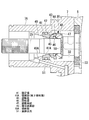
図2には、駆動部ハウジング7部分の内部構造の縦断面図が示されている。メカニカルシール30は、外周面にOリング42が嵌装され、内部側側面が摺動面43とされた環状の固定環41と、固定環41の摺動面43上を接触摺動する摺動突起45が外部側側面に設けられ、内周面にOリング46が嵌装された環状の回転環44と、回転環44を軸方向に移動可能に保持する保持器47と、保持器47と回転環44との間に介装されたバネ部材48とを備えている。
Next, the structure around the
FIG. 2 shows a longitudinal sectional view of the internal structure of the
駆動部ハウジング7のボス部7Aの内周面には、メカニカルシール30の固定環41を固定設置するための環状段差部49が設けられている。固定環41は、ボス部7Aの内部にその鍔付き側開口から挿入され、環状段差部49に当接されて軸方向に位置決め固定される。固定環41の外周面は、ボス部7Aの内周面に対してOリング42により気密にシールされる。一方、回転軸25の油ポンプ33の設置部よりも少し前端側には、外周の一部をカットした段付きの取り付け面50が設けられている。メカニカルシール30の回転環44および保持器47は、回転軸25に対して前端側から挿入され、保持器47が段付きの取り付け面50に嵌合されることによって、回転軸25の外周に軸方向に位置決めされて固定される。回転環44の内周面は、回転軸25の外周面に対してOリング46により気密にシールされる。
On the inner peripheral surface of the
メカニカルシール30を構成する固定環41と回転環44および保持器47とをそれぞれ上記のようにボス部7Aと回転軸25とに組み付け設置した状態で、駆動部ハウジング7のボス部7Aを、フロントハウジング6の前壁部8より突出されている回転軸25の前端部分に嵌め込み、駆動部ハウジング7をフロントハウジング6にボルトで固定することにより、固定環41の摺動面43と回転環43の摺動突起45とがバネ部材47によるバネ圧を受けた状態で接触される。これにより、固定環41と回転環44との間に接触摺動部が構成され、メカニカルシール30を介して回転軸25のハウジング2から外部側(大気側)への貫通部分が軸封される。
With the fixed
また、駆動部ハウジング7のボス部7Aには、環状段差部49の外部側にメカニカルシール30から漏出された潤滑油を図示省略の外部ドレンに導いて排出する油排出孔51が設けられている。さらに、環状段差部49の内周面および固定環41の内周面には、メカニカルシール30から漏出された潤滑油を固定環41の周辺で滞留させることなく、速やかに油排出孔51導き、外部に排出するための傾斜部49Aおよび41Aが設けられている。この傾斜部49A、41Aは、それぞれの内周面の内径が、ハウジングの内部側から外部側に向って漸次拡大するように連続的に設けられる。
The
しかして、本実施形態によれば、以下の作用効果を奏する。
メカニカルシール30は、固定環41がボス部7Aの内周面に固定設置され、回転環44が固定環41と対向されてその内部側に回転軸25の外周面に固定設置された構成とされているため、組み立て時には、駆動部ハウジング7のボス部7A内周面に固定されている固定環41の内周に、回転環44が固定されている回転軸25を嵌合することによって組み立てればよく、圧縮機の組み立てを容易化することができる。
Thus, according to the present embodiment, the following operational effects are obtained.
The
また、メカニカルシール30が設置されている位置の駆動部ハウジング7内の内部側は油溜り32であり、圧縮機運転中は冷媒を含む潤滑油で満たされている。このため、メカニカルシール30は、その外周面側全体が油溜り32内の潤滑油と接し、十分に潤滑されるとともに冷却されることになる。さらに、圧縮機運転中、メカニカルシール30の回転環44は回転軸25と共に回転され、摺動突起45が固定環41の摺動面43に接触摺動することにより両者間をシールしている。この際、接触摺動部に対して、油溜り32の潤滑油は回転環44の外周側から中心側に向って給油される。また、メカニカルシール30は、潤滑油により冷却されているとはいえ、摺動面43と摺動突起45との接触摺動によって固定環41および回転環44は発熱する。この発熱は、高圧冷媒の使用によって増大化する傾向にある。
Further, the inside of the
一方、固定環41と回転環44との間は、摺動面43と摺動突起45との接触摺動部によりシールされてはいるものの、時として極々微量の潤滑油が接触摺動部から漏出される場合がある。この潤滑油の漏出は、潤滑油が回転環44の外周側から中心側に向って給油されているため、固定環41の内周面側に漏出されることになる。この漏出油が固定環41の内周面周辺に滞留すると、上記した発熱による高温に晒され、スラッジ化して堆積するおそれがあるが、本実施形態では、固定環41の内周面および環状段差部49の内周面が、共に外部側に向って内径が拡大される傾斜部41A,49Aとされているため、漏出した潤滑油は両傾斜部41A,49Aに沿って外部側へと流出され、油排出孔51を通して外部に排出される。
On the other hand, the space between the fixed
このように、万一メカニカルシール30から微量の潤滑油が漏出しても、その潤滑油を傾斜部41A,49Aによって速やかに油排出孔51へと導き、外部に排出することができる。従って、漏出油が固定環41の周辺に滞留して高温に晒されることがなく、それがスラッジ化して堆積することにより発生する不具合、すなわちスラッジが接触摺動部に噛み込まれ、接触摺動部を損傷することに起因する軸封性の低下や潤滑油の漏出拡大等の不具合を解消することができる。特に、高圧冷媒の使用によって接触摺動部での発熱量が増加する傾向にあることから、漏出油のスラッジ化防止対策として有効である。
Thus, even if a small amount of lubricating oil leaks from the
なお、上記実施形態では、固定環41の内周面および環状段差部49の内周面の両方に傾斜部41A,49Aを設けた例について説明したが、かかる傾斜部は、固定環41の内周面および環状段差部49の内周面のいずれか一方だけに設けてもよく、このような構成にしても、上記とほぼ同等の効果を得ることができる。
また、傾斜部41A,49Aは、必ずしも固定環41の内周面および環状段差部49の内周面の全範囲に設ける必要はなく、少なくとも重力方向下側の一部だけに設けた構成とすることによっても、その目的を達成することができる。この場合、傾斜部41A,49Aは、例えば、固定環41の内周面および環状段差部49の内周面の重力方向下側の一部に軸線方向に沿う溝を設け、その溝の底面を外部側に向って漸次テーパー状に拡大するように形成して構成すればよい。
In the above-described embodiment, the example in which the
Further, the
[第2実施形態]
次に、本発明の第2実施形態について、図3を用いて説明する。
本実施形態は、上記した第1実施形態に対して、メカニカルシール30の固定環41の構成を部分的に変更している点が異なっている。その他の点については、第1実施形態と同様であるので説明は省略する。
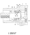
図3には、駆動部ハウジング7部分の内部構造の縦断面図が示されている。本実施形態では、回転環44に設けられる摺動突起45の内径D1と、固定環41の内周面の内径D2とが略等しくされている。この摺動突起45の内径D1と、固定環41の内周面の内径D2とは、好ましくは、(D1−D2)/D1≦0.07を満たすように設定される。
[Second Embodiment]
Next, a second embodiment of the present invention will be described with reference to FIG.
This embodiment is different from the first embodiment described above in that the configuration of the
FIG. 3 shows a longitudinal sectional view of the internal structure of the
上記の実施形態によると、回転環44の摺動突起45の内径D1と、固定環41の内周面の内径D2とが略等しくされていることから、接触摺動部から固定環41の内周面側に漏出された潤滑油が回転環44の摺動突起45と固定環41の内周面との間に溜まり込むことがなく、速やかに外部側へと流出され、油排出孔51から外部に排出される。
従って、本実施形態においても、上記第1実施形態と同様、メカニカルシール30からの漏出油が固定環41の周辺に滞留して高温に晒されることがなく、それがスラッジ化して堆積し、摺動面に噛み込まれることに起因する軸封性の低下および油の漏洩拡大を防止することができるという効果を奏する。
According to the above embodiment, the inner diameter D1 of the sliding
Therefore, also in the present embodiment, as in the first embodiment, the leaked oil from the
特に、摺動突起45の内径D1と固定環41の内周面の内径D2は、(D1−D2)/D1≦0.07を満たすため、回転環44の摺動突起45と固定環41の内周面との間に形成される凹み空間をほぼ無くすることができ、該凹み空間への漏出油の滞留を防止することができる。なお、図3においては、固定環41の内周面および環状段差部49の内周面がそれぞれ円筒面とされているが、固定環41の内周面および環状段差部49の内周面の全部または少なくとも重力方向下側の一部に、上記した第1実施形態と同様の傾斜部を設けた構成としてもよい。
In particular, the inner diameter D1 of the sliding
[第1参考例]
次に、本発明の第1参考例について、図4を用いて説明する。
本参考例は、上記した第1実施形態に対して、メカニカルシール30からの漏出油を油排出孔51に移送するための構成が異なる。その他の点については、第1実施形態と同様であるので説明は省略する。
本参考例は、図4に示されるように、回転軸25の外周面におけるメカニカルシール30の回転環44が固定設置されている位置よりも外部側から油排出孔51と対応する位置までの区間の全範囲または一部の範囲に、回転軸25の回転に伴いメカニカルシール30からの漏洩油を油排出孔51に向って移送する螺旋溝52を設けた構成を有する。
[First Reference Example]
Next, a first reference example of the present invention will be described with reference to FIG.
This reference example is different from the first embodiment in the configuration for transferring the leaked oil from the
In this reference example, as shown in FIG. 4, the section from the outer side to the position corresponding to the
上記の構成により、仮にメカニカルシール30の接触摺動部から固定環41の内周側に潤滑油が漏出されることがあっても、この漏出油を回転軸25に設けられている螺旋溝52によって、速やかに油排出孔51に向って移送し、油排出孔51から外部へと排出することができる。従って、本実施形態においても、メカニカルシール30からの漏出油が固定環41周辺に滞留して高温に晒されることがなく、それがスラッジ化して堆積し、接触摺動部に噛み込まれることによって発生する軸封性の低下や潤滑油の漏出拡大等の不具合を解消することができる。なお、上記した螺旋溝52は、溝ではなく、螺旋状の突起であってもよい。
Even if the lubricating oil leaks from the contact sliding portion of the
[第2参考例]
次に、本発明の第2参考例について、図4を用いて説明する。
本参考例は、上記した第1実施形態に対して、メカニカルシール30の固定環41周辺の温度上昇を抑制できるようにしている点が異なる。その他の点については、第1実施形態と同様であるので説明は省略する。
本参考例は、図4に示されるように、固定環41またはその設置部近傍に、温度センサ53を設け、この温度センサ53により検出される固定環41またはその設置部近傍の温度が設定温度以上になったとき、回転軸25の回転を停止または減速制御する構成とされている。なお、回転軸25の回転を停止するには、電磁クラッチ26をオフにすればよく、減速するには、外部駆動源の回転を減速すればよい。
[Second Reference Example]
Next, a second reference example of the present invention will be described with reference to FIG.
This reference example is different from the first embodiment described above in that the temperature rise around the
In this reference example, as shown in FIG. 4, a
上記の構成によれば、固定環41またはその設置部近傍の温度が設定温度以上になったとき、回転軸25の回転が停止または減速されるため、接触摺動部での発熱による固定環41周辺の温度上昇を抑制することができる。従って、接触摺動部から潤滑油が漏出することがあっても、漏出油が固定環周辺に滞留して高温に晒されることがなく、それがスラッジ化して堆積し、接触摺動部に噛み込まれることにより発生する軸封性の低下や潤滑油の漏出拡大等の不具合を解消することができるという効果を得ることができる。
According to the above configuration, when the temperature in the vicinity of the
[第3参考例]
次に、本発明の第3参考例について、図4を用いて説明する。
本参考例は、上記した第1実施形態に対して、メカニカルシール30の固定環41周辺の温度上昇を抑制する手段を備えて点が異なる。その他の点については、第1実施形態と同様であるので説明は省略する。
本参考例は、図4に示されるように、メカニカルシール30の固定環41の外部側空間に、外部空気を送風して固定環41および回転環44を冷却する冷却手段54を設けた構成とされる。この冷却手段54は、回転軸25の外周に複数枚の送風羽根54Aを設けて構成することができる。
[Third reference example]
Next, a third reference example of the present invention will be described with reference to FIG.
This reference example differs from the first embodiment described above in that it includes means for suppressing a temperature rise around the
As shown in FIG. 4, the present reference example has a configuration in which a cooling means 54 that cools the
上記の構成により、メカニカルシール30の外部側から固定環41および回転環44に低温の外気を送風して、固定環41および回転環44を強制的に冷却し、接触摺動部での発熱による固定環41周辺の温度上昇を抑制することができる。従って、本実施形態においても、メカニカルシール30からの漏出油が固定環周辺に滞留して高温に晒されることがなく、それがスラッジ化して堆積し、接触摺動部に噛み込まれることにより発生する軸封性の低下や潤滑油の漏出拡大等の不具合を解消することができるという効果を奏する。また、冷却手段54は、回転軸25に送風羽根54Aを取り付けるだけで簡単に構成することができる。
With the above configuration, low temperature outside air is blown from the outside of the
[第4参考例]
次に、本発明の第4参考例について、図4を用いて説明する。
本参考例は、上記した第1実施形態に対して、メカニカルシール30の固定環41周辺の温度上昇を抑制する手段を備えて点が異なる。その他の点については、第1実施形態と同様であるので説明は省略する。
本参考例は、図4に示されるように、固定環41の反回転環側側面および/または内周面に冷却フィン55を一体または別体に設けて構成される。なお、図4には、固定環41の反回転環側側面に別体の冷却フィン55を設けた例が図示されている。
[Fourth Reference Example]
Next, a fourth reference example of the present invention will be described with reference to FIG.
This reference example differs from the first embodiment described above in that it includes means for suppressing a temperature rise around the
As shown in FIG. 4, the present reference example is configured by providing cooling fins 55 integrally or separately on the side surface and / or the inner peripheral surface of the
上記の構成により、固定環41の発熱をその側面および/または内周面に設けられている冷却フィン55により外部側に放熱し、固定環41周辺の温度上昇を抑制することができる。従って、本実施形態においても、メカニカルシール30からの漏出油が固定環周辺に滞留して高温に晒されることがなく、それがスラッジ化して堆積し、接触摺動部に噛み込まれることにより発生する軸封性の低下や潤滑油の漏出拡大等の不具合を解消することができる。
With the above configuration, the heat generation of the
[第3実施形態]
次に、本発明の第3実施形態について、図5を用いて説明する。
本参考例は、上記した第1実施形態に対して、油排出孔51の構成が異なる。その他の点については、第1実施形態と同様であるので説明は省略する。
図5は、駆動部ハウジング7のボス部7Aの縦断面図である。駆動部ハウジング7のボス部7Aの内周側には、上記したように、環状段差部49が設けられており、この環状段差部49の内周面には、全周にわたり傾斜部49Aが設けられている。また、ボス部7Aには、環状段差部49の外部側にメカニカルシール30からの漏出油を外部の油ドレンに導いて、外部に排出するための油排出孔51が穿設されている。
[Third Embodiment]
Next, a third embodiment of the present invention will be described with reference to FIG.
This reference example differs from the first embodiment described above in the configuration of the
FIG. 5 is a longitudinal sectional view of the
本実施形態では、この油排出孔51の開口51Aを、環状段差部49の内周面における傾斜部49Aの途中に設けている。このように油排出孔51の開口51Aを傾斜部49Aの途中に設けることにより、回転軸25の回転による遠心力の影響を受けながら環状段差部49内の傾斜部49Aを伝って外部方向へと移動しているメカニカルシール30からの漏出油を、そのまま傾斜部49Aに開口51Aが設けられている油排出孔51へと直に排出することができる。従って、漏出油の滞留時間を一段と短縮化し、より速やかに外部へと排出することができる。
In the present embodiment, the
なお、本発明は、上記実施形態にかかる発明に限定されるものではなく、その要旨を逸脱しない範囲において、適宜変形が可能である。例えば、上記実施形態では、メカニカルシール30の内部側に油溜り空間を設けた例について説明したが、この空間がミスト潤滑油を含む冷媒雰囲気空間とされるものであってもよい。また、メカニカルシール30の固定環41および回転環44に設けられる摺動面43および摺動突起45により構成される接触摺動部は、これに限らず、摺動面を回転環に、摺動突起を固定環に設ける等、他の構成としてもよい。さらに、上記各実施形態を適宜組み合わせて用いてもよい。
In addition, this invention is not limited to the invention concerning the said embodiment, In the range which does not deviate from the summary, it can change suitably. For example, in the above-described embodiment, an example in which an oil reservoir space is provided on the inner side of the
1 スクロール圧縮機(冷媒圧縮機)
2 ハウジング
7 駆動部ハウジング
7A ボス部
25 回転軸
30 メカニカルシール
41 固定環
41A 傾斜部(第2傾斜部)
43 摺動面
44 回転環
45 摺動突起
49 環状段差部
49A 傾斜部
51 油排出孔
51A 開口
D1 摺動突起の内径
D2 固定環の内径
1 Scroll compressor (refrigerant compressor)
2
43 Sliding
Claims (6)
前記メカニカルシールは、前記ボス部の内周面に固定設置されている固定環と、該固定環の内部側に該固定環と対向されて前記回転軸の外周面に固定設置され、前記固定環との互いに対向する側面間に接触摺動部を形成する回転環とを備え、
前記固定環よりも外部側の前記ボス部の内周面に環状段差部が設けられ、該環状段差部の内部側に前記固定環が固定設置されているとともに、該環状段差部の内周面の全部または少なくとも重力方向下側の一部に前記固定環側からその外部側の前記油排出孔に向って漸次径が拡大する傾斜部が設けられていることを特徴とする冷媒圧縮機。 Between the inner peripheral surface of the boss portion of the housing through which the rotating shaft passes and the outer peripheral surface of the rotating shaft, a mechanical seal is installed to seal the inner side and the outer side of the housing, and the boss portion In the refrigerant compressor provided with an oil discharge hole for discharging leaked oil to the outside of the mechanical seal of the
The mechanical seal is fixedly installed on the inner peripheral surface of the boss portion, and is fixedly installed on the outer peripheral surface of the rotating shaft so as to face the fixed ring on the inner side of the fixed ring. And a rotating ring that forms a contact sliding portion between side surfaces facing each other,
An annular step portion is provided on the inner peripheral surface of the boss portion outside the fixed ring, the fixed ring is fixedly installed on the inner side of the annular step portion, and the inner peripheral surface of the annular step portion. The refrigerant compressor is characterized in that an inclined portion whose diameter gradually increases from the stationary ring side toward the oil discharge hole on the outer side thereof is provided in all or at least a part on the lower side in the gravity direction.
前記メカニカルシールは、前記ボス部の内周面に固定設置されている固定環と、該固定環の内部側に該固定環と対向されて前記回転軸の外周面に固定設置され、前記固定環との互いに対向する側面間に接触摺動部を形成する回転環とを備え、
前記固定環よりも外部側の前記ボス部の内周面に環状段差部が設けられ、該環状段差部の内径が前記固定環の内径よりも大きくされているとともに、該環状段差部の内周面の全部または少なくとも重力方向下側の一部に前記固定環側からその外部側の前記油排出孔に向って漸次径が拡大する傾斜部が設けられていることを特徴とする冷媒圧縮機。 Between the inner peripheral surface of the boss portion of the housing through which the rotating shaft passes and the outer peripheral surface of the rotating shaft, a mechanical seal is installed to seal the inner side and the outer side of the housing, and the boss portion In the refrigerant compressor provided with an oil discharge hole for discharging leaked oil to the outside of the mechanical seal of the
The mechanical seal is fixedly installed on the inner peripheral surface of the boss portion, and is fixedly installed on the outer peripheral surface of the rotating shaft so as to face the fixed ring on the inner side of the fixed ring. And a rotating ring that forms a contact sliding portion between side surfaces facing each other,
An annular step portion is provided on the inner peripheral surface of the boss portion outside the fixed ring, and the inner diameter of the annular step portion is larger than the inner diameter of the fixed ring, and the inner periphery of the annular step portion A refrigerant compressor characterized in that an inclined portion whose diameter gradually increases from the stationary ring side toward the oil discharge hole on the outer side of the entire surface or at least part of the lower side in the gravitational direction is provided.
Priority Applications (4)
| Application Number | Priority Date | Filing Date | Title |
|---|---|---|---|
| JP2007191085A JP5455294B2 (en) | 2007-07-23 | 2007-07-23 | Refrigerant compressor |
| EP08791423.0A EP2284396B1 (en) | 2007-07-23 | 2008-07-22 | Refrigerant compressor |
| PCT/JP2008/063142 WO2009014124A1 (en) | 2007-07-23 | 2008-07-22 | Refrigerant compressor |
| US12/443,537 US8257063B2 (en) | 2007-07-23 | 2008-07-22 | Refrigerant compressor |
Applications Claiming Priority (1)
| Application Number | Priority Date | Filing Date | Title |
|---|---|---|---|
| JP2007191085A JP5455294B2 (en) | 2007-07-23 | 2007-07-23 | Refrigerant compressor |
Publications (2)
| Publication Number | Publication Date |
|---|---|
| JP2009024666A JP2009024666A (en) | 2009-02-05 |
| JP5455294B2 true JP5455294B2 (en) | 2014-03-26 |
Family
ID=40281375
Family Applications (1)
| Application Number | Title | Priority Date | Filing Date |
|---|---|---|---|
| JP2007191085A Active JP5455294B2 (en) | 2007-07-23 | 2007-07-23 | Refrigerant compressor |
Country Status (4)
| Country | Link |
|---|---|
| US (1) | US8257063B2 (en) |
| EP (1) | EP2284396B1 (en) |
| JP (1) | JP5455294B2 (en) |
| WO (1) | WO2009014124A1 (en) |
Families Citing this family (20)
| Publication number | Priority date | Publication date | Assignee | Title |
|---|---|---|---|---|
| US9549585B2 (en) | 2008-06-13 | 2017-01-24 | Nike, Inc. | Footwear having sensor system |
| JP5925490B2 (en) | 2008-06-13 | 2016-05-25 | ナイキ イノベイト セー. フェー. | Footwear with sensor system |
| US10070680B2 (en) | 2008-06-13 | 2018-09-11 | Nike, Inc. | Footwear having sensor system |
| US8831407B2 (en) | 2010-11-10 | 2014-09-09 | Nike, Inc. | Systems and methods for time-based athletic activity measurement and display |
| CN112545101B (en) | 2011-02-17 | 2022-05-03 | 耐克创新有限合伙公司 | Footwear with sensor system |
| KR101767794B1 (en) | 2011-02-17 | 2017-08-11 | 나이키 이노베이트 씨.브이. | Location mapping |
| CN103476335B (en) | 2011-02-17 | 2017-06-09 | 耐克创新有限合伙公司 | Footwear with sensing system |
| JP5573825B2 (en) * | 2011-12-06 | 2014-08-20 | 株式会社デンソー | Rotating machine |
| US20130213147A1 (en) | 2012-02-22 | 2013-08-22 | Nike, Inc. | Footwear Having Sensor System |
| US11071344B2 (en) | 2012-02-22 | 2021-07-27 | Nike, Inc. | Motorized shoe with gesture control |
| US11684111B2 (en) | 2012-02-22 | 2023-06-27 | Nike, Inc. | Motorized shoe with gesture control |
| US9743861B2 (en) | 2013-02-01 | 2017-08-29 | Nike, Inc. | System and method for analyzing athletic activity |
| US10926133B2 (en) | 2013-02-01 | 2021-02-23 | Nike, Inc. | System and method for analyzing athletic activity |
| US11006690B2 (en) | 2013-02-01 | 2021-05-18 | Nike, Inc. | System and method for analyzing athletic activity |
| US9410857B2 (en) | 2013-03-15 | 2016-08-09 | Nike, Inc. | System and method for analyzing athletic activity |
| CN103234044A (en) * | 2013-05-13 | 2013-08-07 | 方高云 | Shaft seal of oil seal machinery |
| EP3625485B1 (en) * | 2017-05-18 | 2022-02-23 | Sulzer Management AG | A mechanical seal and a slide ring thereof |
| JP7265843B2 (en) * | 2018-07-13 | 2023-04-27 | ナブテスコ株式会社 | Clutch device and braking device |
| US11692466B2 (en) | 2019-05-30 | 2023-07-04 | Pratt & Whitney Canada Corp. | Machine having a liquid lubrication system and a shaft |
| US11603842B2 (en) | 2019-08-14 | 2023-03-14 | Pratt & Whitney Canada Corp. | Method of priming a pump of an aircraft engine |
Family Cites Families (11)
| Publication number | Priority date | Publication date | Assignee | Title |
|---|---|---|---|---|
| JPS619674U (en) | 1984-06-22 | 1986-01-21 | 石川島播磨重工業株式会社 | Shaft sealing device |
| JPS63130679U (en) * | 1987-02-19 | 1988-08-26 | ||
| JP2573746Y2 (en) * | 1992-12-07 | 1998-06-04 | サンデン株式会社 | Mechanical seal oil leakage prevention mechanism of open type compressor |
| JPH09105382A (en) | 1995-10-09 | 1997-04-22 | Toyota Autom Loom Works Ltd | Compressor |
| JPH11351146A (en) * | 1998-06-04 | 1999-12-21 | Toyota Autom Loom Works Ltd | Compressor |
| US6632077B2 (en) * | 2002-01-11 | 2003-10-14 | Carrier Corporation | Hybrid bearing arrangement for centrifugal compressor |
| JP4219649B2 (en) | 2002-10-18 | 2009-02-04 | リックス株式会社 | Rotary joint |
| JP2006242061A (en) | 2005-03-02 | 2006-09-14 | Valeo Thermal Systems Japan Corp | Mechanical seal structure for compressor |
| JP2007040214A (en) * | 2005-08-04 | 2007-02-15 | Calsonic Compressor Inc | Rotary gas compressor |
| JP4692820B2 (en) * | 2005-08-11 | 2011-06-01 | 株式会社Ihi | Supercharger with electric motor |
| JP2009013966A (en) * | 2007-07-09 | 2009-01-22 | Ihi Corp | Supercharger with electric motor |
-
2007
- 2007-07-23 JP JP2007191085A patent/JP5455294B2/en active Active
-
2008
- 2008-07-22 EP EP08791423.0A patent/EP2284396B1/en active Active
- 2008-07-22 US US12/443,537 patent/US8257063B2/en active Active
- 2008-07-22 WO PCT/JP2008/063142 patent/WO2009014124A1/en active Application Filing
Also Published As
| Publication number | Publication date |
|---|---|
| JP2009024666A (en) | 2009-02-05 |
| US8257063B2 (en) | 2012-09-04 |
| EP2284396A1 (en) | 2011-02-16 |
| EP2284396A4 (en) | 2015-08-26 |
| WO2009014124A1 (en) | 2009-01-29 |
| EP2284396B1 (en) | 2017-08-09 |
| US20100111705A1 (en) | 2010-05-06 |
Similar Documents
| Publication | Publication Date | Title |
|---|---|---|
| JP5455294B2 (en) | Refrigerant compressor | |
| JP5197157B2 (en) | Screw fluid machine | |
| JP5197141B2 (en) | Two-stage screw compressor and refrigeration system | |
| US7762724B2 (en) | Compressor bearing | |
| US20070077159A1 (en) | Scroll fluid machine | |
| KR100675548B1 (en) | Compressor | |
| JP4833882B2 (en) | Screw fluid machine | |
| JP5348924B2 (en) | Screw fluid machine | |
| JP2008303781A (en) | Screw compressor | |
| EP3276173A1 (en) | Refrigerant shaft seal and open refrigerant compressor equipped with refrigerant shaft seal | |
| JP2008121479A (en) | Hermetic screw compressor | |
| JP2008232005A (en) | Screw compressor | |
| US20020182097A1 (en) | Oil leak Prevention Structure for vacuum pump | |
| KR101886668B1 (en) | Scroll fluid machine | |
| JP2010001835A (en) | Gas compressor | |
| JP2009257337A (en) | Scroll type fluid machine | |
| JP2020148139A (en) | Open type compressor | |
| JP6058512B2 (en) | Scroll type fluid machine | |
| JP2009041576A (en) | Scroll type compressor | |
| JP2007040214A (en) | Rotary gas compressor | |
| JP2006242061A (en) | Mechanical seal structure for compressor | |
| JP2005139977A (en) | Scroll type fluid machine | |
| JP2007327339A (en) | Gas compressor | |
| JPS61164095A (en) | Rotary compressor | |
| JP2009257131A (en) | Lubricating agent supplying structure for compressor |
Legal Events
| Date | Code | Title | Description |
|---|---|---|---|
| A621 | Written request for application examination |
Free format text: JAPANESE INTERMEDIATE CODE: A621 Effective date: 20100604 |
|
| A131 | Notification of reasons for refusal |
Free format text: JAPANESE INTERMEDIATE CODE: A131 Effective date: 20120807 |
|
| A521 | Written amendment |
Free format text: JAPANESE INTERMEDIATE CODE: A523 Effective date: 20121009 |
|
| A131 | Notification of reasons for refusal |
Free format text: JAPANESE INTERMEDIATE CODE: A131 Effective date: 20130409 |
|
| A521 | Written amendment |
Free format text: JAPANESE INTERMEDIATE CODE: A523 Effective date: 20130610 |
|
| TRDD | Decision of grant or rejection written | ||
| A01 | Written decision to grant a patent or to grant a registration (utility model) |
Free format text: JAPANESE INTERMEDIATE CODE: A01 Effective date: 20131210 |
|
| A61 | First payment of annual fees (during grant procedure) |
Free format text: JAPANESE INTERMEDIATE CODE: A61 Effective date: 20140107 |
|
| R151 | Written notification of patent or utility model registration |
Ref document number: 5455294 Country of ref document: JP Free format text: JAPANESE INTERMEDIATE CODE: R151 |