JP5680962B2 - 軸貫通非接触の多回転絶対位置磁気センサ - Google Patents
軸貫通非接触の多回転絶対位置磁気センサ Download PDFInfo
- Publication number
- JP5680962B2 JP5680962B2 JP2010517448A JP2010517448A JP5680962B2 JP 5680962 B2 JP5680962 B2 JP 5680962B2 JP 2010517448 A JP2010517448 A JP 2010517448A JP 2010517448 A JP2010517448 A JP 2010517448A JP 5680962 B2 JP5680962 B2 JP 5680962B2
- Authority
- JP
- Japan
- Prior art keywords
- sensor
- magnet
- detection system
- shaft
- absolute position
- Prior art date
- Legal status (The legal status is an assumption and is not a legal conclusion. Google has not performed a legal analysis and makes no representation as to the accuracy of the status listed.)
- Expired - Fee Related
Links
Images


Classifications
-
- G—PHYSICS
- G01—MEASURING; TESTING
- G01D—MEASURING NOT SPECIALLY ADAPTED FOR A SPECIFIC VARIABLE; ARRANGEMENTS FOR MEASURING TWO OR MORE VARIABLES NOT COVERED IN A SINGLE OTHER SUBCLASS; TARIFF METERING APPARATUS; MEASURING OR TESTING NOT OTHERWISE PROVIDED FOR
- G01D5/00—Mechanical means for transferring the output of a sensing member; Means for converting the output of a sensing member to another variable where the form or nature of the sensing member does not constrain the means for converting; Transducers not specially adapted for a specific variable
- G01D5/12—Mechanical means for transferring the output of a sensing member; Means for converting the output of a sensing member to another variable where the form or nature of the sensing member does not constrain the means for converting; Transducers not specially adapted for a specific variable using electric or magnetic means
- G01D5/244—Mechanical means for transferring the output of a sensing member; Means for converting the output of a sensing member to another variable where the form or nature of the sensing member does not constrain the means for converting; Transducers not specially adapted for a specific variable using electric or magnetic means influencing characteristics of pulses or pulse trains; generating pulses or pulse trains
- G01D5/245—Mechanical means for transferring the output of a sensing member; Means for converting the output of a sensing member to another variable where the form or nature of the sensing member does not constrain the means for converting; Transducers not specially adapted for a specific variable using electric or magnetic means influencing characteristics of pulses or pulse trains; generating pulses or pulse trains using a variable number of pulses in a train
- G01D5/2454—Encoders incorporating incremental and absolute signals
- G01D5/2458—Encoders incorporating incremental and absolute signals with incremental and absolute tracks on separate encoders
-
- G—PHYSICS
- G01—MEASURING; TESTING
- G01B—MEASURING LENGTH, THICKNESS OR SIMILAR LINEAR DIMENSIONS; MEASURING ANGLES; MEASURING AREAS; MEASURING IRREGULARITIES OF SURFACES OR CONTOURS
- G01B7/00—Measuring arrangements characterised by the use of electric or magnetic techniques
- G01B7/003—Measuring arrangements characterised by the use of electric or magnetic techniques for measuring position, not involving coordinate determination
-
- B—PERFORMING OPERATIONS; TRANSPORTING
- B62—LAND VEHICLES FOR TRAVELLING OTHERWISE THAN ON RAILS
- B62D—MOTOR VEHICLES; TRAILERS
- B62D1/00—Steering controls, i.e. means for initiating a change of direction of the vehicle
-
- B—PERFORMING OPERATIONS; TRANSPORTING
- B62—LAND VEHICLES FOR TRAVELLING OTHERWISE THAN ON RAILS
- B62D—MOTOR VEHICLES; TRAILERS
- B62D1/00—Steering controls, i.e. means for initiating a change of direction of the vehicle
- B62D1/02—Steering controls, i.e. means for initiating a change of direction of the vehicle vehicle-mounted
- B62D1/16—Steering columns
-
- B—PERFORMING OPERATIONS; TRANSPORTING
- B62—LAND VEHICLES FOR TRAVELLING OTHERWISE THAN ON RAILS
- B62D—MOTOR VEHICLES; TRAILERS
- B62D15/00—Steering not otherwise provided for
- B62D15/02—Steering position indicators ; Steering position determination; Steering aids
- B62D15/021—Determination of steering angle
- B62D15/0245—Means or methods for determination of the central position of the steering system, e.g. straight ahead position
-
- B—PERFORMING OPERATIONS; TRANSPORTING
- B62—LAND VEHICLES FOR TRAVELLING OTHERWISE THAN ON RAILS
- B62D—MOTOR VEHICLES; TRAILERS
- B62D21/00—Understructures, i.e. chassis frame on which a vehicle body may be mounted
-
- B—PERFORMING OPERATIONS; TRANSPORTING
- B62—LAND VEHICLES FOR TRAVELLING OTHERWISE THAN ON RAILS
- B62D—MOTOR VEHICLES; TRAILERS
- B62D47/00—Motor vehicles or trailers predominantly for carrying passengers
-
- G—PHYSICS
- G01—MEASURING; TESTING
- G01D—MEASURING NOT SPECIALLY ADAPTED FOR A SPECIFIC VARIABLE; ARRANGEMENTS FOR MEASURING TWO OR MORE VARIABLES NOT COVERED IN A SINGLE OTHER SUBCLASS; TARIFF METERING APPARATUS; MEASURING OR TESTING NOT OTHERWISE PROVIDED FOR
- G01D2205/00—Indexing scheme relating to details of means for transferring or converting the output of a sensing member
- G01D2205/20—Detecting rotary movement
- G01D2205/26—Details of encoders or position sensors specially adapted to detect rotation beyond a full turn of 360°, e.g. multi-rotation
Description
たとえば、特許文献2または特許文献3に記載の光学的な解決法は複雑で高価であり、また、温度条件や環境条件と適合しないため、モータコンパートメントへの組み込みに適合しないことが分かる。
電位差測定による解決法は、主にコストと単純性の面で利点が大きい。
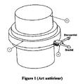
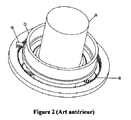
は、略直径方向に磁化された磁石リングまたは磁気ディスクの角度位置を決定するために磁石感知センサを用いる360°回転位置センサが記載されている。この特許文献において、磁石によって生成された磁界の方向を感知するセンサは磁石の外側に配置され、これによって、たとえばステアリングコラムの回転角測定用の軸貫通回転センサが得られる。また特許文献13においては、センサにおける回転を複数回から1回以下に抑えるために、運動の減速に関連付けたセンサが使用されている(図2参照)。この解決法の主な不利点は、分解能および精度を同様に低減するn減速比を用いることに起因している。これは、精度および分解能が非常に高いステアリングコラムの用途には不十分な場合がある。
第1センサ(メインセンサとも言う)は、360°を越える軌跡においてハンドル角度を測定し、この軌跡における該角度に比例する信号を伝達する。それ以上の角度については、伝達される信号は、同一のモジュロ(modulo)360°角に対して伝達される信号と同じである。この信号のみでは、初期位置に対する相対的なハンドル位置は分かるが、絶対位置は分からない。実際、第1センサは360°周期の周期信号を伝達する。この周期内の角度は正確に測定されるが、シャフトが何周期にあるかは分からない。
特許文献11には、インクリメント式の第2信号を生成する方法(ジェネバ駆動)が記載されている。この信号は第1センサが何回転にあるかを正確に示すが、(インクリメント値を用いて)不連続であるため、ユーザはこの信号を使用して冗長性を得ることはできない。
第2センサの信号は軌跡全体における入力軸の角度に略比例するが、センサ1の信号よりは精度が劣る。
有利なことに、両信号を電子的に組み合わせることによって、軌跡全体における入力軸位置に比例する、信号2と同種であるが第1信号の精度を有する信号を合成することができる。このため、精度および分解能において有意な利点がある。
ホイールおよびウォームの減速;
ギアトレーンの減速;
ギアホイールの直接的な減速:この解決法は可能であるが、寸法の点からは有利でない;
磁気トルクによる減速。
:ブリーチに取り付けら放射状に磁化された複数の磁石を含み、トルクセンサに属する、第1のロータ磁気構造と;複数の歯を有する2つの同心リングを含み、トルクセンサに属する、第2のステータ磁気構造と;磁石感知要素が配置される測定間隙を形成すべく、閉鎖アームによって拡張された2つの同心リング部分からなり、トルクセンサに属する、第3の固定コレクタと;ステータ部分のリング間に配置され直径方向に磁化された磁石(またはハルバッハ磁石)を含み、トルクセンサの第2の磁気構造を支持するプラスチック部分の上におけるキャストから成形可能である、第4の構造と、である。MLX90316または他の種類の磁石感知要素は、位置磁石センサの外部に配置され、トルクセンサの磁石感知要素と同じPCBに属する。
有利な方法において、1つのハウジング内に統合するために、両検出システムは互いに近接して配置される。このため装置はコンパクトとなり、監視を行う装置に容易に載置できる。
図10は本発明の出力信号を示す。第1信号は高精度の分解能の360°(1回転)における周期信号であり、第2信号はこの周期信号の4分の1の分解能の4回転における絶対信号である。
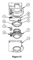
大口径のウォーム1は、測定されるシャフト(たとえば、自動車のステアリングコラム
)周囲に搭載されるように、中が空洞になっている。このウォームは測定されるシャフトに取り付けられている。直径方向に磁化された第1磁石3は、このウォームに連結され、1回転を通じて精密信号を感知する第1センサの一部を成す。この磁石は、磁気ブリーチ8に搭載されてもされなくてもよい。本出願において、ウォームはセンサハウジング9に軸留めされ、ハウジングは固定されている。このウォームは、第2磁石7が連結されるスプロケット4を回転させるように駆動する。第2磁気センサの一部は、精度は劣るが軌跡全体にわたる信号を感知する(図10の信号n°2)。このスプロケットは、ハウジング9に軸留めされている。自動車ハンドルの角度軌跡は、多くの場合2〜5回転分であるが、これらの値に限らない。回転ポインタである磁石7が軌跡全体において1回転にわずかに満たない回転をするように、減速比が選択される。この角度軌跡は、分解能の点で、第2センサの可能性から最も利点が得られるものである。図に示す例において、ウォーム1には3つの溝があり、スプロケット4には13個の歯がある。したがって、減速比は4.33であり、これは軌跡が4回転のハンドルに適合する。この運動変換においてわずかな緩みは許容されるが、不可避な程度にすべきであり、減速時の緩みに関係する寄生ヒステリシスを追加することによって第2センサの精度を過度に低下させないようにすべきである。
センサ6は、直径方向に磁化された磁石7の軸方向成分および接線成分を測定する。
中空の第1ホイール1はシャフトに連結されており、その角度位置が測定される必要がある。このシャフトは、ホイール1を貫通する。
第2磁石7は粗い第2信号(図10、信号n°2)のセンサの一部であるが、軌跡全体にわたって拡張される。
可動部の数は、大きさの制約または所要の軌跡に適合するように変更してもよい。
入力ホイール1(歯数:60)
ホイール12(歯数:12,34)
ホイール13(歯数:12,39)
出力ホイール14(歯数:35)。
図20は、直接的な磁気接続の使用を示す。
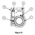
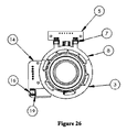
2ステータ多極磁石10と、2つのコレクタ8と、PCB5に搭載された2つの磁石感知要素7とを備えるトルクセンサ;と、
アセンブリの大きさを最適にするために2つのステータ間に適切に配置され、直径方向に磁化された磁石3と、PCB5上に配置され、磁石3の軸方向成分および接線成分を測定するセンサ6とを含む位置センサ;と
に再編成される。磁石3はステータと同時にキャスト成形することができ、トルクおよび位置の測定は、磁石感知要素を用いて同一面で行える。
図24、図25、および図26は、トルクセンサと多回転絶対位置センサとのアセンブリの斜視図、断面図、および正面図である。このアセンブリは以下のように再編成される
。
周期θ/nの「周期」関数に従って信号を生成して周期的な角度位置を提供する検出システムであって、アセンブリの大きさを最適にするために2つのステータ間に適切に配置される直径方向に磁化された磁石3と、PCB5上に配置され、磁石3の軸方向成分および接線成分を測定するセンサ6とを含む検出システム、
軌跡θにおける絶対信号を生成する検出システムであって、直径方向に磁化された磁石19と磁石19の軸方向成分および接線成分を測定するセンサ16とを含む、ホイール18およびウォーム11の減速機(図11〜図15を参照)を含む検出システム。
図11〜図19に顕著に見られるように、1つのハウジングに組み付けられたコンパクトなセンサを実現するために、両検出システム(すなわち、センサ2,6)は互いに接近して有意に配置される。
Claims (17)
- シャフトの軌跡θにおける角度位置を測定するための絶対位置磁気センサであって、前記シャフトは前記センサを貫通しており、前記センサは前記シャフトの位置を検出するための少なくとも2つの検出システムを備え、
前記検出システムのうちの少なくとも第1の検出システムは、前記シャフトに連結される入力軸の運動を連続的に変換し、周期θ/nの「周期」関数に従って信号を生成して前記シャフトの周期的な角度位置を提供するための機械的システムを含み、前記第1の検出システムは、直径方向に磁化されている第1の磁石を備え、前記第1の磁石は前記シャフトの周囲に取り付けられる中空のウォームに連結されており、
前記検出システムのうちの少なくとも第2の検出システムは、前記シャフトの軌跡θにおける絶対信号を生成するためのシステムを含み、前記第2の検出システムは、スプロケットに連結される第2の磁石を備え、前記ウォームは前記スプロケットを回転させるように駆動し、
前記第1の検出システムは、位相が略90度ずれた2つの正弦波信号を供給するために、磁石によって生成される磁界の動径成分と、接線成分とを測定する、略同位置に配置された少なくとも2つの磁石感知要素を含み、
θおよびnは、θ/n=360(n>1)の関係を満たし、
前記第2の検出システムは、位相が略90度ずれた2つの正弦波信号を供給するために、磁界の接線成分、動径成分、または軸方向成分と、磁界の動径成分、軸方向成分、または接線成分とを測定する、略同位置に配置された少なくとも2つの磁石感知要素を含み、
前記第1、第2の検出システムの2つのセンサは共に、1つの印刷回路基板上に配置される、絶対位置磁気センサ。 - 前記第2の検出システムは、前記第1の検出システムの出力軸上の少なくとも1つの磁石を含むとともに、少なくとも1つの磁石感知要素を含む、請求項1に記載の絶対位置磁気センサ。
- 前記第1の検出システムの磁石感知要素と、前記第2の検出システムの1つ以上の磁石感知要素とは、同一平面上にある、請求項1に記載の絶対位置磁気センサ。
- 前記磁石感知要素は、同一の接続平面に接続される、請求項3に記載の絶対位置磁気センサ。
- 前記第1の検出システムは、ホイールまたはウォームの減速機である、請求項3に記載の絶対位置磁気センサ。
- 前記第1の検出システムは、少なくとも2つの多極磁石を備える非接触減速機であり、前記多極磁石のうちの少なくとも1つは前記シャフトに連結されている、請求項3に記載の絶対位置磁気センサ。
- 前記シャフトに連結された前記減速機の多極磁石は、前記第1の検出システムの磁石でもある、請求項5に記載の絶対位置磁気センサ。
- 前記第1の検出システムに連結された前記減速機の多極磁石は、前記第2の検出システムの磁石でもある、請求項6に記載の絶対位置磁気センサ。
- 信号を処理する回路は、前記第1および第2の検出システムからの電気信号を用いて、前記シャフトの軌跡θ全体における絶対位置を高精度に計算する、請求項1に記載の絶対位置磁気センサ。
- 前記第1および第2の検出システムは、1つのハウジングに組み込まれるように互いに接近して配置される、請求項1に記載の絶対位置磁気センサ。
- ステアリングコラムのねじれ検出用の位置センサのアセンブリであって、
トーションバーにかかるねじれトルクを推定するために、トーションバーによって同軸に接続された入力軸および出力軸の相対的角度位置±Ψ(Ψ>20)を検出するための少なくとも1つの検出システムと、同検出システムは、放射状に配向された複数の磁石を含む第1のロータ磁気構造と、近傍に少なくとも1つの磁石感知要素が配置された歯によって拡張される2つのリングを含む第2のステータ構造とからなることと;
請求項1乃至10のいずれか一項に記載の絶対位置磁気センサにおける第2の検出システムと;
少なくとも1つの信号処理システムと、を含み、
θ、Ψ、およびnは、θ/n=360(θ/Ψ>20、n≧1)の関係を満たし;
前記シャフトは、トルクセンサの入力軸または出力軸でもある、アセンブリ。 - 前記トルクセンサは、少なくとも1つの間隙を形成する2つのフロー閉鎖部から成る第3の固定コレクタ構造を含み、前記間隙には、少なくとも1つの磁石感知要素が配置される、請求項11に記載のアセンブリ。
- 前記トルクセンサのフロー閉鎖部、およびステータリングは、互いの間において、ステータ表面およびコレクタ表面の両方の径方向の相対位置から独立した一定な位置に収集表面を形成する、請求項12に記載のアセンブリ。
- 請求項1乃至10のうちのいずれか一項に記載の絶対位置磁気センサを含む、請求項11に記載のアセンブリ。
- 前記第1の検出システムの磁石感知要素と、前記第2の検出システムの1つ以上の磁石感知要素とのうちの1つ以上は、ねじれ検出用の前記センサの磁石感知要素と同一平面上にある、請求項11に記載のアセンブリ。
- 少なくとも1つのシールドが、ねじれ測定用の前記センサと前記シャフトの位置検出システムとの間に組み込まれる、請求項11に記載のアセンブリ。
- トルクおよび位置センサの磁気サブアセンブリはキャスト成形される、請求項11に記載のアセンブリ。
Applications Claiming Priority (3)
| Application Number | Priority Date | Filing Date | Title |
|---|---|---|---|
| FR0705373 | 2007-07-24 | ||
| FR0705373A FR2919385B1 (fr) | 2007-07-24 | 2007-07-24 | Capteur magnetique sans contact de position absolue multitour a arbre traversant |
| PCT/FR2008/001093 WO2009047401A2 (fr) | 2007-07-24 | 2008-07-23 | Capteur magnétique sans contact de position absolue multitour à arbre traversant |
Related Child Applications (1)
| Application Number | Title | Priority Date | Filing Date |
|---|---|---|---|
| JP2014238646A Division JP2015038514A (ja) | 2007-07-24 | 2014-11-26 | 軸貫通非接触の多回転絶対位置磁気センサ |
Publications (2)
| Publication Number | Publication Date |
|---|---|
| JP2010534330A JP2010534330A (ja) | 2010-11-04 |
| JP5680962B2 true JP5680962B2 (ja) | 2015-03-04 |
Family
ID=39353497
Family Applications (2)
| Application Number | Title | Priority Date | Filing Date |
|---|---|---|---|
| JP2010517448A Expired - Fee Related JP5680962B2 (ja) | 2007-07-24 | 2008-07-23 | 軸貫通非接触の多回転絶対位置磁気センサ |
| JP2014238646A Pending JP2015038514A (ja) | 2007-07-24 | 2014-11-26 | 軸貫通非接触の多回転絶対位置磁気センサ |
Family Applications After (1)
| Application Number | Title | Priority Date | Filing Date |
|---|---|---|---|
| JP2014238646A Pending JP2015038514A (ja) | 2007-07-24 | 2014-11-26 | 軸貫通非接触の多回転絶対位置磁気センサ |
Country Status (8)
| Country | Link |
|---|---|
| US (1) | US9097559B2 (ja) |
| EP (1) | EP2171403B1 (ja) |
| JP (2) | JP5680962B2 (ja) |
| KR (1) | KR101497740B1 (ja) |
| CN (1) | CN101802557B (ja) |
| ES (1) | ES2627225T3 (ja) |
| FR (1) | FR2919385B1 (ja) |
| WO (1) | WO2009047401A2 (ja) |
Families Citing this family (52)
| Publication number | Priority date | Publication date | Assignee | Title |
|---|---|---|---|---|
| FR2936307B1 (fr) | 2008-09-24 | 2010-09-17 | Moving Magnet Tech Mmt | Capteur de position lineaire ou rotatifa aimant permanent pour la detection d'une cible ferromagnetique |
| FR2937722B1 (fr) | 2008-10-24 | 2010-11-26 | Moving Magnet Tech Mmt | Capteur de position magnetique a mesure de direction de champ et a collecteur de flux |
| US20100235054A1 (en) * | 2009-03-11 | 2010-09-16 | Kostal Of America | Steering angle sensor |
| FR2947902B1 (fr) | 2009-07-07 | 2011-07-22 | Moving Magnet Technologies M M T | Capteur de position absolue et multi-periodique |
| JP5789911B2 (ja) * | 2009-10-06 | 2015-10-07 | 株式会社ジェイテクト | 回転角検出装置及び電動パワーステアリング装置 |
| JP5540308B2 (ja) * | 2009-10-16 | 2014-07-02 | 株式会社ミツトヨ | ロータリーエンコーダ |
| WO2011049978A2 (en) * | 2009-10-19 | 2011-04-28 | BEI Duncan Electronics | Multi-turn sensor |
| FR2952430B1 (fr) | 2009-11-06 | 2012-04-27 | Moving Magnet Technologies M M T | Capteur de position magnetique bidirectionnel a rotation de champ |
| US8901921B2 (en) * | 2009-11-25 | 2014-12-02 | Infineon Technologies Ag | Angle measurement system for determining an angular position of a rotating shaft |
| JP5067676B2 (ja) * | 2010-03-12 | 2012-11-07 | 株式会社デンソー | センサユニット及び、集磁モジュール |
| FR2964190B1 (fr) * | 2010-08-24 | 2013-02-08 | Moving Magnet Tech | Dispositif de detection magnetique de position absolue multitour |
| ES2692816T3 (es) * | 2010-08-24 | 2018-12-05 | Rotork Controls Limited | Aparato adaptado para proporcionar una indicación de una posición angular de un elemento de entrada durante múltiples giros |
| AT510377B1 (de) | 2010-09-14 | 2014-06-15 | Zentr Mikroelekt Dresden Gmbh | Verfahren und ausführungsformen zur absoluten positionsbestimmung mittels zweier hallsensoren |
| FR2965347B1 (fr) | 2010-09-29 | 2015-04-03 | Moving Magnet Tech | Capteur de position ameliore |
| DE102011002563A1 (de) * | 2010-12-20 | 2012-06-21 | Robert Bosch Gmbh | Sensoranordnung |
| DE102011078597A1 (de) * | 2011-07-04 | 2013-01-10 | Continental Teves Ag & Co. Ohg | Verfahren und Einrichtung zur Messung des absoluten Drehwinkels |
| EP2549237B1 (en) * | 2011-07-17 | 2019-06-26 | Bourns, Inc. | High-resolution non-contacting multi-turn sensing systems and methods |
| CN103090774A (zh) * | 2011-10-28 | 2013-05-08 | 北京精密机电控制设备研究所 | 一种磁极定位和输出位移一体化传感器 |
| KR101863780B1 (ko) * | 2011-11-29 | 2018-06-01 | 엘지이노텍 주식회사 | 토크 센서 |
| DE102012203158A1 (de) | 2012-02-29 | 2013-08-29 | Zentrum Mikroelektronik Dresden Ag | Vorrichtung und Verfahren zur absoluten Winkelpositionsbestimmung eines drehbaren Körpers mittels zweier normal zur Drehachse angebrachter Sensoren |
| DE102012024383A1 (de) * | 2012-12-13 | 2014-06-18 | Valeo Schalter Und Sensoren Gmbh | Vorrichtung mit einer Drehmomentsensoreinrichtung und einer Lenkwinkelsensoreinrichtung für ein Kraftfahrzeug, Kraftfahrzeug und Verfahren zum Herstellen einer Vorrichtung |
| DE102012024382A1 (de) * | 2012-12-13 | 2014-06-18 | Valeo Schalter Und Sensoren Gmbh | Vorrichtung mit einer Drehmomentsensoreinrichtung und optional einer Lenkwinkelsensoreinrichtung für ein Kraftfahrzeug, Kraftfahrzeug und Verfahren zum Herstellen einer Drehmomentsensoreinrichtung |
| KR102100530B1 (ko) * | 2012-12-21 | 2020-04-13 | 콘티넨탈 테베스 아게 운트 코. 오하게 | 샤프트에 가해진 토크를 검출하는 방법 |
| DE102012025280A1 (de) * | 2012-12-21 | 2014-06-26 | Valeo Schalter Und Sensoren Gmbh | Sensorvorrichtung mit einer Drehmomentsensoreinrichtung und einer Lenkwinkelsensoreinrichtung für eine Lenkwelle, welche ein lenkradseitiges Eingangswellenteil und ein Ausgangswellenteil aufweist, Lenkwellenvorrichtung für ein Kraftfahrzeug, Kraftfahrzeug und Verfahren zum Herstellen einer Lenkwellenvorrichtung |
| US10856452B1 (en) * | 2013-03-14 | 2020-12-01 | David Fiori, Jr. | Sensor apparatus |
| DE102013006379A1 (de) * | 2013-04-13 | 2014-10-16 | Valeo Schalter Und Sensoren Gmbh | Sensorvorrichtung mit einer Drehmomentsensoreinrichtung und einer Inkrementalsensoreinrichtung und Kraftfahrzeug |
| DE102013224098A1 (de) * | 2013-11-26 | 2015-05-28 | Robert Bosch Gmbh | Sensoranordnung zur Erfassung von Drehwinkeln an einem rotierenden Bauteil in einem Fahrzeug |
| SE538475C2 (en) * | 2014-03-28 | 2016-07-19 | Allied Motion Stockholm Ab | Method for deriving an absolute multiturn rotational angle of a rotating shaft, and a device therefore |
| KR20160078616A (ko) | 2014-12-24 | 2016-07-05 | 전자부품연구원 | 구동축의 절대 위치 추정 장치 및 방법 |
| CN104915711B (zh) * | 2015-07-10 | 2017-11-14 | 江苏理工学院 | 绝对角度计数器 |
| FR3039337B1 (fr) | 2015-07-23 | 2017-09-01 | Mmt Sa | Motoreducteur compact |
| KR101888480B1 (ko) * | 2016-08-11 | 2018-09-20 | 이광남 | 복합형 토오크센서 |
| DE102016216326A1 (de) * | 2016-08-30 | 2018-03-01 | Schaeffler Technologies AG & Co. KG | Sensoranordnung zur Bestimmung einer Anzahl von Umdrehungen eines Permanentmagneten |
| FR3056841B1 (fr) | 2016-09-28 | 2018-08-31 | Moving Magnet Technologies | Motoreducteur presentant un capteur de position entourant la roue de sortie |
| WO2018163690A1 (ja) * | 2017-03-07 | 2018-09-13 | パナソニックIpマネジメント株式会社 | 回転角度検出装置 |
| JP6791065B2 (ja) * | 2017-04-28 | 2020-11-25 | 株式会社Soken | トルク検出装置及びセンサモジュール |
| JP6829663B2 (ja) * | 2017-07-04 | 2021-02-10 | ミネベアミツミ株式会社 | アブソリュートエンコーダ |
| CN107655399A (zh) * | 2017-07-12 | 2018-02-02 | 北京军立方机器人科技有限公司 | 一种多圈绝对值编码器及位置检测方法 |
| JP6946917B2 (ja) | 2017-10-13 | 2021-10-13 | 株式会社ジェイテクト | センサ装置 |
| JP2021038925A (ja) * | 2017-12-25 | 2021-03-11 | パナソニックIpマネジメント株式会社 | 回転角度検出装置 |
| US10816363B2 (en) | 2018-02-27 | 2020-10-27 | Nxp B.V. | Angular sensor system and method of stray field cancellation |
| US10670425B2 (en) | 2018-03-30 | 2020-06-02 | Nxp B.V. | System for measuring angular position and method of stray field cancellation |
| KR101968509B1 (ko) * | 2018-05-28 | 2019-04-12 | 엘지이노텍 주식회사 | 토크 센서 |
| FR3093181B1 (fr) * | 2019-02-25 | 2021-05-07 | Moving Magnet Tech | Capteur de position, notamment destiné à la détection de la torsion d'une colonne de direction. |
| JP7327192B2 (ja) * | 2019-03-28 | 2023-08-16 | 株式会社デンソー | 検出装置、および、制御装置 |
| US11946773B2 (en) | 2019-03-28 | 2024-04-02 | Denso Corporation | Motor rotation and position detection device and control unit |
| US11548547B2 (en) * | 2019-05-16 | 2023-01-10 | Steering Solutions Ip Holding Corporation | Highly integrated EPS system |
| US11486742B2 (en) | 2019-08-16 | 2022-11-01 | Nxp B.V. | System with magnetic field shield structure |
| US11307055B2 (en) | 2019-09-18 | 2022-04-19 | Analog Devices International Unlimited Company | Sensor with magnetic shield |
| NL2024705B1 (nl) * | 2020-01-20 | 2021-09-08 | Ridder Drive Systems B V | Schakelinrichting, elektrische aandrijving en werkwijze voor het instellen van een schakelinrichting |
| EP4016008A1 (en) | 2020-12-17 | 2022-06-22 | Renesas Electronics America Inc. | Position sensor with improved magnetic stray field immunity |
| FR3118804B1 (fr) | 2021-01-14 | 2023-02-10 | Richard Arlot | Capteur de position sans contact comportant un aimant permanent. |
Family Cites Families (23)
| Publication number | Priority date | Publication date | Assignee | Title |
|---|---|---|---|---|
| US3624642A (en) * | 1969-09-03 | 1971-11-30 | Inductosyn Corp | Digital and analog converter |
| FR2670889B1 (fr) * | 1990-11-30 | 1995-05-24 | Skf France | Escaliers bois cremaillere anglaise, poteaux, lisses, gardecorps a fabrication et pose simplifiee. |
| JP2571803Y2 (ja) * | 1991-05-30 | 1998-05-20 | ナイルス部品株式会社 | モータアクチュエータの動作位置検出機構 |
| JP2738199B2 (ja) * | 1992-03-02 | 1998-04-08 | 三菱電機株式会社 | 回転又は移動検出方法及びその装置 |
| WO2001020290A1 (en) * | 1999-09-16 | 2001-03-22 | Delphi Technologies, Inc. | Symmetry compensation for encoder pulse width variation |
| JP2002116057A (ja) * | 2000-10-06 | 2002-04-19 | Yaskawa Electric Corp | 多回転式絶対値エンコーダ装置 |
| CA2463735A1 (en) * | 2001-10-19 | 2003-05-01 | Kabushiki Kaisha Yaskawa Denki | Multirotation type encoder |
| JP3920113B2 (ja) * | 2002-03-05 | 2007-05-30 | アルプス電気株式会社 | 回転角検出装置 |
| JP4036806B2 (ja) * | 2003-08-27 | 2008-01-23 | 株式会社ジェイテクト | トルク検出装置 |
| JP4474872B2 (ja) * | 2003-09-02 | 2010-06-09 | パナソニック株式会社 | 絶対回転角およびトルク検出装置 |
| JP2005140557A (ja) * | 2003-11-04 | 2005-06-02 | Asahi Kasei Electronics Co Ltd | 舵角検出装置 |
| US7174795B2 (en) * | 2004-02-06 | 2007-02-13 | Delphi Technologies, Inc. | Integrated non-contacting torque and absolute position sensor for steering applications |
| FR2872896B1 (fr) * | 2004-07-09 | 2008-01-11 | Moving Magnet Tech | Capteur de position, notamment destine a la mesure de la torsion d'une colonne de direction |
| JP2006105827A (ja) * | 2004-10-06 | 2006-04-20 | Tokai Rika Co Ltd | 回転角度センサ |
| DE102004053690A1 (de) * | 2004-11-06 | 2006-05-11 | Zf Lenksysteme Gmbh | Verfahren und Vorrichtung zur Bestimmung eines Lenkwinkels eines Fahrzeuges |
| JP2006234723A (ja) * | 2005-02-28 | 2006-09-07 | Matsushita Electric Ind Co Ltd | 回転角検出装置の回転角補正方法 |
| JP2006220529A (ja) * | 2005-02-10 | 2006-08-24 | Matsushita Electric Ind Co Ltd | 絶対回転角度およびトルク検出装置 |
| EP1830155A1 (en) * | 2005-02-10 | 2007-09-05 | Matsushita Electric Industrial Co., Ltd. | Rotation angle detection device and rotation angle correction method |
| JP2006300704A (ja) * | 2005-04-20 | 2006-11-02 | Hitachi Cable Ltd | 回転角度検出センサ |
| JP2007051953A (ja) * | 2005-08-18 | 2007-03-01 | Asahi Kasei Electronics Co Ltd | 磁気エンコーダ |
| JP5128766B2 (ja) * | 2005-11-08 | 2013-01-23 | 東洋電装株式会社 | 舵角センサ |
| FR2893410B1 (fr) * | 2005-11-15 | 2008-12-05 | Moving Magnet Tech Mmt | Capteur de position angulaire magnetique pour une course allant jusqu'a 360 |
| FR2896035B1 (fr) * | 2006-01-06 | 2009-01-16 | Moving Magnet Tech | Capteur de position magnetique de faible course, en particulier destine a la mesure de torsion d'une colonne de direction |
-
2007
- 2007-07-24 FR FR0705373A patent/FR2919385B1/fr active Active
-
2008
- 2008-07-23 US US12/670,316 patent/US9097559B2/en active Active
- 2008-07-23 WO PCT/FR2008/001093 patent/WO2009047401A2/fr active Application Filing
- 2008-07-23 CN CN200880108213.9A patent/CN101802557B/zh not_active Expired - Fee Related
- 2008-07-23 EP EP08838034.0A patent/EP2171403B1/fr active Active
- 2008-07-23 JP JP2010517448A patent/JP5680962B2/ja not_active Expired - Fee Related
- 2008-07-23 ES ES08838034.0T patent/ES2627225T3/es active Active
- 2008-07-23 KR KR1020107003977A patent/KR101497740B1/ko not_active IP Right Cessation
-
2014
- 2014-11-26 JP JP2014238646A patent/JP2015038514A/ja active Pending
Also Published As
| Publication number | Publication date |
|---|---|
| US20100194385A1 (en) | 2010-08-05 |
| FR2919385B1 (fr) | 2009-10-09 |
| ES2627225T3 (es) | 2017-07-27 |
| KR101497740B1 (ko) | 2015-03-02 |
| EP2171403B1 (fr) | 2017-03-22 |
| EP2171403A2 (fr) | 2010-04-07 |
| JP2015038514A (ja) | 2015-02-26 |
| KR20100052484A (ko) | 2010-05-19 |
| FR2919385A1 (fr) | 2009-01-30 |
| WO2009047401A2 (fr) | 2009-04-16 |
| US9097559B2 (en) | 2015-08-04 |
| CN101802557A (zh) | 2010-08-11 |
| CN101802557B (zh) | 2014-01-29 |
| WO2009047401A3 (fr) | 2009-08-20 |
| JP2010534330A (ja) | 2010-11-04 |
Similar Documents
| Publication | Publication Date | Title |
|---|---|---|
| JP5680962B2 (ja) | 軸貫通非接触の多回転絶対位置磁気センサ | |
| JP5480967B2 (ja) | 多周期的絶対位置検出器 | |
| JP5580427B2 (ja) | 操向トルク及び操向角測定装置並びにこれを備えた車両用操向装置 | |
| US6901816B2 (en) | Apparatus and method for detecting absolute position using difference between detection signals of two detectors | |
| US20060145688A1 (en) | Transducer of angular quantities for a cycle | |
| US9114833B2 (en) | Sensor assembly for motor vehicle steering systems | |
| US20100301845A1 (en) | Absolute measurement steering angle sensor arrangement | |
| US20120119731A1 (en) | Angle sensor | |
| JP5071407B2 (ja) | トルクセンサ及びこれを用いる電動パワーステアリング装置 | |
| KR20140069005A (ko) | 조합된 조향 토크-조향각 센서 | |
| KR20090002876A (ko) | 토크 센서 및 이를 구비한 전동식 파워 스티어링 장치 | |
| JP5001309B2 (ja) | 検出装置及びパワーステアリング装置 | |
| US20090319120A1 (en) | Vehicle steering angle sensor | |
| JP2008241564A (ja) | 舵角検出装置及びステアリング装置 | |
| KR101339503B1 (ko) | 토크 앵글 감지 장치 | |
| KR101859768B1 (ko) | 토크 인덱스 서브 앵글 센서 | |
| KR20150018282A (ko) | 토크앵글센서 | |
| JP5331505B2 (ja) | 回転角度検出装置及びステアリング装置 | |
| KR20130128549A (ko) | 앵글센서 | |
| JP5016625B2 (ja) | 検出装置及びパワーステアリング装置 | |
| JP2011099727A (ja) | 回転角度検出装置及びこれを用いた回転角度・トルク検出装置 | |
| JP2006234724A (ja) | 回転角およびトルク検出装置 | |
| JP2011145225A (ja) | 故障診断装置、回転角度検出装置および故障診断方法 | |
| JP2008232804A (ja) | トルクセンサ及び電動パワーステアリング装置 | |
| JP2004191138A (ja) | 舵角検出装置 |
Legal Events
| Date | Code | Title | Description |
|---|---|---|---|
| A621 | Written request for application examination |
Free format text: JAPANESE INTERMEDIATE CODE: A621 Effective date: 20110722 |
|
| RD04 | Notification of resignation of power of attorney |
Free format text: JAPANESE INTERMEDIATE CODE: A7424 Effective date: 20120206 |
|
| A977 | Report on retrieval |
Free format text: JAPANESE INTERMEDIATE CODE: A971007 Effective date: 20120911 |
|
| A131 | Notification of reasons for refusal |
Free format text: JAPANESE INTERMEDIATE CODE: A131 Effective date: 20121002 |
|
| A521 | Written amendment |
Free format text: JAPANESE INTERMEDIATE CODE: A523 Effective date: 20130104 |
|
| A02 | Decision of refusal |
Free format text: JAPANESE INTERMEDIATE CODE: A02 Effective date: 20130205 |
|
| A521 | Written amendment |
Free format text: JAPANESE INTERMEDIATE CODE: A523 Effective date: 20130605 |
|
| A911 | Transfer of reconsideration by examiner before appeal (zenchi) |
Free format text: JAPANESE INTERMEDIATE CODE: A911 Effective date: 20130717 |
|
| A912 | Removal of reconsideration by examiner before appeal (zenchi) |
Free format text: JAPANESE INTERMEDIATE CODE: A912 Effective date: 20130927 |
|
| A601 | Written request for extension of time |
Free format text: JAPANESE INTERMEDIATE CODE: A601 Effective date: 20140411 |
|
| A602 | Written permission of extension of time |
Free format text: JAPANESE INTERMEDIATE CODE: A602 Effective date: 20140416 |
|
| A521 | Written amendment |
Free format text: JAPANESE INTERMEDIATE CODE: A523 Effective date: 20141126 |
|
| A61 | First payment of annual fees (during grant procedure) |
Free format text: JAPANESE INTERMEDIATE CODE: A61 Effective date: 20150108 |
|
| R150 | Certificate of patent or registration of utility model |
Ref document number: 5680962 Country of ref document: JP Free format text: JAPANESE INTERMEDIATE CODE: R150 |
|
| LAPS | Cancellation because of no payment of annual fees |