JP5680962B2 - Non-contact multi-turn absolute position magnetic sensor - Google Patents
Non-contact multi-turn absolute position magnetic sensor Download PDFInfo
- Publication number
- JP5680962B2 JP5680962B2 JP2010517448A JP2010517448A JP5680962B2 JP 5680962 B2 JP5680962 B2 JP 5680962B2 JP 2010517448 A JP2010517448 A JP 2010517448A JP 2010517448 A JP2010517448 A JP 2010517448A JP 5680962 B2 JP5680962 B2 JP 5680962B2
- Authority
- JP
- Japan
- Prior art keywords
- sensor
- magnet
- detection system
- shaft
- absolute position
- Prior art date
- Legal status (The legal status is an assumption and is not a legal conclusion. Google has not performed a legal analysis and makes no representation as to the accuracy of the status listed.)
- Expired - Fee Related
Links
Images


Classifications
-
- G—PHYSICS
- G01—MEASURING; TESTING
- G01D—MEASURING NOT SPECIALLY ADAPTED FOR A SPECIFIC VARIABLE; ARRANGEMENTS FOR MEASURING TWO OR MORE VARIABLES NOT COVERED IN A SINGLE OTHER SUBCLASS; TARIFF METERING APPARATUS; MEASURING OR TESTING NOT OTHERWISE PROVIDED FOR
- G01D5/00—Mechanical means for transferring the output of a sensing member; Means for converting the output of a sensing member to another variable where the form or nature of the sensing member does not constrain the means for converting; Transducers not specially adapted for a specific variable
- G01D5/12—Mechanical means for transferring the output of a sensing member; Means for converting the output of a sensing member to another variable where the form or nature of the sensing member does not constrain the means for converting; Transducers not specially adapted for a specific variable using electric or magnetic means
- G01D5/244—Mechanical means for transferring the output of a sensing member; Means for converting the output of a sensing member to another variable where the form or nature of the sensing member does not constrain the means for converting; Transducers not specially adapted for a specific variable using electric or magnetic means influencing characteristics of pulses or pulse trains; generating pulses or pulse trains
- G01D5/245—Mechanical means for transferring the output of a sensing member; Means for converting the output of a sensing member to another variable where the form or nature of the sensing member does not constrain the means for converting; Transducers not specially adapted for a specific variable using electric or magnetic means influencing characteristics of pulses or pulse trains; generating pulses or pulse trains using a variable number of pulses in a train
- G01D5/2454—Encoders incorporating incremental and absolute signals
- G01D5/2458—Encoders incorporating incremental and absolute signals with incremental and absolute tracks on separate encoders
-
- G—PHYSICS
- G01—MEASURING; TESTING
- G01B—MEASURING LENGTH, THICKNESS OR SIMILAR LINEAR DIMENSIONS; MEASURING ANGLES; MEASURING AREAS; MEASURING IRREGULARITIES OF SURFACES OR CONTOURS
- G01B7/00—Measuring arrangements characterised by the use of electric or magnetic techniques
- G01B7/003—Measuring arrangements characterised by the use of electric or magnetic techniques for measuring position, not involving coordinate determination
-
- B—PERFORMING OPERATIONS; TRANSPORTING
- B62—LAND VEHICLES FOR TRAVELLING OTHERWISE THAN ON RAILS
- B62D—MOTOR VEHICLES; TRAILERS
- B62D1/00—Steering controls, i.e. means for initiating a change of direction of the vehicle
-
- B—PERFORMING OPERATIONS; TRANSPORTING
- B62—LAND VEHICLES FOR TRAVELLING OTHERWISE THAN ON RAILS
- B62D—MOTOR VEHICLES; TRAILERS
- B62D1/00—Steering controls, i.e. means for initiating a change of direction of the vehicle
- B62D1/02—Steering controls, i.e. means for initiating a change of direction of the vehicle vehicle-mounted
- B62D1/16—Steering columns
-
- B—PERFORMING OPERATIONS; TRANSPORTING
- B62—LAND VEHICLES FOR TRAVELLING OTHERWISE THAN ON RAILS
- B62D—MOTOR VEHICLES; TRAILERS
- B62D15/00—Steering not otherwise provided for
- B62D15/02—Steering position indicators ; Steering position determination; Steering aids
- B62D15/021—Determination of steering angle
- B62D15/0245—Means or methods for determination of the central position of the steering system, e.g. straight ahead position
-
- B—PERFORMING OPERATIONS; TRANSPORTING
- B62—LAND VEHICLES FOR TRAVELLING OTHERWISE THAN ON RAILS
- B62D—MOTOR VEHICLES; TRAILERS
- B62D21/00—Understructures, i.e. chassis frame on which a vehicle body may be mounted
-
- B—PERFORMING OPERATIONS; TRANSPORTING
- B62—LAND VEHICLES FOR TRAVELLING OTHERWISE THAN ON RAILS
- B62D—MOTOR VEHICLES; TRAILERS
- B62D47/00—Motor vehicles or trailers predominantly for carrying passengers
-
- G—PHYSICS
- G01—MEASURING; TESTING
- G01D—MEASURING NOT SPECIALLY ADAPTED FOR A SPECIFIC VARIABLE; ARRANGEMENTS FOR MEASURING TWO OR MORE VARIABLES NOT COVERED IN A SINGLE OTHER SUBCLASS; TARIFF METERING APPARATUS; MEASURING OR TESTING NOT OTHERWISE PROVIDED FOR
- G01D2205/00—Indexing scheme relating to details of means for transferring or converting the output of a sensing member
- G01D2205/20—Detecting rotary movement
- G01D2205/26—Details of encoders or position sensors specially adapted to detect rotation beyond a full turn of 360°, e.g. multi-rotation
Description
本発明は、360°を越える複数回転の角度に対応した回転式の磁気位置センサの分野に関する。より詳細には、本発明は、自動車ステアリングコラムの角度の位置を測定する位置センサに関するが、この用途に限られない。 The present invention relates to the field of rotary magnetic position sensors corresponding to a plurality of rotation angles exceeding 360 °. More particularly, the present invention relates to a position sensor that measures the angular position of an automobile steering column, but is not limited to this application.
ステアリングコラムおよびハンドルの角度位置は、横滑り防止装置(ESP:Electronic Stability Program)および電動パワーステアリング(EPS:Electric Power Steering)などの機能に必要な情報である。ステアリング角(すなわち、ハンドル角度)に関する情報は、方向指示器のヘッドライト、軌道制御、自動駐車などの補助機能に使用されることもある。 The angular position of the steering column and the steering wheel is information necessary for functions such as a skid prevention device (ESP: Electronic Stability Program) and an electric power steering (EPS). Information regarding the steering angle (i.e., the steering wheel angle) may be used for auxiliary functions such as headlights of turn indicators, track control, and automatic parking.
ハンドルは少なくとも2回転する必要があるため、多くの自動車において、単回転センサではコラムの位置を検出できない。この解決法として、ハンドルが何回転にあるかを知るために、360°センサを「トップターン(top tour)」に関係付けてもよい(たとえば、特許文献1)。しかし、このようなシステムでは、動力投入時が初期位置であると仮定する。その後のすべての位置はこの開始位置に対しての位置である。このため、この開始位置は自動車のエンジンを入れる度に再定義されるという問題がある。つまり、このようなシステムが前回のハンドルの角度位置を記憶していない場合、あるいはエンジンが切られた後に角度が変更された場合、再びエンジンを入れた時に示される角度は間違っている。 Since the steering wheel needs to make at least two rotations, the column position cannot be detected by a single rotation sensor in many automobiles. As a solution to this, a 360 ° sensor may be associated with a “top tour” in order to know how many turns the handle is (eg, US Pat. However, in such a system, it is assumed that the initial position is when the power is turned on. All subsequent positions are relative to this starting position. For this reason, there is a problem that this starting position is redefined every time the automobile engine is turned on. That is, if such a system does not remember the previous steering wheel angle position, or if the angle is changed after the engine is turned off, the angle shown when the engine is turned on again is incorrect.
また、コラム用途の仕様は非常に厳しい。実際、コラム用途では、絶対センサには±720°または±1440°までのレンジや、±2°未満の精度、0.1°未満の分解能が求められる。 In addition, the specifications for column applications are very strict. In fact, for column applications, absolute sensors are required to have a range of ± 720 ° or ± 1440 °, an accuracy of less than ± 2 °, and a resolution of less than 0.1 °.
これを達成するために、角度測定には絶対多回転による様々な解決法があり、電位差測定によるもの、光学的、誘導的、または磁気的なものなど様々な技術が用いられている。
たとえば、特許文献2または特許文献3に記載の光学的な解決法は複雑で高価であり、また、温度条件や環境条件と適合しないため、モータコンパートメントへの組み込みに適合しないことが分かる。
In order to achieve this, there are various solutions for angle measurement using absolute multiple rotation, and various techniques are used, such as those based on potentiometry, optical, inductive, or magnetic.
For example, it can be seen that the optical solutions described in
誘導的な解決法は、ステアリングコラムの開発および調節の点から非常に高価である(特許文献4)。
電位差測定による解決法は、主にコストと単純性の面で利点が大きい。
Inductive solutions are very expensive in terms of steering column development and adjustment (Patent Document 4).
The solution based on potentiometric measurement is advantageous mainly in terms of cost and simplicity.
たとえば、特許文献5に記載された2つの360°電位差センサを含む絶対多回転センサは、当業者に知られている。第1電位差計は0°〜360°の回転部の回転角を測定するのに用いられ、第2電位差計は回転部の完全回転の回数を決定するのに用いられる。第2電位差計のロータは、一枚歯のホイールおよびスプロケットシステムによって駆動され、この一枚歯のホイールは第1電位差計に連結される。第1電位差計が完全に1回転する度に、このホイールの1つの歯がスプロケットと噛み合い(「ジェネバ」駆動と言う)、スプロケットは第2電位差計を予め設定された角度だけ回転させる。したがって、第2電位差計の変位はインクリメントされ、その位置は第1電位差計の回転ごとにインクリメントされる。両電位差計の出力を決定することによって、回転部の絶対角度を決定することができる。
For example, an absolute multi-rotation sensor including two 360 ° potentiometric sensors described in
この解決法には主に2つの不利点がある。一つ目の不利点として、この提案される解決法は接触部と電位差計の軌道との間に生じる摩擦によって達成されるが、この摩擦によってセンサの寿命が損なわれてしまう。また、この軌道は埃、油、または他の流体との接触によって損なわれる場合がある。二つ目の主な不利点は、第2電位差計がインクリメントされるという特徴である。第1電位差計が故障した場合、第2電位差計は回転における回転部の大まかな位置さえ検出することができず、第1電位差計の故障を検出することもできない。 This solution has two main disadvantages. As a first disadvantage, the proposed solution is achieved by the friction that occurs between the contact and the potentiometer track, but this friction impairs the lifetime of the sensor. Also, this trajectory may be impaired by contact with dust, oil, or other fluids. The second major disadvantage is that the second potentiometer is incremented. When the first potentiometer fails, the second potentiometer cannot detect even the approximate position of the rotating part in rotation, and cannot detect the failure of the first potentiometer.
現在の技術において知られている解決法として、磁気的な接触なしで、2つの回転センサの連続的な位相差から回転部の絶対位置を計算する方法がある(たとえば、特許文献6、特許文献7、特許文献8、特許文献9、および特許文献10に記載)。これらのセンサの原理は同じである。すなわち、これらのセンサはコラムに連結されたスプロケットホイールからなり、このスプロケットホイールは、歯数がわずかに異なり各々磁石と一体化された2つのピニオンを駆動する。各磁石の回転は磁気感知センサによって検出され、その後、位相シフトの信号がアルゴリズムによって処理される。このため、絶対角度の測定精度は、2つの異なるセンサから得られる2つの信号の差異と、計算アルゴリズムとに依存する。2つの信号の減算を行って1つの測定値を得ることは大きな不利点であり、いずれか1つのセンサを用いる場合に比べ、2つのセンサを用いると精度は低下する。いずれかのセンサのわずかな誤差、最もわずかな機械的位相差、ギアの一方におけるわずかな間隙などは、角度測定時の誤差につながる。また、回転部の絶対角度を計算するためには、非常に複雑なアルゴリズムが必要となる。
As a solution known in the present technology, there is a method of calculating the absolute position of the rotating part from the continuous phase difference between the two rotation sensors without magnetic contact (for example,
各信号の周期は、回転部の周期(360°)に比べ短い。つまり、2つのセンサのうちの1方の信号だけでは、回転部の位置に関する大まかな情報さえ与えられない。これは、センサの故障が他のセンサからの信号を用いて診断できない場合に問題である。 The period of each signal is shorter than the period of the rotating part (360 °). In other words, only one signal of the two sensors does not give even rough information about the position of the rotating part. This is a problem when a sensor failure cannot be diagnosed using signals from other sensors.
現在の技術においては、絶対多回転トルクおよび位置センサについて記載した特許文献11が知られている。この特許文献11において、回転部の位置の計測は、特許文献5に記載の原理に従って行われる。たとえば、この位置測定は2つのセンサ(すなわち、回転部に直接連結された360°センサと、ジェネバ駆動によって駆動される第2のインクリメントセンサ)を用いて行われる。特許文献5とは異なり、使用されるセンサの種類は、電位差測定式ではなく非接触の磁気式センサである。両センサは各々、磁石リングと、90°離れて配置された2つの磁石感知要素とを含む。また、磁石によって生成される磁界の動径成分を測定し、直角位相の2つの正弦波信号を生成する。これらの正弦波信号は、復号後に360°を越える位置を検出するのに用いられる。
In the current technology,
特許文献11において特許文献5の接触の問題は解決されるが、上記のインクリメントの原理に関係する不利点は解決されない。この解決法では、センサが2つあるため、一方のセンサが他方のセンサに対して適切に配置されていない場合に測定誤差を生じ得るという別の不利点がある。
In
また、2つの集積回路が空間的に交互に90°ずらして配置されるため、プリント基板の表面積が大きくなる場合があり、接続数が増えてセンサの最終コストが高くなってしまう。 In addition, since the two integrated circuits are spatially alternately shifted by 90 °, the surface area of the printed circuit board may be increased, and the number of connections increases and the final cost of the sensor increases.
インクリメントを用いた同様の不利点については、特許文献12にも記載されている。特許文献12では、粗信号は3ビットのみで符号化されており、回転センサの精度が限られるとともに、3つ以上のホールセンサによって実現されている。
A similar disadvantage using increment is also described in US Pat. In
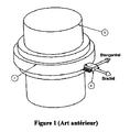
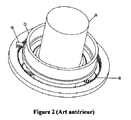
別の観点では、現在の技術において特許文献13が知られている。この特許文献13に
は、略直径方向に磁化された磁石リングまたは磁気ディスクの角度位置を決定するために磁石感知センサを用いる360°回転位置センサが記載されている。この特許文献において、磁石によって生成された磁界の方向を感知するセンサは磁石の外側に配置され、これによって、たとえばステアリングコラムの回転角測定用の軸貫通回転センサが得られる。また特許文献13においては、センサにおける回転を複数回から1回以下に抑えるために、運動の減速に関連付けたセンサが使用されている(図2参照)。この解決法の主な不利点は、分解能および精度を同様に低減するn減速比を用いることに起因している。これは、精度および分解能が非常に高いステアリングコラムの用途には不十分な場合がある。
From another viewpoint,
本発明は、絶対多回転センサを生産するために2つの360°非接触センサを用いることによって、上記の問題を解決するものである。第1非接触センサは0°〜360°の回転部の回転角を測定するのに用いられ、第2センサは回転部の完全な回転の回数を決定するのに用いられる。 The present invention solves the above problem by using two 360 ° non-contact sensors to produce an absolute multi-rotation sensor. The first non-contact sensor is used to measure the rotation angle of the rotating part from 0 ° to 360 °, and the second sensor is used to determine the number of complete rotations of the rotating part.
連続的なn減速比をもつ機械的システムは、2つのセンサ間で統合される。減速機の入力軸は第1センサに連結され、第2センサのロータは減速機の出力軸に連結される。第1センサが完全に1回転をする度に、第2センサは1:nの回転を行う。第2センサは限られた精度および分解能で全絶対角の測定を行えるが、第1センサは第2センサの測定の精緻化を可能にすることによってこの問題を解決するため、360°以上において高い精度および分解能が得られる。第1センサが故障した場合でも、第2センサは回転部の回転における位置を(n倍減速した分解能で)検出でき、第1センサの誤動作を検出することができる。 A mechanical system with a continuous n reduction ratio is integrated between the two sensors. The input shaft of the speed reducer is connected to the first sensor, and the rotor of the second sensor is connected to the output shaft of the speed reducer. Each time the first sensor makes a complete rotation, the second sensor rotates 1: n. The second sensor can measure all absolute angles with limited accuracy and resolution, but the first sensor is high above 360 ° to solve this problem by enabling refinement of the measurement of the second sensor. Accuracy and resolution are obtained. Even when the first sensor fails, the second sensor can detect the position of rotation of the rotating unit (with a resolution reduced by n times), and can detect a malfunction of the first sensor.
以下の解決法は、異なる形状構造(2回転センサ、3回転センサなど、どんな回転数でも精度と分解能が同じもの)、特に軸貫通装置の場合に有利に適合されると共に、測定の信頼性を高めることができる。 The following solutions are advantageously adapted for different geometries (two-turn sensors, three-turn sensors, etc., with the same accuracy and resolution at any number of revolutions), especially in the case of shaft penetration devices, and increase the measurement reliability. Can be increased.
本発明は、好ましい構造によると、特許文献13に記載されている種類の2つのセンサを用いる。
第1センサ(メインセンサとも言う)は、360°を越える軌跡においてハンドル角度を測定し、この軌跡における該角度に比例する信号を伝達する。それ以上の角度については、伝達される信号は、同一のモジュロ(modulo)360°角に対して伝達される信号と同じである。この信号のみでは、初期位置に対する相対的なハンドル位置は分かるが、絶対位置は分からない。実際、第1センサは360°周期の周期信号を伝達する。この周期内の角度は正確に測定されるが、シャフトが何周期にあるかは分からない。
According to a preferred structure, the present invention uses two sensors of the type described in US Pat.
A first sensor (also referred to as a main sensor) measures a handle angle in a trajectory exceeding 360 ° and transmits a signal proportional to the angle in the trajectory. For further angles, the signal transmitted is the same as the signal transmitted for the same modulo 360 ° angle. With this signal alone, the handle position relative to the initial position is known, but the absolute position is not known. In fact, the first sensor transmits a periodic signal having a period of 360 °. The angle within this period is accurately measured, but it is not known how many periods the shaft is.
第2センサは、第1センサが現在何周期にあるかを示す機能を有する一方、一定の冗長性を与える機能を有する。これは、信号の精度が、第1センサ信号との相関性において様々な値の比較を可能とするには十分であるものの、確実に劣るためである。実際、伝達された信号が予期された範囲から外れている場合、システムの誤作動が推測できる。 The second sensor has a function of indicating how many cycles the first sensor is currently in, and has a function of giving a certain redundancy. This is because the accuracy of the signal is sufficient to enable comparison of various values in the correlation with the first sensor signal, but it is definitely inferior. In fact, if the transmitted signal is outside the expected range, system malfunction can be inferred.
第2センサ信号を生成する方法は幾つか考えられる。
特許文献11には、インクリメント式の第2信号を生成する方法(ジェネバ駆動)が記載されている。この信号は第1センサが何回転にあるかを正確に示すが、(インクリメント値を用いて)不連続であるため、ユーザはこの信号を使用して冗長性を得ることはできない。
There are several possible methods for generating the second sensor signal.
本発明では、メインシャフト(図11、参照符号1)と第2センサとの間の連続減速を行う機械的手段を使用し、したがって、第2センサの機械的な角度位置は、メインシャフトを基に測定される角度位置に略比例する。 In the present invention, mechanical means for continuously decelerating between the main shaft (FIG. 11, reference numeral 1) and the second sensor is used. Therefore, the mechanical angular position of the second sensor is based on the main shaft. Is approximately proportional to the angular position measured.
第1センサの信号は入力軸の角度(360°まで)に比例し、360°周期で周期的である。この信号によって、1回転における位置が正確に示される。
第2センサの信号は軌跡全体における入力軸の角度に略比例するが、センサ1の信号よりは精度が劣る。
The signal of the first sensor is proportional to the angle of the input shaft (up to 360 °) and is periodic with a period of 360 °. This signal accurately indicates the position in one rotation.
The signal of the second sensor is substantially proportional to the angle of the input shaft in the entire trajectory, but is less accurate than the signal of the
これによって、軌跡全体における位置が大まかに示される。
有利なことに、両信号を電子的に組み合わせることによって、軌跡全体における入力軸位置に比例する、信号2と同種であるが第1信号の精度を有する信号を合成することができる。このため、精度および分解能において有意な利点がある。
As a result, the position in the entire trajectory is roughly indicated.
Advantageously, by combining the two signals electronically, it is possible to synthesize a signal that is of the same type as
当業者には、一方のシャフトから他方のシャフトへの減速を可能にする幾つかの手段について知られている。寸法の点から最も有利な手段は、次のような、減速比が10の3〜5乗のものである:
ホイールおよびウォームの減速;
ギアトレーンの減速;
ギアホイールの直接的な減速:この解決法は可能であるが、寸法の点からは有利でない;
磁気トルクによる減速。
The person skilled in the art is aware of several means that allow deceleration from one shaft to the other. The most advantageous means in terms of size are those with a reduction ratio of 10 to the fifth power:
Wheel and worm deceleration;
Gear train deceleration;
Direct reduction of the gear wheel: this solution is possible but not advantageous in terms of dimensions;
Deceleration by magnetic torque.
図1に示す両信号は、たとえばマイクロコントローラに対して出力されてもよい。このマイクロコントローラは、第1信号および第2信号から、第2信号よりも精度および分解能が有意に向上した単調増加信号を生成する。 Both signals shown in FIG. 1 may be output to a microcontroller, for example. The microcontroller generates a monotonically increasing signal from the first signal and the second signal with significantly improved accuracy and resolution over the second signal.
本発明は、図1〜図20を参照することによって一層理解されるであろう。図1〜図20は好ましい実施形態を示すが、冗長性が組み込まれた高精度の多回転絶対角センサは、この種のものに限られない。 The present invention will be better understood with reference to FIGS. 1 to 20 show preferred embodiments, the high-precision multi-turn absolute angle sensor with built-in redundancy is not limited to this type.
本発明は、360°以上の複数回転の角度に対応したトルクおよび回転磁気位置センサの分野に関する。より詳細には、本発明は、ステアリングコラムのねじれおよび自動車のステアリングコラムの角度位置を測定するためのトルクおよび位置センサに関するが、この用途に限られない。 The present invention relates to the field of torque and rotary magnetic position sensors corresponding to a plurality of rotation angles of 360 ° or more. More particularly, the present invention relates to a torque and position sensor for measuring steering column twist and the angular position of an automobile steering column, but is not limited to this application.
ドライバがステアリングコラムに与えるトルクは、パワーステアリングのレベルを決定するのに必要な情報である。この情報によって、ドライバはより簡単にハンドルを回すことができる。トルクおよびステアリングコラムの位置に関する情報は、自動車のアシスト性および安定性を最適化するためにまとめられる。本発明は、360°以上の位置に対応するセンサと磁気トルクセンサ(たとえば、特許文献14に記載)とを適切に関連付ける解決法を提案する。この解決法によって、感度を最適化し、部品の大きさおよび重量を最小にすると共に、取り付けが簡単で非常にコンパクトな統合体が提供される。現在の技術において、トルクおよび位置についての解決法は見つけられるが、そうした解決策は単に従来のトルクセンサおよび位置センサを隣接して配置するものである。たとえば特許文献15は、トルクセンサと多回転位置センサとを用いた解決法を提案しているが、これは単に磁気多回転位置センサに隣接して磁気トルクセンサを配置したものであり、大変な過密状態を生じさせるものである。すなわち、複数のホール素子が異なる平面にあり、トルクセンサと位置センサとの間に磁気的な相互作用があるため、複数のPCBまたは1つのフレキシブルPCBを使用しなければならない。
The torque applied by the driver to the steering column is information necessary to determine the power steering level. With this information, the driver can turn the handle more easily. Information about torque and steering column position is compiled to optimize the assist and stability of the vehicle. The present invention proposes a solution for appropriately associating a sensor corresponding to a position of 360 ° or more with a magnetic torque sensor (for example, described in Patent Document 14). This solution provides a very compact integration that optimizes sensitivity, minimizes part size and weight, and is easy to install. In the current technology, a solution for torque and position is found, but such a solution is simply to place a conventional torque sensor and position sensor adjacent to each other. For example,
このため、本発明はこれらの不利点を解決する方法を提案する。トルクと位置センサを再編成するこの新しい内蔵型センサは、4つの異なる磁気構造を含む。この磁気構造とは
:ブリーチに取り付けら放射状に磁化された複数の磁石を含み、トルクセンサに属する、第1のロータ磁気構造と;複数の歯を有する2つの同心リングを含み、トルクセンサに属する、第2のステータ磁気構造と;磁石感知要素が配置される測定間隙を形成すべく、閉鎖アームによって拡張された2つの同心リング部分からなり、トルクセンサに属する、第3の固定コレクタと;ステータ部分のリング間に配置され直径方向に磁化された磁石(またはハルバッハ磁石)を含み、トルクセンサの第2の磁気構造を支持するプラスチック部分の上におけるキャストから成形可能である、第4の構造と、である。MLX90316または他の種類の磁石感知要素は、位置磁石センサの外部に配置され、トルクセンサの磁石感知要素と同じPCBに属する。
For this reason, the present invention proposes a method for solving these disadvantages. This new self-contained sensor that reorganizes torque and position sensors includes four different magnetic structures. This magnetic structure includes: a first rotor magnetic structure that includes a plurality of radially magnetized magnets attached to a breech and belongs to a torque sensor; and includes two concentric rings having a plurality of teeth and belongs to a torque sensor A second stator magnetic structure; a third fixed collector consisting of two concentric ring parts extended by a closing arm to form a measurement gap in which the magnet sensing element is arranged and belonging to a torque sensor; A fourth structure, comprising a diametrically magnetized magnet (or Halbach magnet) disposed between the rings of the parts and moldable from a cast on a plastic part that supports the second magnetic structure of the torque sensor; . MLX90316 or other type of magnet sensing element is located outside the position magnet sensor and belongs to the same PCB as the magnet sensing element of the torque sensor.
この構造によって、軸方向における大きさがトルクセンサのみの場合と同じトルクおよび位置センサが得られる。この構造において、トルクセンサ磁石と位置センサ磁石とは同心である。また、すべてのホール素子はこれらのセンサの回転軸に垂直な磁石正中面に位置する。利点としては、1つのPCB上にすべてのホール素子を挿入でき、また、一方のセンサから他方のセンサに対する磁気相互作用をなくすことができる。 With this structure, the same torque and position sensor as in the case of only the torque sensor in the axial direction can be obtained. In this structure, the torque sensor magnet and the position sensor magnet are concentric. All Hall elements are located on the median plane of the magnet perpendicular to the rotation axis of these sensors. As an advantage, all Hall elements can be inserted on one PCB, and magnetic interaction from one sensor to the other can be eliminated.
このような統合型センサのコストは、構成要素を共有することによって削減される。すなわち、位置センサ磁石およびトルクセンサの同心リングはキャストにより同時に成形でき、1部品として形成可能である。同様に、トルクおよび位置センサのホールセンサはすべて同じ単一のPCBの一部となる。 The cost of such an integrated sensor is reduced by sharing the components. That is, the concentric rings of the position sensor magnet and the torque sensor can be formed simultaneously by casting and can be formed as one part. Similarly, the torque and position sensor hall sensors are all part of the same single PCB.
この構造に対し、特許文献15の最初の部分に記載されるように、減速および絶対位置センサを追加することができる。
有利な方法において、1つのハウジング内に統合するために、両検出システムは互いに近接して配置される。このため装置はコンパクトとなり、監視を行う装置に容易に載置できる。
To this structure, deceleration and absolute position sensors can be added as described in the first part of US Pat.
In an advantageous manner, both detection systems are arranged close to each other for integration in one housing. For this reason, the apparatus becomes compact and can be easily placed on a monitoring apparatus.
本発明は、図21〜図25を参照することによって、一層理解されるであろう。図21〜図25は好ましい実施形態を示すが、冗長性が組み込まれた高精度の多回転絶対角センサは、この種のものに限られない。 The present invention will be better understood with reference to FIGS. 21 to 25 show a preferred embodiment, the high-precision multi-turn absolute angle sensor with built-in redundancy is not limited to this type.
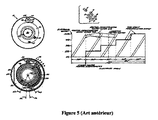
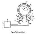
図1〜図9は、本明細書の冒頭部分に記載した従来技術を示す図面である。
図10は本発明の出力信号を示す。第1信号は高精度の分解能の360°(1回転)における周期信号であり、第2信号はこの周期信号の4分の1の分解能の4回転における絶対信号である。
1 to 9 are drawings showing the prior art described at the beginning of this specification.
FIG. 10 shows the output signal of the present invention. The first signal is a periodic signal at 360 ° (one rotation) with a high resolution, and the second signal is an absolute signal at four rotations with a resolution of a quarter of the periodic signal.
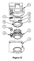
図11〜図15は、ホイールおよびウォームを備える減速機の使用を示す。
大口径のウォーム1は、測定されるシャフト(たとえば、自動車のステアリングコラム
)周囲に搭載されるように、中が空洞になっている。このウォームは測定されるシャフトに取り付けられている。直径方向に磁化された第1磁石3は、このウォームに連結され、1回転を通じて精密信号を感知する第1センサの一部を成す。この磁石は、磁気ブリーチ8に搭載されてもされなくてもよい。本出願において、ウォームはセンサハウジング9に軸留めされ、ハウジングは固定されている。このウォームは、第2磁石7が連結されるスプロケット4を回転させるように駆動する。第2磁気センサの一部は、精度は劣るが軌跡全体にわたる信号を感知する(図10の信号n°2)。このスプロケットは、ハウジング9に軸留めされている。自動車ハンドルの角度軌跡は、多くの場合2〜5回転分であるが、これらの値に限らない。回転ポインタである磁石7が軌跡全体において1回転にわずかに満たない回転をするように、減速比が選択される。この角度軌跡は、分解能の点で、第2センサの可能性から最も利点が得られるものである。図に示す例において、ウォーム1には3つの溝があり、スプロケット4には13個の歯がある。したがって、減速比は4.33であり、これは軌跡が4回転のハンドルに適合する。この運動変換においてわずかな緩みは許容されるが、不可避な程度にすべきであり、減速時の緩みに関係する寄生ヒステリシスを追加することによって第2センサの精度を過度に低下させないようにすべきである。
11-15 illustrate the use of a reducer with a wheel and worm.
The large-
センサ2は、直径方向に磁化された磁石3の動径(radial)成分および接線(tangentiel)成分を測定する。
センサ6は、直径方向に磁化された磁石7の軸方向成分および接線成分を測定する。
The
The
この種の構造を選択することによって、部品数を抑えたコンパクトなセンサが得られる。また、これらの部品はプラスチック注入成形によって低コストで容易に大量生産できる。更に、この構造によって同一のPCB5に2つのセンサ2,6を配置することが可能となり、製造コストの面で大きな利点がある。
By selecting this type of structure, a compact sensor with a reduced number of parts can be obtained. These parts can be easily mass-produced at low cost by plastic injection molding. Furthermore, this structure makes it possible to arrange the two
図16〜図19は、クラスタ減速機の使用を示す。
中空の第1ホイール1はシャフトに連結されており、その角度位置が測定される必要がある。このシャフトは、ホイール1を貫通する。
16-19 illustrate the use of a cluster reducer.
The hollow
直径方向に磁化された第1磁石3は、このホイールに連結され、1回転を通じて精密信号を感知する第1センサの一部を成す(図10、信号n°1)。スプロケットとホイールとを含む第2可動部12は、第1ホイール1と噛み合う。第2可動部と同様に、第3可動部13は第2可動部と噛み合い、第4可動部14を回転させるように駆動する。すべての可動部はハウジング9内部に軸留めされる。クラスタと呼ばれるこのような可動部のアセンブリによって、ホイール1の角速度が減速される。
A diametrically magnetized
第4可動部は、直径方向に磁化された磁石7と、磁気シールドとして機能する軟鉄リング16とを備える。
第2磁石7は粗い第2信号(図10、信号n°2)のセンサの一部であるが、軌跡全体にわたって拡張される。
The fourth movable part includes a
The
第2センサはシャフトに貫通されてもされなくてもよく、第4可動部14とハウジング9との軸は離間してもよい。このセンサによって測定される磁界成分は、シャフトが貫通していない場合、磁石回転軸の1点において互いに直交する2つの動径成分である。あるいはシャフトが貫通している場合は、磁石の外側の1点における動径成分および接線成分である。
The second sensor may or may not be penetrated by the shaft, and the axis of the fourth
上記の例と同様に、減速比は、第4可動部14が、したがって磁石7が、入力軸の全体軌跡において1回転にわずかに満たない回転を行うように選択される。
可動部の数は、大きさの制約または所要の軌跡に適合するように変更してもよい。
Similar to the above example, the reduction ratio is selected such that the fourth
The number of movable parts may be varied to suit size constraints or required trajectories.
送信されるトルクが非常に小さい場合、スプロケット歯の圧力角度を低くすることができる(たとえば、12°)。これによって、第2センサの精度に影響を与える緩みが最小に制限される。実際、回転の復号機能に必要な精度はあまり高くないが、冗長性機能に必要な精度はかなり高い。 If the transmitted torque is very small, the pressure angle of the sprocket teeth can be lowered (eg, 12 °). This limits the slack that affects the accuracy of the second sensor to a minimum. In fact, the accuracy required for the rotation decoding function is not very high, but the accuracy required for the redundancy function is quite high.
すべての可動部と、可動部を保持するハウジング9とは、プラスチック注入成形によって経済的に得られる。センサ2,6は、単一のPCB5に溶接されるので、製法が経済的となる。
All the movable parts and the
図に示す例において、以下のスプロケットが選択される:
入力ホイール1(歯数:60)
ホイール12(歯数:12,34)
ホイール13(歯数:12,39)
出力ホイール14(歯数:35)。
In the example shown in the figure, the following sprockets are selected:
Input wheel 1 (number of teeth: 60)
Wheel 12 (Number of teeth: 12, 34)
Wheel 13 (Number of teeth: 12, 39)
Output wheel 14 (number of teeth: 35).
これによって減速比は5.37となる。したがって、本明細書においては、軌跡が5回転のハンドルを例として示している。
図20は、直接的な磁気接続の使用を示す。
As a result, the reduction ratio becomes 5.37. Therefore, in the present specification, a handle having a trajectory of 5 turns is shown as an example.
FIG. 20 illustrates the use of a direct magnetic connection.
図に示す例において、直径方向に磁化された磁石リング3はシャフトに連結されており、このシャフトの回転は測定する必要がある。多極磁石リング20は同一平面上に配置され、接触作用するハウジングに軸留めされる。実際、N極とS極はメイン磁石3のS極とN極に交互に向い合い、2つの磁石間で角速度が減速される。非磁性の薄壁によって、あるいはホイール間での機械的な直接接触なく、減速を可能にする非接触磁気減速システムについては、当業者によく知られている。
In the example shown in the figure, the
図に示す例において、第1シャフト磁石3には1組の極があり、第2シャフト磁石20には6組の極がある。これによって、2つのシャフト間の減速比が6となり、軌跡が約6回転のハンドルを測定できるようにシステムは適合される。
In the example shown in the figure, the
第2ホイールの中心に配置された2極磁石7は、上記の例と同様に、第2ホイールの角度位置を取得できる。メイン磁石3はステアリングコラムへ堅固に連結されるため、その位置が正確に測定できる。
The
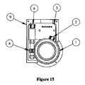
図21および図22は、トルクセンサと360°絶対位置センサとのコンパクトなアセンブリの正面図および断面図である。このアセンブリは:
2ステータ多極磁石10と、2つのコレクタ8と、PCB5に搭載された2つの磁石感知要素7とを備えるトルクセンサ;と、
アセンブリの大きさを最適にするために2つのステータ間に適切に配置され、直径方向に磁化された磁石3と、PCB5上に配置され、磁石3の軸方向成分および接線成分を測定するセンサ6とを含む位置センサ;と
に再編成される。磁石3はステータと同時にキャスト成形することができ、トルクおよび位置の測定は、磁石感知要素を用いて同一面で行える。
21 and 22 are a front view and a cross-sectional view of a compact assembly of a torque sensor and a 360 ° absolute position sensor. This assembly is:
A torque sensor comprising two
A
図23は、トルクセンサの2ASICホール7、360°位置センサのASICホール、ASICが組み込まれた単一のPCB、およびトルクセンサコレクタ構造を示す。
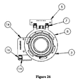
図24、図25、および図26は、トルクセンサと多回転絶対位置センサとのアセンブリの斜視図、断面図、および正面図である。このアセンブリは以下のように再編成される
。
FIG. 23 shows the 2
24, 25, and 26 are a perspective view, a cross-sectional view, and a front view of the assembly of the torque sensor and the multi-rotation absolute position sensor. This assembly is reorganized as follows.
2ステータ多極磁石10と、2つのコレクタ8と、1つのPCB5に組み付けられた2つの磁石感知要素7とを含むトルクセンサ、
周期θ/nの「周期」関数に従って信号を生成して周期的な角度位置を提供する検出システムであって、アセンブリの大きさを最適にするために2つのステータ間に適切に配置される直径方向に磁化された磁石3と、PCB5上に配置され、磁石3の軸方向成分および接線成分を測定するセンサ6とを含む検出システム、
軌跡θにおける絶対信号を生成する検出システムであって、直径方向に磁化された磁石19と磁石19の軸方向成分および接線成分を測定するセンサ16とを含む、ホイール18およびウォーム11の減速機(図11〜図15を参照)を含む検出システム。
図11〜図19に顕著に見られるように、1つのハウジングに組み付けられたコンパクトなセンサを実現するために、両検出システム(すなわち、センサ2,6)は互いに接近して有意に配置される。
A torque sensor comprising two
A detection system that generates a signal according to a “period” function of period θ / n to provide a periodic angular position, the diameter appropriately positioned between the two stators to optimize the size of the assembly A detection system comprising a
A detection system for generating an absolute signal in the locus θ, including a diametrically
As can be seen prominently in FIGS. 11-19, both detection systems (ie,
Claims (17)
前記検出システムのうちの少なくとも第1の検出システムは、前記シャフトに連結される入力軸の運動を連続的に変換し、周期θ/nの「周期」関数に従って信号を生成して前記シャフトの周期的な角度位置を提供するための機械的システムを含み、前記第1の検出システムは、直径方向に磁化されている第1の磁石を備え、前記第1の磁石は前記シャフトの周囲に取り付けられる中空のウォームに連結されており、
前記検出システムのうちの少なくとも第2の検出システムは、前記シャフトの軌跡θにおける絶対信号を生成するためのシステムを含み、前記第2の検出システムは、スプロケットに連結される第2の磁石を備え、前記ウォームは前記スプロケットを回転させるように駆動し、
前記第1の検出システムは、位相が略90度ずれた2つの正弦波信号を供給するために、磁石によって生成される磁界の動径成分と、接線成分とを測定する、略同位置に配置された少なくとも2つの磁石感知要素を含み、
θおよびnは、θ/n=360(n>1)の関係を満たし、
前記第2の検出システムは、位相が略90度ずれた2つの正弦波信号を供給するために、磁界の接線成分、動径成分、または軸方向成分と、磁界の動径成分、軸方向成分、または接線成分とを測定する、略同位置に配置された少なくとも2つの磁石感知要素を含み、
前記第1、第2の検出システムの2つのセンサは共に、1つの印刷回路基板上に配置される、絶対位置磁気センサ。 An absolute position magnetic sensor for measuring an angular position in a locus θ of the shaft, the shaft passing through the sensor, the sensor comprising at least two detection systems for detecting the position of the shaft ,
At least a first detection system of the detection systems continuously converts motion of an input shaft coupled to the shaft and generates a signal according to a “period” function of period θ / n to generate a period of the shaft. Including a mechanical system for providing an angular position, wherein the first detection system comprises a first magnet that is diametrically magnetized, the first magnet being mounted around the shaft. Connected to a hollow worm,
At least a second detection system of the detection system includes a system for generating an absolute signal in the shaft trajectory θ, and the second detection system comprises a second magnet coupled to a sprocket. The worm is driven to rotate the sprocket;
The first detection system is arranged at substantially the same position for measuring the radial component and the tangential component of the magnetic field generated by the magnet in order to supply two sinusoidal signals that are approximately 90 degrees out of phase. Including at least two magnet sensing elements formed,
θ and n satisfy the relationship θ / n = 360 (n> 1),
The second detection system supplies two sinusoidal signals that are approximately 90 degrees out of phase, so that the tangential component, radial component, or axial component of the magnetic field, and the radial component, axial component of the magnetic field. or measuring the tangential component, seen contains at least two magnets sensing element is substantially arranged in the same position,
An absolute position magnetic sensor in which the two sensors of the first and second detection systems are both arranged on one printed circuit board .
トーションバーにかかるねじれトルクを推定するために、トーションバーによって同軸に接続された入力軸および出力軸の相対的角度位置±Ψ(Ψ>20)を検出するための少なくとも1つの検出システムと、同検出システムは、放射状に配向された複数の磁石を含む第1のロータ磁気構造と、近傍に少なくとも1つの磁石感知要素が配置された歯によって拡張される2つのリングを含む第2のステータ構造とからなることと;
請求項1乃至10のいずれか一項に記載の絶対位置磁気センサにおける第2の検出システムと;
少なくとも1つの信号処理システムと、を含み、
θ、Ψ、およびnは、θ/n=360(θ/Ψ>20、n≧1)の関係を満たし;
前記シャフトは、トルクセンサの入力軸または出力軸でもある、アセンブリ。 A position sensor assembly for detecting twisting of a steering column,
At least one detection system for detecting the relative angular position ± Ψ (Ψ> 20) of the input shaft and the output shaft connected coaxially by the torsion bar to estimate the torsional torque applied to the torsion bar; The detection system includes a first rotor magnetic structure that includes a plurality of radially oriented magnets, and a second stator structure that includes two rings extended by teeth with at least one magnet sensing element disposed in the vicinity thereof. Consisting of:
A second detection system in the absolute position magnetic sensor according to any one of claims 1 to 10;
At least one signal processing system;
θ, ψ, and n satisfy the relationship θ / n = 360 (θ / ψ> 20, n ≧ 1);
The assembly, wherein the shaft is also an input shaft or an output shaft of a torque sensor.
Applications Claiming Priority (3)
| Application Number | Priority Date | Filing Date | Title |
|---|---|---|---|
| FR0705373 | 2007-07-24 | ||
| FR0705373A FR2919385B1 (en) | 2007-07-24 | 2007-07-24 | NON-CONTACT MAGNETIC SENSOR WITH ABSOLUTE MULTITOUR POSITION WITH THROUGH SHAFT |
| PCT/FR2008/001093 WO2009047401A2 (en) | 2007-07-24 | 2008-07-23 | Non-contact multi-turn absolute position magnetic sensor comprising a through-shaft |
Related Child Applications (1)
| Application Number | Title | Priority Date | Filing Date |
|---|---|---|---|
| JP2014238646A Division JP2015038514A (en) | 2007-07-24 | 2014-11-26 | Shaft penetration noncontact multiple rotation absolute position magnetic sensor |
Publications (2)
| Publication Number | Publication Date |
|---|---|
| JP2010534330A JP2010534330A (en) | 2010-11-04 |
| JP5680962B2 true JP5680962B2 (en) | 2015-03-04 |
Family
ID=39353497
Family Applications (2)
| Application Number | Title | Priority Date | Filing Date |
|---|---|---|---|
| JP2010517448A Expired - Fee Related JP5680962B2 (en) | 2007-07-24 | 2008-07-23 | Non-contact multi-turn absolute position magnetic sensor |
| JP2014238646A Pending JP2015038514A (en) | 2007-07-24 | 2014-11-26 | Shaft penetration noncontact multiple rotation absolute position magnetic sensor |
Family Applications After (1)
| Application Number | Title | Priority Date | Filing Date |
|---|---|---|---|
| JP2014238646A Pending JP2015038514A (en) | 2007-07-24 | 2014-11-26 | Shaft penetration noncontact multiple rotation absolute position magnetic sensor |
Country Status (8)
| Country | Link |
|---|---|
| US (1) | US9097559B2 (en) |
| EP (1) | EP2171403B1 (en) |
| JP (2) | JP5680962B2 (en) |
| KR (1) | KR101497740B1 (en) |
| CN (1) | CN101802557B (en) |
| ES (1) | ES2627225T3 (en) |
| FR (1) | FR2919385B1 (en) |
| WO (1) | WO2009047401A2 (en) |
Families Citing this family (52)
| Publication number | Priority date | Publication date | Assignee | Title |
|---|---|---|---|---|
| FR2936307B1 (en) | 2008-09-24 | 2010-09-17 | Moving Magnet Tech Mmt | LINEAR OR PERMANENT MAGNET ROTATING POSITION SENSOR FOR DETECTION OF A FERROMAGNETIC TARGET |
| FR2937722B1 (en) | 2008-10-24 | 2010-11-26 | Moving Magnet Tech Mmt | MAGNETIC POSITION SENSOR WITH FIELD DIRECTION MEASUREMENT AND FLOW COLLECTOR |
| US20100235054A1 (en) * | 2009-03-11 | 2010-09-16 | Kostal Of America | Steering angle sensor |
| FR2947902B1 (en) | 2009-07-07 | 2011-07-22 | Moving Magnet Technologies M M T | ABSOLUTE AND MULTI-PERIODIC POSITION SENSOR |
| JP5789911B2 (en) * | 2009-10-06 | 2015-10-07 | 株式会社ジェイテクト | Rotation angle detection device and electric power steering device |
| JP5540308B2 (en) * | 2009-10-16 | 2014-07-02 | 株式会社ミツトヨ | Rotary encoder |
| CN102648388B (en) * | 2009-10-19 | 2015-04-15 | 贝邓肯电子公司 | Multi-turn sensor |
| FR2952430B1 (en) | 2009-11-06 | 2012-04-27 | Moving Magnet Technologies M M T | BIDIRECTIONAL MAGNETIC POSITION SENSOR WITH FIELD ROTATION |
| US8901921B2 (en) * | 2009-11-25 | 2014-12-02 | Infineon Technologies Ag | Angle measurement system for determining an angular position of a rotating shaft |
| JP5067676B2 (en) * | 2010-03-12 | 2012-11-07 | 株式会社デンソー | Sensor unit and magnetism collecting module |
| FR2964190B1 (en) * | 2010-08-24 | 2013-02-08 | Moving Magnet Tech | MAGNETIC DETECTION DEVICE WITH ABSOLUTE MULTITOUR POSITION |
| MY165856A (en) | 2010-08-24 | 2018-05-18 | Rotork Controls | Apparatus adapted to provide an indication of an angular position of an input member over multiple turns |
| AT510377B1 (en) | 2010-09-14 | 2014-06-15 | Zentr Mikroelekt Dresden Gmbh | METHOD AND EMBODIMENTS FOR THE ABSOLUTE POSITION DETERMINATION BY MEANS OF TWO HALL SENSORS |
| FR2965347B1 (en) | 2010-09-29 | 2015-04-03 | Moving Magnet Tech | IMPROVED POSITION SENSOR |
| DE102011002563A1 (en) * | 2010-12-20 | 2012-06-21 | Robert Bosch Gmbh | sensor arrangement |
| DE102011078597A1 (en) * | 2011-07-04 | 2013-01-10 | Continental Teves Ag & Co. Ohg | Method and device for measuring the absolute angle of rotation |
| US9593967B2 (en) | 2011-07-17 | 2017-03-14 | Bourns, Inc. | High-resolution non-contacting multi-turn sensing systems and methods |
| CN103090774A (en) * | 2011-10-28 | 2013-05-08 | 北京精密机电控制设备研究所 | Sensor integrating magnetic pole location and output displacement |
| KR101863780B1 (en) * | 2011-11-29 | 2018-06-01 | 엘지이노텍 주식회사 | Torque Index Sensor |
| DE102012203158A1 (en) | 2012-02-29 | 2013-08-29 | Zentrum Mikroelektronik Dresden Ag | Device for sensor system for contactless detection of absolute position of rotatable element, has magneto-sensitive sensors that detect axial component of magnetic field, where absolute position is recognized over certain angular range |
| DE102012024382A1 (en) * | 2012-12-13 | 2014-06-18 | Valeo Schalter Und Sensoren Gmbh | Device having a torque sensor device and optionally a steering angle sensor device for a motor vehicle, motor vehicle and method for producing a torque sensor device |
| DE102012024383A1 (en) | 2012-12-13 | 2014-06-18 | Valeo Schalter Und Sensoren Gmbh | Device having a torque sensor device and a steering angle sensor device for a motor vehicle, motor vehicle and method for producing a device |
| EP2936097A1 (en) * | 2012-12-21 | 2015-10-28 | Continental Teves AG & Co. oHG | Method for detecting a torque applied to a shaft |
| DE102012025280A1 (en) * | 2012-12-21 | 2014-06-26 | Valeo Schalter Und Sensoren Gmbh | A sensor device having a torque sensor device and a steering angle sensor device for a steering shaft, which has a steering wheel-side input shaft part and an output shaft part, steering shaft device for a motor vehicle, motor vehicle and method for producing a steering shaft device |
| US10856452B1 (en) * | 2013-03-14 | 2020-12-01 | David Fiori, Jr. | Sensor apparatus |
| DE102013006379A1 (en) * | 2013-04-13 | 2014-10-16 | Valeo Schalter Und Sensoren Gmbh | Sensor device with a torque sensor device and an incremental sensor device and motor vehicle |
| DE102013224098A1 (en) * | 2013-11-26 | 2015-05-28 | Robert Bosch Gmbh | Sensor arrangement for detecting angles of rotation on a rotating component in a vehicle |
| WO2015147740A1 (en) * | 2014-03-28 | 2015-10-01 | Allied Motion Stockholm Ab | Method for deriving an absolute multiturn rotational angle of a rotating shaft, and a device therefore |
| KR20160078616A (en) | 2014-12-24 | 2016-07-05 | 전자부품연구원 | Apparatus and method for estimating absolute position of driving shaft |
| CN104915711B (en) * | 2015-07-10 | 2017-11-14 | 江苏理工学院 | Absolute angle counter |
| FR3039337B1 (en) | 2015-07-23 | 2017-09-01 | Mmt Sa | COMPACT MOTOREDUCER |
| KR101888480B1 (en) * | 2016-08-11 | 2018-09-20 | 이광남 | Complex Type Torque Sensor |
| DE102016216326A1 (en) * | 2016-08-30 | 2018-03-01 | Schaeffler Technologies AG & Co. KG | Sensor arrangement for determining a number of revolutions of a permanent magnet |
| FR3056841B1 (en) | 2016-09-28 | 2018-08-31 | Moving Magnet Technologies | MOTOREDUCER HAVING A POSITION SENSOR SURROUNDING THE OUTPUT WHEEL |
| CN210570729U (en) * | 2017-03-07 | 2020-05-19 | 松下知识产权经营株式会社 | Rotation angle detecting device |
| JP6791065B2 (en) * | 2017-04-28 | 2020-11-25 | 株式会社Soken | Torque detector and sensor module |
| JP6829663B2 (en) * | 2017-07-04 | 2021-02-10 | ミネベアミツミ株式会社 | Absolute encoder |
| CN107655399A (en) * | 2017-07-12 | 2018-02-02 | 北京军立方机器人科技有限公司 | A kind of multi-turn absolute value encoder and method for detecting position |
| JP6946917B2 (en) | 2017-10-13 | 2021-10-13 | 株式会社ジェイテクト | Sensor device |
| JP2021038925A (en) * | 2017-12-25 | 2021-03-11 | パナソニックIpマネジメント株式会社 | Rotation angle detection device |
| US10816363B2 (en) | 2018-02-27 | 2020-10-27 | Nxp B.V. | Angular sensor system and method of stray field cancellation |
| US10670425B2 (en) | 2018-03-30 | 2020-06-02 | Nxp B.V. | System for measuring angular position and method of stray field cancellation |
| KR101968509B1 (en) * | 2018-05-28 | 2019-04-12 | 엘지이노텍 주식회사 | Torque Index Sensor |
| FR3093181B1 (en) * | 2019-02-25 | 2021-05-07 | Moving Magnet Tech | Position sensor, in particular intended for detecting the torsion of a steering column. |
| US11946773B2 (en) | 2019-03-28 | 2024-04-02 | Denso Corporation | Motor rotation and position detection device and control unit |
| JP7327192B2 (en) | 2019-03-28 | 2023-08-16 | 株式会社デンソー | Detector and controller |
| US11548547B2 (en) * | 2019-05-16 | 2023-01-10 | Steering Solutions Ip Holding Corporation | Highly integrated EPS system |
| US11486742B2 (en) | 2019-08-16 | 2022-11-01 | Nxp B.V. | System with magnetic field shield structure |
| US11307055B2 (en) | 2019-09-18 | 2022-04-19 | Analog Devices International Unlimited Company | Sensor with magnetic shield |
| NL2024705B1 (en) * | 2020-01-20 | 2021-09-08 | Ridder Drive Systems B V | SHIFT DEVICE, ELECTRICAL DRIVE AND PROCEDURE FOR SETTING A SHIFT DEVICE |
| EP4016008A1 (en) | 2020-12-17 | 2022-06-22 | Renesas Electronics America Inc. | Position sensor with improved magnetic stray field immunity |
| FR3118804B1 (en) | 2021-01-14 | 2023-02-10 | Richard Arlot | Non-contact position sensor comprising a permanent magnet. |
Family Cites Families (23)
| Publication number | Priority date | Publication date | Assignee | Title |
|---|---|---|---|---|
| US3624642A (en) * | 1969-09-03 | 1971-11-30 | Inductosyn Corp | Digital and analog converter |
| FR2670889B1 (en) * | 1990-11-30 | 1995-05-24 | Skf France | ENGLISH RACKED WOODEN STAIRCASES, POSTS, RAILS, SIMPLIFIED MANUFACTURING AND LAYING GUARDS. |
| JP2571803Y2 (en) * | 1991-05-30 | 1998-05-20 | ナイルス部品株式会社 | Operating position detection mechanism of motor actuator |
| JP2738199B2 (en) * | 1992-03-02 | 1998-04-08 | 三菱電機株式会社 | Rotation or movement detection method and device |
| WO2001020290A1 (en) * | 1999-09-16 | 2001-03-22 | Delphi Technologies, Inc. | Symmetry compensation for encoder pulse width variation |
| JP2002116057A (en) * | 2000-10-06 | 2002-04-19 | Yaskawa Electric Corp | Multi-rotational absolute value encoder |
| KR100913631B1 (en) * | 2001-10-19 | 2009-08-24 | 가부시키가이샤 야스카와덴키 | Multirotation type encoder |
| JP3920113B2 (en) * | 2002-03-05 | 2007-05-30 | アルプス電気株式会社 | Rotation angle detector |
| JP4036806B2 (en) * | 2003-08-27 | 2008-01-23 | 株式会社ジェイテクト | Torque detection device |
| JP4474872B2 (en) * | 2003-09-02 | 2010-06-09 | パナソニック株式会社 | Absolute rotation angle and torque detector |
| JP2005140557A (en) * | 2003-11-04 | 2005-06-02 | Asahi Kasei Electronics Co Ltd | Steering angle detector |
| US7174795B2 (en) * | 2004-02-06 | 2007-02-13 | Delphi Technologies, Inc. | Integrated non-contacting torque and absolute position sensor for steering applications |
| FR2872896B1 (en) * | 2004-07-09 | 2008-01-11 | Moving Magnet Tech | POSITION SENSOR, PARTICULARLY FOR MEASURING THE TORSION OF A STEERING COLUMN |
| JP2006105827A (en) * | 2004-10-06 | 2006-04-20 | Tokai Rika Co Ltd | Rotation angle sensor |
| DE102004053690A1 (en) * | 2004-11-06 | 2006-05-11 | Zf Lenksysteme Gmbh | Method and device for determining a steering angle of a vehicle |
| JP2006234723A (en) * | 2005-02-28 | 2006-09-07 | Matsushita Electric Ind Co Ltd | Method of correcting rotation angle in rotation angle detector |
| EP1830155A1 (en) | 2005-02-10 | 2007-09-05 | Matsushita Electric Industrial Co., Ltd. | Rotation angle detection device and rotation angle correction method |
| JP2006220529A (en) * | 2005-02-10 | 2006-08-24 | Matsushita Electric Ind Co Ltd | Detection device for absolute angle of rotation and torque |
| JP2006300704A (en) * | 2005-04-20 | 2006-11-02 | Hitachi Cable Ltd | Rotation angle detecting sensor |
| JP2007051953A (en) * | 2005-08-18 | 2007-03-01 | Asahi Kasei Electronics Co Ltd | Magnetic encoder |
| JP5128766B2 (en) * | 2005-11-08 | 2013-01-23 | 東洋電装株式会社 | Rudder angle sensor |
| FR2893410B1 (en) * | 2005-11-15 | 2008-12-05 | Moving Magnet Tech Mmt | MAGNETIC ANGULAR POSITION SENSOR FOR RACE UP TO 360 |
| FR2896035B1 (en) * | 2006-01-06 | 2009-01-16 | Moving Magnet Tech | LOW STROKE MAGNETIC POSITION SENSOR, IN PARTICULAR FOR THE TORSION MEASUREMENT OF A STEERING COLUMN |
-
2007
- 2007-07-24 FR FR0705373A patent/FR2919385B1/en active Active
-
2008
- 2008-07-23 JP JP2010517448A patent/JP5680962B2/en not_active Expired - Fee Related
- 2008-07-23 KR KR1020107003977A patent/KR101497740B1/en not_active IP Right Cessation
- 2008-07-23 CN CN200880108213.9A patent/CN101802557B/en not_active Expired - Fee Related
- 2008-07-23 US US12/670,316 patent/US9097559B2/en active Active
- 2008-07-23 EP EP08838034.0A patent/EP2171403B1/en active Active
- 2008-07-23 ES ES08838034.0T patent/ES2627225T3/en active Active
- 2008-07-23 WO PCT/FR2008/001093 patent/WO2009047401A2/en active Application Filing
-
2014
- 2014-11-26 JP JP2014238646A patent/JP2015038514A/en active Pending
Also Published As
| Publication number | Publication date |
|---|---|
| US9097559B2 (en) | 2015-08-04 |
| JP2010534330A (en) | 2010-11-04 |
| FR2919385A1 (en) | 2009-01-30 |
| EP2171403A2 (en) | 2010-04-07 |
| US20100194385A1 (en) | 2010-08-05 |
| EP2171403B1 (en) | 2017-03-22 |
| CN101802557A (en) | 2010-08-11 |
| ES2627225T3 (en) | 2017-07-27 |
| WO2009047401A3 (en) | 2009-08-20 |
| WO2009047401A2 (en) | 2009-04-16 |
| FR2919385B1 (en) | 2009-10-09 |
| JP2015038514A (en) | 2015-02-26 |
| CN101802557B (en) | 2014-01-29 |
| KR101497740B1 (en) | 2015-03-02 |
| KR20100052484A (en) | 2010-05-19 |
Similar Documents
| Publication | Publication Date | Title |
|---|---|---|
| JP5680962B2 (en) | Non-contact multi-turn absolute position magnetic sensor | |
| JP5480967B2 (en) | Multi-period absolute position detector | |
| JP5580427B2 (en) | Steering torque and steering angle measuring device and vehicle steering device provided with the same | |
| US6901816B2 (en) | Apparatus and method for detecting absolute position using difference between detection signals of two detectors | |
| US20060145688A1 (en) | Transducer of angular quantities for a cycle | |
| US9114833B2 (en) | Sensor assembly for motor vehicle steering systems | |
| US20100301845A1 (en) | Absolute measurement steering angle sensor arrangement | |
| US20120119731A1 (en) | Angle sensor | |
| JP5071407B2 (en) | Torque sensor and electric power steering apparatus using the same | |
| KR20140069005A (en) | Combined steering torque-steering angle sensor | |
| KR20090002876A (en) | Torque sensor and electronic power steering apparatus having same | |
| JP5001309B2 (en) | Detection device and power steering device | |
| US20090319120A1 (en) | Vehicle steering angle sensor | |
| JP2008241564A (en) | Steering angle detecting device and steering apparatus | |
| KR101339503B1 (en) | Apparatus for detecting torque and angle | |
| KR20150018282A (en) | Torque and angle sensor | |
| JP5331505B2 (en) | Rotation angle detection device and steering device | |
| KR101859768B1 (en) | Torque Index Sub Angle Sensor | |
| JP5016625B2 (en) | Detection device and power steering device | |
| JP2011099727A (en) | Rotational angle detector and rotational angle/torque detector using the same | |
| JP2006234724A (en) | Angle of rotation and torque sensor | |
| KR20130128549A (en) | Angle sensor | |
| JP2011145225A (en) | Failure diagnosis device, rotational angle detector, and failure diagnosis method | |
| JP2008232804A (en) | Torque sensor and electric power steeering device | |
| JP2004191138A (en) | Steering angle detection device |
Legal Events
| Date | Code | Title | Description |
|---|---|---|---|
| A621 | Written request for application examination |
Free format text: JAPANESE INTERMEDIATE CODE: A621 Effective date: 20110722 |
|
| RD04 | Notification of resignation of power of attorney |
Free format text: JAPANESE INTERMEDIATE CODE: A7424 Effective date: 20120206 |
|
| A977 | Report on retrieval |
Free format text: JAPANESE INTERMEDIATE CODE: A971007 Effective date: 20120911 |
|
| A131 | Notification of reasons for refusal |
Free format text: JAPANESE INTERMEDIATE CODE: A131 Effective date: 20121002 |
|
| A521 | Written amendment |
Free format text: JAPANESE INTERMEDIATE CODE: A523 Effective date: 20130104 |
|
| A02 | Decision of refusal |
Free format text: JAPANESE INTERMEDIATE CODE: A02 Effective date: 20130205 |
|
| A521 | Written amendment |
Free format text: JAPANESE INTERMEDIATE CODE: A523 Effective date: 20130605 |
|
| A911 | Transfer of reconsideration by examiner before appeal (zenchi) |
Free format text: JAPANESE INTERMEDIATE CODE: A911 Effective date: 20130717 |
|
| A912 | Removal of reconsideration by examiner before appeal (zenchi) |
Free format text: JAPANESE INTERMEDIATE CODE: A912 Effective date: 20130927 |
|
| A601 | Written request for extension of time |
Free format text: JAPANESE INTERMEDIATE CODE: A601 Effective date: 20140411 |
|
| A602 | Written permission of extension of time |
Free format text: JAPANESE INTERMEDIATE CODE: A602 Effective date: 20140416 |
|
| A521 | Written amendment |
Free format text: JAPANESE INTERMEDIATE CODE: A523 Effective date: 20141126 |
|
| A61 | First payment of annual fees (during grant procedure) |
Free format text: JAPANESE INTERMEDIATE CODE: A61 Effective date: 20150108 |
|
| R150 | Certificate of patent or registration of utility model |
Ref document number: 5680962 Country of ref document: JP Free format text: JAPANESE INTERMEDIATE CODE: R150 |
|
| LAPS | Cancellation because of no payment of annual fees |