JP5519152B2 - Device for acquiring information about anatomical samples using optical microscopy - Google Patents
Device for acquiring information about anatomical samples using optical microscopy Download PDFInfo
- Publication number
- JP5519152B2 JP5519152B2 JP2008554495A JP2008554495A JP5519152B2 JP 5519152 B2 JP5519152 B2 JP 5519152B2 JP 2008554495 A JP2008554495 A JP 2008554495A JP 2008554495 A JP2008554495 A JP 2008554495A JP 5519152 B2 JP5519152 B2 JP 5519152B2
- Authority
- JP
- Japan
- Prior art keywords
- electromagnetic radiation
- frequency
- intensity
- sample
- difference
- Prior art date
- Legal status (The legal status is an assumption and is not a legal conclusion. Google has not performed a legal analysis and makes no representation as to the accuracy of the status listed.)
- Active
Links
- 238000000399 optical microscopy Methods 0.000 title description 2
- 230000005670 electromagnetic radiation Effects 0.000 claims description 66
- 239000000523 sample Substances 0.000 claims description 34
- 238000001228 spectrum Methods 0.000 claims description 14
- 239000012472 biological sample Substances 0.000 claims description 13
- 230000003595 spectral effect Effects 0.000 claims description 11
- 238000005259 measurement Methods 0.000 claims description 3
- 210000000056 organ Anatomy 0.000 claims 1
- 238000000034 method Methods 0.000 description 38
- 230000005535 acoustic phonon Effects 0.000 description 15
- 238000010586 diagram Methods 0.000 description 11
- 230000008569 process Effects 0.000 description 8
- 230000000694 effects Effects 0.000 description 7
- 206010028980 Neoplasm Diseases 0.000 description 6
- 230000003287 optical effect Effects 0.000 description 6
- 239000000835 fiber Substances 0.000 description 5
- 238000000386 microscopy Methods 0.000 description 5
- 238000004611 spectroscopical analysis Methods 0.000 description 4
- 238000001069 Raman spectroscopy Methods 0.000 description 3
- 230000035559 beat frequency Effects 0.000 description 3
- 238000003384 imaging method Methods 0.000 description 3
- 238000005305 interferometry Methods 0.000 description 3
- 230000001902 propagating effect Effects 0.000 description 3
- 239000007787 solid Substances 0.000 description 3
- 201000011510 cancer Diseases 0.000 description 2
- 230000001427 coherent effect Effects 0.000 description 2
- 238000001514 detection method Methods 0.000 description 2
- 238000003745 diagnosis Methods 0.000 description 2
- 230000009977 dual effect Effects 0.000 description 2
- 238000005516 engineering process Methods 0.000 description 2
- 230000005284 excitation Effects 0.000 description 2
- 230000007274 generation of a signal involved in cell-cell signaling Effects 0.000 description 2
- 238000001727 in vivo Methods 0.000 description 2
- 230000003993 interaction Effects 0.000 description 2
- 238000004519 manufacturing process Methods 0.000 description 2
- 238000012986 modification Methods 0.000 description 2
- 230000004048 modification Effects 0.000 description 2
- 238000012544 monitoring process Methods 0.000 description 2
- 239000013307 optical fiber Substances 0.000 description 2
- 201000001320 Atherosclerosis Diseases 0.000 description 1
- 208000007479 Orofaciodigital syndrome type 1 Diseases 0.000 description 1
- 238000001530 Raman microscopy Methods 0.000 description 1
- 238000002679 ablation Methods 0.000 description 1
- 230000001154 acute effect Effects 0.000 description 1
- 210000003484 anatomy Anatomy 0.000 description 1
- 230000005540 biological transmission Effects 0.000 description 1
- BJQHLKABXJIVAM-UHFFFAOYSA-N bis(2-ethylhexyl) phthalate Chemical compound CCCCC(CC)COC(=O)C1=CC=CC=C1C(=O)OCC(CC)CCCC BJQHLKABXJIVAM-UHFFFAOYSA-N 0.000 description 1
- 230000001413 cellular effect Effects 0.000 description 1
- 238000012512 characterization method Methods 0.000 description 1
- 238000006243 chemical reaction Methods 0.000 description 1
- 208000029078 coronary artery disease Diseases 0.000 description 1
- 230000007547 defect Effects 0.000 description 1
- 230000007812 deficiency Effects 0.000 description 1
- 239000003814 drug Substances 0.000 description 1
- 238000001839 endoscopy Methods 0.000 description 1
- 238000007689 inspection Methods 0.000 description 1
- 239000000463 material Substances 0.000 description 1
- 238000000691 measurement method Methods 0.000 description 1
- 238000011089 mechanical engineering Methods 0.000 description 1
- 230000007246 mechanism Effects 0.000 description 1
- 238000002168 optical frequency-domain reflectometry Methods 0.000 description 1
- 201000003455 orofaciodigital syndrome I Diseases 0.000 description 1
- 230000001575 pathological effect Effects 0.000 description 1
- 230000010363 phase shift Effects 0.000 description 1
- 230000010287 polarization Effects 0.000 description 1
- 238000012545 processing Methods 0.000 description 1
- 239000011253 protective coating Substances 0.000 description 1
- 238000005086 pumping Methods 0.000 description 1
- 238000011084 recovery Methods 0.000 description 1
- 239000004065 semiconductor Substances 0.000 description 1
- 239000013589 supplement Substances 0.000 description 1
- 230000002123 temporal effect Effects 0.000 description 1
Images


Classifications
-
- C—CHEMISTRY; METALLURGY
- C07—ORGANIC CHEMISTRY
- C07K—PEPTIDES
- C07K14/00—Peptides having more than 20 amino acids; Gastrins; Somatostatins; Melanotropins; Derivatives thereof
- C07K14/435—Peptides having more than 20 amino acids; Gastrins; Somatostatins; Melanotropins; Derivatives thereof from animals; from humans
- C07K14/705—Receptors; Cell surface antigens; Cell surface determinants
- C07K14/70503—Immunoglobulin superfamily
-
- A—HUMAN NECESSITIES
- A61—MEDICAL OR VETERINARY SCIENCE; HYGIENE
- A61B—DIAGNOSIS; SURGERY; IDENTIFICATION
- A61B3/00—Apparatus for testing the eyes; Instruments for examining the eyes
- A61B3/10—Objective types, i.e. instruments for examining the eyes independent of the patients' perceptions or reactions
- A61B3/102—Objective types, i.e. instruments for examining the eyes independent of the patients' perceptions or reactions for optical coherence tomography [OCT]
-
- A—HUMAN NECESSITIES
- A61—MEDICAL OR VETERINARY SCIENCE; HYGIENE
- A61B—DIAGNOSIS; SURGERY; IDENTIFICATION
- A61B3/00—Apparatus for testing the eyes; Instruments for examining the eyes
- A61B3/10—Objective types, i.e. instruments for examining the eyes independent of the patients' perceptions or reactions
- A61B3/117—Objective types, i.e. instruments for examining the eyes independent of the patients' perceptions or reactions for examining the anterior chamber or the anterior chamber angle, e.g. gonioscopes
-
- A—HUMAN NECESSITIES
- A61—MEDICAL OR VETERINARY SCIENCE; HYGIENE
- A61B—DIAGNOSIS; SURGERY; IDENTIFICATION
- A61B5/00—Measuring for diagnostic purposes; Identification of persons
- A61B5/0059—Measuring for diagnostic purposes; Identification of persons using light, e.g. diagnosis by transillumination, diascopy, fluorescence
- A61B5/0062—Arrangements for scanning
- A61B5/0066—Optical coherence imaging
-
- A—HUMAN NECESSITIES
- A61—MEDICAL OR VETERINARY SCIENCE; HYGIENE
- A61B—DIAGNOSIS; SURGERY; IDENTIFICATION
- A61B5/00—Measuring for diagnostic purposes; Identification of persons
- A61B5/0059—Measuring for diagnostic purposes; Identification of persons using light, e.g. diagnosis by transillumination, diascopy, fluorescence
- A61B5/0073—Measuring for diagnostic purposes; Identification of persons using light, e.g. diagnosis by transillumination, diascopy, fluorescence by tomography, i.e. reconstruction of 3D images from 2D projections
-
- A—HUMAN NECESSITIES
- A61—MEDICAL OR VETERINARY SCIENCE; HYGIENE
- A61B—DIAGNOSIS; SURGERY; IDENTIFICATION
- A61B5/00—Measuring for diagnostic purposes; Identification of persons
- A61B5/0059—Measuring for diagnostic purposes; Identification of persons using light, e.g. diagnosis by transillumination, diascopy, fluorescence
- A61B5/0082—Measuring for diagnostic purposes; Identification of persons using light, e.g. diagnosis by transillumination, diascopy, fluorescence adapted for particular medical purposes
- A61B5/0084—Measuring for diagnostic purposes; Identification of persons using light, e.g. diagnosis by transillumination, diascopy, fluorescence adapted for particular medical purposes for introduction into the body, e.g. by catheters
-
- A—HUMAN NECESSITIES
- A61—MEDICAL OR VETERINARY SCIENCE; HYGIENE
- A61B—DIAGNOSIS; SURGERY; IDENTIFICATION
- A61B5/00—Measuring for diagnostic purposes; Identification of persons
- A61B5/0093—Detecting, measuring or recording by applying one single type of energy and measuring its conversion into another type of energy
- A61B5/0095—Detecting, measuring or recording by applying one single type of energy and measuring its conversion into another type of energy by applying light and detecting acoustic waves, i.e. photoacoustic measurements
-
- A—HUMAN NECESSITIES
- A61—MEDICAL OR VETERINARY SCIENCE; HYGIENE
- A61B—DIAGNOSIS; SURGERY; IDENTIFICATION
- A61B5/00—Measuring for diagnostic purposes; Identification of persons
- A61B5/41—Detecting, measuring or recording for evaluating the immune or lymphatic systems
- A61B5/412—Detecting or monitoring sepsis
-
- A—HUMAN NECESSITIES
- A61—MEDICAL OR VETERINARY SCIENCE; HYGIENE
- A61B—DIAGNOSIS; SURGERY; IDENTIFICATION
- A61B5/00—Measuring for diagnostic purposes; Identification of persons
- A61B5/41—Detecting, measuring or recording for evaluating the immune or lymphatic systems
- A61B5/413—Monitoring transplanted tissue or organ, e.g. for possible rejection reactions after a transplant
-
- G—PHYSICS
- G01—MEASURING; TESTING
- G01B—MEASURING LENGTH, THICKNESS OR SIMILAR LINEAR DIMENSIONS; MEASURING ANGLES; MEASURING AREAS; MEASURING IRREGULARITIES OF SURFACES OR CONTOURS
- G01B9/00—Measuring instruments characterised by the use of optical techniques
- G01B9/02—Interferometers
- G01B9/0209—Low-coherence interferometers
- G01B9/02091—Tomographic interferometers, e.g. based on optical coherence
-
- G—PHYSICS
- G01—MEASURING; TESTING
- G01J—MEASUREMENT OF INTENSITY, VELOCITY, SPECTRAL CONTENT, POLARISATION, PHASE OR PULSE CHARACTERISTICS OF INFRARED, VISIBLE OR ULTRAVIOLET LIGHT; COLORIMETRY; RADIATION PYROMETRY
- G01J3/00—Spectrometry; Spectrophotometry; Monochromators; Measuring colours
- G01J3/28—Investigating the spectrum
- G01J3/44—Raman spectrometry; Scattering spectrometry ; Fluorescence spectrometry
- G01J3/4412—Scattering spectrometry
-
- G—PHYSICS
- G01—MEASURING; TESTING
- G01N—INVESTIGATING OR ANALYSING MATERIALS BY DETERMINING THEIR CHEMICAL OR PHYSICAL PROPERTIES
- G01N21/00—Investigating or analysing materials by the use of optical means, i.e. using sub-millimetre waves, infrared, visible or ultraviolet light
- G01N21/17—Systems in which incident light is modified in accordance with the properties of the material investigated
- G01N21/1717—Systems in which incident light is modified in accordance with the properties of the material investigated with a modulation of one or more physical properties of the sample during the optical investigation, e.g. electro-reflectance
-
- G—PHYSICS
- G01—MEASURING; TESTING
- G01N—INVESTIGATING OR ANALYSING MATERIALS BY DETERMINING THEIR CHEMICAL OR PHYSICAL PROPERTIES
- G01N21/00—Investigating or analysing materials by the use of optical means, i.e. using sub-millimetre waves, infrared, visible or ultraviolet light
- G01N21/17—Systems in which incident light is modified in accordance with the properties of the material investigated
- G01N21/47—Scattering, i.e. diffuse reflection
- G01N21/4795—Scattering, i.e. diffuse reflection spatially resolved investigating of object in scattering medium
-
- G—PHYSICS
- G01—MEASURING; TESTING
- G01N—INVESTIGATING OR ANALYSING MATERIALS BY DETERMINING THEIR CHEMICAL OR PHYSICAL PROPERTIES
- G01N21/00—Investigating or analysing materials by the use of optical means, i.e. using sub-millimetre waves, infrared, visible or ultraviolet light
- G01N21/62—Systems in which the material investigated is excited whereby it emits light or causes a change in wavelength of the incident light
- G01N21/63—Systems in which the material investigated is excited whereby it emits light or causes a change in wavelength of the incident light optically excited
- G01N21/636—Systems in which the material investigated is excited whereby it emits light or causes a change in wavelength of the incident light optically excited using an arrangement of pump beam and probe beam; using the measurement of optical non-linear properties
-
- A—HUMAN NECESSITIES
- A61—MEDICAL OR VETERINARY SCIENCE; HYGIENE
- A61B—DIAGNOSIS; SURGERY; IDENTIFICATION
- A61B5/00—Measuring for diagnostic purposes; Identification of persons
- A61B5/0059—Measuring for diagnostic purposes; Identification of persons using light, e.g. diagnosis by transillumination, diascopy, fluorescence
- A61B5/0075—Measuring for diagnostic purposes; Identification of persons using light, e.g. diagnosis by transillumination, diascopy, fluorescence by spectroscopy, i.e. measuring spectra, e.g. Raman spectroscopy, infrared absorption spectroscopy
-
- A—HUMAN NECESSITIES
- A61—MEDICAL OR VETERINARY SCIENCE; HYGIENE
- A61B—DIAGNOSIS; SURGERY; IDENTIFICATION
- A61B5/00—Measuring for diagnostic purposes; Identification of persons
- A61B5/0059—Measuring for diagnostic purposes; Identification of persons using light, e.g. diagnosis by transillumination, diascopy, fluorescence
- A61B5/0082—Measuring for diagnostic purposes; Identification of persons using light, e.g. diagnosis by transillumination, diascopy, fluorescence adapted for particular medical purposes
- A61B5/0084—Measuring for diagnostic purposes; Identification of persons using light, e.g. diagnosis by transillumination, diascopy, fluorescence adapted for particular medical purposes for introduction into the body, e.g. by catheters
- A61B5/0086—Measuring for diagnostic purposes; Identification of persons using light, e.g. diagnosis by transillumination, diascopy, fluorescence adapted for particular medical purposes for introduction into the body, e.g. by catheters using infrared radiation
-
- A—HUMAN NECESSITIES
- A61—MEDICAL OR VETERINARY SCIENCE; HYGIENE
- A61B—DIAGNOSIS; SURGERY; IDENTIFICATION
- A61B5/00—Measuring for diagnostic purposes; Identification of persons
- A61B5/0093—Detecting, measuring or recording by applying one single type of energy and measuring its conversion into another type of energy
- A61B5/0097—Detecting, measuring or recording by applying one single type of energy and measuring its conversion into another type of energy by applying acoustic waves and detecting light, i.e. acoustooptic measurements
-
- A—HUMAN NECESSITIES
- A61—MEDICAL OR VETERINARY SCIENCE; HYGIENE
- A61B—DIAGNOSIS; SURGERY; IDENTIFICATION
- A61B5/00—Measuring for diagnostic purposes; Identification of persons
- A61B5/40—Detecting, measuring or recording for evaluating the nervous system
- A61B5/4076—Diagnosing or monitoring particular conditions of the nervous system
- A61B5/4088—Diagnosing of monitoring cognitive diseases, e.g. Alzheimer, prion diseases or dementia
-
- C—CHEMISTRY; METALLURGY
- C07—ORGANIC CHEMISTRY
- C07K—PEPTIDES
- C07K2319/00—Fusion polypeptide
- C07K2319/30—Non-immunoglobulin-derived peptide or protein having an immunoglobulin constant or Fc region, or a fragment thereof, attached thereto
-
- C—CHEMISTRY; METALLURGY
- C07—ORGANIC CHEMISTRY
- C07K—PEPTIDES
- C07K2319/00—Fusion polypeptide
- C07K2319/32—Fusion polypeptide fusions with soluble part of a cell surface receptor, "decoy receptors"
-
- C—CHEMISTRY; METALLURGY
- C07—ORGANIC CHEMISTRY
- C07K—PEPTIDES
- C07K2319/00—Fusion polypeptide
- C07K2319/70—Fusion polypeptide containing domain for protein-protein interaction
-
- G—PHYSICS
- G01—MEASURING; TESTING
- G01N—INVESTIGATING OR ANALYSING MATERIALS BY DETERMINING THEIR CHEMICAL OR PHYSICAL PROPERTIES
- G01N21/00—Investigating or analysing materials by the use of optical means, i.e. using sub-millimetre waves, infrared, visible or ultraviolet light
- G01N21/17—Systems in which incident light is modified in accordance with the properties of the material investigated
- G01N21/1717—Systems in which incident light is modified in accordance with the properties of the material investigated with a modulation of one or more physical properties of the sample during the optical investigation, e.g. electro-reflectance
- G01N2021/1725—Modulation of properties by light, e.g. photoreflectance
-
- G—PHYSICS
- G01—MEASURING; TESTING
- G01N—INVESTIGATING OR ANALYSING MATERIALS BY DETERMINING THEIR CHEMICAL OR PHYSICAL PROPERTIES
- G01N21/00—Investigating or analysing materials by the use of optical means, i.e. using sub-millimetre waves, infrared, visible or ultraviolet light
- G01N21/62—Systems in which the material investigated is excited whereby it emits light or causes a change in wavelength of the incident light
- G01N21/63—Systems in which the material investigated is excited whereby it emits light or causes a change in wavelength of the incident light optically excited
- G01N21/636—Systems in which the material investigated is excited whereby it emits light or causes a change in wavelength of the incident light optically excited using an arrangement of pump beam and probe beam; using the measurement of optical non-linear properties
- G01N2021/638—Brillouin effect, e.g. stimulated Brillouin effect
-
- G—PHYSICS
- G01—MEASURING; TESTING
- G01N—INVESTIGATING OR ANALYSING MATERIALS BY DETERMINING THEIR CHEMICAL OR PHYSICAL PROPERTIES
- G01N2201/00—Features of devices classified in G01N21/00
- G01N2201/06—Illumination; Optics
-
- G—PHYSICS
- G01—MEASURING; TESTING
- G01N—INVESTIGATING OR ANALYSING MATERIALS BY DETERMINING THEIR CHEMICAL OR PHYSICAL PROPERTIES
- G01N2201/00—Features of devices classified in G01N21/00
- G01N2201/06—Illumination; Optics
- G01N2201/061—Sources
- G01N2201/06113—Coherent sources; lasers
- G01N2201/0612—Laser diodes
-
- G—PHYSICS
- G01—MEASURING; TESTING
- G01N—INVESTIGATING OR ANALYSING MATERIALS BY DETERMINING THEIR CHEMICAL OR PHYSICAL PROPERTIES
- G01N2800/00—Detection or diagnosis of diseases
- G01N2800/04—Endocrine or metabolic disorders
- G01N2800/042—Disorders of carbohydrate metabolism, e.g. diabetes, glucose metabolism
-
- G—PHYSICS
- G01—MEASURING; TESTING
- G01N—INVESTIGATING OR ANALYSING MATERIALS BY DETERMINING THEIR CHEMICAL OR PHYSICAL PROPERTIES
- G01N2800/00—Detection or diagnosis of diseases
- G01N2800/38—Pediatrics
- G01N2800/385—Congenital anomalies
- G01N2800/387—Down syndrome; Trisomy 18; Trisomy 13
-
- G—PHYSICS
- G01—MEASURING; TESTING
- G01N—INVESTIGATING OR ANALYSING MATERIALS BY DETERMINING THEIR CHEMICAL OR PHYSICAL PROPERTIES
- G01N2800/00—Detection or diagnosis of diseases
- G01N2800/70—Mechanisms involved in disease identification
- G01N2800/7023—(Hyper)proliferation
-
- G—PHYSICS
- G01—MEASURING; TESTING
- G01N—INVESTIGATING OR ANALYSING MATERIALS BY DETERMINING THEIR CHEMICAL OR PHYSICAL PROPERTIES
- G01N2800/00—Detection or diagnosis of diseases
- G01N2800/70—Mechanisms involved in disease identification
- G01N2800/7023—(Hyper)proliferation
- G01N2800/7028—Cancer
-
- G—PHYSICS
- G02—OPTICS
- G02B—OPTICAL ELEMENTS, SYSTEMS OR APPARATUS
- G02B21/00—Microscopes
- G02B21/0004—Microscopes specially adapted for specific applications
- G02B21/002—Scanning microscopes
- G02B21/0024—Confocal scanning microscopes (CSOMs) or confocal "macroscopes"; Accessories which are not restricted to use with CSOMs, e.g. sample holders
- G02B21/0052—Optical details of the image generation
Description
[関連出願との相互参照] 本出願は、2006年2月8日出願の米国特許出願第60/771,916号に基づき優先権を主張するものであり、この全ての開示内容を本明細書の一部として援用する。
本発明は光学顕微鏡法を用いて解剖学的サンプルに関わる情報を取得するための方法、装置およびシステムに関し、特に解剖学的構造における散乱に基づく情報を光学的に発生した音響フォノンを通して取得するための方法、システムおよび装置に関する。
[Cross-reference with related applications] This application claims priority based on US Patent Application No. 60 / 771,916, filed February 8, 2006, the entire disclosure of which is hereby incorporated herein by reference. Incorporated as part of
The present invention relates to a method, apparatus and system for obtaining information relating to anatomical samples using optical microscopy, and more particularly to obtaining information based on scattering in anatomical structures through optically generated acoustic phonons. To a method, system and apparatus.
光の波動が媒質中を伝播する時には、そのエネルギの一部は音響フォノンを励起して媒質の運動エネルギに変換される。
この過程は様々なメカニズム、例えば熱効果あるいは電気歪効果により促進される。
励起された音響フォノンは、ブリルアン散乱として知られている光波の非弾性散乱を次々に生じる。
ブリルアン散乱光の強度及び周波数(例えばスペクトラム)は、その中で発生した音響フォノンを用いて測定される。
このようにして生成されたフォノンは、弾性率、密度および構造形状などの媒質の機械的特性に密接に関係する。
それゆえ、これらの機械的特性はブリルアン散乱光を調べることにより測定することができる。
この技術は、ブリルアン分光法として知られている。
ブリルアン信号を検出するために、様々な既存の技術が物理、物質科学および機械工学分野で用いられてきた。
さらに、このブリルアン過程は、媒質9中の音響フォノン周波数と異なる周波数を用いて多重光ポンプ波を通して増強される。
When light waves propagate through the medium, part of the energy is converted into kinetic energy of the medium by exciting acoustic phonons.
This process is facilitated by various mechanisms such as thermal effects or electrostrictive effects.
Excited acoustic phonons in turn cause inelastic scattering of light waves known as Brillouin scattering.
The intensity and frequency (eg, spectrum) of Brillouin scattered light is measured using acoustic phonons generated therein.
The phonons generated in this way are closely related to the mechanical properties of the medium such as elastic modulus, density and structural shape.
Therefore, these mechanical properties can be measured by examining Brillouin scattered light.
This technique is known as Brillouin spectroscopy.
Various existing techniques have been used in the physical, material science and mechanical engineering fields to detect Brillouin signals.
Furthermore, this Brillouin process is enhanced through multiple optical pump waves using a frequency different from the acoustic phonon frequency in the medium 9.
ブリルアン顕微鏡法は一般に、ラマン散乱が基礎を置く振動フォノンの代りに音響フォノンに関係している点においてラマン顕微鏡法即ち分光法とは異なるものである。
一般にブリルアンシフト(周波数偏移)は10MHz〜10GHzの範囲にあるため、この音波を直接電気的に検出することが可能である。
Brillouin microscopy is generally different from Raman microscopy or spectroscopy in that Raman scattering is related to acoustic phonons instead of vibrational phonons on which they are based.
In general, since the Brillouin shift (frequency shift) is in the range of 10 MHz to 10 GHz, it is possible to directly detect this sound wave.
従って、上述の欠陥を克服することが必要である。 It is therefore necessary to overcome the above-mentioned deficiencies.
上述の問題点および/又は欠陥に対して積極的に取り組みおよび/又はこれらを克服するために、ヒト生体内組織あるいは人工培養組織などの解剖学的サンプルの機械的特性を調査するためのブリルアン効果と高分解能顕微鏡法とを結合した顕微鏡システム、装置ならびにプロセスの代表的な実施形態を提供するものである。
生体組織に適用された場合、前記顕微鏡システム、装置およびプロセスのこれらの代表的な実施形態は生体力学的特性を組織レベル或いは恐らくは細胞レベルで明らかにすることができる。
Brillouin effect for investigating the mechanical properties of anatomical samples, such as human in vivo tissue or artificially cultured tissue, to actively address and / or overcome the problems and / or defects described above And a representative embodiment of a microscope system, apparatus and process combining high resolution microscopy.
When applied to living tissue, these exemplary embodiments of the microscope systems, devices and processes can reveal biomechanical properties at the tissue level or possibly at the cellular level.
本発明の代表的な一実施形態では、ポンプ・ビームが対物レンズを通して生体サンプル上を走査され、ブリルアン・スペクトルの特徴を得るためにポンプ・ビームとブリルアン偏移光波とにより生じたビート(唸り)信号が検出される。
測定されたブリルアン信号のスペクトル特性は、例えばデータのスペクトル特性をイメージに関連付ける適切なルックアップ・テーブルまたはソフトウェアを用いて、イメージに変換される。
一例として、厚い生体サンプルの薄い断面イメージを、大開口数対物レンズおよび共焦点検出法を用いて取得することができる。
In an exemplary embodiment of the invention, a pump beam is scanned over a biological sample through an objective lens and beats produced by the pump beam and Brillouin-shifted light waves to obtain Brillouin spectral features. A signal is detected.
The measured spectral characteristics of the Brillouin signal are converted into an image using, for example, a suitable look-up table or software that associates the spectral characteristics of the data with the image.
As an example, a thin cross-sectional image of a thick biological sample can be acquired using a large numerical aperture objective lens and a confocal detection method.
本発明の他の代表的な実施形態に、従えば、励起すなわち強制されたブリルアン散乱を通して音響フォノンの生成を促進するために、異なる光周波数を有する補助的なポンプ・ビームを用いることができる。
本発明の代表的な変形例では、多重ポンプ・ビームを用いた反ストークス・ブリルアン散乱技術を用いることができる。
様々なポンプ技術やプローブ技術、及び/またはヘテロダイン方式または分光計に基づいた技術を用いることができる。
According to another exemplary embodiment of the present invention, auxiliary pump beams having different optical frequencies can be used to facilitate the generation of acoustic phonons through excitation or forced Brillouin scattering.
In a typical variation of the present invention, an anti-Stokes Brillouin scattering technique using multiple pump beams can be used.
Various pumping and probe technologies and / or technologies based on heterodyne systems or spectrometers can be used.
組織の生体力学的特性は病態により多様に変化するものであり、それ故、非侵襲診断のよい対象である。
本発明のシステム、装置およびプロセスのさらなる代表的な実施形態は、他の方法では容易には入手することが困難な組織生体力学特性の固有の情報を取得することを可能とするものであり、それ故生物学並びに医学において広い範囲に適用されうるものである。
例えば、ブリルアン顕微鏡法は、初期癌或いは術中腫瘍限界を決定するための医療用ツールとなりうるものである。
腫瘍は一般的に健常組織を取り囲んでいるというよりはもっと硬いものであるということを考慮すれば、高い周波数において腫瘍のブリルアン・スペクトルの強度は正常組織の強度よりも大きくなる可能性がある。
アテローム性動脈硬化症は、急性冠動脈症を発症する危険のある血小板を特定するために応力並びに組織のコンプライアンスの特徴づけをする際、ブリルアン顕微鏡法が役に立つ別の医療分野である。
例えば、患者の生体でブリルアン測定を実施するために、走査型カテーテルあるいはハンドヘルド型内視鏡を用いることができる。
The biomechanical characteristics of tissues vary depending on the pathological condition, and are therefore good targets for noninvasive diagnosis.
Further exemplary embodiments of the systems, devices and processes of the present invention allow obtaining specific information of tissue biomechanical properties that are difficult to obtain by other methods, Therefore, it can be applied to a wide range in biology and medicine.
For example, Brillouin microscopy can be a medical tool for determining initial cancer or intraoperative tumor limits.
Considering that tumors are generally harder than surrounding healthy tissue, the intensity of the Brillouin spectrum of the tumor can be greater than that of normal tissue at high frequencies.
Atherosclerosis is another medical field where Brillouin microscopy is useful in characterizing stress and tissue compliance to identify platelets at risk of developing acute coronary artery disease.
For example, a scanning catheter or a handheld endoscope can be used to perform Brillouin measurements in a patient's living body.
このように、本発明の代表的な実施形態に従って、解剖学的サンプルに関係した情報を取得するための装置並びに方法が提供される。
例えば、解剖学的サンプル内で少なくとも1つの音波を生成するために少なくとも1つの第1の電磁放射が用いられる。
この音波に基づいて少なくとも1つの第2の電磁放射が発生する。
少なくとも解剖学的サンプルの一部分に関係する情報を測定するために、少なくとも1つの第2の電磁放射の少なくとも一部分が用いられる。
Thus, in accordance with an exemplary embodiment of the present invention, an apparatus and method for obtaining information related to an anatomical sample is provided.
For example, at least one first electromagnetic radiation is used to generate at least one sound wave in the anatomical sample.
At least one second electromagnetic radiation is generated based on the sound wave.
At least a portion of the at least one second electromagnetic radiation is used to measure information related to at least a portion of the anatomical sample.
本発明の他の代表的な実施形態に従えば、第2の電磁放射に関係するデータに基づいた情報を分析することができる。
この第1の電磁放射は少なくとも1つの第1の強度と少なくとも1つの第1の周波数を含むことができる。
第2の電磁放射は、少なくとも1つの第2の強度と少なくとも1つの第2の周波数とを含むものである。
このデータは、第1の強度と第2の強度との間の第1の差及び/または第1の周波数と第2の周波数と間の第2の差に関係する。
この第2の差は、ゼロHzを除く約−100GHz〜100GHzの間にある。
According to another exemplary embodiment of the present invention, information based on data related to the second electromagnetic radiation can be analyzed.
The first electromagnetic radiation can include at least one first intensity and at least one first frequency.
The second electromagnetic radiation includes at least one second intensity and at least one second frequency.
This data relates to a first difference between the first intensity and the second intensity and / or a second difference between the first frequency and the second frequency.
This second difference is between about -100 GHz and 100 GHz excluding zero Hz.
本発明の他の代表的な実施形態では、第2の電磁放射に関係するデ−タに基づいて解剖学的サンプルのその部分をイメージ化するように構成された少なくとも1つの第4の装置を提供するものである。
さらに、前記の少なくとも1つの電磁放射を解剖学的サンプルを横断して併進移動させるように構成された、少なくとも1つの第5の装置が提供される。
第5の装置は、少なくとも一枚のレンズを含み、このレンズは第1の電磁放射を集束させかつ第2の電磁放射を集光することができる。
第2の装置は、第2の電磁放射のスペクトルの測定を補助するためのスペクトル・フィルタを有してよい。
この情報は、解剖学的サンプルの生体力学特性に関係するものである。
この解剖学的サンプルは生体であってよい。
In another exemplary embodiment of the invention, at least one fourth device configured to image that portion of the anatomical sample based on data related to the second electromagnetic radiation. It is to provide.
In addition, at least one fifth device is provided that is configured to translate the at least one electromagnetic radiation across the anatomical sample.
The fifth device includes at least one lens, which can focus the first electromagnetic radiation and collect the second electromagnetic radiation.
The second device may have a spectral filter to assist in measuring the spectrum of the second electromagnetic radiation.
This information relates to the biomechanical characteristics of the anatomical sample.
The anatomical sample may be a living body.
さらに本発明の他の実施形態によれば、第1の電磁放射はほぼ0.5〜1.8μm間に中心波長を有することができる。
第1の電磁放射は、約100MHzより狭い線幅を有することができる。
この第1の電磁放射は、複数のパルスからなる形状を有し、複数のパルスのそれぞれの持続時間は約10nsより長くできる。
また、第1の電磁放射は、第1の周波数を有する第1番目の第1の電磁放射と、第2の周波数を有する第2番目の第1の電磁放射とからなる少なくとも2種類の第1の電磁放射を含むことができる。
第1の周波数と第2の周波数との差は、ほぼ0〜100GHzの間にある。
少なくとも1つの第3の強度と少なくとも1つの第3の周波数とを有する、少なくとも1つの第3の電磁放射を受信することが可能である。
第2の周波数は、第1の周波数と第3の周波数の関数として決定することができる。
この第3の電磁放射は、電磁放射源から発射されるものである。
According to yet another embodiment of the present invention, the first electromagnetic radiation may have a center wavelength between approximately 0.5-1.8 μm.
The first electromagnetic radiation can have a line width less than about 100 MHz.
The first electromagnetic radiation has a shape composed of a plurality of pulses, and the duration of each of the plurality of pulses can be longer than about 10 ns.
Further, the first electromagnetic radiation includes at least two types of first electromagnetic radiation including a first first electromagnetic radiation having a first frequency and a second first electromagnetic radiation having a second frequency. Of electromagnetic radiation.
The difference between the first frequency and the second frequency is approximately between 0 and 100 GHz.
It is possible to receive at least one third electromagnetic radiation having at least one third intensity and at least one third frequency.
The second frequency can be determined as a function of the first frequency and the third frequency.
This third electromagnetic radiation is emitted from an electromagnetic radiation source.
本発明のこれら並びにその他の目的、特徴および利点は、本発明の実施形態の下記詳細説明並びに添付の特許請求の範囲から明らかである。
本発明のさらなる目的、特徴並びに利点は、下記詳細説明並びに本発明の実施形態を表す添付の図面から明らかである。
These and other objects, features and advantages of the present invention will be apparent from the following detailed description of the embodiments of the present invention and the appended claims.
Further objects, features and advantages of the present invention will become apparent from the following detailed description and the accompanying drawings which represent embodiments of the present invention.
実施形態の説明図の外観、素子、構成部品或いは部分を示すために、特に断らない限り全図面を通して同じ参照符号及び文字を用いる。
更に、対象発明を図面に関して詳述するが、これは実施例との関連において行われる。
なお、記載した実施形態に対する変更及び改変については、添付請求項によって規定される対象発明の範囲及び趣旨から逸脱することなく行える。
The same reference numerals and characters are used throughout the drawings unless otherwise specified to show the appearance, elements, components, or parts of the explanatory diagrams of the embodiments.
Further, the subject invention will be described in detail with reference to the drawings, which is done in connection with the embodiments.
It should be noted that changes and modifications to the described embodiments can be made without departing from the scope and spirit of the subject invention defined by the appended claims.
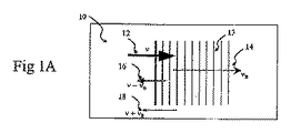
図1Aおよび図1Bは、本発明によるブリルアン散乱の原理を実行に移す方法の代表的実施形態の代表的な適用例の説明図である。
例えば、周波数V=ω/2πを有する単色性ポンプ光は検査中の媒質へ入射する。
音響波の典型的な生成は、量子力学的な真空の揺らぎに起因する種光子によって開始される。
単位周波数帯域幅当り1つの種光子が存在しうる。
1A and 1B are illustrations of a typical application of a representative embodiment of a method for implementing the principles of Brillouin scattering according to the present invention.
For example, monochromatic pump light having a frequency V = ω / 2π is incident on a medium under inspection.
Typical generation of acoustic waves is initiated by seed photons due to quantum mechanical vacuum fluctuations.
There can be one seed photon per unit frequency bandwidth.
ポンプ並びに種フォトン(光子)は、相互に干渉し、熱或いは電気歪効果により媒質中に機械的応力変調を惹起する。
この応力変調が媒質中で特性音響フォノン・モードの1つと位相整合がとれた場合には、対応する音響フォノンはコヒーレント過程により効率よく増強される。
励起された音響フォノンは媒質を屈折率変調してフォノンの非弾性散乱を次々に惹起する。
フォトンのエネルギおよび運動量は、非弾性散乱過程によって変調される。
散乱されたフォトンの周波数シフトの大きさは、実質的に或いは概ね音響フォノンのそれと等しい。
この典型的な手順は「ブリルアン現象」または「ブリルアン散乱」と呼ばれる。
ストークスおよび反ストークス成分が発生するが、典型的にはストークス・ブリルアン成分(即ち周波数下方シフト)が支配的である。
The pump and seed photons (photons) interfere with each other and cause mechanical stress modulation in the medium due to thermal or electrostrictive effects.
When this stress modulation is phase matched with one of the characteristic acoustic phonon modes in the medium, the corresponding acoustic phonon is efficiently enhanced by a coherent process.
The excited acoustic phonons modulate the refractive index of the medium and cause inelastic scattering of phonons one after another.
Photon energy and momentum are modulated by inelastic scattering processes.
The magnitude of the frequency shift of the scattered photons is substantially or approximately equal to that of the acoustic phonon.
This typical procedure is called "Brillouin phenomenon" or "Brillouin scattering".
Stokes and anti-Stokes components occur, but typically the Stokes-Brillouin component (ie, frequency downshift) is dominant.
ポンプ散乱光と音響波との間の代表的な位相整合条件を次式で表す。

位相整合フォノンの周波数、即ちポンプと散乱フォトンとの差は次式で与えられる。
![]()
The frequency of the phase matching phonon, i.e., the difference between the pump and scattered photons is given by:
![]()
ここにVAは媒質中の音響フォノン・モード(即ち、音響波)の速度を表し、θはポンプと散乱フォトン(即ち、光波)間の角度を表す。
式(3)に示すように、ブリルアン・シフトは音響速度に従って増加する。
固体媒質中では、音響速度は弾性率の平方根に比例する。
2波が反対方向へ伝播する場合、θ=180°であって、ブリルアン・シフトの強度は最大になる。
Here, V A represents the velocity of the acoustic phonon mode (ie, acoustic wave) in the medium, and θ represents the angle between the pump and scattered photons (ie, light wave).
As shown in equation (3), the Brillouin shift increases with acoustic velocity.
In a solid medium, the acoustic velocity is proportional to the square root of the elastic modulus.
If the two waves propagate in opposite directions, θ = 180 ° and the intensity of the Brillouin shift is maximized.
例えば、図1Aは、本発明の代表的な実施形態を実行することにより得られる後方ブリルアン散乱効果の解説図である。
周波数νのポンプ波12が媒質10へ入力して、波頭13で表された音響波および音響周波数νBに相当する波ベクトル14を発生する。位相整合条件を満たすブリルアン散乱光16は周波数ν−νBを有する。例えば、サンプル内に多数の音響モ−ドがある場合、ブリルアン散乱光のスペクトルは、いずれもサンプルの力学的特性に関係する周波数、大きさ及びスペクトル幅により特徴付けられた複数の線により構成されるものとなる。
媒質10が光学的に透明である場合、ポンプ光の周波数よりも高い周波数を有する反ストークス・ブリルアン光18は発生しない。
生体組織のような不透明な媒質中では、この光は、非常に弱い非弾性ブリルアン散乱またはラマン散乱に加えて、強い弾性ミー散乱またはレーリ散乱により散乱される。
弾性的に散乱され、無作為的に各方向へ拡散された光は相互に干渉し、その結果、検出が可能な反ストークス・ブリルアン光となる。
For example, FIG. 1A is an illustration of the back Brillouin scattering effect obtained by implementing an exemplary embodiment of the present invention.
A
When the medium 10 is optically transparent, the anti-Stokes Brillouin light 18 having a frequency higher than that of the pump light is not generated.
In opaque media such as biological tissue, this light is scattered by strong elastic Mie scattering or Rayleigh scattering in addition to very weak inelastic Brillouin or Raman scattering.
Light that is elastically scattered and randomly diffused in each direction interferes with each other, resulting in anti-Stokes Brillouin light that can be detected.
最初に音響波が与えられた場合、散乱光の存在によりブリルアン現象が加速される。
この散乱光は、ポンプ光とコヒーレントであって、共振音響波を増幅し、次いで、ブリルアン散乱を次々に増進させる。
この正帰還は強ブリルアン・シフト散乱光、即ち「誘導ブリルアン散乱」と呼ばれる手順をもたらす。長い光ファイバ中では数10mWの非常に弱い出力で発生し、次式により与えられるブリルアン利得を特徴とする。
This scattered light is coherent with the pump light and amplifies the resonant acoustic wave, which in turn enhances Brillouin scattering.
This positive feedback results in a procedure called strong Brillouin shift scattered light, or “stimulated Brillouin scattering”. It occurs with a very weak output of several tens of mW in a long optical fiber, and is characterized by a Brillouin gain given by
図1Bは、不透明媒質22における本発明の代表的な実施形態によるブリルアン相互作用の別の適用例であって、この相互作用は周波数の差がΔνである2種類のポンプ波20,21により開始される。
ポンプ波の代表的な弾性散乱は、多方向へ伝播する音響波(フォノン)の励起を惹起する。
図1Bの代表的な説明図では、2波のみが前方23および後方24へ伝播する。
この結果として生じたブリルアン散乱光は、ストークス26および反ストークス28を含む複数のスペクトル線を有する。
本発明によるこの代表的な適用例は、反ストークス線の発生を増強するために用いられる。
例えば、最大ブリルアン効率は、周波数の差がこの方法で発生した音響波(フォノン)の少なくとも1波の周波数に実質的に整合する場合に達成される。
FIG. 1B is another application of Brillouin interaction according to an exemplary embodiment of the present invention in an opaque medium 22, which interaction is initiated by two types of pump waves 20, 21 with a frequency difference of Δν. Is done.
Typical elastic scattering of pump waves causes excitation of acoustic waves (phonons) propagating in multiple directions.
In the representative illustration of FIG. 1B, only two waves propagate to the front 23 and the rear 24.
The resulting Brillouin scattered light has a plurality of spectral lines including Stokes 26 and
This exemplary application according to the present invention is used to enhance the generation of anti-Stokes lines.
For example, maximum Brillouin efficiency is achieved when the frequency difference substantially matches the frequency of at least one acoustic wave (phonon) generated in this way.
ブリルアン散乱の効率は光強度に比例するため、ポンプ・ビームをサンプルに集束させることによりさらなる高い効率が得られる。
集束させることにより、さらに優れた空間識別能力、即ち分解能が得られる。
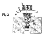
図2は、本発明の代表的な実施形態による、ポンプ・ビーム32をサンプル34へ集束させかつ後方伝播ブリルアン散乱光36を集光させるための対物レンズ30の代表的な用途の説明図である。
このような代表的な検出のスキームは「エピ構成」と呼ばれる。
例えば、図2は弾性的に散乱され拡散された波40とともに前方へ伝播する関連波38を示すものである。
レンズの開口数内の弾性散乱光の一部分もまた集光される。
ブリルアン過程は位相共役であるため、小開口数対物レンズを用いても後方ブリルアン散乱を効率よく集光することができる。
Since the efficiency of Brillouin scattering is proportional to the light intensity, higher efficiency can be obtained by focusing the pump beam on the sample.
By focusing, an even better spatial discrimination capability, i.e. resolution, is obtained.
FIG. 2 is an illustration of an exemplary application of an
Such a typical detection scheme is called “epi-configuration”.
For example, FIG. 2 shows a related wave 38 propagating forward with an elastically scattered and diffused
A portion of the elastically scattered light within the numerical aperture of the lens is also collected.
Since the Brillouin process is phase conjugate, backward Brillouin scattering can be efficiently collected even if a small numerical aperture objective lens is used.
ブリルアン分光法はブリルアン散乱光のスペクトルを測定することができる技術であって、これにより媒質の固有音響フォノンの特性を知ることができる。
ブリルアン・スペクトルは、(例えばその最も簡単な形で)式(1)および式(2)で表された位相シフト条件を通して媒質の力学的特性と密接に結びついている。
Brillouin spectroscopy is a technique that can measure the spectrum of Brillouin scattered light, whereby the characteristics of the intrinsic acoustic phonons of the medium can be known.
The Brillouin spectrum is closely linked to the mechanical properties of the medium through the phase shift conditions expressed in equations (1) and (2) (for example in its simplest form).
本発明の代表的な実施形態の重要な特性の1つはイメージ生成機能である。
予め定められた即ち計算値が与えられた変換テーブルを用いて、ブリルアン・スペクトルの空間的変化がイメージとして表わされる。
イメージを生成するために、ポンプ・ビーム或いはプローブ・ビームはサンプルを横断して走査され、かつ/またはこのサンプルは併進移動させられる。
図3Aおよび図3Bは、ガルバノメータ並びに回転カテーテルを用いる本発明の代表的実施形態による適用例であって、2種類のビームの個別走査を図解するものである。
図3Aに示されているように、ポンプ波60はガルバノメータ搭載ミラー62により反射され、対物レンズ64により媒質68へ集束する。
エピ・モードで対物レンズ64により集光された光は後方散乱成分70とブリルアン・シフト成分72とで構成される。
ポリゴンミラー・スキャナやMEMSミラー等の別の簡易スキャナを用いることもできるが、使用できるスキャナはこれらに限るものではない。
図3Bは、例えば管腔イメージングに利用するために光ファイバ・カテーテル或いは内視鏡を基本とする本発明に従う装置の代表的実施形態を用いたビーム走査応用を表す。
例えば、カテーテルは単一モードファイバ80、集束用レンズ82、プリズム84、ドライブシャフト86および保護被覆88を有することができる。
静止被覆88の内部で回転するカテーテル・コアーは、光ビーム90を螺旋を描くように用いて組織92を横断して走査する。
One important characteristic of the exemplary embodiment of the present invention is the image generation function.
The spatial variation of the Brillouin spectrum is represented as an image using a conversion table which is predetermined or given a calculated value.
To generate an image, the pump beam or probe beam is scanned across the sample and / or the sample is translated.
FIGS. 3A and 3B illustrate an application according to an exemplary embodiment of the present invention using a galvanometer and a rotating catheter, illustrating separate scanning of the two types of beams.
As shown in FIG. 3A, the pump wave 60 is reflected by a galvanometer mounted mirror 62 and focused on a medium 68 by an objective lens 64.
The light condensed by the objective lens 64 in the epi mode is composed of a
Other simple scanners such as a polygon mirror scanner and a MEMS mirror can be used, but the scanners that can be used are not limited to these.
FIG. 3B represents a beam scanning application using an exemplary embodiment of an apparatus according to the present invention based on a fiber optic catheter or endoscope, for example for use in lumen imaging.
For example, the catheter can have a single mode fiber 80, a focusing lens 82, a prism 84, a drive shaft 86 and a protective coating 88.
A catheter core that rotates within the stationary sheath 88 scans across the tissue 92 using a
ポンプ・ビームのサンプル上のビーム・サイズは空間分解能を決定するものである。
粗い空間分解能で十分であれば、平行光線を用いることができる。
図4Aに示すように、小開口数(NA)を有する対物レンズ100を実装した場合、横方向分解能は劣化する。
軸方向干渉長が長くかつ境界が明瞭である場合(図4A)、図4Bに示すように大NA対物レンズ102は一層優れた横方向および軸方向分解能をもたらす。
大NAを用いればブリルアン相互干渉長は短くなり、また大きな立体角にわたり位相整合がとれる。
両ケースにおいて、後方伝播ブリルアン光はエピ・コンフィグレーションにおいて検出される。
図4Cは、少なくとも2組の対物レンズ104、106を用いた本発明による方法及び装置の代表的実施形態の別の代表的な実行法を表す。
しかしながら、このスキームは厚い組織或いは生体内応用には適していない。
The beam size on the pump beam sample determines the spatial resolution.
If a coarse spatial resolution is sufficient, parallel rays can be used.
As shown in FIG. 4A, when the
When the axial interference length is long and the boundary is clear (FIG. 4A), the large NA
When a large NA is used, the Brillouin mutual interference length is shortened and phase matching can be achieved over a large solid angle.
In both cases, backward propagating Brillouin light is detected in the epi configuration.
FIG. 4C represents another exemplary implementation of an exemplary embodiment of the method and apparatus according to the present invention using at least two sets of
However, this scheme is not suitable for thick tissue or in vivo applications.
図5は本発明による装置の代表的な実施形態のブロック図を表す。
例えば、図5の装置は可視光或いは赤外光を放射する単色レーザが好適な光源110、およびビーム・スプリッタ114、ビーム・スキャナ116および対物レンズ118を通してサンプル112へ照射されるポンプ・ビーム/波111を含んでいる。
光源110は、限定するものではないが、中心波長が0.5〜1.8μmの間にあり、かつ典型的には100MHz未満の狭い線幅を持ちフォノンの寿命よりも長い時間コヒーレンスをもたらす連続波単一周波数レーザである。
別の好適な光源の種類は、Q−スイッチ単一周波数レーザである。
そのパルス繰り返し速度は1〜100KHzの範囲にあり、パルス持続時間は10ns〜1μsの範囲にある。
Q−スイッチポンプ光は、同じ平均出力レベルで連続光より強度が高いため、連続光に比べてブリルアン発生効率はさらに高い。
光源110は1種類以上の周波数成分を搬送するための光学装置を利用或いは具備することができる(図8Aおよび8Bに図示)。
ビーム・スキャンの横方向ステップ・サイズは、サンプル112中のポンプ・ビーム/波111の焦点サイズとほぼ同じである。
FIG. 5 represents a block diagram of an exemplary embodiment of an apparatus according to the present invention.
For example, the apparatus of FIG. 5 has a
The
Another suitable light source type is a Q-switched single frequency laser.
The pulse repetition rate is in the range of 1-100 KHz and the pulse duration is in the range of 10 ns-1 μs.
Since the Q-switch pump light has higher intensity than continuous light at the same average output level, the Brillouin generation efficiency is higher than that of continuous light.
The
The beam scan lateral step size is approximately the same as the focus size of the pump beam / wave 111 in the
サンプル112からもたらされた対物レンズ118により集光された散乱光120は、弾性および非弾性散乱の両散乱に由来するものである。
散乱光のスペクトルは、例えば走査フィルター、エタロン、仮想干渉計位相アレー、或いは分光計などのスペクトル選択性装置120を用いて測定される。
技術的に、ファブリー・ペロー干渉計を含む様々な走査フィルターが知られているが、フィルターはこれに限るものではない。
例えば、ブリルアン・シフトは数十GHzに及ぶ。
代表的なファブリー・ペロー走査型干渉計は50GHzの自由スペクトル・レンジを持ち精緻度は1000である。
スペクトルで選択されたフォトンは、次いで検出器122(例えば、光電子増倍管、アバランシ・フォトダイオードあるいは電荷結合素子アレー)で電気信号に変換される。
The
The spectrum of the scattered light is measured using a
Various scanning filters are known in the art, including a Fabry-Perot interferometer, but the filters are not limited to this.
For example, the Brillouin shift extends over tens of GHz.
A typical Fabry-Perot scanning interferometer has a free spectral range of 50 GHz and a precision of 1000.
The photons selected in the spectrum are then converted into electrical signals by a detector 122 (eg, a photomultiplier tube, avalanche photodiode or charge coupled device array).
光ファイバ・ヘテロダイン干渉計を用いた本発明の別の代表的な実施形態を図6Aおよび図6Bのブロック図に示す。
図6Aにおいて、単一周波数レーザ150が代表的な分割比約90対10を有する光ファイバ・ビーム・スプリッタ152に結合されている。
サンプル・アーム154と呼ばれる一光路はサーキュレータ158を経由してビーム・スキャナ156に接続されており、また、レファレンス・アーム170と呼ばれる別の光路は、光−音響或いは光−電気変調器等の周波数シフタ172を有している。
サンプル・アーム154およびレファレンス・アーム170はともに、例えば同じ分割比で、別の光ファイバ・ビーム・スプリッタ180に接続される。
サンプル・アーム154中の後方散乱光と参照アーム170中の周波数シフト参照光との間の干渉信号は、二重平衡受信機182で測定され、コンピュータ184を用いて処理される。
図6Aに示すように、周波数シフタ172が散乱光と参照光との間のビート周波数を低減させるために用いられ、偏光コントローラ174もまた利用される。
本発明の別の代表的な実施形態では、電気的スペクトル・アナライザはコンピュータ184に置き代わるか或いはこれを補完する。
別の方法として、ブリルアン・スペクトルは、シフタ172により周波数シフトの大きさに同調させ、また狭帯域幅検出器182を用いてビート(唸り)信号を検出して測定される。
Another exemplary embodiment of the present invention using a fiber optic heterodyne interferometer is shown in the block diagrams of FIGS. 6A and 6B.
In FIG. 6A, a single frequency laser 150 is coupled to a fiber
One optical path, called sample arm 154, is connected to beam scanner 156 via circulator 158, and another optical path, called
Both sample arm 154 and
The interference signal between the backscattered light in the sample arm 154 and the frequency shifted reference light in the
As shown in FIG. 6A, a frequency shifter 172 is used to reduce the beat frequency between the scattered light and the reference light, and a
In another exemplary embodiment of the present invention, the electrical spectrum analyzer replaces or supplements
Alternatively, the Brillouin spectrum is measured by tuning to the magnitude of the frequency shift by shifter 172 and detecting a beat signal using narrow bandwidth detector 182.
図6Bは、周波数差が同調可能な2種類の単色レーザ200および202を用いた本発明のさらなる代表的実施形態による別の代表的構成のブロック図を表す。
第1のレーザ200はポンプ波を搬送するためにサンプル・アーム210に結合されている。
第2のレーザ202は、所定値だけポンプ光源の周波数からずれた周波数を有する参照光を供給するための局部発信器として働く。
局部発信器の周波数は、ブリルアン信号光の1つの周波数と近く、そのビート周波数は検出器220により測定される。
例えば、ポンプ光源200および局部発信器202の線幅は、散乱光と参照光との間の時間コヒーレンシーを達成するために十分に狭くする必要があり、通常は100KHz未満である。
FIG. 6B represents a block diagram of another exemplary configuration according to a further exemplary embodiment of the present invention using two monochromatic lasers 200 and 202 with tunable frequency differences.
The first laser 200 is coupled to the
The second laser 202 serves as a local oscillator for supplying reference light having a frequency that deviates from the frequency of the pump light source by a predetermined value.
The frequency of the local oscillator is close to one frequency of the Brillouin signal light, and the beat frequency is measured by the detector 220.
For example, the line widths of the pump light source 200 and the local oscillator 202 need to be sufficiently narrow to achieve temporal coherency between the scattered light and the reference light, and are typically less than 100 KHz.
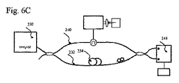
本発明はモード・ホップのない外部共振器型半導体レーザ、温度同調分布帰還型レーザ、および共振器変調固体型レーザのいずれかが推奨される周波数掃引型レーザ230に基づくものであって、図6Cは、この発明に従う装置によるさらに別の実施形態のブロック図を図示するものである。
レファレンス・アーム232は、一定および/または参照アーム232とサンプル・アーム240との長さの差により制御される可変の光遅延をもたらす遅延線234を有している。
2組のアームの不一致長は次式により選ばれる。
このような選択によって検出器244で検出された電気的ビート周波数は、音響周波数に比べて十分に小さい。
他方、2組のアーム232と240との経路長が実質的に整合した場合には、このような代表的な測定技術は光周波数領域反射率測定法に類似したものとなる。
波長の関数として測定された干渉信号は、弾性後方散乱係数の軸方向プロファイルを生成するためにフーリエ変換を用いて処理される。
同様にして、長さの適当な不整合を用い、同様な信号処理によりブリルアン散乱係数の軸方向プロファイルが生成される。
The present invention is based on a frequency swept laser 230 in which any of an external cavity type semiconductor laser without a mode hop, a temperature tuned distributed feedback laser, and a cavity-modulated solid state laser is recommended. FIG. 4 illustrates a block diagram of yet another embodiment of an apparatus according to the present invention.
The
The mismatch lengths of the two sets of arms are selected by the following formula.
The electrical beat frequency detected by the detector 244 by such selection is sufficiently smaller than the acoustic frequency.
On the other hand, if the path lengths of the two
The interference signal measured as a function of wavelength is processed using a Fourier transform to generate an axial profile of the elastic backscatter coefficient.
Similarly, an axial profile of the Brillouin scattering coefficient is generated with similar signal processing using an appropriate length mismatch.
図7A〜図7Dは、2種類の異なる周波数成分からなるポンプ波を発生できる本発明の代表的な実施形態による2組の異なる代表的光源装置の多様なステージを描写するものである。
このような2周波数ポンプ波に基づくブリルアン分光法が図1Bに図解されており、また本明細書中に上述されている。
例えば、図7Aにおいて、適切な直流バイアスのかかった光電変調器は、単色レーザ入力から2組の側波帯を生成する。
図7Bにおいて、2種類の低ドリフト単色レーザがビーム・コンバイナ270に結合されている。
エピ・コンフィグレーションでは、図7Cに示すように、結合されたポンプ波は対物レンズ282を通してサンプル280へ搬送される。
図7Dに示すように、伝送構造において、2種類の周波数成分の一方を反対方向へ送出するために第2の対物レンズ284が用いられる。
7A-7D depict various stages of two different exemplary light source devices according to an exemplary embodiment of the present invention that can generate a pump wave composed of two different frequency components.
Brillouin spectroscopy based on such a dual frequency pump wave is illustrated in FIG. 1B and is described above in this specification.
For example, in FIG. 7A, an appropriate DC biased photoelectric modulator generates two sets of sidebands from a monochromatic laser input.
In FIG. 7B, two types of low drift monochromatic lasers are coupled to the
In the epi configuration, the combined pump wave is conveyed through the objective lens 282 to the
As shown in FIG. 7D, a second
図8Aおよび図8Bは、本発明の実施形態によりサンプルの異なる2部位から取得された代表的なブリルアン・スペクトルを図示するものである。
例えば、これらの図において、νBと表された2種類のスペクトルの差は、2部位間の剛性の差を示している。
(図8Cに示す)イメージ300は、グレー・スケール・ルックアップ・テーブル310および/または擬似カラー・ルックアップ・テーブルを用いて、ブリルアン信号の測定値に基づいて作成される。
ルックアップ・テーブル310およびルックアップ・テーブル320は、1つ以上の特定のブリルアン・ピークの大きさ並びに/または周波数に基づくものである。
8A and 8B illustrate representative Brillouin spectra acquired from two different parts of a sample according to embodiments of the present invention.
For example, in these figures, the difference between the two types of spectra expressed as ν B indicates the difference in stiffness between the two sites.
An image 300 (shown in FIG. 8C) is created based on Brillouin signal measurements using a gray scale look-up table 310 and / or a pseudo color look-up table.
Lookup table 310 and lookup table 320 are based on the size and / or frequency of one or more specific Brillouin peaks.
図9Aおよび図9Bは、本発明の代表的な実施形態による光ファイバ・カテーテル420または内視鏡430を用いたブリルアン内視鏡検査の人体410への臨床応用を考えうる範囲で図解するものである。
カテーテル420は、図3Bに類似の構造を持ち、また上記内視鏡430にはMEMSスキャナのような2軸XYビーム走査型アクチュエータが用いられる。
ブリルアン顕微鏡検査法の潜在用途は多数あり、生体力学的特性、癌診断、腫瘍限界決定、創傷回復モニタリング、組織焼灼モニタリング、およびヒト組織工学などに基づいた組織の特性化が含まれる。
FIGS. 9A and 9B illustrate the clinical application of the Brillouin endoscopy using the
The
There are many potential uses for Brillouin microscopy, including tissue characterization based on biomechanical characteristics, cancer diagnosis, tumor margin determination, wound recovery monitoring, tissue ablation monitoring, and human tissue engineering.
前述の説明は単に本発明の原理を例示したに過ぎない。
本明細書の説明を考慮して、記載された実施形態に種々の変更や改変を加えることは、当業者にとって明白である。
実際に、本発明の代表的な実施形態による装置、システム、および方法は、どのようなOCTシステム、OFDIシステム、スペクトル領域OCT(SD−OCT)システム、または他のイメージングシステム、例えば、2004年9月8日出願の国際特許出願第PCT/US2004/029148号、2005年11月2日出願の米国特許出願第11/266,779号、および2004年7月9日出願の米国特許出願第10/501,276号に記載されているものに対しても使用可能であり、これらの開示の全てを本明細書の一部として援用する。
従って、当業者にとっては、本明細書に明確に提示又は説明されていなくとも、本発明の原理を具現化する数多くのシステム、装置、及び方法に工夫を凝らすことが可能であり、これは本発明の趣旨と範囲内に含まれることが理解されるであろう。
さらに、上述の明細書に前記の先行技術の知識が明示的に援用されていない範囲においても、その全体を明示的に本明細書に援用する。
本明細書で引用した上述の全ての文献は、その全体を本明細書の一部として援用する。
The foregoing description is merely illustrative of the principles of the present invention.
Various changes and modifications to the described embodiments will be apparent to those skilled in the art in view of the description herein.
Indeed, an apparatus, system, and method according to an exemplary embodiment of the present invention is suitable for any OCT system, OFDI system, spectral domain OCT (SD-OCT) system, or other imaging system, eg, 2004 9 International Patent Application No. PCT / US2004 / 029148, filed Nov. 8, U.S. Patent Application No. 11 / 266,779, filed Nov. 2, 2005, and U.S. Patent Application No. 10 /, filed Jul. 9, 2004. 501,276 can also be used and all of these disclosures are incorporated herein by reference.
Thus, those skilled in the art will be able to devise numerous systems, devices and methods that embody the principles of the present invention, even if not explicitly presented or described herein. It will be understood that it is within the spirit and scope of the invention.
Furthermore, the entire contents of the above-mentioned specification are expressly incorporated in the present specification even in a range where the above-mentioned prior art knowledge is not explicitly incorporated.
All of the above references cited herein are hereby incorporated by reference in their entirety.
Claims (25)
前記生体サンプルの少なくとも一部位に関係する情報を決定するために用いられる前記少なくとも1つの第2の電磁放射の少なくとも一部分を受信するように構成された少なくとも1つの第2の装置と、
前記生体サンプルを横断する前記少なくとも1つの第1の電磁放射が自動的に並進移動するように構成された少なくとも1つの第3の装置と、
前記少なくとも1つの第2の電磁放射に関するデータに基づいて前記生体サンプルの前記少なくとも一部位をイメージ化するように構成された少なくとも1つの第4の装置と、を備え、
前記少なくとも1つの第4の装置が、大開口数を有する少なくとも一枚のレンズを含み、前記少なくとも一枚のレンズが前記少なくとも1つの第1の電磁放射を集束させかつ前記少なくとも1つの第2の電磁放射を集光することを特徴とする装置。 Configured to provide at least one first electromagnetic radiation to the biological sample to provide at least one acoustic wave in the biological sample, and based on the at least one acoustic wave in the biological sample. At least one first device in which second electromagnetic radiation is generated;
At least one second device configured to receive at least a portion of the at least one second electromagnetic radiation used to determine information related to at least a portion of the biological sample;
At least one third device configured to automatically translate the at least one first electromagnetic radiation traversing the biological sample ;
At least one fourth device configured to image the at least a portion of the biological sample based on data relating to the at least one second electromagnetic radiation;
The at least one fourth device includes at least one lens having a large numerical aperture, the at least one lens focuses the at least one first electromagnetic radiation and the at least one second A device characterized in that it collects electromagnetic radiation .
前記生体の解剖学的サンプルの少なくとも一部分に関係する情報を決定するために前記少なくとも1つの第2の電磁放射の少なくとも一部分を受信するように構成された少なくとも1つの第2の装置と、
前記少なくとも1つの第2の電磁放射に関連するデータに基づく情報を解析するように構成された少なくとも1つの第3の装置と、
前記生体の解剖学的サンプルを横断する前記少なくとも1つの第1の電磁放射が自動的に並進移動するように構成された少なくとも1つの第4の装置と、
前記少なくとも1つの第2の電磁放射に関するデータに基づいて前記生体サンプルの前記少なくとも一部位をイメージ化するように構成された少なくとも1つの第5の装置と、を備え、
前記少なくとも1つの第1の電磁放射が少なくとも1つの第1の強度と少なくとも1つの第1の周波数を含み、前記少なくとも1つの第2の電磁放射が少なくとも1つの第2の強度と前記少なくとも1つの第1の周波数とは異なる少なくとも1つの第2の周波数とを含み、前記データが第2の強度または前記第1の周波数と前記第2の周波数との差に関係し、前記差がほぼ−100GHz〜100GHzの間にあること、
前記少なくとも1つの第5の装置が、大開口数を有する少なくとも一枚のレンズを含み、前記少なくとも一枚のレンズが前記少なくとも1つの第1の電磁放射を集束させかつ前記少なくとも1つの第2の電磁放射を集光することを特徴とする装置。 Configured to provide at least one first electromagnetic radiation to the biological anatomical sample to generate at least one acoustic wave within the biological anatomical sample, from the biological anatomical sample At least one first device that provides at least one second electromagnetic radiation based on the at least one acoustic wave;
At least one second device configured to receive at least a portion of the at least one second electromagnetic radiation to determine information relating to at least a portion of the biological anatomical sample;
At least one third device configured to analyze information based on data related to the at least one second electromagnetic radiation;
At least one fourth device configured to automatically translate the at least one first electromagnetic radiation across the anatomical sample of the living body ;
And at least one fifth device configured to image the at least a portion of the biological sample based on data relating to the at least one second electromagnetic radiation;
The at least one first electromagnetic radiation includes at least one first intensity and at least one first frequency, and the at least one second electromagnetic radiation includes at least one second intensity and the at least one At least one second frequency different from the first frequency, wherein the data relates to a second intensity or a difference between the first frequency and the second frequency, the difference being approximately −100 GHz. Be between ~ 100GHz,
The at least one fifth device includes at least one lens having a large numerical aperture, the at least one lens focuses the at least one first electromagnetic radiation and the at least one second A device characterized in that it collects electromagnetic radiation .
The apparatus of claim 1, wherein the at least one first electromagnetic radiation is provided to a biological sample in a living body.
Applications Claiming Priority (3)
| Application Number | Priority Date | Filing Date | Title |
|---|---|---|---|
| US77191606P | 2006-02-08 | 2006-02-08 | |
| US60/771,916 | 2006-02-08 | ||
| PCT/US2007/061815 WO2007092911A2 (en) | 2006-02-08 | 2007-02-08 | Methods, arrangements and systems for obtaining information associated with an anatomical sample using optical microscopy |
Publications (2)
| Publication Number | Publication Date |
|---|---|
| JP2009525838A JP2009525838A (en) | 2009-07-16 |
| JP5519152B2 true JP5519152B2 (en) | 2014-06-11 |
Family
ID=38235242
Family Applications (1)
| Application Number | Title | Priority Date | Filing Date |
|---|---|---|---|
| JP2008554495A Active JP5519152B2 (en) | 2006-02-08 | 2007-02-08 | Device for acquiring information about anatomical samples using optical microscopy |
Country Status (4)
| Country | Link |
|---|---|
| US (4) | US9777053B2 (en) |
| EP (2) | EP3143926B1 (en) |
| JP (1) | JP5519152B2 (en) |
| WO (1) | WO2007092911A2 (en) |
Families Citing this family (79)
| Publication number | Priority date | Publication date | Assignee | Title |
|---|---|---|---|---|
| EP1434522B1 (en) | 2000-10-30 | 2010-01-13 | The General Hospital Corporation | Optical systems for tissue analysis |
| US9295391B1 (en) | 2000-11-10 | 2016-03-29 | The General Hospital Corporation | Spectrally encoded miniature endoscopic imaging probe |
| AT503309B1 (en) * | 2001-05-01 | 2011-08-15 | Gen Hospital Corp | DEVICE FOR DETERMINING ATHEROSCLEROTIC BEARING BY MEASURING OPTICAL TISSUE PROPERTIES |
| AU2004225188B2 (en) | 2003-03-31 | 2010-04-15 | The General Hospital Corporation | Speckle reduction in optical coherence tomography by path length encoded angular compounding |
| EP2030563A3 (en) | 2003-06-06 | 2009-03-25 | The General Hospital Corporation | Process and apparatus for a wavelength tuning source |
| EP2293031B8 (en) | 2003-10-27 | 2024-03-20 | The General Hospital Corporation | Method and apparatus for performing optical imaging using frequency-domain interferometry |
| JP4995720B2 (en) | 2004-07-02 | 2012-08-08 | ザ ジェネラル ホスピタル コーポレイション | Endoscopic imaging probe with double clad fiber |
| EP1782020B1 (en) | 2004-08-06 | 2012-10-03 | The General Hospital Corporation | Process, system and software arrangement for determining at least one location in a sample using an optical coherence tomography |
| US8208995B2 (en) | 2004-08-24 | 2012-06-26 | The General Hospital Corporation | Method and apparatus for imaging of vessel segments |
| WO2006024014A2 (en) | 2004-08-24 | 2006-03-02 | The General Hospital Corporation | Process, system and software arrangement for measuring a mechanical strain and elastic properties of a sample |
| JP4997112B2 (en) | 2004-09-29 | 2012-08-08 | ザ ジェネラル ホスピタル コーポレイション | Apparatus for transmitting at least one electromagnetic radiation and method of manufacturing the same |
| JP2008521516A (en) | 2004-11-29 | 2008-06-26 | ザ ジェネラル ホスピタル コーポレイション | Configuration, apparatus, endoscope, catheter, and method for performing optical image generation by simultaneously illuminating and detecting multiple points on a sample |
| EP2085929A1 (en) | 2005-04-28 | 2009-08-05 | The General Hospital Corporation | Evaluating optical coherence tomography information for an anatomical structure |
| EP1889037A2 (en) | 2005-06-01 | 2008-02-20 | The General Hospital Corporation | Apparatus, method and system for performing phase-resolved optical frequency domain imaging |
| KR101387454B1 (en) | 2005-08-09 | 2014-04-22 | 더 제너럴 하스피탈 코포레이션 | Apparatus, methods and storage medium for performing polarization-based quadrature demodulation in optical coherence tomography |
| EP2275026A1 (en) | 2005-09-29 | 2011-01-19 | The General Hospital Corporation | Arrangements and methods for providing multimodality microscopic imaging of one or more biological structures |
| US9087368B2 (en) | 2006-01-19 | 2015-07-21 | The General Hospital Corporation | Methods and systems for optical imaging or epithelial luminal organs by beam scanning thereof |
| WO2007084903A2 (en) | 2006-01-19 | 2007-07-26 | The General Hospital Corporation | Apparatus for obtaining information for a structure using spectrally-encoded endoscopy techniques and method for producing one or more optical arrangements |
| US7538859B2 (en) | 2006-02-01 | 2009-05-26 | The General Hospital Corporation | Methods and systems for monitoring and obtaining information of at least one portion of a sample using conformal laser therapy procedures, and providing electromagnetic radiation thereto |
| EP1983921B1 (en) | 2006-02-01 | 2016-05-25 | The General Hospital Corporation | Systems for providing electromagnetic radiation to at least one portion of a sample using conformal laser therapy procedures |
| WO2007101026A2 (en) | 2006-02-24 | 2007-09-07 | The General Hospital Corporation | Methods and systems for performing angle-resolved fourier-domain optical coherence tomography |
| WO2007133961A2 (en) | 2006-05-10 | 2007-11-22 | The General Hospital Corporation | Processes, arrangements and systems for providing frequency domain imaging of a sample |
| US8838213B2 (en) * | 2006-10-19 | 2014-09-16 | The General Hospital Corporation | Apparatus and method for obtaining and providing imaging information associated with at least one portion of a sample, and effecting such portion(s) |
| WO2008118781A2 (en) | 2007-03-23 | 2008-10-02 | The General Hospital Corporation | Methods, arrangements and apparatus for utilizing a wavelength-swept laser using angular scanning and dispersion procedures |
| US10534129B2 (en) | 2007-03-30 | 2020-01-14 | The General Hospital Corporation | System and method providing intracoronary laser speckle imaging for the detection of vulnerable plaque |
| WO2009137701A2 (en) | 2008-05-07 | 2009-11-12 | The General Hospital Corporation | System, method and computer-accessible medium for tracking vessel motion during three-dimensional coronary artery microscopy |
| US8861910B2 (en) | 2008-06-20 | 2014-10-14 | The General Hospital Corporation | Fused fiber optic coupler arrangement and method for use thereof |
| WO2010009136A2 (en) | 2008-07-14 | 2010-01-21 | The General Hospital Corporation | Apparatus and methods for color endoscopy |
| GB0818775D0 (en) * | 2008-10-13 | 2008-11-19 | Isis Innovation | Investigation of physical properties of an object |
| JP5731394B2 (en) | 2008-12-10 | 2015-06-10 | ザ ジェネラル ホスピタル コーポレイション | System, apparatus and method for extending imaging depth range of optical coherence tomography through optical subsampling |
| US9615748B2 (en) | 2009-01-20 | 2017-04-11 | The General Hospital Corporation | Endoscopic biopsy apparatus, system and method |
| CN104134928A (en) | 2009-02-04 | 2014-11-05 | 通用医疗公司 | Apparatus and method for utilization of a high-speed optical wavelength tuning source |
| BR112012001042A2 (en) | 2009-07-14 | 2016-11-22 | Gen Hospital Corp | fluid flow measurement equipment and method within anatomical structure. |
| EP2485641A4 (en) * | 2009-10-06 | 2015-10-14 | Gen Hospital Corp | Apparatus and methods for imaging particular cells including eosinophils |
| DK2542154T3 (en) | 2010-03-05 | 2020-11-23 | Massachusetts Gen Hospital | APPARATUS FOR PROVIDING ELECTROMAGNETIC RADIATION TO A SAMPLE |
| US9069130B2 (en) | 2010-05-03 | 2015-06-30 | The General Hospital Corporation | Apparatus, method and system for generating optical radiation from biological gain media |
| WO2011150069A2 (en) | 2010-05-25 | 2011-12-01 | The General Hospital Corporation | Apparatus, systems, methods and computer-accessible medium for spectral analysis of optical coherence tomography images |
| EP2575597B1 (en) | 2010-05-25 | 2022-05-04 | The General Hospital Corporation | Apparatus for providing optical imaging of structures and compositions |
| US10285568B2 (en) | 2010-06-03 | 2019-05-14 | The General Hospital Corporation | Apparatus and method for devices for imaging structures in or at one or more luminal organs |
| JP5883018B2 (en) | 2010-10-27 | 2016-03-09 | ザ ジェネラル ホスピタル コーポレイション | Apparatus, system, and method for measuring blood pressure within at least one blood vessel |
| US9330092B2 (en) | 2011-07-19 | 2016-05-03 | The General Hospital Corporation | Systems, methods, apparatus and computer-accessible-medium for providing polarization-mode dispersion compensation in optical coherence tomography |
| US10241028B2 (en) | 2011-08-25 | 2019-03-26 | The General Hospital Corporation | Methods, systems, arrangements and computer-accessible medium for providing micro-optical coherence tomography procedures |
| GB201116518D0 (en) | 2011-09-23 | 2011-11-09 | Isis Innovation | Investigation of physical properties of an object |
| EP2769491A4 (en) | 2011-10-18 | 2015-07-22 | Gen Hospital Corp | Apparatus and methods for producing and/or providing recirculating optical delay(s) |
| JP2013205231A (en) * | 2012-03-28 | 2013-10-07 | Sumitomo Osaka Cement Co Ltd | Brillouin scattering microscope |
| WO2013148306A1 (en) | 2012-03-30 | 2013-10-03 | The General Hospital Corporation | Imaging system, method and distal attachment for multidirectional field of view endoscopy |
| US11490797B2 (en) | 2012-05-21 | 2022-11-08 | The General Hospital Corporation | Apparatus, device and method for capsule microscopy |
| WO2014031748A1 (en) | 2012-08-22 | 2014-02-27 | The General Hospital Corporation | System, method, and computer-accessible medium for fabrication minature endoscope using soft lithography |
| US9968261B2 (en) | 2013-01-28 | 2018-05-15 | The General Hospital Corporation | Apparatus and method for providing diffuse spectroscopy co-registered with optical frequency domain imaging |
| US10893806B2 (en) | 2013-01-29 | 2021-01-19 | The General Hospital Corporation | Apparatus, systems and methods for providing information regarding the aortic valve |
| WO2014121082A1 (en) | 2013-02-01 | 2014-08-07 | The General Hospital Corporation | Objective lens arrangement for confocal endomicroscopy |
| US10478072B2 (en) | 2013-03-15 | 2019-11-19 | The General Hospital Corporation | Methods and system for characterizing an object |
| WO2014186353A1 (en) | 2013-05-13 | 2014-11-20 | The General Hospital Corporation | Detecting self-interefering fluorescence phase and amplitude |
| US11452433B2 (en) | 2013-07-19 | 2022-09-27 | The General Hospital Corporation | Imaging apparatus and method which utilizes multidirectional field of view endoscopy |
| WO2015010133A1 (en) | 2013-07-19 | 2015-01-22 | The General Hospital Corporation | Determining eye motion by imaging retina. with feedback |
| ES2893237T3 (en) | 2013-07-26 | 2022-02-08 | Massachusetts Gen Hospital | Apparatus with a laser arrangement using optical scattering for applications in optical coherence tomography in the Fourier domain |
| WO2015105870A1 (en) | 2014-01-08 | 2015-07-16 | The General Hospital Corporation | Method and apparatus for microscopic imaging |
| US10736494B2 (en) | 2014-01-31 | 2020-08-11 | The General Hospital Corporation | System and method for facilitating manual and/or automatic volumetric imaging with real-time tension or force feedback using a tethered imaging device |
| US10228556B2 (en) | 2014-04-04 | 2019-03-12 | The General Hospital Corporation | Apparatus and method for controlling propagation and/or transmission of electromagnetic radiation in flexible waveguide(s) |
| EP3171766B1 (en) | 2014-07-25 | 2021-12-29 | The General Hospital Corporation | Apparatus for in vivo imaging and diagnosis |
| US10073006B2 (en) * | 2016-04-15 | 2018-09-11 | Viavi Solutions Inc. | Brillouin and rayleigh distributed sensor |
| US11206986B2 (en) * | 2016-08-15 | 2021-12-28 | New Jersey Institute Of Technology | Miniature quantitative optical coherence elastography using a fiber-optic probe with a fabry-perot cavity |
| JP2017000836A (en) * | 2016-09-27 | 2017-01-05 | Hoya株式会社 | Electronic endoscope apparatus |
| EP3538941A4 (en) | 2016-11-10 | 2020-06-17 | The Trustees of Columbia University in the City of New York | Rapid high-resolution imaging methods for large samples |
| US11241155B2 (en) * | 2017-01-27 | 2022-02-08 | The Regents Of The University Of California | Optical coherence tomography device for characterization of atherosclerosis with a 1.7 micron swept laser source |
| US10508985B2 (en) * | 2017-06-05 | 2019-12-17 | Northwestern University | Systems and methods for pump-probe spectroscopy |
| CA3072360A1 (en) | 2017-08-18 | 2019-02-21 | The General Hospital Corporation | Systems and methods for brillouin spectroscopy and imaging of tissues |
| US20190101489A1 (en) * | 2017-09-29 | 2019-04-04 | Michael John Darwin | Method and Apparatus for Simultaneously Measuring 3Dimensional Structures and Spectral Content of Said Structures |
| WO2019075376A1 (en) | 2017-10-13 | 2019-04-18 | The Research Foundation For The State University Of New York | Wavelength-division-multiplexing swept-source optical doppler tomography |
| MY196626A (en) * | 2017-10-17 | 2023-04-23 | Univ Malaya | Apparatus for Receiving Optical Signal |
| WO2019089531A1 (en) * | 2017-10-30 | 2019-05-09 | University Of Maryland, College Park | Brillouin imaging devices, and systems and methods employing such devices |
| JP7121606B2 (en) * | 2018-09-11 | 2022-08-18 | 浜松ホトニクス株式会社 | Optical measurement device |
| EP3881038A4 (en) * | 2018-11-14 | 2022-07-27 | Mstatt Llc | Method for optically detecting tooth mineralization |
| CN110045498A (en) * | 2019-04-01 | 2019-07-23 | 深圳市速腾聚创科技有限公司 | Light scanning apparatus and laser radar |
| WO2020247473A1 (en) * | 2019-06-03 | 2020-12-10 | The General Hospital Corporation | Systems and methods for stimulated brillouin microscopy |
| CN110426372B (en) * | 2019-07-16 | 2021-10-22 | 南昌航空大学 | Elastic modulus imaging detection method for frequency-sweeping Brillouin scatterer |
| US11422029B1 (en) | 2019-11-22 | 2022-08-23 | Intelon Optics, Inc. | Managing stability in spectroscopy measurement systems |
| US11519720B2 (en) * | 2020-10-12 | 2022-12-06 | Applied Materials Israel Ltd. | Depth profiling of semiconductor structures using picosecond ultrasonics |
| WO2023145191A1 (en) * | 2022-01-27 | 2023-08-03 | パナソニックIpマネジメント株式会社 | Measurement device |
Family Cites Families (516)
| Publication number | Priority date | Publication date | Assignee | Title |
|---|---|---|---|---|
| US188855A (en) * | 1877-03-27 | Improvement in can-jackets | ||
| US617286A (en) * | 1899-01-03 | galland | ||
| US101111A (en) * | 1870-03-22 | Improved holder for diamonds | ||
| US2339754A (en) | 1941-03-04 | 1944-01-25 | Westinghouse Electric & Mfg Co | Supervisory apparatus |
| US2738343A (en) * | 1951-02-28 | 1956-03-13 | Kellogg M W Co | Copolymer of trifluorochloroethylene and vinylidene fluoride |
| US3028114A (en) * | 1959-09-21 | 1962-04-03 | Kloeckner Werke Ag | Arrangement for coiling metal strip material |
| US3030816A (en) * | 1960-06-03 | 1962-04-24 | Specialties Dev Corp | Control device |
| US3090753A (en) | 1960-08-02 | 1963-05-21 | Exxon Research Engineering Co | Ester oil compositions containing acid anhydride |
| US3082105A (en) * | 1960-09-29 | 1963-03-19 | Bethlehem Steel Corp | Chrome silica brick |
| US3120137A (en) * | 1961-01-03 | 1964-02-04 | Ingersoll Rand Canada | Apparatus for forming varying shaped bores in hollow members |
| GB1257778A (en) | 1967-12-07 | 1971-12-22 | ||
| US3601480A (en) | 1968-07-10 | 1971-08-24 | Physics Int Co | Optical tunnel high-speed camera system |
| US3813613A (en) | 1972-01-24 | 1974-05-28 | Bell Telephone Labor Inc | Laser employing a metallic pentaphosphate |
| JPS4932484U (en) | 1972-06-19 | 1974-03-20 | ||
| US3872407A (en) * | 1972-09-01 | 1975-03-18 | Us Navy | Rapidly tunable laser |
| JPS584481Y2 (en) * | 1973-06-23 | 1983-01-26 | オリンパス光学工業株式会社 | Naishikiyoushiyahenkankogakkei |
| FR2253410A5 (en) * | 1973-12-03 | 1975-06-27 | Inst Nat Sante Rech Med | |
| US4002650A (en) * | 1973-12-10 | 1977-01-11 | The Standard Oil Company (Ohio) | Preparation of maleic anhydride from n-butane |
| US4077949A (en) * | 1973-12-28 | 1978-03-07 | Sloan-Kettering Institute For Cancer Research | Polypeptide hormones of the thymus |
| US3941121A (en) | 1974-12-20 | 1976-03-02 | The University Of Cincinnati | Focusing fiber-optic needle endoscope |
| US3983507A (en) | 1975-01-06 | 1976-09-28 | Research Corporation | Tunable laser systems and method |
| US3973219A (en) | 1975-04-24 | 1976-08-03 | Cornell Research Foundation, Inc. | Very rapidly tuned cw dye laser |
| US4030831A (en) | 1976-03-22 | 1977-06-21 | The United States Of America As Represented By The Secretary Of The Navy | Phase detector for optical figure sensing |
| US4072200A (en) * | 1976-05-12 | 1978-02-07 | Morris Fred J | Surveying of subterranean magnetic bodies from an adjacent off-vertical borehole |
| US4141362A (en) | 1977-05-23 | 1979-02-27 | Richard Wolf Gmbh | Laser endoscope |
| US4224929A (en) | 1977-11-08 | 1980-09-30 | Olympus Optical Co., Ltd. | Endoscope with expansible cuff member and operation section |
| DE2964775D1 (en) | 1978-03-09 | 1983-03-24 | Nat Res Dev | Measurement of small movements |
| GB2030313A (en) | 1978-06-29 | 1980-04-02 | Wolf Gmbh Richard | Endoscopes |
| FR2448728A1 (en) | 1979-02-07 | 1980-09-05 | Thomson Csf | ROTATING JOINT DEVICE FOR OPTICAL CONDUCTOR CONNECTION AND SYSTEM COMPRISING SUCH A DEVICE |
| US4263843A (en) * | 1979-07-30 | 1981-04-28 | Aluminum Company Of America | Method and apparatus for controlled removal of excess slurry from organic foam |
| US4300816A (en) | 1979-08-30 | 1981-11-17 | United Technologies Corporation | Wide band multicore optical fiber |
| US4295738A (en) | 1979-08-30 | 1981-10-20 | United Technologies Corporation | Fiber optic strain sensor |
| US4428643A (en) | 1981-04-08 | 1984-01-31 | Xerox Corporation | Optical scanning system with wavelength shift correction |
| US5065331A (en) | 1981-05-18 | 1991-11-12 | Vachon Reginald I | Apparatus and method for determining the stress and strain in pipes, pressure vessels, structural members and other deformable bodies |
| GB2106736B (en) | 1981-09-03 | 1985-06-12 | Standard Telephones Cables Ltd | Optical transmission system |
| US4483005A (en) * | 1981-09-24 | 1984-11-13 | Teradyne, Inc. | Affecting laser beam pulse width |
| US4479499A (en) * | 1982-01-29 | 1984-10-30 | Alfano Robert R | Method and apparatus for detecting the presence of caries in teeth using visible light |
| US5302025A (en) * | 1982-08-06 | 1994-04-12 | Kleinerman Marcos Y | Optical systems for sensing temperature and other physical parameters |
| US4601036A (en) | 1982-09-30 | 1986-07-15 | Honeywell Inc. | Rapidly tunable laser |
| HU187188B (en) | 1982-11-25 | 1985-11-28 | Koezponti Elelmiszeripari | Device for generating radiation of controllable spectral structure |
| CH663466A5 (en) * | 1983-09-12 | 1987-12-15 | Battelle Memorial Institute | METHOD AND DEVICE FOR DETERMINING THE POSITION OF AN OBJECT IN RELATION TO A REFERENCE. |
| US4639999A (en) | 1984-11-02 | 1987-02-03 | Xerox Corporation | High resolution, high efficiency I.R. LED printing array fabrication method |
| US4763977A (en) | 1985-01-09 | 1988-08-16 | Canadian Patents And Development Limited-Societe | Optical fiber coupler with tunable coupling ratio and method of making |
| US5318024A (en) * | 1985-03-22 | 1994-06-07 | Massachusetts Institute Of Technology | Laser endoscope for spectroscopic imaging |
| EP0590268B1 (en) | 1985-03-22 | 1998-07-01 | Massachusetts Institute Of Technology | Fiber Optic Probe System for Spectrally Diagnosing Tissue |
| DE3610165A1 (en) * | 1985-03-27 | 1986-10-02 | Olympus Optical Co., Ltd., Tokio/Tokyo | OPTICAL SCAN MICROSCOPE |
| US4607622A (en) | 1985-04-11 | 1986-08-26 | Charles D. Fritch | Fiber optic ocular endoscope |
| US4631498A (en) | 1985-04-26 | 1986-12-23 | Hewlett-Packard Company | CW Laser wavemeter/frequency locking technique |
| US4650327A (en) * | 1985-10-28 | 1987-03-17 | Oximetrix, Inc. | Optical catheter calibrating assembly |
| US5040889A (en) | 1986-05-30 | 1991-08-20 | Pacific Scientific Company | Spectrometer with combined visible and ultraviolet sample illumination |
| CA1290019C (en) | 1986-06-20 | 1991-10-01 | Hideo Kuwahara | Dual balanced optical signal receiver |
| US4770492A (en) | 1986-10-28 | 1988-09-13 | Spectran Corporation | Pressure or strain sensitive optical fiber |
| JPH0824665B2 (en) | 1986-11-28 | 1996-03-13 | オリンパス光学工業株式会社 | Endoscope device |
| US4744656A (en) | 1986-12-08 | 1988-05-17 | Spectramed, Inc. | Disposable calibration boot for optical-type cardiovascular catheter |
| US4751706A (en) | 1986-12-31 | 1988-06-14 | The United States Of America As Represented By The Secretary Of The Army | Laser for providing rapid sequence of different wavelengths |
| US4834111A (en) | 1987-01-12 | 1989-05-30 | The Trustees Of Columbia University In The City Of New York | Heterodyne interferometer |
| GB2209221B (en) | 1987-09-01 | 1991-10-23 | Litton Systems Inc | Hydrophone demodulator circuit and method |
| US5202931A (en) * | 1987-10-06 | 1993-04-13 | Cell Analysis Systems, Inc. | Methods and apparatus for the quantitation of nuclear protein |
| US4909631A (en) * | 1987-12-18 | 1990-03-20 | Tan Raul Y | Method for film thickness and refractive index determination |
| US4890901A (en) * | 1987-12-22 | 1990-01-02 | Hughes Aircraft Company | Color corrector for embedded prisms |
| US4892406A (en) | 1988-01-11 | 1990-01-09 | United Technologies Corporation | Method of and arrangement for measuring vibrations |
| FR2626367B1 (en) | 1988-01-25 | 1990-05-11 | Thomson Csf | MULTI-POINT FIBER OPTIC TEMPERATURE SENSOR |
| FR2626383B1 (en) | 1988-01-27 | 1991-10-25 | Commissariat Energie Atomique | EXTENDED FIELD SCAN AND DEPTH CONFOCAL OPTICAL MICROSCOPY AND DEVICES FOR CARRYING OUT THE METHOD |
| US4925302A (en) | 1988-04-13 | 1990-05-15 | Hewlett-Packard Company | Frequency locking device |
| US4998972A (en) * | 1988-04-28 | 1991-03-12 | Thomas J. Fogarty | Real time angioscopy imaging system |
| US5730731A (en) * | 1988-04-28 | 1998-03-24 | Thomas J. Fogarty | Pressure-based irrigation accumulator |
| US4905169A (en) * | 1988-06-02 | 1990-02-27 | The United States Of America As Represented By The United States Department Of Energy | Method and apparatus for simultaneously measuring a plurality of spectral wavelengths present in electromagnetic radiation |
| US5242437A (en) | 1988-06-10 | 1993-09-07 | Trimedyne Laser Systems, Inc. | Medical device applying localized high intensity light and heat, particularly for destruction of the endometrium |
| DE68928345T3 (en) | 1988-07-13 | 2008-03-06 | Optiscan Pty. Ltd., Toorak | CONFOKALES SCAN ENDOSCOPE |
| GB8817672D0 (en) | 1988-07-25 | 1988-09-01 | Sira Ltd | Optical apparatus |
| US5214538A (en) | 1988-07-25 | 1993-05-25 | Keymed (Medical And Industrial Equipment) Limited | Optical apparatus |
| US4868834A (en) | 1988-09-14 | 1989-09-19 | The United States Of America As Represented By The Secretary Of The Army | System for rapidly tuning a low pressure pulsed laser |
| DE3833602A1 (en) | 1988-10-03 | 1990-02-15 | Krupp Gmbh | SPECTROMETER FOR SIMULTANEOUS INTENSITY MEASUREMENT IN DIFFERENT SPECTRAL AREAS |
| US4940328A (en) | 1988-11-04 | 1990-07-10 | Georgia Tech Research Corporation | Optical sensing apparatus and method |
| US4966589A (en) | 1988-11-14 | 1990-10-30 | Hemedix International, Inc. | Intravenous catheter placement device |
| ATE133545T1 (en) | 1988-12-21 | 1996-02-15 | Massachusetts Inst Technology | METHOD FOR LASER-INDUCED FLUORESCENCE OF TISSUE |
| US5046501A (en) | 1989-01-18 | 1991-09-10 | Wayne State University | Atherosclerotic identification |
| US5085496A (en) * | 1989-03-31 | 1992-02-04 | Sharp Kabushiki Kaisha | Optical element and optical pickup device comprising it |
| US5317389A (en) | 1989-06-12 | 1994-05-31 | California Institute Of Technology | Method and apparatus for white-light dispersed-fringe interferometric measurement of corneal topography |
| US4984903A (en) | 1989-08-01 | 1991-01-15 | Gte Government Systems Corporation | Method of optically and remotely sensing subsurface water temperature |
| US4965599A (en) | 1989-11-13 | 1990-10-23 | Eastman Kodak Company | Scanning apparatus for halftone image screen writing |
| US5133035A (en) | 1989-11-14 | 1992-07-21 | Hicks John W | Multifiber endoscope with multiple scanning modes to produce an image free of fixed pattern noise |
| US4984888A (en) * | 1989-12-13 | 1991-01-15 | Imo Industries, Inc. | Two-dimensional spectrometer |
| KR930003307B1 (en) | 1989-12-14 | 1993-04-24 | 주식회사 금성사 | Three dimensional projector |
| US5251009A (en) | 1990-01-22 | 1993-10-05 | Ciba-Geigy Corporation | Interferometric measuring arrangement for refractive index measurements in capillary tubes |
| NL9000290A (en) * | 1990-02-07 | 1991-09-02 | Philips Nv | DISPLAY DEVICE. |
| DD293205B5 (en) | 1990-03-05 | 1995-06-29 | Zeiss Carl Jena Gmbh | Optical fiber guide for a medical observation device |
| US5039193A (en) | 1990-04-03 | 1991-08-13 | Focal Technologies Incorporated | Fibre optic single mode rotary joint |
| US5262644A (en) | 1990-06-29 | 1993-11-16 | Southwest Research Institute | Remote spectroscopy for raman and brillouin scattering |
| US5197470A (en) | 1990-07-16 | 1993-03-30 | Eastman Kodak Company | Near infrared diagnostic method and instrument |
| GB9015793D0 (en) | 1990-07-18 | 1990-09-05 | Medical Res Council | Confocal scanning optical microscope |
| US5845639A (en) | 1990-08-10 | 1998-12-08 | Board Of Regents Of The University Of Washington | Optical imaging methods |
| US5127730A (en) | 1990-08-10 | 1992-07-07 | Regents Of The University Of Minnesota | Multi-color laser scanning confocal imaging system |
| JP3104984B2 (en) | 1990-09-27 | 2000-10-30 | オリンパス光学工業株式会社 | Optical scanning device for tomographic image observation |
| JPH04135551A (en) | 1990-09-27 | 1992-05-11 | Olympus Optical Co Ltd | Optical three-dimensional image observing device |
| US5305759A (en) | 1990-09-26 | 1994-04-26 | Olympus Optical Co., Ltd. | Examined body interior information observing apparatus by using photo-pulses controlling gains for depths |
| US5241364A (en) | 1990-10-19 | 1993-08-31 | Fuji Photo Film Co., Ltd. | Confocal scanning type of phase contrast microscope and scanning microscope |
| US5250186A (en) | 1990-10-23 | 1993-10-05 | Cetus Corporation | HPLC light scattering detector for biopolymers |
| US5202745A (en) | 1990-11-07 | 1993-04-13 | Hewlett-Packard Company | Polarization independent optical coherence-domain reflectometry |
| US5275594A (en) * | 1990-11-09 | 1994-01-04 | C. R. Bard, Inc. | Angioplasty system having means for identification of atherosclerotic plaque |
| JP3035336B2 (en) | 1990-11-27 | 2000-04-24 | 興和株式会社 | Blood flow measurement device |
| US5228001A (en) | 1991-01-23 | 1993-07-13 | Syracuse University | Optical random access memory |
| US5784162A (en) | 1993-08-18 | 1998-07-21 | Applied Spectral Imaging Ltd. | Spectral bio-imaging methods for biological research, medical diagnostics and therapy |
| US6198532B1 (en) | 1991-02-22 | 2001-03-06 | Applied Spectral Imaging Ltd. | Spectral bio-imaging of the eye |
| US5293872A (en) | 1991-04-03 | 1994-03-15 | Alfano Robert R | Method for distinguishing between calcified atherosclerotic tissue and fibrous atherosclerotic tissue or normal cardiovascular tissue using Raman spectroscopy |
| US5956355A (en) | 1991-04-29 | 1999-09-21 | Massachusetts Institute Of Technology | Method and apparatus for performing optical measurements using a rapidly frequency-tuned laser |
| US6564087B1 (en) | 1991-04-29 | 2003-05-13 | Massachusetts Institute Of Technology | Fiber optic needle probes for optical coherence tomography imaging |
| US6111645A (en) | 1991-04-29 | 2000-08-29 | Massachusetts Institute Of Technology | Grating based phase control optical delay line |
| US6485413B1 (en) | 1991-04-29 | 2002-11-26 | The General Hospital Corporation | Methods and apparatus for forward-directed optical scanning instruments |
| US6134003A (en) | 1991-04-29 | 2000-10-17 | Massachusetts Institute Of Technology | Method and apparatus for performing optical measurements using a fiber optic imaging guidewire, catheter or endoscope |
| US6501551B1 (en) | 1991-04-29 | 2002-12-31 | Massachusetts Institute Of Technology | Fiber optic imaging endoscope interferometer with at least one faraday rotator |
| EP0581871B2 (en) | 1991-04-29 | 2009-08-12 | Massachusetts Institute Of Technology | Apparatus for optical imaging and measurement |
| US5748598A (en) | 1995-12-22 | 1998-05-05 | Massachusetts Institute Of Technology | Apparatus and methods for reading multilayer storage media using short coherence length sources |
| US5465147A (en) | 1991-04-29 | 1995-11-07 | Massachusetts Institute Of Technology | Method and apparatus for acquiring images using a ccd detector array and no transverse scanner |
| US5441053A (en) | 1991-05-03 | 1995-08-15 | University Of Kentucky Research Foundation | Apparatus and method for multiple wavelength of tissue |
| US5281811A (en) * | 1991-06-17 | 1994-01-25 | Litton Systems, Inc. | Digital wavelength division multiplex optical transducer having an improved decoder |
| US5208651A (en) | 1991-07-16 | 1993-05-04 | The Regents Of The University Of California | Apparatus and method for measuring fluorescence intensities at a plurality of wavelengths and lifetimes |
| AU2519892A (en) | 1991-08-20 | 1993-03-16 | Douglas C.B. Redd | Optical histochemical analysis, in vivo detection and real-time guidance for ablation of abnormal tissues using a raman spectroscopic detection system |
| DE4128744C1 (en) | 1991-08-29 | 1993-04-22 | Siemens Ag, 8000 Muenchen, De | |
| US5353790A (en) | 1992-01-17 | 1994-10-11 | Board Of Regents, The University Of Texas System | Method and apparatus for optical measurement of bilirubin in tissue |
| US5212667A (en) | 1992-02-03 | 1993-05-18 | General Electric Company | Light imaging in a scattering medium, using ultrasonic probing and speckle image differencing |
| US5217456A (en) | 1992-02-24 | 1993-06-08 | Pdt Cardiovascular, Inc. | Device and method for intra-vascular optical radial imaging |
| US5283795A (en) * | 1992-04-21 | 1994-02-01 | Hughes Aircraft Company | Diffraction grating driven linear frequency chirped laser |
| US5248876A (en) | 1992-04-21 | 1993-09-28 | International Business Machines Corporation | Tandem linear scanning confocal imaging system with focal volumes at different heights |
| US5486701A (en) | 1992-06-16 | 1996-01-23 | Prometrix Corporation | Method and apparatus for measuring reflectance in two wavelength bands to enable determination of thin film thickness |
| JP2976707B2 (en) | 1992-07-15 | 1999-11-10 | 三菱マテリアル株式会社 | Metal plastic composition |
| US5716324A (en) | 1992-08-25 | 1998-02-10 | Fuji Photo Film Co., Ltd. | Endoscope with surface and deep portion imaging systems |
| US5348003A (en) | 1992-09-03 | 1994-09-20 | Sirraya, Inc. | Method and apparatus for chemical analysis |
| US5772597A (en) | 1992-09-14 | 1998-06-30 | Sextant Medical Corporation | Surgical tool end effector |
| US5698397A (en) | 1995-06-07 | 1997-12-16 | Sri International | Up-converting reporters for biological and other assays using laser excitation techniques |
| WO1994012095A2 (en) | 1992-11-18 | 1994-06-09 | Spectrascience, Inc. | Apparatus for diagnostic imaging |
| US5383467A (en) | 1992-11-18 | 1995-01-24 | Spectrascience, Inc. | Guidewire catheter and apparatus for diagnostic imaging |
| JPH06222242A (en) * | 1993-01-27 | 1994-08-12 | Shin Etsu Chem Co Ltd | Optical fiber coupler and its manufacture |
| US5987346A (en) | 1993-02-26 | 1999-11-16 | Benaron; David A. | Device and method for classification of tissue |
| JP3112595B2 (en) * | 1993-03-17 | 2000-11-27 | 安藤電気株式会社 | Optical fiber strain position measuring device using optical frequency shifter |
| FI93781C (en) | 1993-03-18 | 1995-05-26 | Wallac Oy | Biospecific multiparametric assay method |
| DE4309056B4 (en) | 1993-03-20 | 2006-05-24 | Häusler, Gerd, Prof. Dr. | Method and device for determining the distance and scattering intensity of scattering points |
| US5485079A (en) | 1993-03-29 | 1996-01-16 | Matsushita Electric Industrial Co., Ltd. | Magneto-optical element and optical magnetic field sensor |
| DE4310209C2 (en) | 1993-03-29 | 1996-05-30 | Bruker Medizintech | Optical stationary imaging in strongly scattering media |
| SE501932C2 (en) | 1993-04-30 | 1995-06-26 | Ericsson Telefon Ab L M | Apparatus and method for dispersion compensation in a fiber optic transmission system |
| DE4314189C1 (en) | 1993-04-30 | 1994-11-03 | Bodenseewerk Geraetetech | Device for the examination of optical fibres made of glass by means of heterodyne Brillouin spectroscopy |
| US5424827A (en) | 1993-04-30 | 1995-06-13 | Litton Systems, Inc. | Optical system and method for eliminating overlap of diffraction spectra |
| US5454807A (en) | 1993-05-14 | 1995-10-03 | Boston Scientific Corporation | Medical treatment of deeply seated tissue using optical radiation |
| DE69418248T2 (en) | 1993-06-03 | 1999-10-14 | Hamamatsu Photonics Kk | Optical laser scanning system with Axikon |
| JP3234353B2 (en) | 1993-06-15 | 2001-12-04 | 富士写真フイルム株式会社 | Tomographic information reader |
| US5803082A (en) | 1993-11-09 | 1998-09-08 | Staplevision Inc. | Omnispectramammography |
| US5983125A (en) | 1993-12-13 | 1999-11-09 | The Research Foundation Of City College Of New York | Method and apparatus for in vivo examination of subcutaneous tissues inside an organ of a body using optical spectroscopy |
| US5450203A (en) | 1993-12-22 | 1995-09-12 | Electroglas, Inc. | Method and apparatus for determining an objects position, topography and for imaging |
| US5411016A (en) | 1994-02-22 | 1995-05-02 | Scimed Life Systems, Inc. | Intravascular balloon catheter for use in combination with an angioscope |
| US5590660A (en) | 1994-03-28 | 1997-01-07 | Xillix Technologies Corp. | Apparatus and method for imaging diseased tissue using integrated autofluorescence |
| DE4411017C2 (en) | 1994-03-30 | 1995-06-08 | Alexander Dr Knuettel | Optical stationary spectroscopic imaging in strongly scattering objects through special light focusing and signal detection of light of different wavelengths |
| TW275570B (en) | 1994-05-05 | 1996-05-11 | Boehringer Mannheim Gmbh | |
| US5459325A (en) | 1994-07-19 | 1995-10-17 | Molecular Dynamics, Inc. | High-speed fluorescence scanner |
| US6159445A (en) | 1994-07-20 | 2000-12-12 | Nycomed Imaging As | Light imaging contrast agents |
| EP1231496B1 (en) | 1994-08-18 | 2004-12-29 | Carl Zeiss AG | Optical coherence tomography assisted surgical apparatus |
| US5712165A (en) * | 1994-08-22 | 1998-01-27 | Beth Israel Hospital Administration | Method and apparatus for detecting hydrocarbon oxidation |
| US5491524A (en) | 1994-10-05 | 1996-02-13 | Carl Zeiss, Inc. | Optical coherence tomography corneal mapping apparatus |
| US5740808A (en) | 1996-10-28 | 1998-04-21 | Ep Technologies, Inc | Systems and methods for guilding diagnostic or therapeutic devices in interior tissue regions |
| US5817144A (en) | 1994-10-25 | 1998-10-06 | Latis, Inc. | Method for contemporaneous application OF laser energy and localized pharmacologic therapy |
| US6033721A (en) | 1994-10-26 | 2000-03-07 | Revise, Inc. | Image-based three-axis positioner for laser direct write microchemical reaction |
| US5566267A (en) | 1994-12-15 | 1996-10-15 | Ceram Optec Industries Inc. | Flat surfaced optical fibers and diode laser medical delivery devices |
| US5509417A (en) * | 1994-12-19 | 1996-04-23 | Hewlett Packard Company | Method and apparatus for phased array coupling ultrasonic energy into an acoustic waveguide wire |
| US5600486A (en) | 1995-01-30 | 1997-02-04 | Lockheed Missiles And Space Company, Inc. | Color separation microlens |
| US5648848A (en) | 1995-02-01 | 1997-07-15 | Nikon Precision, Inc. | Beam delivery apparatus and method for interferometry using rotatable polarization chucks |
| DE19506484C2 (en) * | 1995-02-24 | 1999-09-16 | Stiftung Fuer Lasertechnologie | Method and device for selective non-invasive laser myography (LMG) |
| RU2100787C1 (en) | 1995-03-01 | 1997-12-27 | Геликонов Валентин Михайлович | Fibre-optical interferometer and fiber-optical piezoelectric transducer |
| WO1996028212A1 (en) | 1995-03-09 | 1996-09-19 | Innotech Usa, Inc. | Laser surgical device and method of its use |
| US5526338A (en) | 1995-03-10 | 1996-06-11 | Yeda Research & Development Co. Ltd. | Method and apparatus for storage and retrieval with multilayer optical disks |
| US5697373A (en) | 1995-03-14 | 1997-12-16 | Board Of Regents, The University Of Texas System | Optical method and apparatus for the diagnosis of cervical precancers using raman and fluorescence spectroscopies |
| US5735276A (en) | 1995-03-21 | 1998-04-07 | Lemelson; Jerome | Method and apparatus for scanning and evaluating matter |
| DE19681304T1 (en) | 1995-03-24 | 1998-04-16 | Optiscan Pty Ltd | Confocal imaging system with optical fiber and variable close confocal control |
| US5565983A (en) | 1995-05-26 | 1996-10-15 | The Perkin-Elmer Corporation | Optical spectrometer for detecting spectra in separate ranges |
| US5621830A (en) | 1995-06-07 | 1997-04-15 | Smith & Nephew Dyonics Inc. | Rotatable fiber optic joint |
| US5785651A (en) | 1995-06-07 | 1998-07-28 | Keravision, Inc. | Distance measuring confocal microscope |
| WO1997001167A1 (en) | 1995-06-21 | 1997-01-09 | Massachusetts Institute Of Technology | Apparatus and method for accessing data on multilayered optical media |
| ATA107495A (en) | 1995-06-23 | 1996-06-15 | Fercher Adolf Friedrich Dr | COHERENCE BIOMETRY AND TOMOGRAPHY WITH DYNAMIC COHERENT FOCUS |
| WO1997008538A1 (en) | 1995-08-24 | 1997-03-06 | Purdue Research Foundation | Fluorescence lifetime-based imaging and spectroscopy in tissues and other random media |
| US6016197A (en) * | 1995-08-25 | 2000-01-18 | Ceramoptec Industries Inc. | Compact, all-optical spectrum analyzer for chemical and biological fiber optic sensors |
| US6615071B1 (en) | 1995-09-20 | 2003-09-02 | Board Of Regents, The University Of Texas System | Method and apparatus for detecting vulnerable atherosclerotic plaque |
| US6763261B2 (en) | 1995-09-20 | 2004-07-13 | Board Of Regents, The University Of Texas System | Method and apparatus for detecting vulnerable atherosclerotic plaque |
| CA2231425A1 (en) | 1995-09-20 | 1997-03-27 | Texas Heart Institute | Detecting thermal discrepancies in vessel walls |
| DE19542955C2 (en) | 1995-11-17 | 1999-02-18 | Schwind Gmbh & Co Kg Herbert | endoscope |
| US5719399A (en) | 1995-12-18 | 1998-02-17 | The Research Foundation Of City College Of New York | Imaging and characterization of tissue based upon the preservation of polarized light transmitted therethrough |
| JP3699761B2 (en) * | 1995-12-26 | 2005-09-28 | オリンパス株式会社 | Epifluorescence microscope |
| US5748318A (en) | 1996-01-23 | 1998-05-05 | Brown University Research Foundation | Optical stress generator and detector |
| US5840023A (en) | 1996-01-31 | 1998-11-24 | Oraevsky; Alexander A. | Optoacoustic imaging for medical diagnosis |
| US5642194A (en) | 1996-02-05 | 1997-06-24 | The Regents Of The University Of California | White light velocity interferometer |
| US5862273A (en) | 1996-02-23 | 1999-01-19 | Kaiser Optical Systems, Inc. | Fiber optic probe with integral optical filtering |
| US5843000A (en) | 1996-05-07 | 1998-12-01 | The General Hospital Corporation | Optical biopsy forceps and method of diagnosing tissue |
| ATA84696A (en) | 1996-05-14 | 1998-03-15 | Adolf Friedrich Dr Fercher | METHOD AND ARRANGEMENTS FOR INCREASING CONTRAST IN OPTICAL COHERENCE TOMOGRAPHY |
| US6020963A (en) * | 1996-06-04 | 2000-02-01 | Northeastern University | Optical quadrature Interferometer |
| US5795295A (en) | 1996-06-25 | 1998-08-18 | Carl Zeiss, Inc. | OCT-assisted surgical microscope with multi-coordinate manipulator |
| US5842995A (en) | 1996-06-28 | 1998-12-01 | Board Of Regents, The Univerisity Of Texas System | Spectroscopic probe for in vivo measurement of raman signals |
| US6296608B1 (en) | 1996-07-08 | 2001-10-02 | Boston Scientific Corporation | Diagnosing and performing interventional procedures on tissue in vivo |
| US6245026B1 (en) | 1996-07-29 | 2001-06-12 | Farallon Medsystems, Inc. | Thermography catheter |
| US6396941B1 (en) | 1996-08-23 | 2002-05-28 | Bacus Research Laboratories, Inc. | Method and apparatus for internet, intranet, and local viewing of virtual microscope slides |
| US5840075A (en) | 1996-08-23 | 1998-11-24 | Eclipse Surgical Technologies, Inc. | Dual laser device for transmyocardial revascularization procedures |
| US6544193B2 (en) * | 1996-09-04 | 2003-04-08 | Marcio Marc Abreu | Noninvasive measurement of chemical substances |
| JPH1090603A (en) | 1996-09-18 | 1998-04-10 | Olympus Optical Co Ltd | Endscopic optical system |
| US5801831A (en) | 1996-09-20 | 1998-09-01 | Institute For Space And Terrestrial Science | Fabry-Perot spectrometer for detecting a spatially varying spectral signature of an extended source |
| EP0928433A1 (en) | 1996-09-27 | 1999-07-14 | Vincent Lauer | Microscope generating a three-dimensional representation of an object |
| DE19640495C2 (en) | 1996-10-01 | 1999-12-16 | Leica Microsystems | Device for confocal surface measurement |
| US5843052A (en) | 1996-10-04 | 1998-12-01 | Benja-Athon; Anuthep | Irrigation kit for application of fluids and chemicals for cleansing and sterilizing wounds |
| US5752518A (en) | 1996-10-28 | 1998-05-19 | Ep Technologies, Inc. | Systems and methods for visualizing interior regions of the body |
| US6044288A (en) | 1996-11-08 | 2000-03-28 | Imaging Diagnostics Systems, Inc. | Apparatus and method for determining the perimeter of the surface of an object being scanned |
| US5872879A (en) | 1996-11-25 | 1999-02-16 | Boston Scientific Corporation | Rotatable connecting optical fibers |
| US6517532B1 (en) * | 1997-05-15 | 2003-02-11 | Palomar Medical Technologies, Inc. | Light energy delivery head |
| US6437867B2 (en) | 1996-12-04 | 2002-08-20 | The Research Foundation Of The City University Of New York | Performing selected optical measurements with optical coherence domain reflectometry |
| US6249630B1 (en) | 1996-12-13 | 2001-06-19 | Imra America, Inc. | Apparatus and method for delivery of dispersion-compensated ultrashort optical pulses with high peak power |
| US5871449A (en) | 1996-12-27 | 1999-02-16 | Brown; David Lloyd | Device and method for locating inflamed plaque in an artery |
| US5991697A (en) | 1996-12-31 | 1999-11-23 | The Regents Of The University Of California | Method and apparatus for optical Doppler tomographic imaging of fluid flow velocity in highly scattering media |
| US5760901A (en) | 1997-01-28 | 1998-06-02 | Zetetic Institute | Method and apparatus for confocal interference microscopy with background amplitude reduction and compensation |
| US5801826A (en) | 1997-02-18 | 1998-09-01 | Williams Family Trust B | Spectrometric device and method for recognizing atomic and molecular signatures |
| US5836877A (en) | 1997-02-24 | 1998-11-17 | Lucid Inc | System for facilitating pathological examination of a lesion in tissue |
| US6010449A (en) * | 1997-02-28 | 2000-01-04 | Lumend, Inc. | Intravascular catheter system for treating a vascular occlusion |
| US5968064A (en) | 1997-02-28 | 1999-10-19 | Lumend, Inc. | Catheter system for treating a vascular occlusion |
| US6120516A (en) | 1997-02-28 | 2000-09-19 | Lumend, Inc. | Method for treating vascular occlusion |
| EP0971626A1 (en) | 1997-03-06 | 2000-01-19 | Massachusetts Institute Of Technology | Instrument for optically scanning of living tissue |
| US6201989B1 (en) | 1997-03-13 | 2001-03-13 | Biomax Technologies Inc. | Methods and apparatus for detecting the rejection of transplanted tissue |
| US6078047A (en) | 1997-03-14 | 2000-06-20 | Lucent Technologies Inc. | Method and apparatus for terahertz tomographic imaging |
| US5994690A (en) | 1997-03-17 | 1999-11-30 | Kulkarni; Manish D. | Image enhancement in optical coherence tomography using deconvolution |
| GB9707414D0 (en) | 1997-04-11 | 1997-05-28 | Imperial College | Anatomical probe |
| AU7221698A (en) | 1997-04-29 | 1998-11-24 | Nycomed Imaging As | Light imaging contrast agents |
| ATE257014T1 (en) | 1997-04-29 | 2004-01-15 | Amersham Health As | LIGHT IMAGING CONTRAST AGENTS |
| US6117128A (en) | 1997-04-30 | 2000-09-12 | Kenton W. Gregory | Energy delivery catheter and method for the use thereof |
| US5887009A (en) | 1997-05-22 | 1999-03-23 | Optical Biopsy Technologies, Inc. | Confocal optical scanning system employing a fiber laser |
| AU7711498A (en) | 1997-06-02 | 1998-12-21 | Joseph A. Izatt | Doppler flow imaging using optical coherence tomography |
| US6002480A (en) * | 1997-06-02 | 1999-12-14 | Izatt; Joseph A. | Depth-resolved spectroscopic optical coherence tomography |
| US6208415B1 (en) | 1997-06-12 | 2001-03-27 | The Regents Of The University Of California | Birefringence imaging in biological tissue using polarization sensitive optical coherent tomography |
| US5920390A (en) | 1997-06-26 | 1999-07-06 | University Of North Carolina | Fiberoptic interferometer and associated method for analyzing tissue |
| US6048349A (en) | 1997-07-09 | 2000-04-11 | Intraluminal Therapeutics, Inc. | Systems and methods for guiding a medical instrument through a body |
| US6058352A (en) | 1997-07-25 | 2000-05-02 | Physical Optics Corporation | Accurate tissue injury assessment using hybrid neural network analysis |
| US5921926A (en) | 1997-07-28 | 1999-07-13 | University Of Central Florida | Three dimensional optical imaging colposcopy |
| US5892583A (en) | 1997-08-21 | 1999-04-06 | Li; Ming-Chiang | High speed inspection of a sample using superbroad radiation coherent interferometer |
| US6014214A (en) | 1997-08-21 | 2000-01-11 | Li; Ming-Chiang | High speed inspection of a sample using coherence processing of scattered superbroad radiation |
| US6069698A (en) | 1997-08-28 | 2000-05-30 | Olympus Optical Co., Ltd. | Optical imaging apparatus which radiates a low coherence light beam onto a test object, receives optical information from light scattered by the object, and constructs therefrom a cross-sectional image of the object |
| US6297018B1 (en) | 1998-04-17 | 2001-10-02 | Ljl Biosystems, Inc. | Methods and apparatus for detecting nucleic acid polymorphisms |
| US5920373A (en) | 1997-09-24 | 1999-07-06 | Heidelberg Engineering Optische Messysteme Gmbh | Method and apparatus for determining optical characteristics of a cornea |
| US5951482A (en) | 1997-10-03 | 1999-09-14 | Intraluminal Therapeutics, Inc. | Assemblies and methods for advancing a guide wire through body tissue |
| US6193676B1 (en) | 1997-10-03 | 2001-02-27 | Intraluminal Therapeutics, Inc. | Guide wire assembly |
| US6091984A (en) | 1997-10-10 | 2000-07-18 | Massachusetts Institute Of Technology | Measuring tissue morphology |
| US5955737A (en) | 1997-10-27 | 1999-09-21 | Systems & Processes Engineering Corporation | Chemometric analysis for extraction of individual fluorescence spectrum and lifetimes from a target mixture |
| US6134010A (en) | 1997-11-07 | 2000-10-17 | Lucid, Inc. | Imaging system using polarization effects to enhance image quality |
| US6037579A (en) * | 1997-11-13 | 2000-03-14 | Biophotonics Information Laboratories, Ltd. | Optical interferometer employing multiple detectors to detect spatially distorted wavefront in imaging of scattering media |
| US6107048A (en) | 1997-11-20 | 2000-08-22 | Medical College Of Georgia Research Institute, Inc. | Method of detecting and grading dysplasia in epithelial tissue |
| GB2349730B (en) * | 1998-01-28 | 2003-04-09 | Ht Medical Systems Inc | Interface device and method for interfacing instruments to medical procedure simulation system |
| US6165170A (en) | 1998-01-29 | 2000-12-26 | International Business Machines Corporation | Laser dermablator and dermablation |
| US6134033A (en) | 1998-02-26 | 2000-10-17 | Tyco Submarine Systems Ltd. | Method and apparatus for improving spectral efficiency in wavelength division multiplexed transmission systems |
| US6341036B1 (en) * | 1998-02-26 | 2002-01-22 | The General Hospital Corporation | Confocal microscopy with multi-spectral encoding |
| US6831781B2 (en) | 1998-02-26 | 2004-12-14 | The General Hospital Corporation | Confocal microscopy with multi-spectral encoding and system and apparatus for spectroscopically encoded confocal microscopy |
| US6048742A (en) | 1998-02-26 | 2000-04-11 | The United States Of America As Represented By The Secretary Of The Air Force | Process for measuring the thickness and composition of thin semiconductor films deposited on semiconductor wafers |
| US6174291B1 (en) | 1998-03-09 | 2001-01-16 | Spectrascience, Inc. | Optical biopsy system and methods for tissue diagnosis |
| US6066102A (en) | 1998-03-09 | 2000-05-23 | Spectrascience, Inc. | Optical biopsy forceps system and method of diagnosing tissue |
| US6151522A (en) | 1998-03-16 | 2000-11-21 | The Research Foundation Of Cuny | Method and system for examining biological materials using low power CW excitation raman spectroscopy |
| US6384915B1 (en) | 1998-03-30 | 2002-05-07 | The Regents Of The University Of California | Catheter guided by optical coherence domain reflectometry |
| DE19814057B4 (en) * | 1998-03-30 | 2009-01-02 | Carl Zeiss Meditec Ag | Arrangement for optical coherence tomography and coherence topography |
| US6175669B1 (en) | 1998-03-30 | 2001-01-16 | The Regents Of The Universtiy Of California | Optical coherence domain reflectometry guidewire |
| US6996549B2 (en) * | 1998-05-01 | 2006-02-07 | Health Discovery Corporation | Computer-aided image analysis |
| WO1999057507A1 (en) | 1998-05-01 | 1999-11-11 | Board Of Regents, The University Of Texas System | Method and apparatus for subsurface imaging |
| JPH11326826A (en) | 1998-05-13 | 1999-11-26 | Sony Corp | Illuminating method and illuminator |
| US6053613A (en) | 1998-05-15 | 2000-04-25 | Carl Zeiss, Inc. | Optical coherence tomography with new interferometer |
| JPH11352409A (en) | 1998-06-05 | 1999-12-24 | Olympus Optical Co Ltd | Fluorescence detector |
| US6549801B1 (en) | 1998-06-11 | 2003-04-15 | The Regents Of The University Of California | Phase-resolved optical coherence tomography and optical doppler tomography for imaging fluid flow in tissue with fast scanning speed and high velocity sensitivity |
| US6379345B1 (en) | 1998-07-15 | 2002-04-30 | Corazon Technologies, Inc. | Methods and devices for reducing the mineral content of vascular calcified lesions |
| US6166373A (en) | 1998-07-21 | 2000-12-26 | The Institute For Technology Development | Focal plane scanner with reciprocating spatial window |
| US6039091A (en) * | 1998-08-03 | 2000-03-21 | Mentor Corporation | Filling device for use in manufacturing of gel filled prostheses |
| WO2000019889A1 (en) | 1998-10-08 | 2000-04-13 | University Of Kentucky Research Foundation | Methods and apparatus for in vivo identification and characterization of vulnerable atherosclerotic plaques |
| US6274871B1 (en) | 1998-10-22 | 2001-08-14 | Vysis, Inc. | Method and system for performing infrared study on a biological sample |
| US6324419B1 (en) | 1998-10-27 | 2001-11-27 | Nejat Guzelsu | Apparatus and method for non-invasive measurement of stretch |
| WO2000030225A1 (en) * | 1998-11-13 | 2000-05-25 | Research And Development Institute, Inc. | Programmable frequency reference for laser frequency stabilization, and arbitrary optical clock generator, using persistent spectral hole burning |
| EP1002497B1 (en) * | 1998-11-20 | 2006-07-26 | Fuji Photo Film Co., Ltd. | Blood vessel imaging system |
| US5975697A (en) | 1998-11-25 | 1999-11-02 | Oti Ophthalmic Technologies, Inc. | Optical mapping apparatus with adjustable depth resolution |
| US6352502B1 (en) | 1998-12-03 | 2002-03-05 | Lightouch Medical, Inc. | Methods for obtaining enhanced spectroscopic information from living tissue, noninvasive assessment of skin condition and detection of skin abnormalities |
| US6422023B1 (en) | 1998-12-11 | 2002-07-23 | Alliedsignal Inc. | Turbine engine control with electronic and pneumatic governors |
| US6191862B1 (en) | 1999-01-20 | 2001-02-20 | Lightlab Imaging, Llc | Methods and apparatus for high speed longitudinal scanning in imaging systems |
| US6272376B1 (en) | 1999-01-22 | 2001-08-07 | Cedars-Sinai Medical Center | Time-resolved, laser-induced fluorescence for the characterization of organic material |
| US6445944B1 (en) | 1999-02-01 | 2002-09-03 | Scimed Life Systems | Medical scanning system and related method of scanning |
| US6615072B1 (en) | 1999-02-04 | 2003-09-02 | Olympus Optical Co., Ltd. | Optical imaging device |
| US6185271B1 (en) | 1999-02-16 | 2001-02-06 | Richard Estyn Kinsinger | Helical computed tomography with feedback scan control |
| DE19908883A1 (en) | 1999-03-02 | 2000-09-07 | Rainer Heintzmann | Process for increasing the resolution of optical imaging |
| US6263133B1 (en) | 1999-03-29 | 2001-07-17 | Scimed Life Systems, Inc. | Optical focusing, collimating and coupling systems for use with single mode optical fiber |
| US6859275B2 (en) | 1999-04-09 | 2005-02-22 | Plain Sight Systems, Inc. | System and method for encoded spatio-spectral information processing |
| CO5170501A1 (en) * | 1999-04-14 | 2002-06-27 | Novartis Ag | USEFUL REPLACED BLUES FOR THE TREATMENT OF DISEASES MEDIATED BY TNFa eIL-1 AND DISEASES OF THE OSEO METABOLISM |
| US6264610B1 (en) | 1999-05-05 | 2001-07-24 | The University Of Connecticut | Combined ultrasound and near infrared diffused light imaging system |
| US6353693B1 (en) | 1999-05-31 | 2002-03-05 | Sanyo Electric Co., Ltd. | Optical communication device and slip ring unit for an electronic component-mounting apparatus |
| US6993170B2 (en) | 1999-06-23 | 2006-01-31 | Icoria, Inc. | Method for quantitative analysis of blood vessel structure |
| US6611833B1 (en) | 1999-06-23 | 2003-08-26 | Tissueinformatics, Inc. | Methods for profiling and classifying tissue using a database that includes indices representative of a tissue population |
| US6208887B1 (en) | 1999-06-24 | 2001-03-27 | Richard H. Clarke | Catheter-delivered low resolution Raman scattering analyzing system for detecting lesions |
| US7426409B2 (en) | 1999-06-25 | 2008-09-16 | Board Of Regents, The University Of Texas System | Method and apparatus for detecting vulnerable atherosclerotic plaque |
| GB9915082D0 (en) * | 1999-06-28 | 1999-08-25 | Univ London | Optical fibre probe |
| US6359692B1 (en) | 1999-07-09 | 2002-03-19 | Zygo Corporation | Method and system for profiling objects having multiple reflective surfaces using wavelength-tuning phase-shifting interferometry |
| ATE296578T1 (en) | 1999-07-30 | 2005-06-15 | Boston Scient Ltd | CATHETER WITH DRIVE AND COUPLING FOR ROTARY AND LONGITUDINAL DISPLACEMENT |
| WO2001008579A1 (en) | 1999-07-30 | 2001-02-08 | Ceramoptec Industries, Inc. | Dual wavelength medical diode laser system |
| JP2001046321A (en) | 1999-08-09 | 2001-02-20 | Asahi Optical Co Ltd | Endoscope device |
| US6445939B1 (en) | 1999-08-09 | 2002-09-03 | Lightlab Imaging, Llc | Ultra-small optical probes, imaging optics, and methods for using same |
| JP3869589B2 (en) | 1999-09-02 | 2007-01-17 | ペンタックス株式会社 | Fiber bundle and endoscope apparatus |
| US6687010B1 (en) | 1999-09-09 | 2004-02-03 | Olympus Corporation | Rapid depth scanning optical imaging device |
| US6198956B1 (en) | 1999-09-30 | 2001-03-06 | Oti Ophthalmic Technologies Inc. | High speed sector scanning apparatus having digital electronic control |
| US6393312B1 (en) | 1999-10-13 | 2002-05-21 | C. R. Bard, Inc. | Connector for coupling an optical fiber tissue localization device to a light source |
| US6308092B1 (en) | 1999-10-13 | 2001-10-23 | C. R. Bard Inc. | Optical fiber tissue localization device |
| WO2001027679A1 (en) | 1999-10-15 | 2001-04-19 | Cellavision Ab | Microscope and method for manufacturing a composite image with a high resolution |
| US6538817B1 (en) * | 1999-10-25 | 2003-03-25 | Aculight Corporation | Method and apparatus for optical coherence tomography with a multispectral laser source |
| JP2001125009A (en) | 1999-10-28 | 2001-05-11 | Asahi Optical Co Ltd | Endoscope |
| CN1409818A (en) | 1999-11-19 | 2003-04-09 | 乔宾伊冯公司 | Compact spectrofluorometer |
| DE50005933D1 (en) | 1999-11-24 | 2004-05-06 | Haag Streit Ag Koeniz | METHOD AND DEVICE FOR MEASURING OPTICAL PROPERTIES AT LEAST TWO AREAS DISTANCED FROM ONE OTHER IN A TRANSPARENT AND / OR DIFFUSIVE OBJECT |
| US7236637B2 (en) | 1999-11-24 | 2007-06-26 | Ge Medical Systems Information Technologies, Inc. | Method and apparatus for transmission and display of a compressed digitized image |
| AU1542700A (en) | 1999-12-09 | 2001-06-18 | Oti Ophthalmic Technologies Inc. | Optical mapping apparatus with adjustable depth resolution |
| US6738144B1 (en) | 1999-12-17 | 2004-05-18 | University Of Central Florida | Non-invasive method and low-coherence apparatus system analysis and process control |
| US6680780B1 (en) | 1999-12-23 | 2004-01-20 | Agere Systems, Inc. | Interferometric probe stabilization relative to subject movement |
| US6445485B1 (en) | 2000-01-21 | 2002-09-03 | At&T Corp. | Micro-machine polarization-state controller |
| AU2001229916A1 (en) | 2000-01-27 | 2001-08-07 | National Research Council Of Canada | Visible-near infrared spectroscopy in burn injury assessment |
| US6475210B1 (en) | 2000-02-11 | 2002-11-05 | Medventure Technology Corp | Light treatment of vulnerable atherosclerosis plaque |
| US6556305B1 (en) | 2000-02-17 | 2003-04-29 | Veeco Instruments, Inc. | Pulsed source scanning interferometer |
| US6751490B2 (en) | 2000-03-01 | 2004-06-15 | The Board Of Regents Of The University Of Texas System | Continuous optoacoustic monitoring of hemoglobin concentration and hematocrit |
| US6687013B2 (en) * | 2000-03-28 | 2004-02-03 | Hitachi, Ltd. | Laser interferometer displacement measuring system, exposure apparatus, and electron beam lithography apparatus |
| AU2001251114A1 (en) | 2000-03-28 | 2001-10-08 | Board Of Regents, The University Of Texas System | Enhancing contrast in biological imaging |
| US6567585B2 (en) | 2000-04-04 | 2003-05-20 | Optiscan Pty Ltd | Z sharpening for fibre confocal microscopes |
| US6692430B2 (en) * | 2000-04-10 | 2004-02-17 | C2Cure Inc. | Intra vascular imaging apparatus |
| US6540391B2 (en) * | 2000-04-27 | 2003-04-01 | Iridex Corporation | Method and apparatus for real-time detection, control and recording of sub-clinical therapeutic laser lesions during ocular laser photocoagulation |
| AU2001259435A1 (en) | 2000-05-03 | 2001-11-12 | Stephen T Flock | Optical imaging of subsurface anatomical structures and biomolecules |
| US6441959B1 (en) | 2000-05-19 | 2002-08-27 | Avanex Corporation | Method and system for testing a tunable chromatic dispersion, dispersion slope, and polarization mode dispersion compensator utilizing a virtually imaged phased array |
| US6301048B1 (en) | 2000-05-19 | 2001-10-09 | Avanex Corporation | Tunable chromatic dispersion and dispersion slope compensator utilizing a virtually imaged phased array |
| US6975898B2 (en) | 2000-06-19 | 2005-12-13 | University Of Washington | Medical imaging, diagnosis, and therapy using a scanning single optical fiber system |
| JP4460117B2 (en) | 2000-06-29 | 2010-05-12 | 独立行政法人理化学研究所 | Grism |
| US6757467B1 (en) | 2000-07-25 | 2004-06-29 | Optical Air Data Systems, Lp | Optical fiber system |
| US6441356B1 (en) * | 2000-07-28 | 2002-08-27 | Optical Biopsy Technologies | Fiber-coupled, high-speed, angled-dual-axis optical coherence scanning microscopes |
| US6882432B2 (en) * | 2000-08-08 | 2005-04-19 | Zygo Corporation | Frequency transform phase shifting interferometry |
| WO2002014944A1 (en) | 2000-08-11 | 2002-02-21 | Crystal Fibre A/S | Optical wavelength converter |
| US7625335B2 (en) | 2000-08-25 | 2009-12-01 | 3Shape Aps | Method and apparatus for three-dimensional optical scanning of interior surfaces |
| DE10042840A1 (en) | 2000-08-30 | 2002-03-14 | Leica Microsystems | Device and method for exciting fluorescence microscope markers in multiphoton scanning microscopy |
| US6459487B1 (en) | 2000-09-05 | 2002-10-01 | Gang Paul Chen | System and method for fabricating components of precise optical path length |
| EP1434522B1 (en) | 2000-10-30 | 2010-01-13 | The General Hospital Corporation | Optical systems for tissue analysis |
| JP3842101B2 (en) | 2000-10-31 | 2006-11-08 | 富士写真フイルム株式会社 | Endoscope device |
| WO2002037075A2 (en) | 2000-10-31 | 2002-05-10 | Forskningscenter Risø | Optical amplification in coherent optical frequency modulated continuous wave reflectometry |
| US6687036B2 (en) | 2000-11-03 | 2004-02-03 | Nuonics, Inc. | Multiplexed optical scanner technology |
| US9295391B1 (en) | 2000-11-10 | 2016-03-29 | The General Hospital Corporation | Spectrally encoded miniature endoscopic imaging probe |
| EP1409721A2 (en) | 2000-11-13 | 2004-04-21 | Gnothis Holding SA | Detection of nucleic acid polymorphisms |
| US6665075B2 (en) | 2000-11-14 | 2003-12-16 | Wm. Marshurice University | Interferometric imaging system and method |
| DE10057539B4 (en) | 2000-11-20 | 2008-06-12 | Robert Bosch Gmbh | Interferometric measuring device |
| US6558324B1 (en) | 2000-11-22 | 2003-05-06 | Siemens Medical Solutions, Inc., Usa | System and method for strain image display |
| US6856712B2 (en) | 2000-11-27 | 2005-02-15 | University Of Washington | Micro-fabricated optical waveguide for use in scanning fiber displays and scanned fiber image acquisition |
| US7027633B2 (en) * | 2000-11-30 | 2006-04-11 | Foran David J | Collaborative diagnostic systems |
| JP4786027B2 (en) * | 2000-12-08 | 2011-10-05 | オリンパス株式会社 | Optical system and optical apparatus |
| US6687007B1 (en) | 2000-12-14 | 2004-02-03 | Kestrel Corporation | Common path interferometer for spectral image generation |
| US6501878B2 (en) | 2000-12-14 | 2002-12-31 | Nortel Networks Limited | Optical fiber termination |
| US6515752B2 (en) | 2000-12-28 | 2003-02-04 | Coretek, Inc. | Wavelength monitoring system |
| CN103251453A (en) | 2000-12-28 | 2013-08-21 | 帕洛玛医疗技术有限公司 | Method and apparatus for EMR treatment of skin |
| US7230708B2 (en) | 2000-12-28 | 2007-06-12 | Dmitri Olegovich Lapotko | Method and device for photothermal examination of microinhomogeneities |
| EP1221581A1 (en) | 2001-01-04 | 2002-07-10 | Universität Stuttgart | Interferometer |
| CA2433797A1 (en) | 2001-01-11 | 2002-07-18 | The Johns Hopkins University | Assessment of tooth structure using laser based ultrasonics |
| US7177491B2 (en) | 2001-01-12 | 2007-02-13 | Board Of Regents The University Of Texas System | Fiber-based optical low coherence tomography |
| US6697652B2 (en) * | 2001-01-19 | 2004-02-24 | Massachusetts Institute Of Technology | Fluorescence, reflectance and light scattering spectroscopy for measuring tissue |
| US7826059B2 (en) | 2001-01-22 | 2010-11-02 | Roth Jonathan E | Method and apparatus for polarization-sensitive optical coherence tomography |
| US20020140942A1 (en) | 2001-02-17 | 2002-10-03 | Fee Michale Sean | Acousto-optic monitoring and imaging in a depth sensitive manner |
| US6654127B2 (en) | 2001-03-01 | 2003-11-25 | Carl Zeiss Ophthalmic Systems, Inc. | Optical delay line |
| US6721094B1 (en) | 2001-03-05 | 2004-04-13 | Sandia Corporation | Long working distance interference microscope |
| IL142773A (en) | 2001-03-08 | 2007-10-31 | Xtellus Inc | Fiber optical attenuator |
| US6563995B2 (en) | 2001-04-02 | 2003-05-13 | Lightwave Electronics | Optical wavelength filtering apparatus with depressed-index claddings |
| US6552796B2 (en) | 2001-04-06 | 2003-04-22 | Lightlab Imaging, Llc | Apparatus and method for selective data collection and signal to noise ratio enhancement using optical coherence tomography |
| US7139598B2 (en) | 2002-04-04 | 2006-11-21 | Veralight, Inc. | Determination of a measure of a glycation end-product or disease state using tissue fluorescence |
| US20020158211A1 (en) | 2001-04-16 | 2002-10-31 | Dakota Technologies, Inc. | Multi-dimensional fluorescence apparatus and method for rapid and highly sensitive quantitative analysis of mixtures |
| DE10118760A1 (en) | 2001-04-17 | 2002-10-31 | Med Laserzentrum Luebeck Gmbh | Procedure for determining the runtime distribution and arrangement |
| EP2333523B1 (en) | 2001-04-30 | 2020-04-08 | The General Hospital Corporation | Method and apparatus for improving image clarity and sensitivity in optical coherence tomography using dynamic feedback to control focal properties and coherence gating |
| US7616986B2 (en) | 2001-05-07 | 2009-11-10 | University Of Washington | Optical fiber scanner for performing multimodal optical imaging |
| US6701181B2 (en) * | 2001-05-31 | 2004-03-02 | Infraredx, Inc. | Multi-path optical catheter |
| US6615062B2 (en) | 2001-05-31 | 2003-09-02 | Infraredx, Inc. | Referencing optical catheters |
| US20030103995A1 (en) | 2001-06-04 | 2003-06-05 | Hamblin Michael R. | Detection and therapy of vulnerable plaque with photodynamic compounds |
| US6879851B2 (en) | 2001-06-07 | 2005-04-12 | Lightlab Imaging, Llc | Fiber optic endoscopic gastrointestinal probe |
| DE10129651B4 (en) * | 2001-06-15 | 2010-07-08 | Carl Zeiss Jena Gmbh | Method for compensation of the dispersion in signals of short-coherence and / or OCT interferometers |
| US6702744B2 (en) | 2001-06-20 | 2004-03-09 | Advanced Cardiovascular Systems, Inc. | Agents that stimulate therapeutic angiogenesis and techniques and devices that enable their delivery |
| US6685885B2 (en) | 2001-06-22 | 2004-02-03 | Purdue Research Foundation | Bio-optical compact dist system |
| US20040166593A1 (en) | 2001-06-22 | 2004-08-26 | Nolte David D. | Adaptive interferometric multi-analyte high-speed biosensor |
| DE10137530A1 (en) | 2001-08-01 | 2003-02-13 | Presens Prec Sensing Gmbh | Arrangement and method for multiple fluorescence measurement |
| US7061622B2 (en) | 2001-08-03 | 2006-06-13 | Case Western Reserve University | Aspects of basic OCT engine technologies for high speed optical coherence tomography and light source and other improvements in optical coherence tomography |
| US20030030816A1 (en) | 2001-08-11 | 2003-02-13 | Eom Tae Bong | Nonlinearity error correcting method and phase angle measuring method for displacement measurement in two-freqency laser interferometer and displacement measurement system using the same |
| US6900899B2 (en) | 2001-08-20 | 2005-05-31 | Agilent Technologies, Inc. | Interferometers with coated polarizing beam splitters that are rotated to optimize extinction ratios |
| US20030045798A1 (en) | 2001-09-04 | 2003-03-06 | Richard Hular | Multisensor probe for tissue identification |
| EP1293925A1 (en) * | 2001-09-18 | 2003-03-19 | Agfa-Gevaert | Radiographic scoring method |
| US6961123B1 (en) | 2001-09-28 | 2005-11-01 | The Texas A&M University System | Method and apparatus for obtaining information from polarization-sensitive optical coherence tomography |
| JP2003102672A (en) * | 2001-10-01 | 2003-04-08 | Japan Science & Technology Corp | Method and device for automatically detecting, treating, and collecting objective site of lesion or the like |
| DE10150934A1 (en) * | 2001-10-09 | 2003-04-10 | Zeiss Carl Jena Gmbh | Depth resolved measurement and imaging of biological samples using laser scanning microscopy, whereby heterodyne detection and optical modulation is used to allow imaging of deep sample regions |
| US6980299B1 (en) | 2001-10-16 | 2005-12-27 | General Hospital Corporation | Systems and methods for imaging a sample |
| US6658278B2 (en) | 2001-10-17 | 2003-12-02 | Terumo Cardiovascular Systems Corporation | Steerable infrared imaging catheter having steering fins |
| US7006231B2 (en) | 2001-10-18 | 2006-02-28 | Scimed Life Systems, Inc. | Diffraction grating based interferometric systems and methods |
| US6661513B1 (en) | 2001-11-21 | 2003-12-09 | Roygbiv, Llc | Refractive-diffractive spectrometer |
| US20030216719A1 (en) | 2001-12-12 | 2003-11-20 | Len Debenedictis | Method and apparatus for treating skin using patterns of optical energy |
| AU2002250917A1 (en) | 2001-12-14 | 2003-06-30 | Agilent Technologies, Inc. | Retro-reflecting device in particular for tunable lasers |
| US7736301B1 (en) | 2001-12-18 | 2010-06-15 | Advanced Cardiovascular Systems, Inc. | Rotatable ferrules and interfaces for use with an optical guidewire |
| US7365858B2 (en) | 2001-12-18 | 2008-04-29 | Massachusetts Institute Of Technology | Systems and methods for phase measurements |
| US6947787B2 (en) | 2001-12-21 | 2005-09-20 | Advanced Cardiovascular Systems, Inc. | System and methods for imaging within a body lumen |
| US6975891B2 (en) | 2001-12-21 | 2005-12-13 | Nir Diagnostics Inc. | Raman spectroscopic system with integrating cavity |
| EP1324051A1 (en) | 2001-12-26 | 2003-07-02 | Kevin R. Forrester | Motion measuring device |
| US20080154090A1 (en) | 2005-01-04 | 2008-06-26 | Dune Medical Devices Ltd. | Endoscopic System for In-Vivo Procedures |
| US7355716B2 (en) * | 2002-01-24 | 2008-04-08 | The General Hospital Corporation | Apparatus and method for ranging and noise reduction of low coherence interferometry LCI and optical coherence tomography OCT signals by parallel detection of spectral bands |
| CN101793823A (en) | 2002-01-24 | 2010-08-04 | 通用医疗公司 | Apparatus and method for rangings and noise reduction of low coherence interferometry (LCI) and optical coherence tomography (OCT) signals |
| CA2474631A1 (en) | 2002-02-14 | 2003-08-21 | Imalux Corporation | Method for studying an object and an optical interferometer for carrying out said method |
| US20030165263A1 (en) | 2002-02-19 | 2003-09-04 | Hamer Michael J. | Histological assessment |
| US7116887B2 (en) | 2002-03-19 | 2006-10-03 | Nufern | Optical fiber |
| US7006232B2 (en) * | 2002-04-05 | 2006-02-28 | Case Western Reserve University | Phase-referenced doppler optical coherence tomography |
| US7113818B2 (en) | 2002-04-08 | 2006-09-26 | Oti Ophthalmic Technologies Inc. | Apparatus for high resolution imaging of moving organs |
| US7016048B2 (en) | 2002-04-09 | 2006-03-21 | The Regents Of The University Of California | Phase-resolved functional optical coherence tomography: simultaneous imaging of the stokes vectors, structure, blood flow velocity, standard deviation and birefringence in biological samples |
| US20030236443A1 (en) | 2002-04-19 | 2003-12-25 | Cespedes Eduardo Ignacio | Methods and apparatus for the identification and stabilization of vulnerable plaque |
| JP4135551B2 (en) | 2002-05-07 | 2008-08-20 | 松下電工株式会社 | Position sensor |
| JP3834789B2 (en) * | 2002-05-17 | 2006-10-18 | 独立行政法人科学技術振興機構 | Autonomous ultra-short optical pulse compression, phase compensation, waveform shaping device |
| US7272252B2 (en) | 2002-06-12 | 2007-09-18 | Clarient, Inc. | Automated system for combining bright field and fluorescent microscopy |
| WO2003105678A2 (en) | 2002-06-12 | 2003-12-24 | Advanced Research And Technology Institute, Inc. | Method and apparatus for improving both lateral and axial resolution in ophthalmoscopy |
| AU2003261158A1 (en) | 2002-07-12 | 2004-02-02 | Joe Izatt | Method and device for quantitative image correction for optical coherence tomography |
| JP3950378B2 (en) | 2002-07-19 | 2007-08-01 | 新日本製鐵株式会社 | Synchronous machine |
| US7283247B2 (en) | 2002-09-25 | 2007-10-16 | Olympus Corporation | Optical probe system |
| WO2004029566A1 (en) | 2002-09-26 | 2004-04-08 | Bio Techplex Corporation | Method and apparatus for screening using a waveform modulated led |
| US6842254B2 (en) | 2002-10-16 | 2005-01-11 | Fiso Technologies Inc. | System and method for measuring an optical path difference in a sensing interferometer |
| AU2003269460A1 (en) | 2002-10-18 | 2004-05-04 | Arieh Sher | Atherectomy system with imaging guidewire |
| US6847449B2 (en) | 2002-11-27 | 2005-01-25 | The United States Of America As Represented By The Secretary Of The Navy | Method and apparatus for reducing speckle in optical coherence tomography images |
| EP1426799A3 (en) | 2002-11-29 | 2005-05-18 | Matsushita Electric Industrial Co., Ltd. | Optical demultiplexer, optical multi-/demultiplexer, and optical device |
| DE10260256B9 (en) | 2002-12-20 | 2007-03-01 | Carl Zeiss | Interferometer system and measuring / machining tool |
| GB0229734D0 (en) * | 2002-12-23 | 2003-01-29 | Qinetiq Ltd | Grading oestrogen and progesterone receptors expression |
| JP4148771B2 (en) | 2002-12-27 | 2008-09-10 | 株式会社トプコン | Laser device for medical machine |
| US7123363B2 (en) | 2003-01-03 | 2006-10-17 | Rose-Hulman Institute Of Technology | Speckle pattern analysis method and system |
| AU2004206998B2 (en) | 2003-01-24 | 2009-12-17 | The General Hospital Corporation | System and method for identifying tissue using low-coherence interferometry |
| US7075658B2 (en) * | 2003-01-24 | 2006-07-11 | Duke University | Method for optical coherence tomography imaging with molecular contrast |
| US7643153B2 (en) * | 2003-01-24 | 2010-01-05 | The General Hospital Corporation | Apparatus and method for ranging and noise reduction of low coherence interferometry LCI and optical coherence tomography OCT signals by parallel detection of spectral bands |
| US6943892B2 (en) | 2003-01-29 | 2005-09-13 | Sarnoff Corporation | Instrument having a multi-mode optical element and method |
| JP4338412B2 (en) | 2003-02-24 | 2009-10-07 | Hoya株式会社 | Confocal probe and confocal microscope |
| US7271918B2 (en) | 2003-03-06 | 2007-09-18 | Zygo Corporation | Profiling complex surface structures using scanning interferometry |
| AU2004225188B2 (en) | 2003-03-31 | 2010-04-15 | The General Hospital Corporation | Speckle reduction in optical coherence tomography by path length encoded angular compounding |
| US7110109B2 (en) | 2003-04-18 | 2006-09-19 | Ahura Corporation | Raman spectroscopy system and method and specimen holder therefor |
| JP4135550B2 (en) | 2003-04-18 | 2008-08-20 | 日立電線株式会社 | Semiconductor light emitting device |
| WO2004098396A2 (en) * | 2003-05-01 | 2004-11-18 | The Cleveland Clinic Foundation | Method and apparatus for measuring a retinal sublayer characteristic |
| JP4571625B2 (en) * | 2003-05-05 | 2010-10-27 | ディーフォーディー テクノロジーズ エルエルシー | Imaging by optical tomography |
| CN100522043C (en) | 2003-05-12 | 2009-08-05 | 富士能株式会社 | Airbag type endoscope |
| US7376455B2 (en) | 2003-05-22 | 2008-05-20 | Scimed Life Systems, Inc. | Systems and methods for dynamic optical imaging |
| US7697145B2 (en) | 2003-05-28 | 2010-04-13 | Duke University | System for fourier domain optical coherence tomography |
| WO2004111661A2 (en) * | 2003-05-30 | 2004-12-23 | Duke University | System and method for low coherence broadband quadrature interferometry |
| US7263394B2 (en) | 2003-06-04 | 2007-08-28 | Tomophase Corporation | Coherence-gated optical glucose monitor |
| US6943881B2 (en) | 2003-06-04 | 2005-09-13 | Tomophase Corporation | Measurements of optical inhomogeneity and other properties in substances using propagation modes of light |
| EP2030563A3 (en) | 2003-06-06 | 2009-03-25 | The General Hospital Corporation | Process and apparatus for a wavelength tuning source |
| US7458683B2 (en) | 2003-06-16 | 2008-12-02 | Amo Manufacturing Usa, Llc | Methods and devices for registering optical measurement datasets of an optical system |
| US20040260182A1 (en) | 2003-06-23 | 2004-12-23 | Zuluaga Andres F. | Intraluminal spectroscope with wall contacting probe |
| US7307734B2 (en) | 2003-08-14 | 2007-12-11 | University Of Central Florida | Interferometric sensor for characterizing materials |
| US7539530B2 (en) | 2003-08-22 | 2009-05-26 | Infraredx, Inc. | Method and system for spectral examination of vascular walls through blood during cardiac motion |
| US20050083534A1 (en) | 2003-08-28 | 2005-04-21 | Riza Nabeel A. | Agile high sensitivity optical sensor |
| JP2005077964A (en) * | 2003-09-03 | 2005-03-24 | Fujitsu Ltd | Spectroscope apparatus |
| US20050057680A1 (en) * | 2003-09-16 | 2005-03-17 | Agan Martin J. | Method and apparatus for controlling integration time in imagers |
| US20050059894A1 (en) * | 2003-09-16 | 2005-03-17 | Haishan Zeng | Automated endoscopy device, diagnostic method, and uses |
| US7935055B2 (en) * | 2003-09-19 | 2011-05-03 | Siemens Medical Solutions Usa, Inc. | System and method of measuring disease severity of a patient before, during and after treatment |
| US6949072B2 (en) | 2003-09-22 | 2005-09-27 | Infraredx, Inc. | Devices for vulnerable plaque detection |
| US7142835B2 (en) | 2003-09-29 | 2006-11-28 | Silicon Laboratories, Inc. | Apparatus and method for digital image correction in a receiver |
| EP2293031B8 (en) | 2003-10-27 | 2024-03-20 | The General Hospital Corporation | Method and apparatus for performing optical imaging using frequency-domain interferometry |
| DE10351319B4 (en) | 2003-10-31 | 2005-10-20 | Med Laserzentrum Luebeck Gmbh | Interferometer for optical coherence tomography |
| US7130320B2 (en) | 2003-11-13 | 2006-10-31 | Mitutoyo Corporation | External cavity laser with rotary tuning element |
| US7551293B2 (en) | 2003-11-28 | 2009-06-23 | The General Hospital Corporation | Method and apparatus for three-dimensional spectrally encoded imaging |
| US7359062B2 (en) * | 2003-12-09 | 2008-04-15 | The Regents Of The University Of California | High speed spectral domain functional optical coherence tomography and optical doppler tomography for in vivo blood flow dynamics and tissue structure |
| DE10358735B4 (en) | 2003-12-15 | 2011-04-21 | Siemens Ag | Catheter device comprising a catheter, in particular an intravascular catheter |
| US20110178409A1 (en) | 2004-02-27 | 2011-07-21 | Optiscan Pty Ltd | Optical Element |
| US7190464B2 (en) * | 2004-05-14 | 2007-03-13 | Medeikon Corporation | Low coherence interferometry for detecting and characterizing plaques |
| US7242480B2 (en) | 2004-05-14 | 2007-07-10 | Medeikon Corporation | Low coherence interferometry for detecting and characterizing plaques |
| JP4750786B2 (en) | 2004-05-29 | 2011-08-17 | ザ ジェネラル ホスピタル コーポレイション | Chromatic dispersion compensation process, system and software configuration using refractive layer in optical coherence tomography (OCT) imaging |
| JP4995720B2 (en) | 2004-07-02 | 2012-08-08 | ザ ジェネラル ホスピタル コーポレイション | Endoscopic imaging probe with double clad fiber |
| EP2302364A3 (en) | 2004-09-10 | 2011-04-06 | The General Hospital Corporation | System and method for optical coherence imaging |
| JP4997112B2 (en) * | 2004-09-29 | 2012-08-08 | ザ ジェネラル ホスピタル コーポレイション | Apparatus for transmitting at least one electromagnetic radiation and method of manufacturing the same |
| US7113625B2 (en) | 2004-10-01 | 2006-09-26 | U.S. Pathology Labs, Inc. | System and method for image analysis of slides |
| SE0402435L (en) | 2004-10-08 | 2006-04-09 | Trajan Badju | Process and system for generating three-dimensional images |
| EP2272424A1 (en) * | 2004-10-29 | 2011-01-12 | The General Hospital Corporation | Polarisation-sensitive optical coherence tomography |
| EP1807722B1 (en) | 2004-11-02 | 2022-08-10 | The General Hospital Corporation | Fiber-optic rotational device, optical system for imaging a sample |
| US7417740B2 (en) | 2004-11-12 | 2008-08-26 | Medeikon Corporation | Single trace multi-channel low coherence interferometric sensor |
| WO2006058187A2 (en) | 2004-11-23 | 2006-06-01 | Robert Eric Betzig | Optical lattice microscopy |
| GB0426609D0 (en) | 2004-12-03 | 2005-01-05 | Ic Innovations Ltd | Analysis |
| JP2006162366A (en) | 2004-12-06 | 2006-06-22 | Fujinon Corp | Optical tomographic imaging system |
| US7450242B2 (en) * | 2004-12-10 | 2008-11-11 | Fujifilm Corporation | Optical tomography apparatus |
| US7336366B2 (en) * | 2005-01-20 | 2008-02-26 | Duke University | Methods and systems for reducing complex conjugate ambiguity in interferometric data |
| US7342659B2 (en) * | 2005-01-21 | 2008-03-11 | Carl Zeiss Meditec, Inc. | Cross-dispersed spectrometer in a spectral domain optical coherence tomography system |
| US7330270B2 (en) * | 2005-01-21 | 2008-02-12 | Carl Zeiss Meditec, Inc. | Method to suppress artifacts in frequency-domain optical coherence tomography |
| HU227859B1 (en) | 2005-01-27 | 2012-05-02 | E Szilveszter Vizi | Real-time 3d nonlinear microscope measuring system and its application |
| US7267494B2 (en) | 2005-02-01 | 2007-09-11 | Finisar Corporation | Fiber stub for cladding mode coupling reduction |
| US7664300B2 (en) * | 2005-02-03 | 2010-02-16 | Sti Medical Systems, Llc | Uterine cervical cancer computer-aided-diagnosis (CAD) |
| WO2006090320A1 (en) * | 2005-02-23 | 2006-08-31 | Lyncee Tec S.A. | Wave front sensing method and apparatus |
| JP4628820B2 (en) | 2005-02-25 | 2011-02-09 | サンテック株式会社 | Wavelength scanning fiber laser light source |
| US7530948B2 (en) | 2005-02-28 | 2009-05-12 | University Of Washington | Tethered capsule endoscope for Barrett's Esophagus screening |
| EP1872109A1 (en) * | 2005-04-22 | 2008-01-02 | The General Hospital Corporation | Arrangements, systems and methods capable of providing spectral-domain polarization-sensitive optical coherence tomography |
| US9599611B2 (en) * | 2005-04-25 | 2017-03-21 | Trustees Of Boston University | Structured substrates for optical surface profiling |
| US20070009935A1 (en) | 2005-05-13 | 2007-01-11 | The General Hospital Corporation | Arrangements, systems and methods capable of providing spectral-domain optical coherence reflectometry for a sensitive detection of chemical and biological sample |
| EP1887926B1 (en) | 2005-05-31 | 2014-07-30 | The General Hospital Corporation | System and method which use spectral encoding heterodyne interferometry techniques for imaging |
| US7391520B2 (en) | 2005-07-01 | 2008-06-24 | Carl Zeiss Meditec, Inc. | Fourier domain optical coherence tomography employing a swept multi-wavelength laser and a multi-channel receiver |
| US7668342B2 (en) | 2005-09-09 | 2010-02-23 | Carl Zeiss Meditec, Inc. | Method of bioimage data processing for revealing more meaningful anatomic features of diseased tissues |
| WO2007034802A1 (en) | 2005-09-20 | 2007-03-29 | Sumitomo Electric Industries, Ltd. | Elasticity/viscosity measuring device |
| KR100743591B1 (en) | 2005-09-23 | 2007-07-27 | 한국과학기술원 | Confocal Self-Interference Microscopy Which Excluding Side Lobes |
| EP2275026A1 (en) | 2005-09-29 | 2011-01-19 | The General Hospital Corporation | Arrangements and methods for providing multimodality microscopic imaging of one or more biological structures |
| US7400410B2 (en) * | 2005-10-05 | 2008-07-15 | Carl Zeiss Meditec, Inc. | Optical coherence tomography for eye-length measurement |
| WO2007044612A2 (en) * | 2005-10-07 | 2007-04-19 | Bioptigen, Inc. | Imaging systems using unpolarized light and related methods and controllers |
| EP2950065A1 (en) | 2005-10-11 | 2015-12-02 | Duke University | Method for fiber-based endoscopic angle-resolved low coherence interferometry |
| WO2007044786A2 (en) * | 2005-10-11 | 2007-04-19 | Zygo Corporation | Interferometry method and system including spectral decomposition |
| US7408649B2 (en) * | 2005-10-26 | 2008-08-05 | Kla-Tencor Technologies Corporation | Method and apparatus for optically analyzing a surface |
| US7327030B2 (en) * | 2005-12-16 | 2008-02-05 | Atmel Corporation | Apparatus and method incorporating discrete passive components in an electronic package |
| US20090054763A1 (en) * | 2006-01-19 | 2009-02-26 | The Regents Of The University Of Michigan | System and method for spectroscopic photoacoustic tomography |
| US20070223006A1 (en) | 2006-01-19 | 2007-09-27 | The General Hospital Corporation | Systems and methods for performing rapid fluorescence lifetime, excitation and emission spectral measurements |
| WO2007084903A2 (en) | 2006-01-19 | 2007-07-26 | The General Hospital Corporation | Apparatus for obtaining information for a structure using spectrally-encoded endoscopy techniques and method for producing one or more optical arrangements |
| WO2007084750A2 (en) | 2006-01-19 | 2007-07-26 | Optovue, Inc. | A fourier-domain optical coherence tomography imager |
| GB0601183D0 (en) | 2006-01-20 | 2006-03-01 | Perkinelmer Ltd | Improvements in and relating to imaging |
| JP2007271761A (en) | 2006-03-30 | 2007-10-18 | Fujitsu Ltd | Spectrometer and wavelength dispersion controller |
| US7742173B2 (en) | 2006-04-05 | 2010-06-22 | The General Hospital Corporation | Methods, arrangements and systems for polarization-sensitive optical frequency domain imaging of a sample |
| US7719692B2 (en) | 2006-04-28 | 2010-05-18 | Bioptigen, Inc. | Methods, systems and computer program products for optical coherence tomography (OCT) using automatic dispersion compensation |
| WO2007133964A2 (en) | 2006-05-12 | 2007-11-22 | The General Hospital Corporation | Processes, arrangements and systems for providing a fiber layer thickness map based on optical coherence tomography images |
| US7599074B2 (en) | 2006-06-19 | 2009-10-06 | The Board Of Trustees Of The Leland Stanford Junior University | Grating angle magnification enhanced angular sensor and scanner |
| US20070291277A1 (en) | 2006-06-20 | 2007-12-20 | Everett Matthew J | Spectral domain optical coherence tomography system |
| GB2439778B (en) | 2006-06-30 | 2010-04-21 | Oti Opthalmic Technologies Inc | Compact high resolution imaging apparatus |
| EP2057582A4 (en) | 2006-08-28 | 2011-08-31 | Thermo Electron Scient Instr | Spectroscopic microscopy with image -driven analysis |
| US8838213B2 (en) | 2006-10-19 | 2014-09-16 | The General Hospital Corporation | Apparatus and method for obtaining and providing imaging information associated with at least one portion of a sample, and effecting such portion(s) |
| US20080138011A1 (en) | 2006-10-26 | 2008-06-12 | Furukawa Electric North America, Inc. | Production of optical pulses at a desired wavelength utilizing higher-order-mode (HOM) fiber |
| US20080204762A1 (en) | 2007-01-17 | 2008-08-28 | Duke University | Methods, systems, and computer program products for removing undesired artifacts in fourier domain optical coherence tomography (FDOCT) systems using integrating buckets |
| WO2008129838A1 (en) | 2007-03-26 | 2008-10-30 | National University Corporation Tokyo University Of Marine Science And Technology | Germ cell marker using fish vasa gene |
| JP5192247B2 (en) | 2008-01-29 | 2013-05-08 | 並木精密宝石株式会社 | OCT probe |
| US7898656B2 (en) | 2008-04-30 | 2011-03-01 | The General Hospital Corporation | Apparatus and method for cross axis parallel spectroscopy |
| US8184298B2 (en) | 2008-05-21 | 2012-05-22 | The Board Of Trustees Of The University Of Illinois | Spatial light interference microscopy and fourier transform light scattering for cell and tissue characterization |
| US8133127B1 (en) | 2008-07-21 | 2012-03-13 | Synder Terrance W | Sports training device and methods of use |
| KR101522850B1 (en) | 2010-01-14 | 2015-05-26 | 삼성전자주식회사 | Method and apparatus for encoding/decoding motion vector |
| US9115974B2 (en) | 2012-09-14 | 2015-08-25 | The Johns Hopkins University | Motion-compensated optical coherence tomography system |
-
2007
- 2007-02-08 WO PCT/US2007/061815 patent/WO2007092911A2/en active Application Filing
- 2007-02-08 EP EP16185740.4A patent/EP3143926B1/en active Active
- 2007-02-08 JP JP2008554495A patent/JP5519152B2/en active Active
- 2007-02-08 US US11/672,571 patent/US9777053B2/en active Active
- 2007-02-08 EP EP07763612.4A patent/EP1988825B1/en active Active
-
2017
- 2017-05-19 US US15/599,662 patent/US10800831B2/en active Active
- 2017-08-30 US US15/690,403 patent/US10351616B2/en active Active
-
2019
- 2019-06-25 US US16/452,247 patent/US11319357B2/en active Active
Also Published As
| Publication number | Publication date |
|---|---|
| JP2009525838A (en) | 2009-07-16 |
| US9777053B2 (en) | 2017-10-03 |
| US10351616B2 (en) | 2019-07-16 |
| WO2007092911A3 (en) | 2007-10-04 |
| EP1988825A2 (en) | 2008-11-12 |
| EP1988825B1 (en) | 2016-12-21 |
| WO2007092911A2 (en) | 2007-08-16 |
| US10800831B2 (en) | 2020-10-13 |
| US20180002398A1 (en) | 2018-01-04 |
| US11319357B2 (en) | 2022-05-03 |
| US20170254749A1 (en) | 2017-09-07 |
| EP3143926A1 (en) | 2017-03-22 |
| US20190309045A1 (en) | 2019-10-10 |
| US20070233056A1 (en) | 2007-10-04 |
| EP3143926B1 (en) | 2020-07-01 |
Similar Documents
| Publication | Publication Date | Title |
|---|---|---|
| JP5519152B2 (en) | Device for acquiring information about anatomical samples using optical microscopy | |
| JP4895277B2 (en) | Optical tomographic imaging system | |
| US7835010B2 (en) | Optical coherence tomography system and optical coherence tomography method | |
| US20070115477A1 (en) | Optical probe and optical tomography system | |
| US7857758B2 (en) | Optical probe and optical tomography system | |
| JP5009058B2 (en) | Sample information analyzer | |
| JPWO2007034802A1 (en) | Elastic viscosity measuring device | |
| JP2010529465A (en) | Optical catheter configuration combining Raman spectroscopy with fiber optic low coherence reflectometry | |
| JP2015536467A (en) | Detection system and method using coherent anti-Stokes Raman spectroscopy | |
| JP6512756B2 (en) | Light source device and information acquisition device using the same | |
| US11262312B2 (en) | Laser microscope with ablation function | |
| JP2010154935A (en) | Optical coherence tomographic imaging apparatus | |
| JP2008089349A (en) | Optical tomographic imaging system | |
| JP4647449B2 (en) | Sample analyzer | |
| US20090244546A1 (en) | Compensation table generation method, apparatus and computer program product, and tomography image processing apparatus using the same | |
| US20080252880A1 (en) | Device for inspecting hollow-body cavity | |
| JP2006300801A (en) | Optical coherent tomography unit | |
| EP3474001B1 (en) | Test object visualizing device | |
| JP4818823B2 (en) | Optical tomographic imaging system | |
| WO2016081731A1 (en) | Systems and methods for obtaining information associated with an anatomical sample using optical microscopy | |
| JP2008256602A (en) | Sectional image processing method, device, and program | |
| JP2015230469A (en) | Light source device and information acquisition device using the same | |
| JP2010175271A (en) | Optical tomographic image display system | |
| US10085644B2 (en) | Optical imaging system | |
| JP2001343321A (en) | Method for measuring cross sectional image of measuring sample and device therefor |
Legal Events
| Date | Code | Title | Description |
|---|---|---|---|
| A621 | Written request for application examination |
Free format text: JAPANESE INTERMEDIATE CODE: A621 Effective date: 20100127 |
|
| A131 | Notification of reasons for refusal |
Free format text: JAPANESE INTERMEDIATE CODE: A131 Effective date: 20120327 |
|
| A601 | Written request for extension of time |
Free format text: JAPANESE INTERMEDIATE CODE: A601 Effective date: 20120619 |
|
| A602 | Written permission of extension of time |
Free format text: JAPANESE INTERMEDIATE CODE: A602 Effective date: 20120626 |
|
| A521 | Request for written amendment filed |
Free format text: JAPANESE INTERMEDIATE CODE: A523 Effective date: 20120924 |
|
| A131 | Notification of reasons for refusal |
Free format text: JAPANESE INTERMEDIATE CODE: A131 Effective date: 20130702 |
|
| A521 | Request for written amendment filed |
Free format text: JAPANESE INTERMEDIATE CODE: A523 Effective date: 20131001 |
|
| TRDD | Decision of grant or rejection written | ||
| A01 | Written decision to grant a patent or to grant a registration (utility model) |
Free format text: JAPANESE INTERMEDIATE CODE: A01 Effective date: 20140311 |
|
| A61 | First payment of annual fees (during grant procedure) |
Free format text: JAPANESE INTERMEDIATE CODE: A61 Effective date: 20140403 |
|
| R150 | Certificate of patent or registration of utility model |
Ref document number: 5519152 Country of ref document: JP Free format text: JAPANESE INTERMEDIATE CODE: R150 |
|
| R250 | Receipt of annual fees |
Free format text: JAPANESE INTERMEDIATE CODE: R250 |
|
| R250 | Receipt of annual fees |
Free format text: JAPANESE INTERMEDIATE CODE: R250 |
|
| R250 | Receipt of annual fees |
Free format text: JAPANESE INTERMEDIATE CODE: R250 |
|
| R250 | Receipt of annual fees |
Free format text: JAPANESE INTERMEDIATE CODE: R250 |
|
| R250 | Receipt of annual fees |
Free format text: JAPANESE INTERMEDIATE CODE: R250 |
|
| R250 | Receipt of annual fees |
Free format text: JAPANESE INTERMEDIATE CODE: R250 |
|
| R250 | Receipt of annual fees |
Free format text: JAPANESE INTERMEDIATE CODE: R250 |