JP5334792B2 - 管継手 - Google Patents
管継手 Download PDFInfo
- Publication number
- JP5334792B2 JP5334792B2 JP2009242397A JP2009242397A JP5334792B2 JP 5334792 B2 JP5334792 B2 JP 5334792B2 JP 2009242397 A JP2009242397 A JP 2009242397A JP 2009242397 A JP2009242397 A JP 2009242397A JP 5334792 B2 JP5334792 B2 JP 5334792B2
- Authority
- JP
- Japan
- Prior art keywords
- pipe
- lock ring
- claw portion
- peripheral surface
- connecting pipe
- Prior art date
- Legal status (The legal status is an assumption and is not a legal conclusion. Google has not performed a legal analysis and makes no representation as to the accuracy of the status listed.)
- Expired - Fee Related
Links
Images
Classifications
-
- F—MECHANICAL ENGINEERING; LIGHTING; HEATING; WEAPONS; BLASTING
- F16—ENGINEERING ELEMENTS AND UNITS; GENERAL MEASURES FOR PRODUCING AND MAINTAINING EFFECTIVE FUNCTIONING OF MACHINES OR INSTALLATIONS; THERMAL INSULATION IN GENERAL
- F16L—PIPES; JOINTS OR FITTINGS FOR PIPES; SUPPORTS FOR PIPES, CABLES OR PROTECTIVE TUBING; MEANS FOR THERMAL INSULATION IN GENERAL
- F16L37/00—Couplings of the quick-acting type
- F16L37/08—Couplings of the quick-acting type in which the connection between abutting or axially overlapping ends is maintained by locking members
- F16L37/084—Couplings of the quick-acting type in which the connection between abutting or axially overlapping ends is maintained by locking members combined with automatic locking
- F16L37/092—Couplings of the quick-acting type in which the connection between abutting or axially overlapping ends is maintained by locking members combined with automatic locking by means of elements wedged between the pipe and the frusto-conical surface of the body of the connector
- F16L37/0925—Couplings of the quick-acting type in which the connection between abutting or axially overlapping ends is maintained by locking members combined with automatic locking by means of elements wedged between the pipe and the frusto-conical surface of the body of the connector with rings which bite into the wall of the pipe
-
- F—MECHANICAL ENGINEERING; LIGHTING; HEATING; WEAPONS; BLASTING
- F16—ENGINEERING ELEMENTS AND UNITS; GENERAL MEASURES FOR PRODUCING AND MAINTAINING EFFECTIVE FUNCTIONING OF MACHINES OR INSTALLATIONS; THERMAL INSULATION IN GENERAL
- F16L—PIPES; JOINTS OR FITTINGS FOR PIPES; SUPPORTS FOR PIPES, CABLES OR PROTECTIVE TUBING; MEANS FOR THERMAL INSULATION IN GENERAL
- F16L37/00—Couplings of the quick-acting type
- F16L37/08—Couplings of the quick-acting type in which the connection between abutting or axially overlapping ends is maintained by locking members
- F16L37/084—Couplings of the quick-acting type in which the connection between abutting or axially overlapping ends is maintained by locking members combined with automatic locking
- F16L37/092—Couplings of the quick-acting type in which the connection between abutting or axially overlapping ends is maintained by locking members combined with automatic locking by means of elements wedged between the pipe and the frusto-conical surface of the body of the connector
- F16L37/0926—Couplings of the quick-acting type in which the connection between abutting or axially overlapping ends is maintained by locking members combined with automatic locking by means of elements wedged between the pipe and the frusto-conical surface of the body of the connector with an inner support sleeve arranged within the pipe
-
- F—MECHANICAL ENGINEERING; LIGHTING; HEATING; WEAPONS; BLASTING
- F16—ENGINEERING ELEMENTS AND UNITS; GENERAL MEASURES FOR PRODUCING AND MAINTAINING EFFECTIVE FUNCTIONING OF MACHINES OR INSTALLATIONS; THERMAL INSULATION IN GENERAL
- F16L—PIPES; JOINTS OR FITTINGS FOR PIPES; SUPPORTS FOR PIPES, CABLES OR PROTECTIVE TUBING; MEANS FOR THERMAL INSULATION IN GENERAL
- F16L2201/00—Special arrangements for pipe couplings
- F16L2201/10—Indicators for correct coupling
Landscapes
- Engineering & Computer Science (AREA)
- General Engineering & Computer Science (AREA)
- Mechanical Engineering (AREA)
- Joints With Sleeves (AREA)
- Quick-Acting Or Multi-Walled Pipe Joints (AREA)
- Joints With Pressure Members (AREA)
Description
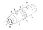
2 ・・・・・・・・・・・・・ ソケット
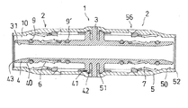
3 ・・・・・・・・・・・・・ 管継手本体
30・・・・・・・・・・・・・ 通路開口部
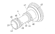
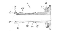
31・・・・・・・・・・・・・ 先端部
4 ・・・・・・・・・・・・・ 内筒体
40・・・・・・・・・・・・・ 外周面
41・・・・・・・・・・・・・ フランジ
42・・・・・・・・・・・・・ 外縁
43・・・・・・・・・・・・・ 先端
44・・・・・・・・・・・・・ 固定壁
45・・・・・・・・・・・・・ テーパー壁
46,46’・・・・・ 溝部
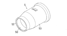
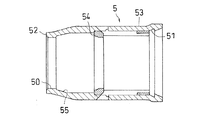
5 ・・・・・・・・・・・・・ 外筒体
50・・・・・・・・・・・・・ 内周面
51・・・・・・・・・・・・・ 連結溝
52・・・・・・・・・・・・・ 先端
53・・・・・・・・・・・・・ 外周面
54・・・・・・・・・・・・・ 固定壁
55・・・・・・・・・・・・・ テーパー壁
56・・・・・・・・・・・・・ 挿入確認口
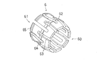
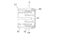
6 ・・・・・・・・・・・・・ 内側ロックリング
60・・・・・・・・・・・・・ 固定端
61・・・・・・・・・・・・・ 自由端
62・・・・・・・・・・・・・ 膨らみ部
63・・・・・・・・・・・・・ スリット
64・・・・・・・・・・・・・ 第1の外向き爪部
65・・・・・・・・・・・・・ 第2の外向き爪部
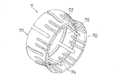
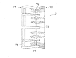
7 ・・・・・・・・・・・・・ 外側ロックリング
70・・・・・・・・・・・・・ 固定端
71・・・・・・・・・・・・・ 自由端
72・・・・・・・・・・・・・ くびれ部
73・・・・・・・・・・・・・ スリット
74・・・・・・・・・・・・・ 第1の内向き爪部
75・・・・・・・・・・・・・ 第2の内向き爪部
8 ・・・・・・・・・・・・・ 接続管
80・・・・・・・・・・・・・ 内周面
81・・・・・・・・・・・・・ 外周面
9,9’・・・・・・・・・ シールリング
10・・・・・・・・・・・・・ 収容部
11・・・・・・・・・・・・・ 挿入口
100・・・・・・・・・・・ 挿入確認手段
101・・・・・・・・・・・ 棒状部材
102・・・・・・・・・・・ リング部品
Claims (10)
- 継手本体と、
径方向に平行な固定壁と、軸方向外部側へ向けて連続的に拡径するテーパー壁とを外周面に有し、そして前記継手本体から軸方向外部側へ向けて延びた内筒体と、
前記内筒体の外側へ配置され、前記内筒体との間に接続管を受け入れるための収容部を形成する外筒体と、そして
片持ちの自由端を形成するための複数のスリットを有する筒状体であって、前記接続管挿入時、前記筒状体の弾性変形により前記接続管の内周面を押圧する第1の外向き爪部と、前記自由端に配置されており、前記接続管引き抜き時、前記接続管を係止する第2の外向き爪部とを有し、そして前記内筒体の固定壁とテーパー壁との間で軸方向に移動可能に配置されている内側ロックリングを備えた管継手において、
前記接続管を前記収容部の所定の位置まで挿入後、引き抜き方向へ移動する時、前記内側ロックリングは、前記第1の外向き爪部が前記接続管の内周面に係止することにより前記接続管と共に引き抜き方向へ移動され、そして前記内側ロックリングの自由端は前記内筒体のテーパー壁領域へ進入し、前記テーパー壁との相互作用により前記第2の外向き爪部を前記接続管の内周面へ押し付けるように拡径されることを特徴とする管継手。 - 継手本体と、
前記継手本体から軸方向外部側へ向けて延びた内筒体と、
径方向に平行な固定壁と、軸方向外部側へ向けて連続的に縮径するテーパー壁とを内周面に有し、そして前記内筒体の外側へ配置され、前記内筒体との間に接続管を受け入れるための収容部を形成する外筒体と、そして
片持ちの自由端を形成するための複数のスリットを有する筒状体であって、前記接続管挿入時、前記筒状体の弾性変形により前記接続管の外周面を押圧する第1の内向き爪部と、前記自由端に配置されており、前記接続管引き抜き時、前記接続管を係止する第2の内向き爪部とを有し、そして前記外筒体の固定壁とテーパー壁との間で軸方向に移動可能に配置されている外側ロックリングを備えた管継手において、
前記接続管を前記収容部の所定の位置まで挿入後、引き抜き方向へ移動する時、前記外側ロックリングは、前記第1の内向き爪部が前記接続管の外周面に係止することにより前記接続管と共に引き抜き方向へ移動され、そして前記外側ロックリングの自由端は前記外筒体のテーパー壁領域へ進入し、前記テーパー壁との相互作用により前記第2の内向き爪部を前記接続管の外周面へ押し付けるように縮径されることを特徴とする管継手。 - 継手本体と、
径方向に平行な固定壁と、軸方向外部側へ向けて連続的に拡径するテーパー壁とを外周面に有し、そして前記継手本体から軸方向外部側へ向けて延びた内筒体と、
径方向に平行な固定壁と、軸方向外部側へ向けて連続的に縮径するテーパー壁とを内周面に有し、そして前記内筒体の外側へ配置され、前記内筒体との間に接続管を受け入れるための収容部を形成する外筒体と、
片持ちの自由端を形成するための複数のスリットを有する筒状体であって、前記接続管挿入時、前記筒状体の弾性変形により前記接続管の内周面を押圧する第1の外向き爪部と、前記自由端に配置されており、前記接続管引き抜き時、前記接続管を係止する第2の外向き爪部とを有し、そして前記内筒体の固定壁とテーパー壁との間で軸方向に移動可能に配置されている内側ロックリングと、そして
片持ちの自由端を形成するための複数のスリットを有する筒状体であって、前記接続管挿入時、前記筒状体の弾性変形により前記接続管の外周面を押圧する第1の内向き爪部と、前記自由端に配置されており、前記接続管引き抜き時、前記接続管を係止する第2の内向き爪部とを有し、そして前記外筒体の固定壁とテーパー壁との間で軸方向に移動可能に配置されている外側ロックリングを備えた管継手において、
前記接続管を前記収容部の所定の位置まで挿入後、引き抜き方向へ移動する時、前記内側ロックリングは、前記第1の外向き爪部が前記接続管の内周面に係止することにより前記接続管と共に引き抜き方向へ移動され、そして前記内側ロックリングの自由端は前記内筒体のテーパー壁領域へ進入し、前記テーパー壁との相互作用により前記第2の外向き爪部を前記接続管の内周面へ押し付けるように拡径され、かつ前記外側ロックリングは、前記第1の内向き爪部が前記接続管の外周面に係止することにより前記接続管と共に引き抜き方向へ移動され、そして前記外側ロックリングの自由端は前記外筒体のテーパー壁領域へ進入し、前記テーパー壁との相互作用により前記第2の内向き爪部を前記接続管の外周面へ押し付けるように縮径されることを特徴とする管継手。 - 前記内側ロックリングは、その胴部に径方向外側へ向けて湾曲した膨らみ部を有しており、及び/又は前記外側ロックリングは、その胴部に径方向内側へ向けて湾曲したくびれ部を有していることを特徴とする請求項1ないし3のいずれかに記載の管継手。
- 前記第1の外向き爪部は、前記第2の外向き爪部より軸方向内部側へ配置されており、及び/又は前記第1の内向き爪部は、前記第2の内向き爪部より軸方向内部側へ配置されていることを特徴とする請求項1ないし3のいずれかに記載の管継手。
- 前記第1の外向き爪部は、軸方向において前記第1の内向き爪部と異なる位置に配置されており、及び/又は前記第2の外向き爪部は、軸方向において前記第2の内向き爪部と異なる位置に配置されていることを特徴とする請求項3に記載の管継手。
- 前記内筒体の外周面及び/又は前記外筒体の内周面は、前記接続管との間隙をシールするために、少なくとも1つのシールリングを前記第2の内向き爪部及び/又は前記第2の外向き爪部と対抗する位置に備えていることを特徴とする請求項1ないし3のいずれかに記載の管継手。
- 前記内側又は外側ロックリングは、ポリフェニルサルホン(PPSU)樹脂又はポリフェニレンサルファイド(PPS)樹脂のプラスチック材料若しくは金属材料から成形されていることを特徴とする請求項1ないし3のいずれかに記載の管継手。
- 前記外筒体は、前記接続管が前記収容部へ挿入されたことを直接的に又は挿入確認部材を介して間接的に目視により確認するための貫通孔を備えていることを特徴とする請求項1ないし3のいずれかに記載の管継手。
- 前記継手本体および前記内筒体は、一体的に成形されていることを特徴とする請求項1ないし3のいずれかに記載の管継手。
Priority Applications (1)
| Application Number | Priority Date | Filing Date | Title |
|---|---|---|---|
| JP2009242397A JP5334792B2 (ja) | 2009-10-21 | 2009-10-21 | 管継手 |
Applications Claiming Priority (1)
| Application Number | Priority Date | Filing Date | Title |
|---|---|---|---|
| JP2009242397A JP5334792B2 (ja) | 2009-10-21 | 2009-10-21 | 管継手 |
Publications (2)
| Publication Number | Publication Date |
|---|---|
| JP2011089565A JP2011089565A (ja) | 2011-05-06 |
| JP5334792B2 true JP5334792B2 (ja) | 2013-11-06 |
Family
ID=44107997
Family Applications (1)
| Application Number | Title | Priority Date | Filing Date |
|---|---|---|---|
| JP2009242397A Expired - Fee Related JP5334792B2 (ja) | 2009-10-21 | 2009-10-21 | 管継手 |
Country Status (1)
| Country | Link |
|---|---|
| JP (1) | JP5334792B2 (ja) |
Cited By (1)
| Publication number | Priority date | Publication date | Assignee | Title |
|---|---|---|---|---|
| WO2020001029A1 (zh) * | 2018-06-27 | 2020-01-02 | 日丰企业(佛山)有限公司 | 外密封连接管件及管道 |
Families Citing this family (6)
| Publication number | Priority date | Publication date | Assignee | Title |
|---|---|---|---|---|
| AT512772B1 (de) * | 2012-09-10 | 2013-11-15 | Ke Kelit Kunststoffwerk Gmbh | Steckkupplung für ein metallisches Rohr, insbesondere für Wasserleitungen |
| JP2015209911A (ja) * | 2014-04-25 | 2015-11-24 | アロン化成株式会社 | 管継手用アダプター |
| WO2018184371A1 (zh) * | 2017-04-07 | 2018-10-11 | 上海飞斯耐暖通科技有限公司 | 一种新型快速管接头 |
| CN106838517B (zh) * | 2017-04-07 | 2018-09-07 | 上海飞斯耐暖通科技有限公司 | 一种新型快速管接头 |
| CN111365545A (zh) * | 2020-03-31 | 2020-07-03 | 黄晓峰 | 一种柔性管的快插管件 |
| CN115788816B (zh) * | 2022-12-23 | 2024-02-02 | 中山市宝悦嘉电子有限公司 | 一种显影药水添加用自动计量设备 |
Family Cites Families (9)
| Publication number | Priority date | Publication date | Assignee | Title |
|---|---|---|---|---|
| DE3905722A1 (de) * | 1989-01-25 | 1990-07-26 | Festo Kg | Verbindungsvorrichtung |
| JPH1151274A (ja) * | 1997-07-30 | 1999-02-26 | Sekisui Chem Co Ltd | 管継手およびその組立方法 |
| JPH11223288A (ja) * | 1998-02-05 | 1999-08-17 | Bridgestone Flowtech Corp | 管継手の構造 |
| JP2001021087A (ja) * | 1999-07-08 | 2001-01-26 | Sekisui Chem Co Ltd | 管継手 |
| JP4179919B2 (ja) * | 2003-04-28 | 2008-11-12 | 積水化学工業株式会社 | 管継手 |
| JP4391222B2 (ja) * | 2003-12-22 | 2009-12-24 | ブリヂストンフローテック株式会社 | 管継手 |
| JP2006118704A (ja) * | 2004-09-21 | 2006-05-11 | Hitachi Metals Ltd | 差込み型継手 |
| NL1029408C2 (nl) * | 2005-07-01 | 2007-01-04 | Wavin Bv | Buiskoppeling. |
| JP4962849B2 (ja) * | 2006-11-30 | 2012-06-27 | 日立金属株式会社 | 管継手 |
-
2009
- 2009-10-21 JP JP2009242397A patent/JP5334792B2/ja not_active Expired - Fee Related
Cited By (1)
| Publication number | Priority date | Publication date | Assignee | Title |
|---|---|---|---|---|
| WO2020001029A1 (zh) * | 2018-06-27 | 2020-01-02 | 日丰企业(佛山)有限公司 | 外密封连接管件及管道 |
Also Published As
| Publication number | Publication date |
|---|---|
| JP2011089565A (ja) | 2011-05-06 |
Similar Documents
| Publication | Publication Date | Title |
|---|---|---|
| JP5334792B2 (ja) | 管継手 | |
| JP5286129B2 (ja) | 管継手 | |
| EP2503207B1 (en) | Pipe joint | |
| CN102691836B (zh) | 管接头 | |
| JP4174738B2 (ja) | ホース継手 | |
| EP1074781B1 (en) | Pipe joint | |
| IT9067767A1 (it) | Connettore per tubi | |
| JP4906973B1 (ja) | 管継手 | |
| WO2014010235A1 (ja) | コネクタ | |
| EP2508784B1 (en) | Pipe Coupling | |
| JP5486895B2 (ja) | 管継手 | |
| CN102099610A (zh) | 用于压力介质导管的插塞式连接装置 | |
| CN102544883B (zh) | 拉绳脱落连接器 | |
| JPWO2009150739A1 (ja) | 管継手 | |
| KR101681787B1 (ko) | 관이음매 | |
| JPH11201347A (ja) | 管継手 | |
| JP2018115739A (ja) | 管継手 | |
| JP4444878B2 (ja) | 配管継手 | |
| JP2018109422A (ja) | 管継手 | |
| JP6370721B2 (ja) | 連結具及びそれを用いたコンクリート部材の連結装置 | |
| JP2013221586A (ja) | 管継手 | |
| JP4873604B2 (ja) | 管継手 | |
| JPS6110077Y2 (ja) | ||
| JP2002213664A (ja) | 管継手 | |
| JP2006009997A (ja) | 管継手 |
Legal Events
| Date | Code | Title | Description |
|---|---|---|---|
| A621 | Written request for application examination |
Free format text: JAPANESE INTERMEDIATE CODE: A621 Effective date: 20120529 |
|
| A977 | Report on retrieval |
Free format text: JAPANESE INTERMEDIATE CODE: A971007 Effective date: 20130711 |
|
| TRDD | Decision of grant or rejection written | ||
| A01 | Written decision to grant a patent or to grant a registration (utility model) |
Free format text: JAPANESE INTERMEDIATE CODE: A01 Effective date: 20130723 |
|
| A61 | First payment of annual fees (during grant procedure) |
Free format text: JAPANESE INTERMEDIATE CODE: A61 Effective date: 20130730 |
|
| R150 | Certificate of patent or registration of utility model |
Ref document number: 5334792 Country of ref document: JP Free format text: JAPANESE INTERMEDIATE CODE: R150 Free format text: JAPANESE INTERMEDIATE CODE: R150 |
|
| R250 | Receipt of annual fees |
Free format text: JAPANESE INTERMEDIATE CODE: R250 |
|
| R250 | Receipt of annual fees |
Free format text: JAPANESE INTERMEDIATE CODE: R250 |
|
| R250 | Receipt of annual fees |
Free format text: JAPANESE INTERMEDIATE CODE: R250 |
|
| R250 | Receipt of annual fees |
Free format text: JAPANESE INTERMEDIATE CODE: R250 |
|
| R250 | Receipt of annual fees |
Free format text: JAPANESE INTERMEDIATE CODE: R250 |
|
| LAPS | Cancellation because of no payment of annual fees |