JP5334792B2 - Pipe fitting - Google Patents
Pipe fitting Download PDFInfo
- Publication number
- JP5334792B2 JP5334792B2 JP2009242397A JP2009242397A JP5334792B2 JP 5334792 B2 JP5334792 B2 JP 5334792B2 JP 2009242397 A JP2009242397 A JP 2009242397A JP 2009242397 A JP2009242397 A JP 2009242397A JP 5334792 B2 JP5334792 B2 JP 5334792B2
- Authority
- JP
- Japan
- Prior art keywords
- pipe
- lock ring
- claw portion
- peripheral surface
- connecting pipe
- Prior art date
- Legal status (The legal status is an assumption and is not a legal conclusion. Google has not performed a legal analysis and makes no representation as to the accuracy of the status listed.)
- Expired - Fee Related
Links
Images
Classifications
-
- F—MECHANICAL ENGINEERING; LIGHTING; HEATING; WEAPONS; BLASTING
- F16—ENGINEERING ELEMENTS AND UNITS; GENERAL MEASURES FOR PRODUCING AND MAINTAINING EFFECTIVE FUNCTIONING OF MACHINES OR INSTALLATIONS; THERMAL INSULATION IN GENERAL
- F16L—PIPES; JOINTS OR FITTINGS FOR PIPES; SUPPORTS FOR PIPES, CABLES OR PROTECTIVE TUBING; MEANS FOR THERMAL INSULATION IN GENERAL
- F16L37/00—Couplings of the quick-acting type
- F16L37/08—Couplings of the quick-acting type in which the connection between abutting or axially overlapping ends is maintained by locking members
- F16L37/084—Couplings of the quick-acting type in which the connection between abutting or axially overlapping ends is maintained by locking members combined with automatic locking
- F16L37/092—Couplings of the quick-acting type in which the connection between abutting or axially overlapping ends is maintained by locking members combined with automatic locking by means of elements wedged between the pipe and the frusto-conical surface of the body of the connector
- F16L37/0925—Couplings of the quick-acting type in which the connection between abutting or axially overlapping ends is maintained by locking members combined with automatic locking by means of elements wedged between the pipe and the frusto-conical surface of the body of the connector with rings which bite into the wall of the pipe
-
- F—MECHANICAL ENGINEERING; LIGHTING; HEATING; WEAPONS; BLASTING
- F16—ENGINEERING ELEMENTS AND UNITS; GENERAL MEASURES FOR PRODUCING AND MAINTAINING EFFECTIVE FUNCTIONING OF MACHINES OR INSTALLATIONS; THERMAL INSULATION IN GENERAL
- F16L—PIPES; JOINTS OR FITTINGS FOR PIPES; SUPPORTS FOR PIPES, CABLES OR PROTECTIVE TUBING; MEANS FOR THERMAL INSULATION IN GENERAL
- F16L37/00—Couplings of the quick-acting type
- F16L37/08—Couplings of the quick-acting type in which the connection between abutting or axially overlapping ends is maintained by locking members
- F16L37/084—Couplings of the quick-acting type in which the connection between abutting or axially overlapping ends is maintained by locking members combined with automatic locking
- F16L37/092—Couplings of the quick-acting type in which the connection between abutting or axially overlapping ends is maintained by locking members combined with automatic locking by means of elements wedged between the pipe and the frusto-conical surface of the body of the connector
- F16L37/0926—Couplings of the quick-acting type in which the connection between abutting or axially overlapping ends is maintained by locking members combined with automatic locking by means of elements wedged between the pipe and the frusto-conical surface of the body of the connector with an inner support sleeve arranged within the pipe
-
- F—MECHANICAL ENGINEERING; LIGHTING; HEATING; WEAPONS; BLASTING
- F16—ENGINEERING ELEMENTS AND UNITS; GENERAL MEASURES FOR PRODUCING AND MAINTAINING EFFECTIVE FUNCTIONING OF MACHINES OR INSTALLATIONS; THERMAL INSULATION IN GENERAL
- F16L—PIPES; JOINTS OR FITTINGS FOR PIPES; SUPPORTS FOR PIPES, CABLES OR PROTECTIVE TUBING; MEANS FOR THERMAL INSULATION IN GENERAL
- F16L2201/00—Special arrangements for pipe couplings
- F16L2201/10—Indicators for correct coupling
Landscapes
- Engineering & Computer Science (AREA)
- General Engineering & Computer Science (AREA)
- Mechanical Engineering (AREA)
- Joints With Sleeves (AREA)
- Quick-Acting Or Multi-Walled Pipe Joints (AREA)
- Joints With Pressure Members (AREA)
Abstract
Description
本発明は、ワンタッチで接続管を接続する管継手に関し、特に管継手の接続管収容部の中に、接続管挿入時、その周面を押圧する第1の爪部と、接続管引き抜き時、接続管を係止するために機能する第2の爪部とを有するロックリングを備えることにより、接続管を挿入後、引き抜き方向へ移動する時、第1の爪部は接続管に係止され、第2の爪部は周囲のテーパー壁との相互作用により、接続管の周面を押し付けるように変位することを特徴とする管継手に関する。 The present invention relates to a pipe joint for connecting a connection pipe with a single touch, and in particular, in the connection pipe housing part of the pipe joint, when inserting the connection pipe, when the connection pipe is pulled, By providing a lock ring having a second claw portion that functions to lock the connecting pipe, the first claw portion is locked to the connecting pipe when the connecting pipe is inserted and then moved in the pulling direction. The second claw portion relates to a pipe joint that is displaced so as to press the peripheral surface of the connecting pipe by interaction with a surrounding tapered wall.
従来より、ワンタッチで接続管を接続するための管継手が知られている。例えば、実開平4−18793号公報(特許文献1)、特開2001−193883号公報(特許文献2)、特開2003−227592号公報(特許文献3)には、同心に配置された内側筒体と挿入口へ向けて縮径するテーパー面を備えた外側筒体との間に、接続管を係止するための歯または爪などの突起物を有する筒状のロックリングが軸方向に移動可能に内蔵されていることを基本構成とするワンタッチ式の管継手が開示されている。このタイプの管継手は、接続管を最深部まで挿入した後、引き戻すことにより、ロックリングを挿入口付近へ移動させ、そしてロックリングの突起部を外側筒体の挿入口付近に形成されたテーパー面との相互作用により、接続管の外周面に食い込ませるように縮径させることにより接続管の抜けを防止するというものである。 Conventionally, a pipe joint for connecting a connecting pipe with one touch is known. For example, Japanese Utility Model Laid-Open No. 4-18793 (Patent Document 1), Japanese Patent Application Laid-Open No. 2001-193883 (Patent Document 2), and Japanese Patent Application Laid-Open No. 2003-227592 (Patent Document 3) disclose concentric inner cylinders. A cylindrical lock ring with protrusions such as teeth or claws for locking the connecting pipe moves in the axial direction between the body and the outer cylinder with a tapered surface that decreases in diameter toward the insertion port There is disclosed a one-touch type pipe joint whose basic configuration is to be built in. This type of pipe joint is a taper formed by inserting the connecting pipe to the deepest part and then pulling it back to move the lock ring to the vicinity of the insertion port, and the protrusion of the lock ring is formed near the insertion port of the outer cylinder. The diameter of the connecting pipe is reduced by the interaction with the surface so as to bite into the outer peripheral surface of the connecting pipe, thereby preventing the connecting pipe from coming off.
また、このタイプの管継手は、接続管挿入後、ロックリングが何らかの原因で挿入口内部へ移動し、そして歯または爪の食い込みが解除されることによる抜けを防止する必要があるため、通常ロックリングの後方には、常にロックリングを挿入口へ向けて付勢するバネなどの弾性体が配置されているという特徴がある。 In addition, this type of fittings is normally locked because it is necessary to prevent the lock ring from moving into the insertion slot for some reason after insertion of the connecting pipe and releasing the biting of teeth or claws. There is a feature that an elastic body such as a spring that constantly urges the lock ring toward the insertion port is arranged behind the ring.
特開2005−172218号公報(特許文献4)には、上記特許文献1−3に記載された管継手と略同じ構成を有するものであるが、管継手の内部に挿入された接続管を内側から支持する内側筒体を具備していないタイプのワンタッチ式の管継手が開示されている。 Japanese Patent Application Laid-Open No. 2005-172218 (Patent Document 4) has substantially the same configuration as the pipe joint described in Patent Document 1-3, but the inside of the connection pipe inserted into the pipe joint is the inside. A one-touch type pipe joint that does not include an inner cylindrical body that is supported from the above is disclosed.
WO2006/135227号公報(特許文献5)には、上記特許文献1−3に記載された管継手の他の変形例であって、外側スリーブおよび内側スリーブは共に挿入口の間隙を狭める向きのテーパー面を有しており、そしてそれらの間には接続管を受け入れることができるように、歯を有する同心に配置された外側グリップリングおよび内側グリップリングと、そして両グリップリングを最深部で連結する底部とからなる筒状のロックリングが軸方向に移動可能に配置されていることを基本構成とするワンタッチ式の管継手が記載されている。 WO 2006/135227 (Patent Document 5) is another modification of the pipe joint described in Patent Document 1-3, and both the outer sleeve and the inner sleeve are tapered to narrow the gap of the insertion port. And concentrically arranged outer and inner grip rings with teeth, and both grip rings connected at their deepest depth so that they can receive a connecting tube between them. There is described a one-touch type pipe joint having a basic configuration in which a cylindrical lock ring including a bottom portion is arranged to be movable in an axial direction.
したがって、特許文献5に記載の管継手の場合も、接続管の固定はロックリングを介して接続管を外側筒体と内側筒体との間隙の最深部まで挿入した後、引き戻すことにより、ロックリングを挿入口付近へ移動させ、そしてロックリングの歯を、外側筒体および内側筒体の挿入口付近に形成されたテーパー面との相互作用により接続管の抜けを防止するようにその内外周面に食い込ませることにより達成される。
Therefore, also in the case of the pipe joint described in
そして、このタイプの管継手においてもロックリングが挿入口内部へ移動することによる接続管の抜けを防止する必要があるため、ロックリングの底部後方には、常にロックリングを挿入口へ向けて付勢するためのバネリップが一体成形されている。 And even in this type of pipe joint, it is necessary to prevent the connecting pipe from coming off due to the lock ring moving into the insertion port. Therefore, always attach the lock ring toward the insertion port at the rear of the bottom of the lock ring. A spring lip for biasing is integrally formed.
しかしながら、特許文献1−5に記載されるような軸方向に移動可能な筒状のロックリングと継手本体のテーパー面との相互作用を利用したタイプのワンタッチ式の管継手の場合、以下のような問題点があった。 However, in the case of a one-touch type pipe joint using the interaction between the axially movable cylindrical lock ring and the tapered surface of the joint body as described in Patent Documents 1-5, There was a serious problem.
すなわち、移動式のロックリングを有するタイプのワンタッチ式の管継手では、接続管挿入後、ロックリングの移動による接続管の抜けを防止するため、ロックリングをバネなどにより常に挿入口へ向けて付勢しなければならない。したがって、接続管挿入前の自由状態では、ロックリングの端部は外側筒体若しくは内側筒体に設けられたテーパー面へ進入し、接続管挿入口の間隙を狭めるように縮径または拡径されている。このため、接続管を挿入する際のロックリングの歯または爪による挿入抵抗が大きく、挿入後の接続管の外周面若しくは内周面も深く傷付けられるため、シールリングによるシール効果やロックリングによる係止力を十分に得られないという問題があった。 In other words, in a one-touch type fitting with a movable lock ring, the lock ring is always attached to the insertion port with a spring or the like to prevent the connection pipe from coming off due to the movement of the lock ring after the connection pipe is inserted. You have to be strong. Therefore, in the free state before the connection pipe is inserted, the end of the lock ring enters the outer cylinder or the tapered surface provided on the inner cylinder, and is reduced or enlarged so as to narrow the gap of the connection pipe insertion port. ing. For this reason, the insertion resistance due to the teeth or claws of the lock ring when inserting the connection pipe is large, and the outer peripheral surface or inner peripheral surface of the connection pipe after insertion is deeply damaged. There was a problem that sufficient stopping power could not be obtained.
また、出願人は、上記移動式のロックリングを有するタイプのワンタッチ式の管継手の問題を解決するため、管継手の収容部の中に、径方向へ向けて押圧されると軸方向へ伸長するように変形する湾曲したロックリングを設けることにより、接続管挿入時、ロックリングの爪部を有する自由端が周囲のテーパー壁との相互作用により、接続管の周面を押し付けるように変位することを特徴とする管継手を開発し、特願2009−078716号として特許出願をした(特許文献6)。しかしながら、前記湾曲したロックリングを備えるワンタッチ式の管継手においても、接続管を挿入する際のロックリングの爪部による挿入抵抗を十分に小さくすることができないという問題があった。 Further, in order to solve the problem of the one-touch type pipe joint having the movable lock ring, the applicant extends in the axial direction when the pipe joint is pressed in the radial direction. By providing a curved lock ring that deforms in such a way, when the connecting pipe is inserted, the free end having the claw portion of the lock ring is displaced so as to press the peripheral surface of the connecting pipe by interaction with the surrounding tapered wall. A pipe joint characterized by this was developed, and a patent application was filed as Japanese Patent Application No. 2009-078716 (Patent Document 6). However, even in the one-touch type pipe joint provided with the curved lock ring, there is a problem that the insertion resistance due to the claw portion of the lock ring when inserting the connection pipe cannot be sufficiently reduced.
さらに、管継手の内部に軸方向に移動可能なロックリングを有するタイプ以外のワンタッチ式の管継手としては、特開平9−236190号公報(特許文献7)、特開2006−118704号公報(特許文献8)、特開2008−164074号公報(特許文献9)に記載されているような、接続管を受け入れるための収容部を形成するために同心に配置された外側筒体と継手本体から延びた内側筒体とからなり、内側筒体の外周面には、接続管の内周面に食い込ませることにより抜けを防止する複数の放射状に伸びた歯または爪を有する環状のロックリングが固定されているタイプのワンタッチ式の管継手が知られている。 Further, as one-touch type pipe joints other than the type having a lock ring movable in the axial direction inside the pipe joint, Japanese Patent Laid-Open No. 9-236190 (Patent Document 7) and Japanese Patent Laid-Open No. 2006-118704 (Patent) Document 8), extending from an outer cylinder and a joint body arranged concentrically to form a receiving part for receiving a connecting pipe as described in JP 2008-164074 (Patent Document 9). An annular lock ring having a plurality of radially extending teeth or pawls is secured to the outer peripheral surface of the inner cylindrical body. One-touch type pipe joints are known.
また、特開2002−106772号公報(特許文献10)、特開2003−307290号公報(特許文献11)に記載されているように、基本的に上記特許文献7−8に記載された管継手と同じ構造を有するものであるが、複数の歯または爪を有する環状のロックリングが内側筒体の外周面からではなく、外側筒体の内周面から接続管の外周面に食い込ませるように固定されているタイプのワンタッチ式の管継手も知られている。 Further, as described in Japanese Patent Application Laid-Open No. 2002-106762 (Patent Document 10) and Japanese Patent Application Laid-Open No. 2003-307290 (Patent Document 11), the pipe joint basically described in Patent Document 7-8 is basically described. The ring-shaped lock ring having a plurality of teeth or claws is inserted from the inner peripheral surface of the outer cylindrical body into the outer peripheral surface of the connecting pipe instead of from the outer peripheral surface of the inner cylindrical body. A fixed type one-touch type pipe joint is also known.
しかしながら、特許文献7−11に記載されているような環状のロックリングが内部に固定されているようなタイプのワンタッチ式の管継手の場合、ロックリングの歯または爪は、挿入される接続管の表面に対し十分に食い込ませる必要があるために内側筒体または外側筒体の表面から大きく突出させて配置しなければならない。このため、接続管を挿入する際の抵抗、及びその内周面または外周面が受ける損傷は、通常、前述のテーパー面との相互作用を利用した移動式のロックリングを有するタイプの管継手よりも大きくなり、その結果、シールリングによる十分なシール効果を得られず、また、この問題を解消するためにシールリングを環状のロックリングの後方に取り付けなければならないなど設計上多くの制約が生じるといった問題があった。 However, in the case of a one-touch type pipe joint in which an annular lock ring is fixed inside as described in Patent Document 7-11, the teeth or claws of the lock ring are inserted into the connecting pipe to be inserted. Therefore, it is necessary to sufficiently protrude from the surface of the inner cylinder body or the outer cylinder body. For this reason, resistance at the time of inserting a connecting pipe and damage to the inner or outer peripheral surface thereof are usually higher than those of a pipe joint having a movable lock ring utilizing the interaction with the tapered surface described above. As a result, a sufficient sealing effect due to the seal ring cannot be obtained, and there are many design restrictions such that the seal ring must be mounted behind the annular lock ring to solve this problem. There was a problem.
そこで、本発明は、接続管を接続後、引き抜き方向への力が働く時、接続管を確実かつ強固に係止することができ、それでいて接続管を挿入する際のロックリングの歯または爪による挿入抵抗が小さく、そして挿入後の接続管の外周面若しくは内周面を傷付けることも殆んどない、簡易構造でかつ信頼性の高いワンタッチ式の管継手を提供することを目的とする。 Therefore, the present invention can reliably and firmly lock the connecting pipe when a force in the pulling direction is applied after connecting the connecting pipe, and yet the lock ring teeth or claws are used when the connecting pipe is inserted. An object of the present invention is to provide a one-touch type pipe joint having a simple structure and high reliability, which has a small insertion resistance and hardly damages the outer peripheral surface or inner peripheral surface of the connecting pipe after insertion.
そこで、本発明者等は、管継手本体のテーパー面との相互作用を利用した筒状のロックリングを有するワンタッチ式の管継手について鋭意検討を重ねた結果、1つの筒状のロックリングにおいて、爪部を、接続管挿入後、ロックリングを接続管の動きに追従させるために機能する第1の爪部と、接続管へ引き抜き方向への力が働く時、接続管を強固に係止するために機能する第2の爪部とに分離することにより上記の課題を解決し、本発明を完成させるに至った。 Therefore, as a result of intensive studies on one-touch type pipe joints having a cylindrical lock ring utilizing the interaction with the tapered surface of the pipe joint body, the present inventors, in one cylindrical lock ring, After inserting the connecting tube into the claw portion, the first claw portion that functions to cause the lock ring to follow the movement of the connecting tube and when the force in the pulling direction acts on the connecting tube, the connecting tube is firmly locked. Therefore, the above-mentioned problems have been solved by separating the second claw portion that functions to achieve the present invention.
すなわち、本発明によれば、継手本体と、径方向に平行な固定壁と、軸方向外部側へ向けて連続的に拡径するテーパー壁とを外周面に有し、そして前記継手本体から軸方向外部側へ向けて延びた内筒体と、前記内筒体の外側へ配置され、前記内筒体との間に接続管を受け入れるための収容部を形成する外筒体と、そして片持ちの自由端を形成するための複数のスリットを有する筒状体であって、前記接続管挿入時、前記筒状体の弾性変形により前記接続管の内周面を押圧する第1の外向き爪部と、前記自由端に配置されており、前記接続管引き抜き時、前記接続管を係止する第2の外向き爪部とを有し、そして前記内筒体の固定壁とテーパー壁との間で軸方向に移動可能に配置されている内側ロックリングを備えた管継手において、前記接続管を前記収容部の所定の位置まで挿入後、引き抜き方向へ移動する時、前記内側ロックリングは、前記第1の外向き爪部が前記接続管の内周面に係止することにより前記接続管と共に引き抜き方向へ移動され、そして前記内側ロックリングの自由端は前記内筒体のテーパー壁領域へ進入し、前記テーパー壁との相互作用により前記第2の外向き爪部を前記接続管の内周面へ押し付けるように拡径されることを特徴とする管継手が提供される。 That is, according to the present invention, the outer peripheral surface has a joint body, a fixed wall parallel to the radial direction, and a tapered wall that continuously expands toward the outside in the axial direction, and the shaft extends from the joint body. An inner cylinder that extends outward in the direction, an outer cylinder that is disposed outside the inner cylinder and that forms a receiving portion for receiving a connection pipe between the inner cylinder, and a cantilever A first outer claw that has a plurality of slits for forming a free end thereof, and that presses the inner peripheral surface of the connecting pipe by elastic deformation of the cylindrical body when the connecting pipe is inserted. And a second outward claw portion that is disposed at the free end and locks the connection pipe when the connection pipe is pulled out, and a fixed wall and a taper wall of the inner cylinder body In a pipe joint comprising an inner lock ring arranged so as to be axially movable between When the inner lock ring is moved in the pulling direction after being inserted to a predetermined position of the housing portion, the inner lock ring is configured so that the first outward claw portion is locked to the inner peripheral surface of the connection tube. And the free end of the inner lock ring enters the tapered wall region of the inner cylinder, and the second outward claw portion is moved into the inside of the connecting pipe by interaction with the tapered wall. A pipe joint characterized by being expanded in diameter so as to be pressed against a peripheral surface is provided.
また、本発明によれば、継手本体と、前記継手本体から軸方向外部側へ向けて延びた内筒体と、径方向に平行な固定壁と、軸方向外部側へ向けて連続的に縮径するテーパー壁とを内周面に有し、そして前記内筒体の外側へ配置され、前記内筒体との間に接続管を受け入れるための収容部を形成する外筒体と、そして片持ちの自由端を形成するための複数のスリットを有する筒状体であって、前記接続管挿入時、前記筒状体の弾性変形により前記接続管の外周面を押圧する第1の内向き爪部と、前記自由端に配置されており、前記接続管引き抜き時、前記接続管を係止する第2の内向き爪部とを有し、そして前記外筒体の固定壁とテーパー壁との間で軸方向に移動可能に配置されている外側ロックリングを備えた管継手において、前記接続管を前記収容部の所定の位置まで挿入後、引き抜き方向へ移動する時、前記外側ロックリングは、前記第1の内向き爪部が前記接続管の外周面に係止することにより前記接続管と共に引き抜き方向へ移動され、そして前記外側ロックリングの自由端は前記外筒体のテーパー壁領域へ進入し、前記テーパー壁との相互作用により前記第2の内向き爪部を前記接続管の外周面へ押し付けるように縮径されることを特徴とする管継手が提供される。 Further, according to the present invention, the joint main body, the inner cylindrical body extending from the joint main body toward the outside in the axial direction, the fixed wall parallel to the radial direction, and the contraction toward the outside in the axial direction are continuously performed. An outer cylindrical body having a tapered wall on the inner peripheral surface and disposed outside the inner cylindrical body to form a receiving portion for receiving a connecting pipe between the inner cylindrical body and a piece A cylindrical body having a plurality of slits for forming a free end having a first inward claw that presses the outer peripheral surface of the connection pipe by elastic deformation of the cylindrical body when the connection pipe is inserted. And a second inward claw portion that is disposed at the free end and locks the connection pipe when the connection pipe is pulled out, and a fixed wall and a taper wall of the outer cylinder body A pipe joint having an outer lock ring arranged so as to be axially movable between the connecting pipes When the outer lock ring moves in the pull-out direction after being inserted to a predetermined position of the storage portion, the outer lock ring is pulled out together with the connection tube by the first inward claw portion being locked to the outer peripheral surface of the connection tube. And the free end of the outer lock ring enters the tapered wall region of the outer cylinder, and the second inward claw is moved to the outer peripheral surface of the connecting pipe by interaction with the tapered wall. A pipe joint is provided which is reduced in diameter so as to be pressed.
さらに、本発明によれば、継手本体と、径方向に平行な固定壁と、軸方向外部側へ向けて連続的に拡径するテーパー壁とを外周面に有し、そして前記継手本体から軸方向外部側へ向けて延びた内筒体と、径方向に平行な固定壁と、軸方向外部側へ向けて連続的に縮径するテーパー壁とを内周面に有し、そして前記内筒体の外側へ配置され、前記内筒体との間に接続管を受け入れるための収容部を形成する外筒体と、片持ちの自由端を形成するための複数のスリットを有する筒状体であって、前記接続管挿入時、前記筒状体の弾性変形により前記接続管の内周面を押圧する第1の外向き爪部と、前記自由端に配置されており、前記接続管引き抜き時、前記接続管を係止する第2の外向き爪部とを有し、そして前記内筒体の固定壁とテーパー壁との間で軸方向に移動可能に配置されている内側ロックリングと、そして片持ちの自由端を形成するための複数のスリットを有する筒状体であって、前記接続管挿入時、前記筒状体の弾性変形により前記接続管の外周面を押圧する第1の内向き爪部と、前記自由端に配置されており、前記接続管引き抜き時、前記接続管を係止する第2の内向き爪部とを有し、そして前記外筒体の固定壁とテーパー壁との間で軸方向に移動可能に配置されている外側ロックリングを備えた管継手において、前記接続管を前記収容部の所定の位置まで挿入後、引き抜き方向へ移動する時、前記内側ロックリングは、前記第1の外向き爪部が前記接続管の内周面に係止することにより前記接続管と共に引き抜き方向へ移動され、そして前記内側ロックリングの自由端は前記内筒体のテーパー壁領域へ進入し、前記テーパー壁との相互作用により前記第2の外向き爪部を前記接続管の内周面へ押し付けるように拡径され、かつ前記外側ロックリングは、前記第1の内向き爪部が前記接続管の外周面に係止することにより前記接続管と共に引き抜き方向へ移動され、そして前記外側ロックリングの自由端は前記外筒体のテーパー壁領域へ進入し、前記テーパー壁との相互作用により前記第2の内向き爪部を前記接続管の外周面へ押し付けるように縮径されることを特徴とする管継手が提供される。 Further, according to the present invention, the outer peripheral surface has a joint body, a fixed wall parallel to the radial direction, and a tapered wall that continuously expands toward the outside in the axial direction, and the shaft extends from the joint body. An inner cylinder extending outward in the direction, a fixed wall parallel to the radial direction, and a tapered wall continuously reducing in diameter toward the outer side in the axial direction, and the inner cylinder A cylindrical body that is arranged outside the body and has an outer cylindrical body that forms a receiving portion for receiving a connecting pipe between the inner cylindrical body and a plurality of slits for forming a cantilevered free end. A first outward claw portion that presses an inner peripheral surface of the connection pipe by elastic deformation of the cylindrical body when the connection pipe is inserted, and the free end, and when the connection pipe is pulled out. A second outward claw portion for locking the connecting pipe, and a fixed wall and a tapered wall of the inner cylinder body, A cylindrical body having an inner lock ring arranged so as to be movable in the axial direction, and a plurality of slits for forming a cantilevered free end when the connecting pipe is inserted A first inward claw portion that presses the outer peripheral surface of the connection pipe by elastic deformation of the connection pipe, and a second inward claw that is disposed at the free end and that locks the connection pipe when the connection pipe is pulled out And a pipe joint including an outer lock ring that is arranged so as to be movable in the axial direction between the fixed wall and the tapered wall of the outer cylindrical body. When the inner lock ring moves in the pull-out direction after being inserted to the position, the inner lock ring is moved in the pull-out direction together with the connection pipe by the first outward claw portion engaging with the inner peripheral surface of the connection pipe. , And the free end of the inner lock ring The diameter of the inner cylinder is increased so as to press the second outward claw portion against the inner peripheral surface of the connecting pipe by the interaction with the tapered wall, and the outer lock ring is The first inward claw portion engages with the outer peripheral surface of the connection pipe and is moved in the pulling direction together with the connection pipe, and the free end of the outer lock ring is moved to the tapered wall region of the outer cylinder. A pipe joint is provided which is reduced in diameter so as to enter and to press the second inward claw portion against the outer peripheral surface of the connection pipe by interaction with the tapered wall.
本発明によれば、管継手本体、内筒体および外筒体はいずれも筒形の形状を有しており、このうち管継手本体は内筒体を含み一体的に成形されていてもよい。また、管継手本体および内筒体はその内部に流体を流すための通路開口部を有しており、その先端部は流体の抵抗を少なくするためにファンネル形状とすることが好ましい。さらに、管継手の生産性やコスト面などを重視する場合は、管継手本体、内筒体および外筒体のすべての部品を一体的に成形することもできる。 According to the present invention, the pipe joint body, the inner cylinder body, and the outer cylinder body all have a cylindrical shape, and among these, the pipe joint body includes the inner cylinder body and may be integrally formed. . Moreover, it is preferable that the pipe joint main body and the inner cylindrical body have a passage opening for allowing fluid to flow therein, and that the tip end thereof has a funnel shape in order to reduce the resistance of the fluid. Furthermore, when importance is attached to the productivity and cost of the pipe joint, all parts of the pipe joint main body, the inner cylinder body, and the outer cylinder body can be integrally formed.
管継手の外筒体が継手本体から分離しているタイプの場合、外筒体は継手本体へ回転不能に無理嵌めすることもでき、また、周方向に回転自在に遊嵌することもできる。外筒体を継手本体に対し回転自在に取付けた場合、接続時若しくは接続後に接続管が受ける曲げ応力や回転モーメントを容易に逃がすことができるため、破壊応力に対し比較的柔軟に対応可能な管継手を提供することができる。 In the case of the type in which the outer cylinder of the pipe joint is separated from the joint body, the outer cylinder can be forcibly fitted to the joint body so as not to rotate, or can be loosely fitted in the circumferential direction. When the outer cylinder is attached to the joint body so that it can rotate freely, the bending stress and rotational moment that the connecting pipe receives during or after connection can be easily released, so that the pipe can handle the breaking stress relatively flexibly. A joint can be provided.
また、外筒体の先端は、軸方向において内筒体の先端より外部側へ突出させるのが好ましい。落下などによる外部衝撃から内筒体を保護すると共に、万が一の場合、その破損の範囲を外筒体に止め交換を容易にするためである。 Moreover, it is preferable to make the front-end | tip of an outer cylinder protrude outside from the front-end | tip of an inner cylinder in an axial direction. This is to protect the inner cylinder from an external impact caused by dropping or the like, and in the event of an emergency, the damage range is fixed to the outer cylinder to facilitate replacement.
本発明において継手本体、内筒体及び/又は外筒体の材料は比較的硬質なものであれば特に限定されるものではないが、プラスチック材料または金属材料から成形されていることが好ましい。特にプラスチック材料を使用する場合は、ポリフェニルサルホン(PPSU)樹脂またはポリフェニレンサルファイド(PPS)樹脂であることがより好ましい。 In the present invention, the material of the joint body, the inner cylinder and / or the outer cylinder is not particularly limited as long as it is relatively hard, but is preferably molded from a plastic material or a metal material. In particular, when a plastic material is used, a polyphenylsulfone (PPSU) resin or a polyphenylene sulfide (PPS) resin is more preferable.
本発明によれば、内筒体を含む継手本体および外筒体は同心上に配置されており、そして内筒体と外筒体との間には接続管を受け入れるための収容部が形成されている。そして、管継手の収容部の中には、接続管挿入時、その周面を押圧する第1の爪部と、接続管引き抜き時、接続管を係止するために機能する第2の爪部とを有するロックリングが軸方向に移動可能に配置される。また、このロックリングは、内筒体の外周面または外筒体の内周面のいずれか一方に装着されていればよいが、管継手の落下、溶剤の付着、踏み付けなどにより片方のロックリングが破損した場合でも接続管を確実に把持できるように、その両方に配置されていることが好ましい。 According to the present invention, the joint main body and the outer cylinder including the inner cylinder are arranged concentrically, and a receiving portion for receiving the connection pipe is formed between the inner cylinder and the outer cylinder. ing. And in the accommodating part of a pipe joint, the 1st nail | claw part which presses the surrounding surface at the time of connecting pipe insertion, and the 2nd nail | claw part which functions in order to latch a connecting pipe at the time of pulling out a connecting pipe A lock ring having the following is arranged to be movable in the axial direction. The lock ring may be attached to either the outer peripheral surface of the inner cylindrical body or the inner peripheral surface of the outer cylindrical body. It is preferable that the connecting pipes are arranged on both sides so that the connecting pipe can be securely gripped even if the pipe is damaged.
内筒体の外周面には、内側ロックリングを軸方向に移動可能に配置するため、径方向に平行な固定壁と軸方向外部側へ向けて連続的に拡径しているテーパー壁とが形成される。また、外筒体の内周面には、外側ロックリングを軸方向に移動可能に配置するため、径方向に平行な固定壁と軸方向外部側へ向けて連続的に縮径しているテーパー壁とが形成される。そして、内側ロックリング及び/又は外側ロックリングは、固定壁とテーパー壁との間に配置されることにより、内筒体の外周面及び/又は外筒体の内周面の固定壁との関係で軸方向への移動が実質的に制限される固定端と、テーパー壁との関係で軸方向への移動が許容される自由端とが形成される。したがって、内側ロックリング及び/又は外側ロックリングの固定端は自由端より軸方向内側へ配置されており、自由端には引き抜き時、接続管を係止するための第2の爪部が配設される。 On the outer peripheral surface of the inner cylinder, in order to displace the inner lock ring so as to be movable in the axial direction, there are a fixed wall parallel to the radial direction and a tapered wall continuously expanding toward the outer side in the axial direction. It is formed. Further, on the inner peripheral surface of the outer cylindrical body, an outer lock ring is disposed so as to be movable in the axial direction, so that a fixed wall parallel to the radial direction and a taper continuously reduced in diameter toward the outer side in the axial direction. A wall is formed. The inner lock ring and / or the outer lock ring are arranged between the fixed wall and the taper wall, so that the relationship between the outer peripheral surface of the inner cylindrical body and / or the fixed wall of the inner peripheral surface of the outer cylindrical body is achieved. Thus, a fixed end in which movement in the axial direction is substantially restricted and a free end in which movement in the axial direction is allowed in relation to the tapered wall are formed. Therefore, the fixed end of the inner lock ring and / or the outer lock ring is arranged inward in the axial direction from the free end, and a second claw portion is provided at the free end to lock the connection pipe when pulled out. Is done.
内筒体の外周面に配置される内側ロックリングは、片持ちの自由端を形成するために端部より複数のスリットが切られた筒状体であって、接続管挿入時、弾性変形により接続管の内周面を押圧する第1の外向き爪部と、上記自由端に配置されており、接続管引き抜き時、接続管を係止するために機能する第2の外向き爪部とを有している。 The inner lock ring arranged on the outer peripheral surface of the inner cylinder is a cylindrical body in which a plurality of slits are cut from the end portion to form a cantilever free end. A first outward claw portion that presses the inner peripheral surface of the connection pipe; and a second outward claw portion that is disposed at the free end and functions to lock the connection pipe when the connection pipe is pulled out. have.
第1の外向き爪部の押圧機構は、内側ロックリングの爪部を支持する部分にゴムなどの弾性体を使用することにより達成することができ、若しくは爪部を支持する内側ロックリング自体が弾性変形する構造とすることによっても達成することができる。特に後者の場合、内側ロックリングの胴部には複数のスリットが設けられているため、前記胴部を径方向外側へ向けて膨らむように湾曲する構造とすることが有効である。 The pressing mechanism of the first outward claw portion can be achieved by using an elastic body such as rubber for the portion that supports the claw portion of the inner lock ring, or the inner lock ring itself that supports the claw portion is This can also be achieved by providing a structure that is elastically deformed. Particularly in the latter case, since the body portion of the inner lock ring is provided with a plurality of slits, it is effective to have a structure in which the body portion is curved so as to expand outward in the radial direction.
すなわち、内側ロックリングの膨らみ部はその断面形状においていわゆる尺取虫のような形状を有しているため、径方向内側へ向けて押圧されると撓み、その反力で挿入された接続管の内周面を適度に押圧する。また、スリットは、内側ロックリングの胴部を貫通するように軸方向に延びているため、スリットにより分割された膨らみ部が互いに干渉するのを防止しながら弾性変形するのを容易化する。また、第1の外向き爪部は、第2の外向き爪部より軸方向内部側へ配置されているという特徴も有する。 That is, since the bulging portion of the inner lock ring has a shape like a so-called worm in its cross-sectional shape, it is bent when pressed inward in the radial direction, and the inner circumference of the connecting pipe inserted by the reaction force Press the surface moderately. Further, since the slit extends in the axial direction so as to penetrate the body portion of the inner lock ring, it facilitates elastic deformation while preventing the bulge portions divided by the slit from interfering with each other. Further, the first outward claw portion is also characterized in that it is arranged on the axially inner side from the second outward claw portion.
その結果、接続管を管継手の収容部の所定の位置まで挿入した後、引き抜き方向へ移動すると、内側ロックリングも、第1の外向き爪部が接続管の内周面に係止することにより接続管と共に引き抜き方向へ移動する。そして内側ロックリングの自由端は内筒体のテーパー壁領域へ進入し、テーパー壁との相互作用により第2の外向き爪部を接続管の内周面へ押し付けるように拡径する。 As a result, when the connecting pipe is inserted to a predetermined position in the accommodating portion of the pipe joint and then moved in the pulling direction, the inner lock ring also has the first outward claw portion locked to the inner peripheral surface of the connecting pipe. To move in the pulling direction together with the connecting pipe. Then, the free end of the inner lock ring enters the tapered wall region of the inner cylinder, and the diameter is expanded so as to press the second outward claw portion against the inner peripheral surface of the connecting pipe by interaction with the tapered wall.
このように本発明の管継手では、第1の外向き爪部は挿入された接続管の内周面を適度に押圧するように内側ロックリングの本体により支持されており、他方の接続管の抜けを防止する第2の外向き爪部は、接続管を挿入後、引き抜き方向へ移動しない時、その内周面と略接触しないように後退して内側ロックリングの自由端により支持されている。そして本発明によれば、接続管を挿入する際、接続管が第1の外向き爪部より受ける挿入抵抗は小さいが、接続管が引き抜き方向へ移動すると、第2の外向き爪部がテーパー壁との相互作用により接続管を確実かつ強固に係止する。 As described above, in the pipe joint of the present invention, the first outward claw portion is supported by the main body of the inner lock ring so as to appropriately press the inner peripheral surface of the inserted connection pipe, and the other connection pipe The second outward claw portion for preventing the withdrawal is supported by the free end of the inner lock ring by retreating so as not to substantially contact the inner peripheral surface when the connecting pipe is inserted and does not move in the pulling direction. . According to the present invention, when the connecting pipe is inserted, the insertion resistance received by the connecting pipe from the first outward claw portion is small, but when the connecting pipe moves in the pulling direction, the second outward claw portion is tapered. The connecting pipe is securely and firmly locked by the interaction with the wall.
また、挿入後の接続管が引き抜き方向へ移動すると、内側ロックリングは、第1の外向き爪部の係止作用により必ず接続管と共に引き抜き方向へ移動するため、本発明の管継手は、従来の移動式のロックリングを備えた管継手のようにロックリングを常に挿入口へ向けて付勢するためのバネなどを設ける必要がないといったメリットもある。 When the connecting pipe after insertion moves in the pulling direction, the inner lock ring always moves in the pulling direction together with the connecting pipe by the locking action of the first outward claw portion. There is also an advantage that it is not necessary to provide a spring or the like for always urging the lock ring toward the insertion port as in the case of a pipe joint having the movable lock ring.
一方、外筒体の内周面に配置される外側ロックリングは、片持ちの自由端を形成するために端部より複数のスリットが切られた筒状体であって、接続管挿入時、弾性変形により接続管の外周面を押圧する第1の内向き爪部と、上記自由端に配置されており、接続管引き抜き時、接続管を係止するために機能する第2の内向き爪部とを有している。 On the other hand, the outer lock ring disposed on the inner peripheral surface of the outer cylindrical body is a cylindrical body in which a plurality of slits are cut from the end portion to form a cantilever free end, and when the connecting pipe is inserted, A first inward claw portion that presses the outer peripheral surface of the connection pipe by elastic deformation, and a second inward claw that is disposed at the free end and functions to lock the connection pipe when the connection pipe is pulled out Part.
第1の内向き爪部の押圧機構は、外側ロックリングの爪部を支持する部分にゴムなどの弾性体を使用することにより達成することができ、若しくは爪部を支持する外側ロックリングの本体自体が弾性変形する構造とすることによっても達成することができる。特に後者の場合、外側ロックリングの胴部には複数のスリットが設けられているため、前記胴部を径方向内側へ向けてくびれるように湾曲する構造とすることが有効である。 The pressing mechanism of the first inward claw portion can be achieved by using an elastic body such as rubber for the portion that supports the claw portion of the outer lock ring, or the main body of the outer lock ring that supports the claw portion. It can also be achieved by making the structure itself elastically deformed. Particularly in the latter case, since the body portion of the outer lock ring is provided with a plurality of slits, it is effective to have a structure that curves so that the body portion can be constricted radially inward.
すなわち、外側ロックリングのくびれ部はその断面形状においていわゆる尺取虫のような形状を有しているため、径方向外側へ向けて押圧されると撓み、その反力で挿入された接続管の外周面を適度に押圧する。また、スリットは、外側ロックリングの胴部を貫通するように軸方向に延びているため、スリットにより分割されたくびれ部が互いに干渉するのを防止しながら弾性変形するのを容易化する。また、第1の内向き爪部は、第2の内向き爪部より軸方向内部側へ配置されているという特徴も有する。 In other words, the constriction part of the outer lock ring has a shape like a so-called worm in its cross-sectional shape, so it bends when pressed outward in the radial direction, and the outer peripheral surface of the connecting pipe inserted by the reaction force Press moderately. In addition, since the slit extends in the axial direction so as to penetrate the body portion of the outer lock ring, it facilitates elastic deformation while preventing the constricted portions divided by the slit from interfering with each other. Further, the first inward claw portion is also characterized in that it is arranged on the axially inner side from the second inward claw portion.
その結果、接続管を管継手の収容部の所定の位置まで挿入した後、引き抜き方向へ移動すると、外側ロックリングも、第1の内向き爪部が接続管の外周面に係止することにより接続管と共に引き抜き方向へ移動する。そして外側ロックリングの自由端は外筒体のテーパー壁領域へ進入し、テーパー壁との相互作用により第2の内向き爪部を接続管の外周面へ押し付けるように縮径する。 As a result, when the connecting pipe is inserted to a predetermined position in the housing portion of the pipe joint and then moved in the pulling direction, the outer lock ring is also locked by the first inward claw portion on the outer peripheral surface of the connecting pipe. Move in the pulling direction together with the connecting pipe. Then, the free end of the outer lock ring enters the tapered wall region of the outer cylinder, and the diameter is reduced so as to press the second inward claw portion against the outer peripheral surface of the connecting pipe by interaction with the tapered wall.
このように本発明の管継手では、第1の内向き爪部は、挿入された接続管の外周面を適度に押圧するように外側ロックリングの本体により支持されており、他方の接続管の抜けを防止する第2の内向き爪部は、接続管を挿入後、引き抜き方向へ移動しない時、その外周面と略接触しないように後退して外側ロックリングの自由端により支持されている。そして本発明によれば、接続管を挿入する際、接続管が第1の内向き爪部より受ける挿入抵抗は小さいが、接続管が引き抜き方向へ移動すると、第2の内向き爪部がテーパー壁との相互作用により接続管を確実かつ強固に係止する。 As described above, in the pipe joint of the present invention, the first inward claw portion is supported by the main body of the outer lock ring so as to appropriately press the outer peripheral surface of the inserted connection pipe, and the other connection pipe When the connecting pipe is inserted and the second inward claw portion is prevented from moving in the pulling direction, the second inward claw portion is retracted so as not to substantially contact the outer peripheral surface thereof and is supported by the free end of the outer lock ring. According to the present invention, when the connecting pipe is inserted, the insertion resistance received by the connecting pipe from the first inward claw is small, but when the connecting pipe moves in the pulling direction, the second inward claw is tapered. The connecting pipe is securely and firmly locked by the interaction with the wall.
また、挿入後の接続管が引き抜き方向へ移動すると、外側ロックリングは、第1の内向き爪部の係止作用により必ず接続管と共に引き抜き方向へ移動するため、本発明の管継手は、従来の移動式のロックリングを備えた管継手のようにロックリングを常に挿入口へ向けて付勢するためのバネなどを設ける必要がないといったメリットもある。 In addition, when the connecting pipe after insertion moves in the pulling direction, the outer lock ring always moves in the pulling direction together with the connecting pipe by the locking action of the first inward claw portion. There is also an advantage that it is not necessary to provide a spring or the like for always urging the lock ring toward the insertion port as in the case of a pipe joint having the movable lock ring.
また、本発明の管継手によれば、従来の移動式のロックリングを有するタイプの管継手や環状のロックリングが内部に固定されているタイプの管継手のように、接続管挿入時、接続管の内周面若しくは外周面がロックリングの爪部により深く損傷を受けることが殆んどない。このため本発明の管継手によれば、後述するシールリングとの相乗効果により高いシール効果や接続管の強力な係止力を得ることもできる。 Further, according to the pipe joint of the present invention, when a connecting pipe is inserted, the pipe joint of the type having a conventional movable lock ring or the pipe joint of a type in which an annular lock ring is fixed inside is connected. The inner or outer peripheral surface of the tube is hardly damaged deeply by the claw portion of the lock ring. For this reason, according to the pipe joint of the present invention, a high sealing effect and a strong locking force of the connecting pipe can be obtained due to a synergistic effect with the seal ring described later.
本発明において内側ロックリングと外側ロックリングの両方を併用する場合、内側ロックリングの第1の外向き爪部と外側ロックリングの第1の内向き爪部は、軸方向において互いに異なる位置で接続管を押圧するように配置してもよく、また、互いに対抗する位置で接続管を押圧するように配置してもよい。また、第1の外向き及び内向き爪部と同様に内側ロックリングの第2の外向き爪部と外側ロックリングの第2の内向き爪部の場合も、軸方向において互いに異なる位置で接続管を係止するように配置してもよく、また、互いに対抗する位置で接続管を係止するように配置してもよい。 In the present invention, when both the inner lock ring and the outer lock ring are used together, the first outward claw portion of the inner lock ring and the first inward claw portion of the outer lock ring are connected at different positions in the axial direction. You may arrange | position so that a pipe | tube may be pressed and may arrange | position so that a connection pipe may be pressed in the position which mutually opposes. Similarly to the first outward and inward claw portions, the second outward claw portion of the inner lock ring and the second inward claw portion of the outer lock ring are connected at different positions in the axial direction. You may arrange | position so that a pipe | tube may be latched and you may arrange | position so that a connection pipe may be latched in the position which mutually opposes.
第1の外向き及び内向き爪部を互いに異なる位置に配置した場合、これらの爪部を接続管の内外周面にソフトに接触させるのに有利となり、互いに対抗する位置に配置した場合は接続管のガタ付きのないスムーズな挿入が可能となる。また、第1の外向き爪部を内側ロックリングの膨らみ部の頂点に設け、第1の内向き爪部を外側ロックリングのくびれ部の反対側の頂点に設けている場合、第1の外向き爪部と第1の内向き爪部は、膨らみ部とくびれ部の湾曲形状により十分な可撓性を得ることができ、挿入抵抗の小さな第1の外向き及び内向き爪部の設置が可能となる。 When the first outward and inward claw portions are arranged at different positions, it is advantageous to softly contact these claw portions with the inner and outer peripheral surfaces of the connecting pipe, and when the first outward and inward claw portions are arranged at positions opposed to each other, they are connected. Smooth insertion without backlash of the tube is possible. Further, when the first outward claw portion is provided at the apex of the bulging portion of the inner lock ring and the first inward claw portion is provided at the apex on the opposite side of the constriction portion of the outer lock ring, The facing claw portion and the first inward claw portion can obtain sufficient flexibility due to the curved shape of the bulging portion and the constricted portion, and the first outward and inward claw portions having a small insertion resistance can be installed. It becomes possible.
一方、第2の外向き及び内向き爪部を互いに異なる位置に配置した場合、爪部と対向する位置にシールリングなどのシール部材を配置することができるので、高いシール性を得るのに有利となる。また、互いに対抗する位置に配置した場合は接続管のガタ付きのないスムーズな挿入が可能となる。 On the other hand, when the second outward and inward claw portions are arranged at different positions, a seal member such as a seal ring can be arranged at a position facing the claw portion, which is advantageous for obtaining high sealing performance. It becomes. Moreover, when it arrange | positions in the position which mutually opposes, the smooth insertion without the backlash of a connecting pipe is attained.
上述のような機能を達成し得るロックリングの材料としては、硬質でかつ適度な弾性を有するものであれば特に限定されるものではないが、プラスチック材料または金属材料から成形することができる。特にプラスチック材料を使用する場合は、ポリフェニルサルホン(PPSU)樹脂またはポリフェニレンサルファイド(PPS)樹脂などのエンジニアリングプラスチック材料から成形されていることが好ましい。 The material of the lock ring that can achieve the above-described function is not particularly limited as long as it is hard and has an appropriate elasticity, but can be molded from a plastic material or a metal material. In particular, when a plastic material is used, it is preferably molded from an engineering plastic material such as polyphenylsulfone (PPSU) resin or polyphenylene sulfide (PPS) resin.
本発明による管継手は、内筒体の外周面及び/又は外筒体の内周面上に接続管との間隙をシールするために少なくとも1つのシールリングを備えていることが好ましい。シールリングは、一般に内筒体の外周面及び/又は外筒体の内周面上に溝部を設け、その中に収容することにより固定される。また、その断面形状は特に制限がなく、O型、角型、凹型、リップ形状など様々な形状の断面を有するシールリングを採用することができる。 The pipe joint according to the present invention preferably includes at least one seal ring for sealing a gap with the connection pipe on the outer peripheral surface of the inner cylinder and / or the inner peripheral surface of the outer cylinder. The seal ring is generally fixed by providing a groove on the outer peripheral surface of the inner cylindrical body and / or the inner peripheral surface of the outer cylindrical body, and housing the groove therein. The cross-sectional shape is not particularly limited, and seal rings having various cross-sections such as an O shape, a square shape, a concave shape, and a lip shape can be employed.
シールリングは、内筒体の外周面上又は外筒体の内周面上若しくはそれらの両方の周面上に配設することができるが、極力外部から侵入するチリや埃の影響を排除し、かつ外筒体が何らかの原因で破損した場合でもシール状態が維持できるようにするために、少なくとも1つのシールリングを内筒体の外周面上に配設するのが好ましい。また、このようなシールリングの配置は、管継手へアルミニウム三層管のような円管が接続された場合、その端面において露出している金属部分が腐食するのを防止するのにも役立つ。 The seal ring can be arranged on the outer peripheral surface of the inner cylindrical body, the inner peripheral surface of the outer cylindrical body, or both peripheral surfaces, but eliminates the influence of dust and dust entering from the outside as much as possible. In order to maintain the sealed state even if the outer cylinder is damaged for some reason, it is preferable to dispose at least one seal ring on the outer peripheral surface of the inner cylinder. Such a seal ring arrangement also helps to prevent corrosion of the metal portion exposed at the end face when a circular pipe such as an aluminum three-layer pipe is connected to the pipe joint.
また、シールリングは、内筒体の外周面又は外筒体の内周面の片面につき1個である必要はなく、複数個配設してもよい。ただし、少なくとも1つのシールリングを、無垢の接続管の周面と接触させることにより高いシール性を確保するために、第2の爪部より軸方向外部側へ配置することが好ましい。 Further, the number of seal rings is not necessarily one per outer circumferential surface of the inner cylinder or one inner circumferential surface of the outer cylinder, and a plurality of seal rings may be provided. However, in order to ensure high sealing performance by bringing at least one seal ring into contact with the peripheral surface of the solid connection pipe, it is preferable to dispose the seal ring on the axially outer side from the second claw portion.
さらに、シールリングは、先述したように第2の外向き爪部又は第2の内向き爪部と対抗する位置に配置することにより、接続管挿入後の第2の外向き爪部又は第2の内向き爪部の押付け力を利用してより強固なシールを得ることができる。また、シールリングを内筒体の外周面上に配設する場合、シールリングは内側ロックリングの第2の外向き爪部より軸方向外部側へ配置するのが損傷回避に有利であるから、この場合、内側ロックリングの第2の外向き爪部も外側ロックリングの第2の内向き爪部より軸方向内部側に配置されることとなる。 Further, as described above, the seal ring is disposed at a position opposite to the second outward claw portion or the second inward claw portion, so that the second outward claw portion or the second claw portion after the connection pipe is inserted. A stronger seal can be obtained by utilizing the pressing force of the inward claw portion. Further, when the seal ring is disposed on the outer peripheral surface of the inner cylindrical body, it is advantageous for avoiding damage to dispose the seal ring axially outside from the second outward claw portion of the inner lock ring. In this case, the second outward claw portion of the inner lock ring is also arranged closer to the inner side in the axial direction than the second inward claw portion of the outer lock ring.
シールリングを片面につき2つ以上配設する場合、装着後の接続管のガタ付き減少を重視する時は、そのうちの少なくとも2つのシールリングをそれらが取付けられる同じ側のロックリングを挟むように、その前方と後方に分けて配置するのが好ましい。また、シールリングは第2の爪部より軸方向外部側へ配置するのが損傷回避に有利であるから、特にシール性及び接続管の係止力強化を重視する時は、前記ロックリングの外部側へまとめて配置するのが好ましい。また、いずれの場合も、第2の爪部より軸方向外部側へ配置されるシールリングは、シール性及び係止力をより一層強化するために、その反対側の筒体に取付けられているロックリングの第2の爪部と対抗する位置に配置するのが好ましい。 When two or more seal rings are arranged on one side, when importance is attached to the backlash of the connecting pipe after installation, at least two of the seal rings are sandwiched between the lock rings on the same side to which they are attached. It is preferable to arrange the front and rear separately. Also, since it is advantageous for avoiding damage to dispose the seal ring on the axially outer side from the second claw portion, especially when emphasizing the sealing performance and the locking force of the connecting pipe, the outside of the lock ring It is preferable to arrange them side by side. In any case, the seal ring disposed on the outer side in the axial direction from the second claw portion is attached to the cylinder on the opposite side in order to further enhance the sealing performance and the locking force. It is preferable to arrange the lock ring at a position facing the second claw portion of the lock ring.
本発明による管継手の外筒体は、接続管が収容部の所定の位置まで挿入されたことを確認するための挿入確認口を備えることができる。挿入確認口は外筒体の表裏面を貫通する開口であって、外側ロックリングより軸方向内部側へ配置されるのが好ましい。これにより、外部より接続管の先端部が管継手収容部の所定の位置まで挿入されていることが容易に確認できるようになる。 The outer cylinder body of the pipe joint according to the present invention can be provided with an insertion confirmation port for confirming that the connection pipe has been inserted to a predetermined position of the housing portion. The insertion confirmation opening is an opening penetrating the front and back surfaces of the outer cylindrical body, and is preferably arranged on the inner side in the axial direction from the outer lock ring. Thereby, it can be easily confirmed from the outside that the distal end portion of the connection pipe is inserted to a predetermined position of the pipe joint housing portion.
また、接続管の挿入確認をより一層容易にするために、棒状の部品であって、接続管挿入時、前記棒状部品のテーパー面を有する先端部が接続管の端部により押し上げられることにより、前記棒状部品が外筒体の外部へ突出するタイプの挿入確認手段を外筒体の挿入確認口の中にセットしてもよい。また、他の具体例として、挿入確認口の中にセットするための棒状部材を備えたC形又はO形リングの部品であって、接続管挿入時、前記リング部品が接続管の端部により奥方向へ押し込まれることにより、前記棒状部材が外筒体の外部から内部へ引き込まれるタイプの挿入確認手段を管継手の収容部の中にセットしてもよい。 Further, in order to further facilitate the insertion confirmation of the connecting pipe, it is a rod-shaped part, and when the connecting pipe is inserted, the tip end portion having the tapered surface of the rod-shaped part is pushed up by the end of the connecting pipe, An insertion confirmation means of the type in which the rod-shaped part protrudes to the outside of the outer cylinder may be set in the insertion confirmation opening of the outer cylinder. As another specific example, a C-shaped or O-shaped ring part having a rod-like member for setting in an insertion confirmation port, and when the connecting pipe is inserted, the ring part is formed by the end of the connecting pipe. Insertion confirmation means of a type in which the rod-shaped member is pulled in from the outside of the outer cylinder by being pushed inward may be set in the housing portion of the pipe joint.
さらに、本発明による管継手の収容部には、リング状の部品であって、その一の端面(側面)には接続管の先端を受け入れるためのリング状の溝部が形成されており、他の端面(側面)は、その縁部が面取りまたはRが施されている挿入ガイドリングを配設することができる。 Further, the housing portion of the pipe joint according to the present invention is a ring-shaped component, and one end surface (side surface) is formed with a ring-shaped groove for receiving the tip of the connection pipe, The end surface (side surface) can be provided with an insertion guide ring whose edge is chamfered or rounded.
挿入ガイドリングは、接続管挿入の際、その先端を覆って管継手の収容部の中を軸方向外部側から内部側へ向けて案内するため、接続管の端部が鋭利に切り取られている場合であっても、内側および外側ロックリング若しくはシールリング等を含む管継手の収容部が接続管端部により損傷されるのを防止する。したがって、挿入ガイドリングはナイロン樹脂などの表面が滑らかな材料から成形されていることが好ましい。 The insertion guide ring covers the tip of the connection pipe when the connection pipe is inserted, and guides the inside of the housing portion of the pipe joint from the outer side in the axial direction toward the inner side. Therefore, the end of the connection pipe is sharply cut off. Even in this case, the housing portion of the pipe joint including the inner and outer lock rings or the seal ring is prevented from being damaged by the connecting pipe end. Therefore, the insertion guide ring is preferably molded from a material having a smooth surface such as nylon resin.
本発明によれば、爪部を、接続管の動きに追従させるために機能する第1の爪部と、接続管を係止するために機能する第1の爪部とに分離したことにより、接続管を接続後、引き抜き方向への力が働く時、接続管を確実かつ強固に係止することができ、それでいて接続管を挿入する際のロックリングの歯または爪による挿入抵抗が小さく、そして挿入後の接続管の外周面若しくは内周面を傷付けることも殆んどない、簡易構造でかつ信頼性の高いワンタッチ式の管継手を提供することができる。 According to the present invention, the claw portion is separated into the first claw portion that functions to follow the movement of the connecting tube and the first claw portion that functions to lock the connecting tube, After connecting the connecting pipe, when the force in the pulling direction works, the connecting pipe can be securely and firmly locked, and the insertion resistance by the lock ring teeth or claws when inserting the connecting pipe is small, and A one-touch type pipe joint having a simple structure and high reliability that hardly damages the outer peripheral surface or inner peripheral surface of the connecting pipe after insertion can be provided.
また、本発明において、内筒体の外周面及び/又は外筒体の内周面上に接続管との間隙をシールするためのシールリングを使用する場合は、接続管を係止するために機能する第1の爪部との押圧相乗効果により、従来にない高いシール性を得ることができる。 Further, in the present invention, when using a seal ring for sealing a gap with the connection pipe on the outer peripheral surface of the inner cylinder and / or the inner peripheral surface of the outer cylinder, in order to lock the connection pipe Due to the pressing synergistic effect with the functioning first claw portion, it is possible to obtain an unprecedented high sealing performance.
以下、本発明の一実施形態に係るワンタッチ式管継手について、図面を参照しながら詳細に説明する。なお、本発明は、以下に示される実施例に限定されるものではなく、本発明の技術的思想を逸脱しない範囲内で各種の変更が可能である。 Hereinafter, a one-touch type pipe joint according to an embodiment of the present invention will be described in detail with reference to the drawings. The present invention is not limited to the examples shown below, and various modifications can be made without departing from the technical idea of the present invention.
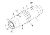
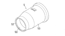
図1には、本発明の好ましい一実施形態に係るワンタッチ式管継手1の全体が示されている。図1を参照して理解されるように、本発明の管継手1はI字型に2つの接続管挿入ソケット2を有している。しかしながら、本発明の管継手は2つの接続管挿入ソケット2を有するタイプに限定されるものではなく、例えば一の側にのみ本発明による接続管挿入ソケット2を配置し、他の側には通常の受口または差口を形成させた1つの接続管挿入ソケット2のみを有するタイプや、T字型、十字型のように3つ以上の接続管挿入ソケット2を有するタイプの管継手も含まれる。また、異なる管径用の接続管挿入ソケット2を組み合わせた管継手も含まれている。
FIG. 1 shows the entirety of a one-touch type pipe joint 1 according to a preferred embodiment of the present invention. As can be understood with reference to FIG. 1, the pipe joint 1 of the present invention has two connecting
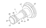
管継手1は管継手本体3、内筒体4、外筒体5、内側ロックリング6および外側ロックリング7から形成されており、いずれの部品も略筒状の形状を有している。また、本実施例では、管継手本体3は内筒体4を含み、射出成形により一体的に成形されている(図3参照)。管継手本体3および内筒体4はその内部に流体を流すための通路開口部30が形成されており、その先端部31は流体の抵抗を少なくするためにファンネル形状を有している。さらに、管継手1の生産性やコスト面などを重視する場合は、管継手本体3、内筒体4および外筒体5のすべての部品を射出成形等により一体的に成形することもできる。
The pipe joint 1 is formed of a pipe joint
継手本体3、内筒体4及び/又は外筒体5の材料は比較的硬質なものであれば特に限定されるものではないが、プラスチック材料または金属材料から成形されていることが好ましい。特にプラスチック材料を使用する場合は、ポリフェニルサルホン(PPSU)樹脂またはポリフェニレンサルファイド(PPS)樹脂であることが好ましい。
The material of the
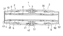
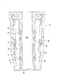
図2の中に示されるように、内筒体4の軸方向内部側にはフランジ41が形成されており、フランジ41の外縁42へ外筒体5の内周面50に形成された環状の連結溝51を遊嵌することにより、外筒体5は内筒体4を含む継手本体3に対し同心に摺動自在に装着される。そして内筒体4と外筒体5との間には接続管を受け入れるための収容部10が形成される。
As shown in FIG. 2, a
外筒体5を継手本体3および内筒体4へ上述の方法により装着すると、接続時若しくは接続後に接続管が受ける曲げ応力や回転モーメントを容易に逃がすことができるため、破壊応力に対し比較的柔軟に対応可能な管継手構造とすることができる。また、外筒体5を継手本体3へ回転不能に無理嵌めすることにより、全体として剛性の高い管継手構造とすることもできる。
When the outer
また、本実施例の外筒体5の先端52は、軸方向において内筒体4の先端43より外部側へ突出している。落下などによる外部衝撃から内筒体4を保護すると共に、万が一の場合、その破損の範囲を外筒体5に止め交換を容易にするためである。また、このような構造は、何らかの原因で接続管が管継手1の軸心に対し偏心するように変位してしまう場合、内筒体4の先端にかかる応力を低減し内筒体4が破損するのを効果的に防止する。
Further, the
管継手1の収容部10の中には、接続管挿入時、その内外周面を押圧する第1の爪部と、接続管引き抜き時、接続管を係止するために機能する第2の爪部とを有する内側ロックリング6および外側ロックリング7が軸方向に移動可能に配置される。ただし、本実施例において、ロックリングが内筒体4の外周面40および外筒体5の内周面50の両方に装着されている必要はなく、そのいずれか一方に装着されていればよい。しかしながら、管継手1の落下、溶剤の付着、踏み付けなどにより片方のロックリングが破損し得ることを考慮すると、本実施例のように内筒体4および外筒体5の両方に装着されていることが好ましい。
In the
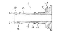
図3,4の中に示されるように、管継手1の内筒体4の外周面40には、内側ロックリング6を軸方向に移動可能に配置するため、径方向に平行な固定壁44と軸方向外部側へ向けて連続的に拡径しているテーパー壁45とが形成される。このため、内側ロックリング6は、内筒体4の固定壁44との関係で軸方向への移動が実質的に制限される固定端60を形成し、かつテーパー壁45との関係で軸方向への移動が許容される自由端61を形成するように固定壁44とテーパー壁45との間に装着される(図2参照)。また、内側ロックリング6の固定端60は自由端61より軸方向内部側へ配置されており、自由端61には引き抜き時、接続管を係止するための第2の外向き爪部65が配設される。
As shown in FIGS. 3 and 4, the
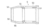
また、図5,6の中に示されるように、管継手1の外筒体5の内周面50には、外側ロックリング7を軸方向に移動可能に配置するため、径方向に平行な固定壁54と軸方向外部側へ向けて連続的に縮径しているテーパー壁55とが形成される。また、外筒体5の外周面53には、接続管から伝わる曲げ応力などに対抗するための補強リブ(図示せず)を設けてもよい。このため、外側ロックリング7は、外筒体5の固定壁54との関係で軸方向への移動が実質的に制限される固定端70を形成し、かつテーパー壁55との関係で軸方向への移動が許容される自由端71を形成するように固定壁54とテーパー壁55との間に装着される(図2参照)。また、外側ロックリング7の固定端70は自由端71より軸方向内部側へ配置されており、自由端71には引き抜き時、接続管を係止するための第2の内向き爪部75が配設される。
Further, as shown in FIGS. 5 and 6, the
図7,8には、本実施例の管継手1で使用される内側ロックリング6の斜視図および中心軸を通る断面で切り取った場合の断面図が示されている。
7 and 8 are a perspective view of the
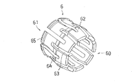
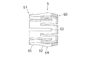
内筒体4の外周面40に配置される内側ロックリング6は、片持ちの自由端61を形成するために端部より複数のスリット63が切られた筒状体であって、接続管挿入時、弾性変形により接続管の内周面を押圧する第1の外向き爪部64と、上記自由端61に配置されており、接続管引き抜き時、接続管を係止するために機能する第2の外向き爪部65とを有している。
The
第1の外向き爪部64の押圧機構は、内側ロックリング6の爪部を支持する内側ロックリング自体の構造を弾性変形容易な構造とすることによって達成される。すなわち、内側ロックリング6の膨らみ部62はその断面形状においていわゆる尺取虫のような形状を有しているため、径方向内側へ向けて押圧されると撓み、その反力で挿入された接続管8の内周面80を適度に押圧する。また、スリット63は、内側ロックリング6の胴部を貫通するように軸方向に延びているため、スリット63により分割された膨らみ部62が互いに干渉するのを防止しながら弾性変形するのを容易化する。また、第1の外向き爪部64は、第2の外向き爪部65より軸方向内部側へ配置されているという特徴も有する。
The pressing mechanism of the first
また、内側ロックリング6の第1及び第2の外向き爪部64,65は、接続管の表面を押圧することにより、接続管へ係止若しくは接続管の抜けを防止するような形状であればよく、通常は単一または複数の爪状、歯状または鉤状の突起物からなる。本実施例の場合は、接続管の係止力や傷付け難さ、爪部の成形性や耐久性などを考慮して、接続管挿入側に緩斜面を有しその反対側に略垂直な急斜面を有する山脈形状の外向き爪部64,65を採用した。
Further, the first and second
その結果、図12を参照して理解されるように、接続管8を管継手1の収容部10の所定の位置まで挿入した後、引き抜き方向へ移動すると、内側ロックリング6も、第1の外向き爪部64が接続管8の内周面80に係止することにより接続管8と共に引き抜き方向へ移動する。そして内側ロックリング6の自由端61は内筒体4のテーパー壁45領域へ進入し、テーパー壁45との相互作用により第2の外向き爪部65を接続管8の内周面80へ押し付けるように拡径する。
As a result, as understood with reference to FIG. 12, when the connecting
このように本実施例の管継手1では、第1の外向き爪部64は挿入された接続管8の内周面80を適度に押圧するように内側ロックリング6の本体により支持されており、他方の接続管8の抜けを防止するために機能する第2の外向き爪部65は、接続管8を挿入後、引き抜き方向へ移動しない時、その内周面80と略接触しないように後退して内側ロックリング6の自由端61により支持されている。そして接続管8を挿入する際、接続管8が第1の外向き爪部64より受ける挿入抵抗は小さいが、接続管8が引き抜き方向へ移動すると、第2の外向き爪部65がテーパー壁45との相互作用により接続管8を確実かつ強固に係止する。
Thus, in the pipe joint 1 of the present embodiment, the first
また、挿入後の接続管8が引き抜き方向へ移動すると、内側ロックリング6は、第1の外向き爪部64の係止作用により必ず接続管8と共に引き抜き方向へ移動するため、本実施例の管継手1は、従来の移動式のロックリングを備えた管継手のようにロックリングを常に挿入口へ向けて付勢するためのバネなどを設ける必要もない。
Further, when the connecting
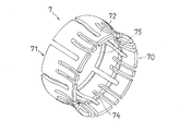
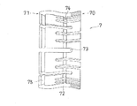
一方、図9,10には、本実施例の管継手1で使用される外側ロックリング7の斜視図および中心軸を通る断面で切り取った場合の断面図が示されている。
On the other hand, FIGS. 9 and 10 show a perspective view of the
外筒体5の内周面10に配置される外側ロックリング7は、上述された内側ロックリング6と同様に片持ちの自由端71を形成するために端部より複数のスリット73が切られた筒状体であって、接続管挿入時、弾性変形により接続管の外周面を押圧する第1の内向き爪部74と、上記自由端71に配置されており、接続管引き抜き時、接続管を係止するために機能する第2の内向き爪部75とを有している。
The
第1の内向き爪部74の押圧機構は、外側ロックリング7の爪部を支持する外側ロックリング自体の構造を弾性変形容易な構造とすることによって達成される。すなわち、外側ロックリング7のくびれ部72はその断面形状においていわゆる尺取虫のような形状を有しているため、径方向外側へ向けて押圧されると撓み、その反力で挿入された接続管8の外周面81を適度に押圧する。また、スリット73は、外側ロックリング7の胴部を貫通するように軸方向に延びているため、スリット73により分割されたくびれ部72が互いに干渉するのを防止しながら弾性変形するのを容易化する。また、第1の内向き爪部74は、第2の内向き爪部75より軸方向内部側へ配置されているという特徴も有する。
The pressing mechanism of the first
また、外側ロックリング7の第1及び第2の内向き爪部74,75は、接続管の表面を押圧することにより、接続管へ係止若しくは接続管の抜けを防止するような形状であればよく、通常は単一または複数の爪状、歯状または鉤状の突起物からなる。本実施例の場合は、接続の係止力や傷付け難さ、爪部の成形性や耐久性などを考慮して、接続管挿入側に緩斜面を有しその反対側に略垂直な急斜面を有する山脈形状の内向き爪部74,75を採用した。
Further, the first and second
その結果、図12を参照して理解されるように、接続管8を管継手1の収容部10の所定の位置まで挿入した後、引き抜き方向へ移動すると、外側ロックリング7も、第1の内向き爪部74が接続管8の外周面81に係止することにより接続管8と共に引き抜き方向へ移動する。そして外側ロックリング7の自由端71は外筒体5のテーパー壁55領域へ進入し、テーパー壁55との相互作用により第2の内向き爪部75を接続管8の外周面81へ押し付けるように縮径する。
As a result, as understood with reference to FIG. 12, when the connecting
このように本実施例の管継手1では、第1の内向き爪部74は挿入された接続管8の内周面80を適度に押圧するように外側ロックリング7の本体により支持されており、他方の接続管8の抜けを防止するために機能する第2の内向き爪部75は、接続管8を挿入後、引き抜き方向へ移動しない時、その外周面81と略接触しないように後退して外側ロックリング7の自由端71により支持されている。そして接続管8を挿入する際、接続管8が第1の内向き爪部74より受ける挿入抵抗は小さいが、接続管8が引き抜き方向へ移動すると、第2の内向き爪部75がテーパー壁55との相互作用により接続管8を確実かつ強固に係止する。
Thus, in the pipe joint 1 of the present embodiment, the first
また、挿入後の接続管8が引き抜き方向へ移動すると、外側ロックリング7は、第1の内向き爪部74の係止作用により必ず接続管8と共に引き抜き方向へ移動するため、本実施例の管継手1は、従来の移動式のロックリングを備えた管継手のようにロックリングを常に挿入口へ向けて付勢するためのバネなどを設ける必要もない。
Further, when the connecting
なお、管継手1へ接続した接続管8の取り外しを望む場合は、外筒体5の取り外しを可能としておけば、外筒体5を内筒体4から取り外すことにより外側ロックリング7による係止を解除することが可能となる。
If it is desired to remove the connecting
また、図11を参照して理解されるように、本実施例の管継手1では、接続管8の挿入前、内側ロックリング6および外側ロックリング7はそれらの自由端61,71がテーパー壁45,55領域へ進入しない長さの膨らみ部62またはくびれ部72を有している。このため、内側ロックリング6および外側ロックリング7の第2の爪部65,75は、接続管8挿入前、内筒体4の外周面40または外筒体5の内周面50より奥まった位置へ、すなわち、挿入される接続管8の内周面80または外周面81と略接触しない位置まで径方向内側または径方向外側へ後退している。
Further, as understood with reference to FIG. 11, in the pipe joint 1 of the present embodiment, before the
このため、本実施例の管継手1によれば、従来の移動式のロックリングを有するタイプの管継手や環状のロックリングが内部に固定されているタイプの管継手のように、接続管挿入時、接続管8の内周面80若しくは外周面81がロックリングの爪部により深く損傷を受けることが殆んどない。また、後述するシールリングとの相乗効果により高いシール効果や接続管8の強力な係止力を得ることもできる。
For this reason, according to the pipe joint 1 of the present embodiment, it is possible to insert a connecting pipe like a conventional pipe joint having a movable lock ring or a pipe joint in which an annular lock ring is fixed inside. At this time, the inner
本実施例の管継手1では、内側ロックリング6の第1の外向き爪部64と外側ロックリング7の第1の内向き爪部74が、軸方向において互いに異なる位置で接続管8を押圧するように配置されている(図11参照)。また、第1の外向き及び内向き爪部64,74と同様に内側ロックリング6の第2の外向き爪部65と外側ロックリングの7第2の内向き爪部75の場合も、軸方向において互いに異なる位置で接続管8を係止するように配置されている(図11参照)。
In the pipe joint 1 of the present embodiment, the first
このように、第1の外向き及び内向き爪部64,74が互いに異なる位置に配置されている場合、これらの爪64,74部を接続管8の内外周面80,81にソフトに接触させることができる。また、第1の外向き爪部64は内側ロックリング6の膨らみ部62の頂点に設けられており、第1の内向き爪部74は外側ロックリング7のくびれ部72の反対側の頂点に設けられているので、ロックリングの十分な可撓性を利用することができ、挿入抵抗の小さな管継手1を実現できる。
As described above, when the first outward and
また、本実施例の管継手1では、第2の外向き及び内向き爪部65,75も互いに異なる位置に配置されているので、図12(c)の中に示されるように爪部と対向する位置にシールリングなどのシール部材を配置することが可能となり、高いシール性を得ることができる。
Further, in the pipe joint 1 of the present embodiment, the second outward and
上述のような機能を達成し得るロックリング6,7の材料としては、硬質でかつ適度な弾性を有するものであれば特に限定されるものではないが、プラスチック材料または金属材料から成形することができる。特にプラスチック材料を使用する場合は、ポリフェニルサルホン(PPSU)樹脂またはポリフェニレンサルファイド(PPS)樹脂などのエンジニアリングプラスチック材料から成形されていることが好ましい。 The material of the lock rings 6 and 7 that can achieve the functions described above is not particularly limited as long as it is hard and has an appropriate elasticity, but it can be molded from a plastic material or a metal material. it can. In particular, when a plastic material is used, it is preferably molded from an engineering plastic material such as polyphenylsulfone (PPSU) resin or polyphenylene sulfide (PPS) resin.
本実施例の管継手1は、内筒体4の外周面40上に接続管8との間隙をシールするために2つのシールリング9,9’を備えている(図12(c)参照)。シールリング9,9’は、内筒体4の外周面40上に溝部46,46’を設け、その中に収容することにより固定される。また、シールリングの断面形状は特に制限がないが、本実施例ではO型の断面形状を有するシールリングを使用している。
The pipe joint 1 of the present embodiment is provided with two
シールリングは、内筒体4の外周面40上又は外筒体5の内周面50上若しくはそれらの両方の周面40,50上に配設することができるが、本実施例の管継手1の場合、極力外部から侵入するチリや埃の影響を排除し、かつ外筒体5が何らかの原因で破損した場合でもシール状態が維持できるようにする目的で、内筒体4の外周面40上にシールリング9,9’を配設している。また、このようなシールリング9,9’の配置は、管継手1へアルミニウム三層管のような円管が接続された場合、その端面において露出している金属部分が腐食するのを防止するのにも役立つ。
The seal ring can be disposed on the outer
シールリングは、本実施例のように内筒体4の外周面40上に2つ又はそれ以上配設してもよいが、少なくとも1つのシールリングを、無垢の接続管8の内周面80と接触させることにより高いシール性を確保するために、内側ロックリング6の第2の外向き爪部65より軸方向外部側へ配置することが好ましい。
Two or more seal rings may be disposed on the outer
さらに、シールリングは、先述したように外側ロックリング7の第2の内向き爪部75と対抗する位置に配置することにより、接続管装着後の第2の内向き爪部75の押付け力を利用してより強固なシールを得ることができる。また、シールリングを内筒体4の外周面40上に配設する場合、シールリングは内側ロックリング6の第2の外向き爪部65より軸方向外部側へ配置するのが損傷回避に有利であるから、この場合、内側ロックリング6の第2の外向き爪部65は、外側ロックリング7の第2の内向き爪部75より軸方向内部側に配置されることとなる。
Further, as described above, the seal ring is disposed at a position that opposes the second
また、装着後の接続管8のガタ付き減少を図る目的で、本実施例のシールリング9,9’は、それらが取付けられる同じ側の内側ロックリング6を挟むようにその前方と後方に分けて配置されている。
Further, for the purpose of reducing the backlash of the connecting
なお、図示しないが、本発明によれば、内側ロックリング6の第2の外向き爪部65と外側ロックリング7の第2の内向き爪部75を軸方向において互いに対向する位置で接続管8を係止するように配置してもよく、この場合、接続管8を内周面80および外周面81の対向し合う同じ位置から係止することができるので、極めて強固な接続が得られる。
Although not shown in the drawings, according to the present invention, the connecting pipe is provided at a position where the second
図12に示されるように、本実施例の管継手1の外筒体5は、接続管8が収容部10の所定の位置まで挿入されたことを確認するための挿入確認口56を備えている。挿入確認口56は外筒体5の表裏面を貫通する開口であって、外側ロックリング7より軸方向内部側へ配置される。また、挿入確認口56の中には、接続管8の挿入確認をより一層容易にするために、挿入確認口56の中にセットされる棒状部材101を備えたC形又はO形リングの部品102であって、接続管挿入時、前記リング部品102が接続管8の端部により奥方向へ押し込まれることにより、前記棒状部材101が外筒体5の外部から内部へ引き込まれるタイプの挿入確認手段100が管継手1の収容部10の中に配置されている。なお、挿入確認手段100は、他の図面の中では省略している。
As shown in FIG. 12, the
また、本実施例では省略しているが、本発明の管継手1は、リング状の部品であって、その一の端面(側面)には接続管8の先端を受け入れるためのリング状の溝部が形成されており、他の端面(側面)は、その縁部が面取りまたはRが施されている挿入ガイドリングを収容部10に配設することができる。
Although omitted in the present embodiment, the pipe joint 1 of the present invention is a ring-shaped component, and one end face (side face) of the pipe joint 1 is a ring-shaped groove for receiving the tip of the
挿入ガイドリングは、接続管挿入の際、その先端を覆って管継手1の収容部10の中を軸方向外部側から内部側へ向けて案内するため、接続管8の端部が鋭利に切り取られている場合であっても、内側および外側ロックリング6,7若しくはシールリング9,9’等を含む管継手1の収容部10が接続管8により損傷されるのを防止する。したがって、挿入ガイドリングはナイロン樹脂などの表面が滑らかな材料から成形されていることが好ましい。
The insertion guide ring covers the tip of the connection pipe when the connection pipe is inserted, and guides the inside of the
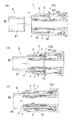
図12(a)〜(b)には、本発明の好ましい一実施形態に係るワンタッチ式管継手1の使用方法を示す概要図が示されている。(a)は接続管8の挿入前の状態を示し、(b)は挿入途中、接続管8の先端が内側ロックリング6の膨らみ部62の頂点に設けられた第1の外向き爪部64と、外側ロックリング7のくびれ部72の反対側の頂点に設けられた第1の内向き爪部74と当接している状態を示し、そして(c)は、接続管の挿入および固定が完了した状態を示している。
12A to 12B are schematic views showing how to use the one-touch type pipe joint 1 according to a preferred embodiment of the present invention. (A) shows a state before the
図12(a)および(b)の中に示されるように、接続管8は管継手1の挿入口11から収容部10の中へ挿入される。接続管8は、途中、内側ロックリング6の膨らみ部62に設けられた第1の外向き爪部64と、外側ロックリング7のくびれ部72に設けられた第1の内向き爪部74を径方向に押し広げながら、その先端が収容部10の中に配置されている挿入確認手段100と当接する。
As shown in FIGS. 12A and 12B, the
図12(c)の中に示されるように、接続管8はさらに収容部10の最深部まで押し込まれる。この時、内側ロックリング6および外側ロックリング7は、それぞれの膨らみ部62、くびれ部72に設けられた第1の外向き爪部64および第1の内向き爪部74により、接続管8の内周面80と外周面81へ係止される。このため、接続管8が挿入口11側(引き抜き方向)へ移動する時、内側ロックリング6および外側ロックリング7は接続管8の動きに追従して挿入口11側(引き抜き方向)へ移動する。そして内側ロックリング6の自由端61は内筒体4のテーパー壁45領域へ進入し、テーパー壁45との相互作用により第2の外向き爪部65を接続管8の内周面80へ押し付けるように拡径する。また、外側ロックリング7の自由端71は外筒体5のテーパー壁55領域へ進入し、テーパー壁55との相互作用により第2の内向き爪部75を接続管8の外周面81へ押し付けるように縮径する。
As shown in FIG. 12C, the
この結果、本実施例の管継手1では、接続管8は、接続管8を挿入する際、内側および外側ロックリング6,7の第1の外向き爪部64および第1の内向き爪部74より受ける挿入抵抗は小さいが、接続管8が引き抜き方向へ移動するとテーパー壁との相互作用により、第2の外向き爪部65および第2の内向き爪部75により確実かつ強固に係止される。
As a result, in the pipe joint 1 of the present embodiment, when the
また、接続管8が収容部10の最深部まで押し込まれると、挿入確認部材も接続管8の先端により収容部10の最深部まで押し込まれる。この結果、接続管挿入前は外筒体5の挿入確認口56から外部へ突出するようにセットされていた棒状部材101が管継手1の収容部11の中へ引き込まれるため、オペレーターは、接続管8が収容部10所定の位置まで挿入されて固定されていることを容易に確認することができる。
When the connecting
1 ・・・・・・・・・・・・・ ワンタッチ式管継手
2 ・・・・・・・・・・・・・ ソケット
3 ・・・・・・・・・・・・・ 管継手本体
30・・・・・・・・・・・・・ 通路開口部
31・・・・・・・・・・・・・ 先端部
4 ・・・・・・・・・・・・・ 内筒体
40・・・・・・・・・・・・・ 外周面
41・・・・・・・・・・・・・ フランジ
42・・・・・・・・・・・・・ 外縁
43・・・・・・・・・・・・・ 先端
44・・・・・・・・・・・・・ 固定壁
45・・・・・・・・・・・・・ テーパー壁
46,46’・・・・・ 溝部
5 ・・・・・・・・・・・・・ 外筒体
50・・・・・・・・・・・・・ 内周面
51・・・・・・・・・・・・・ 連結溝
52・・・・・・・・・・・・・ 先端
53・・・・・・・・・・・・・ 外周面
54・・・・・・・・・・・・・ 固定壁
55・・・・・・・・・・・・・ テーパー壁
56・・・・・・・・・・・・・ 挿入確認口
6 ・・・・・・・・・・・・・ 内側ロックリング
60・・・・・・・・・・・・・ 固定端
61・・・・・・・・・・・・・ 自由端
62・・・・・・・・・・・・・ 膨らみ部
63・・・・・・・・・・・・・ スリット
64・・・・・・・・・・・・・ 第1の外向き爪部
65・・・・・・・・・・・・・ 第2の外向き爪部
7 ・・・・・・・・・・・・・ 外側ロックリング
70・・・・・・・・・・・・・ 固定端
71・・・・・・・・・・・・・ 自由端
72・・・・・・・・・・・・・ くびれ部
73・・・・・・・・・・・・・ スリット
74・・・・・・・・・・・・・ 第1の内向き爪部
75・・・・・・・・・・・・・ 第2の内向き爪部
8 ・・・・・・・・・・・・・ 接続管
80・・・・・・・・・・・・・ 内周面
81・・・・・・・・・・・・・ 外周面
9,9’・・・・・・・・・ シールリング
10・・・・・・・・・・・・・ 収容部
11・・・・・・・・・・・・・ 挿入口
100・・・・・・・・・・・ 挿入確認手段
101・・・・・・・・・・・ 棒状部材
102・・・・・・・・・・・ リング部品
1 ························································································································································ 30 ... passage opening 31 ...
Claims (10)
径方向に平行な固定壁と、軸方向外部側へ向けて連続的に拡径するテーパー壁とを外周面に有し、そして前記継手本体から軸方向外部側へ向けて延びた内筒体と、
前記内筒体の外側へ配置され、前記内筒体との間に接続管を受け入れるための収容部を形成する外筒体と、そして
片持ちの自由端を形成するための複数のスリットを有する筒状体であって、前記接続管挿入時、前記筒状体の弾性変形により前記接続管の内周面を押圧する第1の外向き爪部と、前記自由端に配置されており、前記接続管引き抜き時、前記接続管を係止する第2の外向き爪部とを有し、そして前記内筒体の固定壁とテーパー壁との間で軸方向に移動可能に配置されている内側ロックリングを備えた管継手において、
前記接続管を前記収容部の所定の位置まで挿入後、引き抜き方向へ移動する時、前記内側ロックリングは、前記第1の外向き爪部が前記接続管の内周面に係止することにより前記接続管と共に引き抜き方向へ移動され、そして前記内側ロックリングの自由端は前記内筒体のテーパー壁領域へ進入し、前記テーパー壁との相互作用により前記第2の外向き爪部を前記接続管の内周面へ押し付けるように拡径されることを特徴とする管継手。 The fitting body;
A fixed wall parallel to the radial direction and a tapered wall continuously expanding toward the outer side in the axial direction on the outer peripheral surface; and an inner cylinder extending from the joint body toward the outer side in the axial direction ,
An outer cylinder which is disposed outside the inner cylinder and forms a receiving portion for receiving a connection pipe between the inner cylinder and a plurality of slits for forming a cantilever free end; A cylindrical body, and when the connecting pipe is inserted, the first outward claw portion that presses the inner peripheral surface of the connecting pipe by elastic deformation of the cylindrical body, and is disposed at the free end, An inner side having a second outward claw portion for locking the connection pipe when the connection pipe is pulled out, and is movably disposed in the axial direction between the fixed wall and the tapered wall of the inner cylindrical body In pipe fittings with lock rings,
When the connection tube is inserted to a predetermined position of the housing portion and then moved in the pulling direction, the inner lock ring is formed by the first outward claw portion being locked to the inner peripheral surface of the connection tube. The free end of the inner lock ring enters the tapered wall region of the inner cylinder and interacts with the tapered wall to connect the second outward claw portion with the connecting pipe. A pipe joint that is expanded in diameter so as to be pressed against the inner peripheral surface of the pipe.
前記継手本体から軸方向外部側へ向けて延びた内筒体と、
径方向に平行な固定壁と、軸方向外部側へ向けて連続的に縮径するテーパー壁とを内周面に有し、そして前記内筒体の外側へ配置され、前記内筒体との間に接続管を受け入れるための収容部を形成する外筒体と、そして
片持ちの自由端を形成するための複数のスリットを有する筒状体であって、前記接続管挿入時、前記筒状体の弾性変形により前記接続管の外周面を押圧する第1の内向き爪部と、前記自由端に配置されており、前記接続管引き抜き時、前記接続管を係止する第2の内向き爪部とを有し、そして前記外筒体の固定壁とテーパー壁との間で軸方向に移動可能に配置されている外側ロックリングを備えた管継手において、
前記接続管を前記収容部の所定の位置まで挿入後、引き抜き方向へ移動する時、前記外側ロックリングは、前記第1の内向き爪部が前記接続管の外周面に係止することにより前記接続管と共に引き抜き方向へ移動され、そして前記外側ロックリングの自由端は前記外筒体のテーパー壁領域へ進入し、前記テーパー壁との相互作用により前記第2の内向き爪部を前記接続管の外周面へ押し付けるように縮径されることを特徴とする管継手。 The fitting body;
An inner cylinder extending from the joint body toward the outside in the axial direction;
A fixed wall parallel to the radial direction and a tapered wall continuously reducing in diameter toward the outer side in the axial direction are provided on the inner peripheral surface, and disposed on the outer side of the inner cylindrical body. A cylindrical body having an outer cylindrical body for receiving a connecting pipe therebetween and a plurality of slits for forming a cantilevered free end when the connecting pipe is inserted; A first inward claw portion that presses the outer peripheral surface of the connection pipe by elastic deformation of the body, and a second inward position that is disposed at the free end and locks the connection pipe when the connection pipe is pulled out And a pipe joint including an outer lock ring that is arranged so as to be movable in the axial direction between the fixed wall and the tapered wall of the outer cylinder.
When the connecting pipe is inserted to a predetermined position of the housing part and then moved in the pulling direction, the outer lock ring is configured such that the first inward claw part is locked to the outer peripheral surface of the connecting pipe. It is moved together with the connecting pipe in the pulling direction, and the free end of the outer lock ring enters the tapered wall region of the outer cylindrical body, and the second inward claw portion is connected to the connecting pipe by interaction with the tapered wall. The pipe joint is reduced in diameter so as to be pressed against the outer peripheral surface of the pipe.
径方向に平行な固定壁と、軸方向外部側へ向けて連続的に拡径するテーパー壁とを外周面に有し、そして前記継手本体から軸方向外部側へ向けて延びた内筒体と、
径方向に平行な固定壁と、軸方向外部側へ向けて連続的に縮径するテーパー壁とを内周面に有し、そして前記内筒体の外側へ配置され、前記内筒体との間に接続管を受け入れるための収容部を形成する外筒体と、
片持ちの自由端を形成するための複数のスリットを有する筒状体であって、前記接続管挿入時、前記筒状体の弾性変形により前記接続管の内周面を押圧する第1の外向き爪部と、前記自由端に配置されており、前記接続管引き抜き時、前記接続管を係止する第2の外向き爪部とを有し、そして前記内筒体の固定壁とテーパー壁との間で軸方向に移動可能に配置されている内側ロックリングと、そして
片持ちの自由端を形成するための複数のスリットを有する筒状体であって、前記接続管挿入時、前記筒状体の弾性変形により前記接続管の外周面を押圧する第1の内向き爪部と、前記自由端に配置されており、前記接続管引き抜き時、前記接続管を係止する第2の内向き爪部とを有し、そして前記外筒体の固定壁とテーパー壁との間で軸方向に移動可能に配置されている外側ロックリングを備えた管継手において、
前記接続管を前記収容部の所定の位置まで挿入後、引き抜き方向へ移動する時、前記内側ロックリングは、前記第1の外向き爪部が前記接続管の内周面に係止することにより前記接続管と共に引き抜き方向へ移動され、そして前記内側ロックリングの自由端は前記内筒体のテーパー壁領域へ進入し、前記テーパー壁との相互作用により前記第2の外向き爪部を前記接続管の内周面へ押し付けるように拡径され、かつ前記外側ロックリングは、前記第1の内向き爪部が前記接続管の外周面に係止することにより前記接続管と共に引き抜き方向へ移動され、そして前記外側ロックリングの自由端は前記外筒体のテーパー壁領域へ進入し、前記テーパー壁との相互作用により前記第2の内向き爪部を前記接続管の外周面へ押し付けるように縮径されることを特徴とする管継手。 The fitting body;
A fixed wall parallel to the radial direction and a tapered wall continuously expanding toward the outer side in the axial direction on the outer peripheral surface; and an inner cylinder extending from the joint body toward the outer side in the axial direction ,
A fixed wall parallel to the radial direction and a tapered wall continuously reducing in diameter toward the outer side in the axial direction are provided on the inner peripheral surface, and disposed on the outer side of the inner cylindrical body. An outer cylinder forming a housing for receiving the connecting pipe therebetween,
A cylindrical body having a plurality of slits for forming a cantilevered free end, the first outer surface pressing the inner peripheral surface of the connection pipe by elastic deformation of the cylindrical body when the connection pipe is inserted A claw portion that is disposed at the free end, and has a second outward claw portion that locks the connection pipe when the connection pipe is pulled out, and a fixed wall and a tapered wall of the inner cylinder A cylindrical body having an inner lock ring arranged so as to be movable in the axial direction and a plurality of slits for forming a cantilevered free end when the connecting pipe is inserted. A first inward claw portion that presses the outer peripheral surface of the connecting pipe by elastic deformation of the body, and a second inner hook that is disposed at the free end and locks the connecting pipe when the connecting pipe is pulled out. And an axial direction between the fixed wall and the taper wall of the outer cylinder. In a pipe fitting with an outer lock ring arranged movably,
When the connection tube is inserted to a predetermined position of the housing portion and then moved in the pulling direction, the inner lock ring is formed by the first outward claw portion being locked to the inner peripheral surface of the connection tube. The free end of the inner lock ring enters the tapered wall region of the inner cylinder and interacts with the tapered wall to connect the second outward claw portion with the connecting pipe. The outer lock ring is expanded so as to press against the inner peripheral surface of the tube, and the outer lock ring is moved in the pulling direction together with the connection tube when the first inward claw portion is engaged with the outer peripheral surface of the connection tube. The free end of the outer lock ring enters the tapered wall region of the outer cylinder, and is compressed so as to press the second inward claw portion against the outer peripheral surface of the connecting pipe by interaction with the tapered wall. Diameter Pipe fitting, characterized in that.
Priority Applications (1)
| Application Number | Priority Date | Filing Date | Title |
|---|---|---|---|
| JP2009242397A JP5334792B2 (en) | 2009-10-21 | 2009-10-21 | Pipe fitting |
Applications Claiming Priority (1)
| Application Number | Priority Date | Filing Date | Title |
|---|---|---|---|
| JP2009242397A JP5334792B2 (en) | 2009-10-21 | 2009-10-21 | Pipe fitting |
Publications (2)
| Publication Number | Publication Date |
|---|---|
| JP2011089565A JP2011089565A (en) | 2011-05-06 |
| JP5334792B2 true JP5334792B2 (en) | 2013-11-06 |
Family
ID=44107997
Family Applications (1)
| Application Number | Title | Priority Date | Filing Date |
|---|---|---|---|
| JP2009242397A Expired - Fee Related JP5334792B2 (en) | 2009-10-21 | 2009-10-21 | Pipe fitting |
Country Status (1)
| Country | Link |
|---|---|
| JP (1) | JP5334792B2 (en) |
Cited By (1)
| Publication number | Priority date | Publication date | Assignee | Title |
|---|---|---|---|---|
| WO2020001029A1 (en) * | 2018-06-27 | 2020-01-02 | 日丰企业(佛山)有限公司 | Outer seal connection pipe fitting and pipeline |
Families Citing this family (6)
| Publication number | Priority date | Publication date | Assignee | Title |
|---|---|---|---|---|
| AT512772B1 (en) * | 2012-09-10 | 2013-11-15 | Ke Kelit Kunststoffwerk Gmbh | Plug-in coupling for a metallic pipe, in particular for water pipes |
| JP2015209911A (en) * | 2014-04-25 | 2015-11-24 | アロン化成株式会社 | Adapter for fittings |
| WO2018184371A1 (en) * | 2017-04-07 | 2018-10-11 | 上海飞斯耐暖通科技有限公司 | New type of rapid pipe joint |
| CN106838517B (en) * | 2017-04-07 | 2018-09-07 | 上海飞斯耐暖通科技有限公司 | A kind of novel quick coupling |
| CN111365545A (en) * | 2020-03-31 | 2020-07-03 | 黄晓峰 | A quick-insertion pipe fitting for a flexible tube |
| CN115788816B (en) * | 2022-12-23 | 2024-02-02 | 中山市宝悦嘉电子有限公司 | Automatic metering equipment for adding developing liquid medicine |
Family Cites Families (9)
| Publication number | Priority date | Publication date | Assignee | Title |
|---|---|---|---|---|
| DE3905722A1 (en) * | 1989-01-25 | 1990-07-26 | Festo Kg | CONNECTING DEVICE |
| JPH1151274A (en) * | 1997-07-30 | 1999-02-26 | Sekisui Chem Co Ltd | Pipe fitting and method of assembling the same |
| JPH11223288A (en) * | 1998-02-05 | 1999-08-17 | Bridgestone Flowtech Corp | Structure of fitting |
| JP2001021087A (en) * | 1999-07-08 | 2001-01-26 | Sekisui Chem Co Ltd | Pipe fittings |
| JP4179919B2 (en) * | 2003-04-28 | 2008-11-12 | 積水化学工業株式会社 | Pipe fitting |
| JP4391222B2 (en) * | 2003-12-22 | 2009-12-24 | ブリヂストンフローテック株式会社 | Pipe fitting |
| JP2006118704A (en) * | 2004-09-21 | 2006-05-11 | Hitachi Metals Ltd | Insertion type joint |
| NL1029408C2 (en) * | 2005-07-01 | 2007-01-04 | Wavin Bv | Pipe coupling. |
| JP4962849B2 (en) * | 2006-11-30 | 2012-06-27 | 日立金属株式会社 | Pipe fitting |
-
2009
- 2009-10-21 JP JP2009242397A patent/JP5334792B2/en not_active Expired - Fee Related
Cited By (1)
| Publication number | Priority date | Publication date | Assignee | Title |
|---|---|---|---|---|
| WO2020001029A1 (en) * | 2018-06-27 | 2020-01-02 | 日丰企业(佛山)有限公司 | Outer seal connection pipe fitting and pipeline |
Also Published As
| Publication number | Publication date |
|---|---|
| JP2011089565A (en) | 2011-05-06 |
Similar Documents
| Publication | Publication Date | Title |
|---|---|---|
| JP5334792B2 (en) | Pipe fitting | |
| JP5286129B2 (en) | Pipe fitting | |
| EP2503207B1 (en) | Pipe joint | |
| CN102691836B (en) | Pipe joint | |
| JP4174738B2 (en) | Hose fittings | |
| EP1074781B1 (en) | Pipe joint | |
| IT9067767A1 (en) | CONNECTOR FOR PIPES | |
| JP4906973B1 (en) | Pipe fitting | |
| WO2014010235A1 (en) | Connector | |
| EP2508784B1 (en) | Pipe Coupling | |
| JP5486895B2 (en) | Pipe fitting | |
| CN102099610A (en) | Plug connections for pressure medium lines | |
| CN102544883B (en) | Guy rope dropping connector | |
| JPWO2009150739A1 (en) | Pipe fitting | |
| KR101681787B1 (en) | Pipe joint | |
| JPH11201347A (en) | Pipe fittings | |
| JP2018115739A (en) | Pipe joint | |
| JP4444878B2 (en) | Piping joint | |
| JP2018109422A (en) | Pipe joint | |
| JP6370721B2 (en) | CONNECTING DEVICE AND CONCRETE MEMBER CONNECTING DEVICE USING THE SAME | |
| JP2013221586A (en) | Pipe joint | |
| JP4873604B2 (en) | Pipe fitting | |
| JPS6110077Y2 (en) | ||
| JP2002213664A (en) | Pipe fittings | |
| JP2006009997A (en) | Tube fitting |
Legal Events
| Date | Code | Title | Description |
|---|---|---|---|
| A621 | Written request for application examination |
Free format text: JAPANESE INTERMEDIATE CODE: A621 Effective date: 20120529 |
|
| A977 | Report on retrieval |
Free format text: JAPANESE INTERMEDIATE CODE: A971007 Effective date: 20130711 |
|
| TRDD | Decision of grant or rejection written | ||
| A01 | Written decision to grant a patent or to grant a registration (utility model) |
Free format text: JAPANESE INTERMEDIATE CODE: A01 Effective date: 20130723 |
|
| A61 | First payment of annual fees (during grant procedure) |
Free format text: JAPANESE INTERMEDIATE CODE: A61 Effective date: 20130730 |
|
| R150 | Certificate of patent or registration of utility model |
Ref document number: 5334792 Country of ref document: JP Free format text: JAPANESE INTERMEDIATE CODE: R150 Free format text: JAPANESE INTERMEDIATE CODE: R150 |
|
| R250 | Receipt of annual fees |
Free format text: JAPANESE INTERMEDIATE CODE: R250 |
|
| R250 | Receipt of annual fees |
Free format text: JAPANESE INTERMEDIATE CODE: R250 |
|
| R250 | Receipt of annual fees |
Free format text: JAPANESE INTERMEDIATE CODE: R250 |
|
| R250 | Receipt of annual fees |
Free format text: JAPANESE INTERMEDIATE CODE: R250 |
|
| R250 | Receipt of annual fees |
Free format text: JAPANESE INTERMEDIATE CODE: R250 |
|
| LAPS | Cancellation because of no payment of annual fees |