JP4980585B2 - 処理装置内の胴の直接駆動装置用位置センサ - Google Patents
処理装置内の胴の直接駆動装置用位置センサ Download PDFInfo
- Publication number
- JP4980585B2 JP4980585B2 JP2005135448A JP2005135448A JP4980585B2 JP 4980585 B2 JP4980585 B2 JP 4980585B2 JP 2005135448 A JP2005135448 A JP 2005135448A JP 2005135448 A JP2005135448 A JP 2005135448A JP 4980585 B2 JP4980585 B2 JP 4980585B2
- Authority
- JP
- Japan
- Prior art keywords
- cylinder
- position sensor
- rotary joint
- direct drive
- joint
- Prior art date
- Legal status (The legal status is an assumption and is not a legal conclusion. Google has not performed a legal analysis and makes no representation as to the accuracy of the status listed.)
- Expired - Fee Related
Links
Images


Classifications
-
- B—PERFORMING OPERATIONS; TRANSPORTING
- B41—PRINTING; LINING MACHINES; TYPEWRITERS; STAMPS
- B41F—PRINTING MACHINES OR PRESSES
- B41F33/00—Indicating, counting, warning, control or safety devices
- B41F33/04—Tripping devices or stop-motions
- B41F33/14—Automatic control of tripping devices by feelers, photoelectric devices, pneumatic devices, or other detectors
Landscapes
- Inking, Control Or Cleaning Of Printing Machines (AREA)
- Rotary Presses (AREA)
- Spray Control Apparatus (AREA)
Description
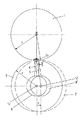
2 ゴム胴
3 被印刷物案内胴
4 版胴 (formzylinder)
5 インキロール
6 第1伝動要素
7 第2伝動要素
8 回転継手
9 フレーム固定回転継手
10 自由回転継手
11 直進継手
12 変位可能な胴軸
13 位置センサ
14 固定軸位置
15 第3伝動要素
16 第4伝動要素
17 係合要素(ローラ)
18 カム継手
19 カム支持体
20 第1結合リンク
21 第2結合リンク
22 フレーム固定回転継手
23 自由回転継手
r 半径(胴の)
x 行程
y 行程
Claims (12)
- 処理装置内の胴の直接駆動装置用位置センサ装置であって、位置センサの信号によって第1胴の直接駆動装置が、隣接する別途駆動可能な第2胴に対して同期角度動作で制御可能であるものにおいて、
胴(2;4)の変位可能な胴軸(12)上で位置センサ(13)が回転継手(8)の一部を構成して設けられており、かつ該位置センサ(13)は機構的伝動手段(6,7;6,11)によってフレーム固定回転継手(9)と連結されており、前記機構的伝動手段を構成する第1伝動要素(6)が、双方の胴(1,2;3,4)の接触域の高さにまで自身の長手方向が延在するよう構成され、かつ該第1伝動要素の末端に、前記機構的伝動手段を構成して前記フレーム固定回転継手(9)と連結された第2伝動要素(7;11)が配置されていることを特徴とする位置センサ装置。 - 変位可能な胴軸(12)を有する胴(2;4)が、直接駆動装置に連結された版胴(1)と機能結合されたゴム胴(2)であることを特徴とする請求項1記載の位置センサ装置。
- 変位可能な胴軸(12)を有する胴(2;4)が独自の直接駆動装置に連結された版胴(4)であり、別途駆動可能な胴が被印刷物案内胴(3)であることを特徴とする請求項1記載の位置センサ装置。
- 前記第1伝動要素(6)と前記第2伝動要素(7)とが自由回転継手(10)によって結合されることによりダブルリンクを構成していることを特徴とする請求項1記載の位置センサ装置。
- 前記第2伝動要素が直進継手(11)であり、該直進継手が前記フレーム固定回転継手(9)と連結されていることを特徴とする請求項1記載の位置センサ装置。
- 第1伝動要素(6)がステーであり、第2伝動要素(7)がステーに結合された板バネであることを特徴とする、請求項1記載の位置センサ装置。
- 処理装置内の胴の直接駆動装置用位置センサ装置であって、位置センサの信号によって第1胴の直接駆動装置が、隣接する別途駆動可能な第2胴に対して同期角度動作で制御可能であるものにおいて、
固定軸位置(14)を有する胴(1、3)上で位置センサ(13)が回転継手(8)の一部を構成して設けられており、かつ該位置センサ(13)は、カム継手(18)を含む機構的伝動手段(15,16,17,18,19,20)によってフレーム固定回転継手(9)と連結されており、
前記カム継手(18)を構成する伝動要素(16)及び該伝動要素(16)に固定付設された結合リンク(20)がフレーム固定回転継手(9)に連結されており、この結合リンク(20)は胴(2,4)の変位可能な胴軸(12)に配置される回転継手(8)と連結されていることを特徴とする位置センサ装置。 - 処理装置内の胴の直接駆動装置用位置センサ装置であって、位置センサの信号によって第1胴の直接駆動装置が、隣接する別途駆動可能な第2胴に対して同期角度動作で制御可能であるものにおいて、
固定軸位置(14)を有する胴(1,3)上で位置センサ(13)が回転継手(8)の一部を構成して設けられており、かつ該位置センサ(13)は、カム継手(18)を含む機構的伝動手段(15,16,17,18,19,20)によってフレーム固定回転継手(9)と連結されており、
前記カム継手(18)を構成する伝動要素(16)は、結合リンク(20)と強固に連結されるとともに、変位可能な胴軸(12)の回転継手(8)に連結されており、前記結合リンク(20)はフレーム固定回転継手(9)に連結されていることを特徴とする位置センサ装置。 - 処理装置内の胴の直接駆動装置用位置センサ装置であって、位置センサの信号によって第1胴の直接駆動装置が、隣接する別途駆動可能な第2胴に対して同期角度動作で制御可能であるものにおいて、
胴(2,4)の変位可能な胴軸(12)上で位置センサ(13)が、四つの回転継手連鎖(8,9,22,23;15,20,21)のうちの1つの回転継手(8)の一部を構成して設けられており、前記回転継手連鎖のうち別の2つの回転継手(9、22)がフレーム固定要素を形成することを特徴とする位置センサ装置。 - 処理装置内の胴の直接駆動装置用位置センサ装置であって、位置センサの信号によって第1胴の直接駆動装置が、隣接する別途駆動可能な第2胴に対して同期角度動作で制御可能であるものにおいて、
胴(2,4)の変位可能な胴軸(12)上で位置センサ(13)が回転継手(8)の一部を構成して設けられており、結合リンク(20)が胴軸(12)に枢着されかつ回転可能にフレーム固定回転継手(9)と結合されており、前記位置センサ(13)は伝動要素(15)を有し、該伝動要素(15)によって、他のフレーム固定回転継手(22)と連結された直進継手(11)内で案内され、かつ前記伝動要素(15)は、変位可能な胴軸(12)を有する胴(2,4)と固定軸位置(14)を有する胴(1,3)との間の接触域内で支えられていることを特徴とする位置センサ装置。 - 変位可能な胴軸(12)を有する胴(2;4)が、直接駆動装置に連結された版胴(1)と機能結合されたゴム胴(2)であることを特徴とする請求項7〜10の何れか1項記載の位置センサ装置。
- 変位可能な胴軸(12)を有する胴(2;4)が独自の直接駆動装置に連結された版胴(4)であり、別途駆動可能な胴が被印刷物案内胴(3)であることを特徴とする請求項7〜10の何れか1項記載の位置センサ装置。
Applications Claiming Priority (4)
| Application Number | Priority Date | Filing Date | Title |
|---|---|---|---|
| DE102004022699 | 2004-05-05 | ||
| DE102004022699.7 | 2004-05-05 | ||
| DE102005018528.2A DE102005018528C5 (de) | 2004-05-05 | 2005-04-20 | Lagegeber für einen Direktantrieb eines Zylinders in einer Verarbeitungsmaschine |
| DE102005018528.2 | 2005-04-20 |
Publications (2)
| Publication Number | Publication Date |
|---|---|
| JP2005319805A JP2005319805A (ja) | 2005-11-17 |
| JP4980585B2 true JP4980585B2 (ja) | 2012-07-18 |
Family
ID=34935609
Family Applications (1)
| Application Number | Title | Priority Date | Filing Date |
|---|---|---|---|
| JP2005135448A Expired - Fee Related JP4980585B2 (ja) | 2004-05-05 | 2005-05-06 | 処理装置内の胴の直接駆動装置用位置センサ |
Country Status (4)
| Country | Link |
|---|---|
| EP (1) | EP1593510B1 (ja) |
| JP (1) | JP4980585B2 (ja) |
| CN (1) | CN100537236C (ja) |
| DE (1) | DE102005018528C5 (ja) |
Families Citing this family (6)
| Publication number | Priority date | Publication date | Assignee | Title |
|---|---|---|---|---|
| DE102005053162A1 (de) * | 2005-11-08 | 2007-05-10 | Man Roland Druckmaschinen Ag | Druckmaschine und Verfahren zum Betreiben derselben |
| DE102006053473B4 (de) * | 2006-11-14 | 2009-12-10 | Manroland Ag | Anordnung eines Lagegebers auf einer Welle eines antreibbaren Zylinders in einer Verarbeitungsmaschine |
| DE102008054854A1 (de) | 2007-12-22 | 2009-06-25 | Koenig & Bauer Aktiengesellschaft | Verfahren und Anordnung zur Kompensation von regelungsbedingten Drehwinkel-Asynchronitäten |
| DE102008001003B3 (de) * | 2008-04-04 | 2009-02-26 | Manroland Ag | Bedruckstoff verarbeitende Rotationsdruckmaschine |
| DE102010000997B4 (de) * | 2010-01-19 | 2014-02-27 | Koenig & Bauer Aktiengesellschaft | Druckeinheiten einer Druckmaschine |
| DE102022102028A1 (de) | 2022-01-28 | 2023-08-03 | Koenig & Bauer Ag | Verarbeitungswerk und Verfahren zum Betreiben eines Verarbeitungswerkes einer Verarbeitungsmaschine |
Family Cites Families (9)
| Publication number | Priority date | Publication date | Assignee | Title |
|---|---|---|---|---|
| DE4138479C3 (de) * | 1991-11-22 | 1998-01-08 | Baumueller Nuernberg Gmbh | Verfahren und Anordnung für einen Elektromotor zum Antrieb eines Drehkörpers, insbesondere des druckgebenden Zylinders einer Druckmaschine |
| DE19614818A1 (de) * | 1996-04-15 | 1997-10-16 | Wifag Maschf | Drehgeber für einen Zylinder einer Druckmaschine |
| DE19623224C1 (de) * | 1996-06-11 | 1997-09-11 | Roland Man Druckmasch | Antrieb für eine Druckmaschine |
| DE19635796C2 (de) * | 1996-09-04 | 1998-07-02 | Roland Man Druckmasch | Befestigung für einen Drehgeber |
| DE19720952C2 (de) * | 1997-05-17 | 2001-02-01 | Roland Man Druckmasch | Schwenkbarer, durch einen elektrischen Einzelantrieb angetriebener Zylinder |
| DE19803558A1 (de) * | 1998-01-30 | 1999-08-12 | Koenig & Bauer Ag | Verfahren zur Ermittlung einer Winkellage eines ortsveränderbaren Zylinders einer Druckmaschine |
| JP2001129971A (ja) * | 1999-11-08 | 2001-05-15 | Mitsubishi Heavy Ind Ltd | 印刷機の駆動装置 |
| DE10327423B4 (de) * | 2002-07-12 | 2008-07-17 | Heidelberger Druckmaschinen Ag | Antrieb für eine Rotationsdruckmaschine |
| DE10304495B4 (de) * | 2003-02-05 | 2015-04-16 | Koenig & Bauer Aktiengesellschaft | Verfahren und Anordnung für die Synchronisierung eines elektrischen Einzelantriebes |
-
2005
- 2005-04-20 DE DE102005018528.2A patent/DE102005018528C5/de active Active
- 2005-04-22 EP EP05008880.6A patent/EP1593510B1/de active Active
- 2005-05-06 JP JP2005135448A patent/JP4980585B2/ja not_active Expired - Fee Related
- 2005-05-08 CN CN 200510076283 patent/CN100537236C/zh not_active Expired - Fee Related
Also Published As
| Publication number | Publication date |
|---|---|
| EP1593510B1 (de) | 2018-09-05 |
| DE102005018528B4 (de) | 2012-12-06 |
| CN100537236C (zh) | 2009-09-09 |
| JP2005319805A (ja) | 2005-11-17 |
| DE102005018528C5 (de) | 2019-03-14 |
| CN1704239A (zh) | 2005-12-07 |
| DE102005018528A1 (de) | 2005-12-08 |
| EP1593510A2 (de) | 2005-11-09 |
| EP1593510A3 (de) | 2006-06-07 |
Similar Documents
| Publication | Publication Date | Title |
|---|---|---|
| JP4980585B2 (ja) | 処理装置内の胴の直接駆動装置用位置センサ | |
| JP4664583B2 (ja) | 枚葉紙を処理する機械に設けられたグリッパ装置 | |
| US4524712A (en) | Varnish coater for printed product | |
| EP1882590A1 (en) | Register adjusting device of rotary body | |
| US6293194B1 (en) | Method and apparatus for adjusting the circumferential register in a web-fed rotary printing press having a plate cylinder with a sleeve-shaped printing plate | |
| EP0513756B2 (en) | Printing pressure adjusting apparatus of printing cylinders | |
| JP4499324B2 (ja) | アクチュエータ式のプレグリッパ制御装置 | |
| JP4970721B2 (ja) | 印刷機を通ってシートを搬送するための装置 | |
| JP2007503333A (ja) | 多色輪転印刷機における印刷ギャップを通って走行する材料ウェブにおけるレジスタエラーを低減する方法および装置 | |
| JP4759101B2 (ja) | 印刷機の印刷部に設けられた装置 | |
| JP4436114B2 (ja) | 印刷機の印圧調整装置 | |
| EP1031418B1 (en) | Sheet-like object conveying apparatus for sheet-fed rotary printing press | |
| JP2009096200A (ja) | 枚葉紙印刷機の印刷ユニットの間の渡し胴 | |
| JP3720630B2 (ja) | 多色式オフセット輪転機の調幅装置 | |
| JP3164710U (ja) | 枚葉紙処理用の機械のグリッパ装置の開閉のための装置 | |
| CN1085146C (zh) | 用于辊子到位印刷和离位停印的装置 | |
| EP1516728B1 (en) | Cylinder apparatus | |
| JP2004050849A (ja) | 印刷機で押し当てと押し離しをする装置 | |
| JP4469548B2 (ja) | 印刷用の機械へ枚葉紙を供給するための方法及び装置 | |
| JPH04224948A (ja) | 多色・枚葉紙輪転印刷機における枚葉紙渡しドラムに設けられた吸込制御装置 | |
| US5611277A (en) | Sheet-conveying drum for printing machines | |
| US8356812B2 (en) | Apparatus for correcting the position of sheets | |
| JP2007307905A (ja) | 枚葉紙印刷機の運転方法 | |
| JP3978151B2 (ja) | 枚葉印刷機の紙咥え装置 | |
| JP4451532B2 (ja) | 枚葉輪転印刷機のシート状物搬送装置 |
Legal Events
| Date | Code | Title | Description |
|---|---|---|---|
| A621 | Written request for application examination |
Free format text: JAPANESE INTERMEDIATE CODE: A621 Effective date: 20080125 |
|
| A977 | Report on retrieval |
Free format text: JAPANESE INTERMEDIATE CODE: A971007 Effective date: 20101201 |
|
| A131 | Notification of reasons for refusal |
Free format text: JAPANESE INTERMEDIATE CODE: A131 Effective date: 20101214 |
|
| A521 | Request for written amendment filed |
Free format text: JAPANESE INTERMEDIATE CODE: A523 Effective date: 20110302 |
|
| A131 | Notification of reasons for refusal |
Free format text: JAPANESE INTERMEDIATE CODE: A131 Effective date: 20110927 |
|
| A521 | Request for written amendment filed |
Free format text: JAPANESE INTERMEDIATE CODE: A523 Effective date: 20111222 |
|
| TRDD | Decision of grant or rejection written | ||
| A01 | Written decision to grant a patent or to grant a registration (utility model) |
Free format text: JAPANESE INTERMEDIATE CODE: A01 Effective date: 20120321 |
|
| A01 | Written decision to grant a patent or to grant a registration (utility model) |
Free format text: JAPANESE INTERMEDIATE CODE: A01 |
|
| A61 | First payment of annual fees (during grant procedure) |
Free format text: JAPANESE INTERMEDIATE CODE: A61 Effective date: 20120419 |
|
| FPAY | Renewal fee payment (event date is renewal date of database) |
Free format text: PAYMENT UNTIL: 20150427 Year of fee payment: 3 |
|
| R150 | Certificate of patent or registration of utility model |
Ref document number: 4980585 Country of ref document: JP Free format text: JAPANESE INTERMEDIATE CODE: R150 Free format text: JAPANESE INTERMEDIATE CODE: R150 |
|
| FPAY | Renewal fee payment (event date is renewal date of database) |
Free format text: PAYMENT UNTIL: 20150427 Year of fee payment: 3 |
|
| S111 | Request for change of ownership or part of ownership |
Free format text: JAPANESE INTERMEDIATE CODE: R313113 |
|
| FPAY | Renewal fee payment (event date is renewal date of database) |
Free format text: PAYMENT UNTIL: 20150427 Year of fee payment: 3 |
|
| R350 | Written notification of registration of transfer |
Free format text: JAPANESE INTERMEDIATE CODE: R350 |
|
| R250 | Receipt of annual fees |
Free format text: JAPANESE INTERMEDIATE CODE: R250 |
|
| R250 | Receipt of annual fees |
Free format text: JAPANESE INTERMEDIATE CODE: R250 |
|
| R250 | Receipt of annual fees |
Free format text: JAPANESE INTERMEDIATE CODE: R250 |
|
| R250 | Receipt of annual fees |
Free format text: JAPANESE INTERMEDIATE CODE: R250 |
|
| R250 | Receipt of annual fees |
Free format text: JAPANESE INTERMEDIATE CODE: R250 |
|
| R250 | Receipt of annual fees |
Free format text: JAPANESE INTERMEDIATE CODE: R250 |
|
| R250 | Receipt of annual fees |
Free format text: JAPANESE INTERMEDIATE CODE: R250 |
|
| LAPS | Cancellation because of no payment of annual fees |