JP4859397B2 - Bullet ball machine - Google Patents
Bullet ball machine Download PDFInfo
- Publication number
- JP4859397B2 JP4859397B2 JP2005178223A JP2005178223A JP4859397B2 JP 4859397 B2 JP4859397 B2 JP 4859397B2 JP 2005178223 A JP2005178223 A JP 2005178223A JP 2005178223 A JP2005178223 A JP 2005178223A JP 4859397 B2 JP4859397 B2 JP 4859397B2
- Authority
- JP
- Japan
- Prior art keywords
- setting
- game
- display result
- value
- state
- Prior art date
- Legal status (The legal status is an assumption and is not a legal conclusion. Google has not performed a legal analysis and makes no representation as to the accuracy of the status listed.)
- Expired - Fee Related
Links
Images


Description
本発明は、所定の始動条件の成立にもとづいて各々が識別可能な複数種類の識別情報の可変表示を行って表示結果を導出表示する可変表示部を備え、該可変表示部の表示結果が予め定められた特定表示結果となったときに遊技者にとって有利な特定遊技状態に制御する弾球遊技機に関するものである。 The present invention includes a variable display unit that performs variable display of a plurality of types of identification information that can each be identified based on the establishment of a predetermined start condition, and derives and displays a display result. The present invention relates to a ball game machine that controls a specific game state advantageous to a player when a predetermined specific display result is obtained.
遊技機として、識別情報を可変表示可能な可変表示部が設けられ、可変表示部における識別情報の可変表示の表示結果が予め定められた特定の表示結果(特定表示結果)となった場合に遊技者にとって有利な特定遊技状態に制御可能となるように構成されたものがある。なお、特定遊技状態とは、遊技者に所定の遊技価値が付与された状態を意味する。具体的には、特定遊技状態は、例えば、遊技者にとって有利な状態となるための権利が発生した状態、景品遊技媒体払出の条件が成立しやすくなる状態、等の所定の遊技価値が付与された状態である。 As a gaming machine, a variable display unit capable of variably displaying identification information is provided, and a game is displayed when the display result of variable display of identification information on the variable display unit is a predetermined specific display result (specific display result). Some are configured to be controllable to a specific gaming state advantageous to the player. The specific game state means a state where a predetermined game value is given to the player. Specifically, the specific game state is given a predetermined game value such as a state where a right to be advantageous to the player is generated, a state where conditions for paying out premium game media are likely to be established, and the like. It is in a state.
上記した遊技機では、識別情報の可変表示を開始するときに、当該表示結果を特定表示結果とするか否かの判定を毎回行う。表示結果を特定表示結果とするか否かの判定は予め定められた所定の確率で実行されるが、遊技機の電源投入時に複数段階の確率のうちいずれか1つの確率を確率設定情報として設定し、設定した確率設定情報にもとづいて特定表示結果とするか否かの判定を行う遊技機が数多く提案されている。このような遊技機では、RAMに確率設定情報が格納される。そして、特定表示結果とするか否かの確率が再設定されるまでは、RAMに格納された確率設定情報にもとづいて表示結果を特定表示結果とするか否かの判定を行う。 In the above gaming machine, when variable display of identification information is started, it is determined each time whether or not the display result is a specific display result. Whether or not the display result is a specific display result is determined with a predetermined probability, but when a game machine is turned on, any one of a plurality of probabilities is set as probability setting information. However, many gaming machines that determine whether or not to obtain a specific display result based on the set probability setting information have been proposed. In such a gaming machine, probability setting information is stored in the RAM. Then, until the probability of whether or not to obtain the specific display result is reset, it is determined whether or not the display result is the specific display result based on the probability setting information stored in the RAM.
このような遊技機において、ノイズ等によりRAMに格納された確率設定情報に異常が発生していると判断した場合に、自動的にRAMを初期化して、確率設定情報を規定値(この場合には、設定「3」)に設定するものが提案されている(例えば、特許文献1)。また、RAMに格納された確率設定情報に異常が発生していると判断した場合に、不正なノイズが検出されたときには、自動的にRAMを初期化して、確率設定情報を規定値(この場合には、設定「1」)に設定するものが提案されている(例えば、特許文献2)。
このような遊技機では、ノイズ等によりRAMに格納された確率設定情報に異常が発生していると判断した場合に、自動的に確率設定情報が規定値に設定されてしまうため、本来、遊技者が得られるべき利益が損なわれたり、利益が増加したりするおそれがあるとともに、遊技者に対する公平性が損なわれるという問題がある。また、設定が規定値に変更されることを利用して不正が行われるおそれもある。本発明は上記した事情に鑑みなされたものであり、その目的とするところは、遊技者の公平性を損なうことなく、異常状態から復旧させることが可能な弾球遊技機を提供することにある。 In such a gaming machine, when it is determined that there is an abnormality in the probability setting information stored in the RAM due to noise or the like, the probability setting information is automatically set to a specified value. There is a problem that the profit that the player should obtain may be impaired or the profit may increase, and the fairness to the player is impaired. In addition, there is a possibility that fraud is performed by using the setting being changed to a specified value. The present invention has been made in view of the above circumstances, and an object thereof is to provide a ball game machine that can be recovered from an abnormal state without impairing the fairness of the player. .
上記目的を達成するために、請求項1の発明においては、所定の始動条件の成立(例えば、遊技球が始動入賞口14に入賞)にもとづいて各々が識別可能な複数種類の識別情報(例えば、特別図柄)の可変表示を行って表示結果を導出表示する可変表示部(例えば、特別図柄表示器)を備え、該可変表示部の表示結果が予め定められた特定表示結果(例えば、大当り図柄)となったときに遊技者にとって有利な特定遊技状態(例えば、大当り遊技状態)に制御する弾球遊技機(例えば、弾球遊技機1)において、設定操作手段(例えば、設定スイッチ90および設定キー91)の操作に基づいて、前記表示結果が特定表示結果となる確率(例えば、大当り遊技状態を発生させるか否かを判定する際に用いられる確率)が異なる複数種類の設定値(例えば、設定1、設定2、設定3などの複数段階)のうちからいずれかの設定値を設定する設定値設定手段(例えば、遊技制御用マイクロコンピュータの機能であって設定変更処理を実行する部分;ステップS114)と、該設定値設定手段により設定された設定値を示す確率設定情報(例えば、設定値)含む遊技の制御を行うためのデータを記憶する記憶手段(例えば、RAM55)と、弾球遊技機への電力供給が停止しても前記記憶手段に記憶されている前記遊技の制御を行うためのデータを保持する保持手段(例えば、電源基板910において作成されるバックアップ電源)と、弾球遊技機への電力供給が開始されたときに、前記遊技の制御を行うためのデータが電力供給停止前のデータと一致するか否かの判定を行う記憶内容判定手段(例えば、遊技制御用マイクロコンピュータの機能であって、ステップS10でパリティチェックを実行する部分)と、該記憶内容判定手段により前記記憶手段に記憶されている前記遊技の制御を行うためのデータが電力供給停止前のデータと一致しないと判定された場合(例えば、ステップS10にてNO)に、遊技の進行を停止させる第1遊技進行停止手段(例えば、遊技制御用マイクロコンピュータの機能であって、ステップS20aでバックアップRAMに保存されるデータが異常であると判定されたときにステップS20cで設定スイッチ90からの操作信号が入力されるまで遊技の進行を停止させる部分)と、前記可変表示が行われる毎に前記記憶手段に記憶されている前記遊技の制御を行うためのデータのうち前記確率設定情報を読み出し、該読み出した前記確率設定情報の示す前記設定値が前記設定値設定手段により設定可能な設定値の範囲内である場合に前記読み出した確率設定情報を適正であると判定し、前記設定可能な設定値の範囲内でない場合に前記読み出した確率設定情報を適正ではないと判定する設定値判定手段(例えば、遊技制御用マイクロコンピュータの機能であって、大当り判定処理のステップS252で弾球遊技機1の設定値が「設定1」〜「設定3」のいずれかであるかを確認する部分)と、該設定値判定手段により前記読み出した確率設定情報を適正であると判定したときに、該読み出した確率設定情報の示す設定値に応じた確率で前記表示結果を前記特定表示結果とするか否か判定する事前判定手段(例えば、遊技制御用マイクロコンピュータの機能であって、大当り判定処理にて大当り判定用乱数と大当り判定値とが一致するか否かにもとづいて大当り遊技状態を発生させるか否かを判定する部分)と、前記設定値判定手段により前記読み出した確率設定情報を適正ではないと判定された場合に、遊技の進行を停止させる第2遊技進行停止手段(例えば、遊技制御用マイクロコンピュータの機能であって、大当り判定処理のステップS252で弾球遊技機の設定値が正常な値でないと判定されたときにステップS254で設定スイッチ90からの操作信号が入力されるまで遊技の進行を停止させる部分)と、前記第1遊技進行停止手段により前記遊技の進行を停止させた状態においても前記第2遊技進行停止手段により前記遊技の進行を停止させた状態においても、前記設定操作手段の操作に基づいて前記設定値設定手段により前記設定値が新たに設定されたことを条件に、前記遊技の進行を再開させる遊技進行再開手段(例えば、遊技制御用マイクロコンピュータの機能であって、設定スイッチ90が手動操作されたことにもとづいてステップS20cで設定スイッチ90からの操作信号が入力されたときに弾球遊技機1の設定値を変更する設定変更処理を実行した後にステップS21以降の処理を実行可能な状態(エラー状態を解除した状態)に制御する部分)と、を備えたことを特徴とする。
In order to achieve the above object, according to the first aspect of the present invention, a plurality of types of identification information (for example, each of which can be identified based on establishment of a predetermined start condition (for example, a game ball wins a start winning opening 14) , A special display) and a variable display unit (for example, a special symbol display) for deriving and displaying the display result, and the display result of the variable display unit is a predetermined specific display result (for example, jackpot symbol) ) In a ball game machine (for example, ball game machine 1) that is controlled to a specific game state (for example, a big hit game state) that is advantageous to the player, the setting operation means (for example, the
また、請求項2の発明においては、所定の始動条件の成立(例えば、遊技球が始動入賞口14に入賞)にもとづいて各々が識別可能な複数種類の識別情報(例えば、特別図柄)の可変表示を行って表示結果を導出表示する可変表示部(例えば、特別図柄表示器)を備え、該可変表示部の表示結果が予め定められた特定表示結果(例えば、大当り図柄)となったときに遊技者にとって有利な特定遊技状態(例えば、大当り遊技状態)に制御し、前記可変表示部の表示結果が前記特定表示結果のうち予め定められた特別表示結果(例えば、確変図柄)となったことにもとづいて前記特定遊技状態の終了後に該特定遊技状態とは異なる通常状態(例えば、通常遊技状態)よりも遊技者にとって有利な特別遊技状態(例えば、時短状態および/または確変状態)に制御する弾球遊技機(例えば、弾球遊技機1)であって、設定操作手段(例えば、設定スイッチ90および設定キー91)の操作に基づいて、前記特定表示結果となる場合に前記特別表示結果となる確率(例えば、確変大当りを発生させるか否かを判定する際に用いられる確率)が異なる複数種類の設定値(例えば、設定1、設定2、設定3などの複数段階)のうちからいずれかの設定値を設定する設定値設定手段(例えば、遊技制御用マイクロコンピュータの機能であって設定変更処理を実行する部分;ステップS114)と、該設定値設定手段により設定された設定値を示す特別表示結果確率設定情報(例えば、設定値)を含む遊技の制御を行うためのデータを記憶する記憶手段(例えば、RAM55)と、弾球遊技機への電力供給が停止しても前記記憶手段に記憶されている前記遊技の制御を行うためのデータを保持する保持手段(例えば、電源基板910において作成されるバックアップ電源)と、弾球遊技機への電力供給が開始されたときに、前記遊技の制御を行うためのデータが電力供給停止前のデータと一致するか否かの判定を行う記憶内容判定手段(例えば、遊技制御用マイクロコンピュータの機能であって、ステップS10でパリティチェックを実行する部分)と、該記憶内容判定手段により前記記憶手段に記憶されている前記遊技の制御を行うためのデータが電力供給停止前のデータと一致しないと判定された場合(例えば、ステップS10にてNO)に、遊技の進行を停止させる第1遊技進行停止手段(例えば、遊技制御用マイクロコンピュータの機能であって、ステップS20aでバックアップRAMに保存されるデータが異常であると判定されたときにステップS20cで設定スイッチ90からの操作信号が入力されるまで遊技の進行を停止させる部分)と、前記可変表示が行われる毎に前記記憶手段に記憶されている前記遊技の制御を行うためのデータのうち前記特別表示結果確率設定情報を読み出し、該読み出した前記特別表示結果確率設定情報の示す前記設定値が前記設定値設定手段により設定可能な設定値の範囲内である場合に前記読み出した特別表示結果確率設定情報を適正であると判定し、前記設定可能な設定値の範囲内でない場合に前記読み出した特別表示結果確率設定情報を適正ではないと判定する設定値判定手段(例えば、遊技制御用マイクロコンピュータの機能であって、大当り判定処理のステップS252で弾球遊技機1の設定値が「設定1」〜「設定3」のいずれかであるかを確認する部分)と、該設定値判定手段により前記読み出した特別表示結果確率設定情報を適正であると判定したときに、前記表示結果を前記特定表示結果とするか否か判定する事前判定手段(例えば、遊技制御用マイクロコンピュータの機能であって、大当り判定処理にて大当り判定用乱数と大当り判定値とが一致するか否かにもとづいて大当り遊技状態を発生させるか否かを判定する部分)と、該事前判定手段により前記表示結果を前記特定表示結果とする旨の判定がなされたときに、前記読み出した特別表示結果確率設定情報の示す設定値に応じた確率で前記表示結果を前記特定表示結果のうち前記特別表示結果にするか否かを判定する表示結果判定手段(例えば、遊技制御用マイクロコンピュータの機能であって、特別図柄停止図柄設定処理にて大当り図柄決定用乱数と確変判定値とが一致するか否かにもとづいて確変図柄とするか否かを判定する部分)と、前記設定値判定手段により前記読み出した特別表示結果確率設定情報を適正ではないと判定された場合に、遊技の進行を停止させる第2遊技進行停止手段(例えば、遊技制御用マイクロコンピュータの機能であって、大当り判定処理のステップS252で弾球遊技機の設定値が正常な値でないと判定されたときにステップS254で設定スイッチ90からの操作信号が入力されるまで遊技の進行を停止させる部分)と、前記第1遊技進行停止手段により前記遊技の進行を停止させた状態においても前記第2遊技進行停止手段により前記遊技の進行を停止させた状態においても、前記設定操作手段の操作に基づいて前記設定値設定手段により前記設定値が新たに設定されたことを条件に、前記遊技の進行を再開させる遊技進行再開手段(例えば、遊技制御用マイクロコンピュータの機能であって、設定スイッチ90が手動操作されたことにもとづいてステップS20cで設定スイッチ90からの操作信号が入力されたときに弾球遊技機1の設定値を変更する設定変更処理を実行した後にステップS21以降の処理を実行可能な状態(エラー状態を解除した状態)に制御する部分)と、を備えたことを特徴とする。
In the invention of
また、請求項3の発明においては、弾球遊技機への電力供給が停止したときに、弾球遊技機への電力供給が停止したことを所定期間に亘って記憶可能な状態記憶手段(例えば、RAM55に記憶される電源断フラグ)と、弾球遊技機への電力供給が開始されたときに、弾球遊技機への電力供給が停止したことが前記状態記憶手段に記憶されているか否か判定する電源断判定手段(例えば、遊技制御用マイクロコンピュータの機能であって、ステップS9で電源断フラグがセットされているか否か判定する部分)と、をさらに備え、前記第1遊技進行停止手段は、前記電源断判定手段により弾球遊技機への電力供給が停止したことが前記状態記憶手段に記憶されていないときにも遊技の進行を停止させる(例えば、ステップS9でYESと判定された後、ステップS10を実行してバックアップデータが異常であるか判定する)。
Further, in the invention of
また、請求項4の発明においては、弾球遊技機への電力供給が開始されたときに、前記記憶内容判定手段により前記遊技の制御を行うためのデータが電力供給停止前のデータと一致するか否かを判定する以前に、前記設定操作手段が操作されたか否かを判定する操作判定手段(例えば、遊技制御用マイクロコンピュータの機能であって、ステップS7で設定スイッチ90からの操作信号が入力されているか否か判定する部分)をさらに備え、前記設定値設定手段は、前記操作判定手段により前記設定操作手段が操作されたと判定されたことにもとづいて前記設定値を設定するための設定処理を実行する(例えば、ステップS7でYESとなったときにステップS13で初期設定処理を実行し、初期設定処理にて設定変更処理を実行する)。
In the invention of
請求項1に係る発明においては、第1遊技進行停止手段により遊技の進行を停止させた状態においても第2遊技進行停止手段により遊技の進行を停止させた状態においても、設定操作手段の操作に基づいて設定値設定手段により設定値が新たに設定されたことを条件に遊技の進行を再開させるため、自動的に確率設定情報が変更されることを防止でき、遊技者の公平を図ることができる。
In the invention according to
また、請求項2に係る発明においては、第1遊技進行停止手段により遊技の進行を停止させた状態においても第2遊技進行停止手段により遊技の進行を停止させた状態においても、設定操作手段の操作に基づいて設定値設定手段により設定値が新たに設定されたことを条件に遊技の進行を再開させるため、自動的に特別表示結果確率設定情報が変更されることを防止でき、遊技者の公平を図ることができる。
In the invention according to
また、請求項3に係る発明においては、電源断判定手段により弾球遊技機への電力供給が停止したことが状態記憶手段に記憶されていると判定されたときに記憶手段の記憶内容が正常であるか否かを判定するため、電力供給が停止したことが記憶されていない場合に記憶手段の記憶内容が正常であるか否かを判定するという不必要な処理を実行しないようにでき、処理負担を軽減できる。
In the invention according to
また、請求項4に係る発明においては、弾球遊技機への電力供給が開始されたときに、遊技の制御を行うためのデータが電力供給停止前のデータと一致するか否かを判定する以前に、設定操作手段が操作されたか否かを判定し、設定操作手段が操作されたと判定されたことにもとづいて設定値を設定するため、遊技の制御を行うためのデータが電力供給停止前のデータと一致するか否かの判定を行った後に設定値を設定するという不必要な処理を行うことを防止できる。
In the invention according to
以下、本発明の一実施形態について、図面を参照して説明する。まず、遊技機の一例である弾球遊技機1の全体の構成について説明する。図1は弾球遊技機1を正面からみた正面図である。なお、ここでは、遊技機の一例として弾球遊技機(パチンコ機)を示すが、本発明は弾球遊技機に限られず、例えば、画像式の遊技機、コイン遊技機、及び、スロット機、等であってもよい。
Hereinafter, an embodiment of the present invention will be described with reference to the drawings. First, an overall configuration of a bullet
弾球遊技機1は、縦長の方形状に形成された外枠(図示せず)と、外枠の内側に開閉可能に取り付けられた遊技枠とで構成される。また、弾球遊技機1は、遊技枠に開閉可能に設けられている額縁状に形成されたガラス扉枠2を有する。遊技枠は、外枠に対して開閉自在に設置される前面枠(図示せず)と、機構部品等が取り付けられる機構板(図示せず)と、それらに取り付けられる種々の部品(後述する遊技盤6を除く)と、を含む構造体である。
The bullet
図1に示すように、弾球遊技機1は、額縁状に形成されたガラス扉枠2を有する。ガラス扉枠2の下部表面には打球供給皿(上皿)3がある。打球供給皿3の下部には、打球供給皿3に収容しきれない遊技球を貯留する余剰球受皿4、打球を発射する打球操作ハンドル(操作ノブ)5が設けられている。また、ガラス扉枠2の背面には、遊技盤6が着脱可能に取り付けられている。なお、遊技盤6は、それを構成する板状体と、その板状体に取り付けられた種々の部品とを含む構造体である。また、遊技盤6の前面には打ち込まれた遊技球が流下可能な遊技領域7が形成されている。
As shown in FIG. 1, the
遊技領域7の中央付近には、所定の始動条件の成立(例えば、打球が始動入賞口14へ入賞)にもとづいて各々が識別可能な複数種類の識別情報(例えば、特別図柄)の可変表示を行って表示結果を導出表示する特別図柄表示器11と、所定の始動条件の成立(例えば、打球が始動入賞口14へ入賞)にもとづいて各々が識別可能な複数種類の識別情報(例えば、飾り図柄9a〜9c)の可変表示を行って表示結果を導出表示する表示部9と、を備えた可変表示装置8が配置される。本実施形態では、可変表示装置8は液晶表示装置(LCD)により構成され、その中央には飾り図柄9a〜9cを可変表示する表示部9が設けられ、可変表示装置8の左上部に特別図柄を可変表示する特別図柄表示器11が設けられている。この表示部9は、例えば、「左」、「中」、「右」の3つの表示領域に識別情報(例えば、飾り図柄9a〜9c)が表示制御されるものである。
Near the center of the
なお、本実施形態における弾球遊技機1は、始動入賞発生時(例えば、始動入賞口14へ打球が入賞する)に抽出手段(例えば、CPU56の機能であって始動口スイッチ62からの検出信号が入力されたときに数値データ(大当り判定用乱数等)を抽出する機能)によって数値データ更新手段(例えば、CPU56の機能であって数値データ(大当り判定用乱数、等)を更新(カウントアップ)する機能:ステップS23)から抽出された数値データ(大当り判定用乱数等)が事前判定手段(例えば、CPU56の機能であって始動入賞発生時に抽出した大当り判定用乱数が大当り判定値と合致するか否かを判定する部分)により所定の判定値(大当り判定値)と合致すると判定されたときに、表示部9に特定表示結果(大当り図柄)を表示した後に遊技者にとって有利な特定遊技状態としての大当り遊技状態に制御する機能を有する。
Note that the
また、特定表示結果(大当り図柄)には、特別表示結果(確変図柄、例えば、確変判定値と一致する特別図柄)と特別表示結果以外の非特別表示結果(非確変図柄、例えば、確変判定値と一致しない特別図柄)が含まれ、本実施形態における弾球遊技機1は、後述する特別図柄停止図柄設定処理(ステップS301)で特別図柄表示器11における表示結果を特別表示結果(確変図柄)とすることを決定したときに、特別図柄表示器11にて特別図柄の可変表示を行って特別図柄の特別表示結果(確変図柄)を表示するとともに、表示部9にて飾り図柄9a〜9cの可変表示を行って飾り図柄9a〜9cの特別表示結果(確変図柄)を表示した後、特定遊技状態(大当り遊技状態)に制御し、特定遊技状態(大当り遊技状態)終了後に、特定遊技状態とは異なる遊技状態であって通常遊技状態より特定表示結果(大当り図柄)となり易い(大当り遊技状態となる確率が高い)特別遊技状態としての確変状態に制御することにより遊技者にとってさらに有利な状態に移行制御する。なお、通常遊技状態とは、確変状態、大当り遊技状態、および後述する時短状態とは異なる遊技状態のことである。また、奇数図柄を特別図柄の確変図柄とし、偶数図柄を特別図柄の非確変図柄としてもよく、この場合に、同一の奇数図柄の組み合わせを飾り図柄9a〜9cの確変図柄とし、同一の奇数図柄の組み合わせを飾り図柄9a〜9cの非確変図柄としてもよい。
In addition, the special display result (probability symbol, for example, a special symbol that matches the probability variation determination value) and the non-special display result other than the special display result (non-probability variation symbol, for example, the probability variation determination value) ), And the
また、表示部9の上方左右には、始動条件が成立(打球が始動入賞口14へ入賞)したときに抽出手段によって数値データ更新手段(ステップS22)から抽出された数値データ(例えば、大当り判定用乱数等)の抽出順番を特定可能に記憶する始動記憶手段としての始動記憶バッファ(例えば、主基板31に搭載されるRAM55により抽出手段によって抽出された数値データ(大当り判定用乱数等)を記憶する機能)に記憶された数値データの記憶数(始動記憶数)を特定可能に表示する特図始動記憶表示器10が設けられている。この特図始動記憶表示器10は、4つのLEDによって構成され、有効始動入賞(この実施の形態では、始動記憶バッファに記憶される数値データの記憶数が4未満のときの始動入賞)がある毎にLEDを点灯させ、特別図柄の可変表示が開始される毎に点灯しているLEDを1減らす。
In addition, numerical data (for example, big hit determination) extracted from the numerical data updating means (step S22) by the extracting means when the starting condition is satisfied (the hit ball wins the starting winning opening 14) is displayed on the upper left and right of the
また、この実施の形態では、始動記憶バッファには、抽出手段によって抽出された数値データ(例えば、大当り判定用乱数等)のうち未だ開始条件(例えば、大当り遊技状態および前回の可変表示の終了)が成立していない数値データが予め定められた上限数として4個まで記憶される。なお、始動記憶バッファに記憶可能となる数値データの上限数は上記したものに限らず、例えば、上限数を20(または0〜∞のうち任意の整数)としてもよい。また、所定の変更条件が成立した(例えば、表示結果が特別表示結果となった等)ことにもとづいて上限値を変更し(例えば、4個から20個に変更する)、所定の終了条件が成立した(例えば、表示結果が非特別表示結果となった等)ことにもとづいて上限値を元に戻す(例えば、20個から4個に戻す)構成としてもよい。 In this embodiment, the start storage buffer still has start conditions (for example, the end of the big hit gaming state and the previous variable display) among the numerical data extracted by the extracting means (for example, the big hit determination random number). Up to four pieces of numerical data that are not established are stored as a predetermined upper limit number. Note that the upper limit number of numerical data that can be stored in the start storage buffer is not limited to the above, and for example, the upper limit number may be 20 (or any integer from 0 to ∞). In addition, the upper limit value is changed (for example, changed from 4 to 20) based on the fact that the predetermined change condition is satisfied (for example, the display result is a special display result), and the predetermined end condition is A configuration may be adopted in which the upper limit value is returned to the original value (for example, from 20 to 4) based on the establishment (for example, the display result becomes a non-special display result).
また、この実施の形態では、始動記憶バッファに記憶される数値データの記憶数(始動記憶数)を表示する特図始動記憶表示器10が表示部9とは別個に設けられているが、表示部9に始動記憶バッファに記憶される数値データの記憶数(始動記憶数)を表示する特別図柄始動記憶表示エリアを設ける構成としてもよい。この場合には、表示部9と特別図柄始動記憶表示エリアとを区分けして設けることで、飾り図柄9a〜9cの可変表示中も特別図柄始動記憶表示エリアにて始動記憶バッファに記憶された数値データの記憶数(始動記憶数)を表示した状態とすることができる。また、始動記憶表示エリアを表示部9の一部に設けるようにしてもよく、この場合には、可変表示中は始動記憶バッファに記憶される数値データの記憶数(始動記憶数)の表示を中断するようにすればよい。
Further, in this embodiment, a special figure
可変表示装置8の下方には、遊技球が入賞可能な始動入賞口14を有する可変入賞装置15が設けられている。始動入賞口14に入った入賞球は、遊技盤6の背面に導かれ、始動口スイッチ62によって検出される。可変入賞装置15は、ソレノイド71によって開状態とされる。始動入賞口14はソレノイド71により開状態とされていない状態でも上方から遊技球を受け入れ可能であるが、ソレノイド71により可変入賞装置15が開状態となることにより、ソレノイド71により可変入賞装置15が開状態とされていない状態よりも遊技球が始動入賞口14に入賞し易くなり(始動入賞し易くなり)、遊技者にとって有利な状態となる。
Below the
可変入賞装置15の下方には、表示部9に特定表示結果(大当り図柄)が導出表示されたことにもとづく特定遊技状態(大当り遊技状態)においてソレノイド72によって開状態とされる特別可変入賞装置20が設けられている。特別可変入賞装置20は、内部に大入賞口を備え、大入賞口を開閉する手段である。特別可変入賞装置20から遊技盤6の背面に導かれた入賞球のうち、一方(V入賞領域)に入った入賞球はV入賞スイッチ64で検出され、もう一方(10カウント入賞領域)に入った入賞球はカウントスイッチ63で検出される。遊技盤6の背面には、大入賞口内の経路を切り換えるためのソレノイド73も設けられている。
Below the variable winning device 15, a special variable winning
特別可変入賞装置20の右側方には、「○」及び「×」と付された一対のLEDからなる普通図柄表示器13が設けられている。この普通図柄表示器13は、普通図柄と呼ばれる複数種類の識別情報(例えば、「○」及び「×」)を可変表示可能なものである。
On the right side of the special variable prize-winning
ゲート28を遊技球が通過し、ゲートスイッチ61で検出されると、普通図柄当り判定用乱数が抽出されて主基板31に搭載されるRAM55の普通図柄バッファに格納される。この実施の形態では、RAM55の普通図柄バッファに記憶可能な普通図柄当り判定用乱数の記憶数の上限は、4個となっている。そして、普通図柄バッファに記憶される普通図柄当り判定用乱数の記憶数が上限に達していなければ、つまり、普通図柄バッファに記憶される普通図柄当り判定用乱数の記憶数が4個に達していなければ、普通図柄当り判定用乱数が抽出される。そして、普通図柄表示器13において普通図柄の表示状態が変化(「○」および「×」が交互に点灯)する可変表示を開始できる状態であれば、普通図柄表示器13において普通図柄の可変表示が開始される。普通図柄表示器13において表示状態が変化する可変表示を開始できる状態でなければ、普通図柄当り判定用乱数を普通図柄バッファに格納することで普通図柄当り判定用乱数の記憶数が1増加する。
When a game ball passes through the
また、特別可変入賞装置20の左側方には、普通図柄当り判定用乱数の記憶数を表示する所定数(この実施の形態では4つ)のLEDを有する普通図柄始動記憶表示器19が設けられている。この普通図柄始動記憶表示器19は、ゲート28を遊技球が通過し、ゲートスイッチ61で遊技球が検出される毎に点灯するLEDを1つ増やす。そして、普通図柄表示器13にて普通図柄(例えば、「○」及び「×」)の可変表示が開始される毎に点灯しているLEDを1減らす。なお、飾り図柄9a〜9cと普通図柄とを一つの表示部9で可変表示するように構成することもできる。その場合には、飾り図柄9a〜9cを可変表示する飾り図柄表示エリアと、普通図柄を可変表示する普通図柄表示エリアと、は1つの表示部9で実現される。
Also, on the left side of the special variable winning
この実施の形態では、普通図柄表示器13にて、○と×の付された上下のランプ(点灯時に図柄が視認可能になる)が交互に点灯することによって普通図柄の可変表示が行われ、可変表示は所定時間(例えば、29.2秒)継続する。そして、可変表示の終了時に○の付された左側のランプが点灯すれば当りとなる。当りとするか否かは、ゲート28を遊技球が通過し、ゲートスイッチ61で遊技球が検出されたときに抽出された数値データ(普通図柄当り判定用乱数)の値が所定の普通図柄当り判定値と合致したか否かによって決定される。普通図柄表示器13における可変表示の表示結果が当りである場合には、可変入賞装置15が所定回数、所定時間だけ開状態になって遊技球が始動入賞口14に入賞しやすい状態になる。すなわち、可変入賞装置15の状態は、普通図柄の停止図柄が当り図柄である場合に、遊技者にとって不利な状態(閉塞状態)から有利な状態(開成状態)に変化する。
In this embodiment, on the
更に、特別遊技状態としての確変状態では、特別図柄表示器11にて可変表示される特別図柄の停止図柄が当り図柄(特定表示結果:例えば、「7」)になる確率が通常遊技状態より高められる(例えば通常遊技状態の5倍程度の確率に高められる)とともに、特別図柄の可変表示時間(変動時間)が通常遊技状態よりも短縮される。更に、普通図柄表示器13において、停止図柄が当り図柄になる確率が通常遊技状態よりも高められるとともに、可変入賞装置15の開放時間と開放回数とのうちの一方または双方が通常遊技状態よりも高められる。これにより遊技者にとって更に有利な状態となる。また、確変状態等の所定の状態では、普通図柄表示器13における普通図柄の可変表示時間(変動時間)が通常遊技状態よりも短縮されることによって、遊技者にとって更に有利になるようにしてもよい。
Furthermore, in the probability variation state as the special gaming state, the probability that the special symbol variably displayed on the special
なお、特別遊技状態として時短状態に制御することにより、遊技者にとって通常遊技状態よりも有利な状態とするようにしてもよい。時短状態では、特別図柄表示器11において特別図柄の変動表示(可変表示)が所定回数(例えば、100回)実行されるまで、特別図柄表示器11の特別図柄および普通図柄表示器13の普通図柄の可変表示時間(変動時間)を通常遊技状態よりも短縮させる制御を行う。更に、可変入賞装置15において、開放時間と開放回数とのうちの一方または双方が通常遊技状態より高められる。可変入賞装置15の開放時間または開放回数が通常遊技状態より高められることにより、始動入賞口14への始動入賞が起こりやすくなり、所定期間内での特別図柄表示器11における特別図柄の可変表示回数が増加して特別図柄が当り図柄となる確率が通常遊技状態より高まるため、遊技者にとって更に有利な状態となる。
In addition, you may make it be in a state more advantageous than a normal game state for a player by controlling to a short time state as a special game state. In the short time state, the special symbol on the
また、特別表示結果が導出表示されたことにもとづく大当り遊技状態終了後に上述した確変状態への制御を開始させる一方、非特別表示結果が導出表示されたことにもとづく大当り遊技状態終了後には時短状態への制御を開始させるように構成してもよい。また、特別表示結果が導出表示されたことにもとづく大当り遊技状態終了後に確変状態への制御を開始させるが、確変状態の終了契機としては、所定回数の可変表示が終了したこと、確変状態を終了させるか否かの判定を行い、確変状態を終了させる旨の判定がなされたこと、非特別表示結果が導出表示されたことにもとづく大当り遊技状態を発生させたこと、のうち1つ乃至任意の組み合わせとすればよく、確変状態を終了させた後、時短状態に制御するようにしてもよい。また、時短状態の終了契機としては、大当り遊技状態終了後からの可変表示の実行回数が所定回数に達したこと、時短状態を終了させるか否かの判定を行い、時短状態を終了させる旨の判定がなされたこと、のうち一方または双方とすればよい。 In addition, the control to the probability variation state is started after the big hit gaming state based on the derivation display of the special display result, while the short time state is reached after the big hit gaming state based on the non-special display result being derivation displayed. You may comprise so that control to this may be started. In addition, control to the probability change state is started after the big hit gaming state based on the derivation display of the special display result, but as a trigger of the probability change state, the predetermined number of variable displays have ended, the probability change state is ended. One or any of the following: determining whether or not to end the probability variation state, generating a jackpot gaming state based on the non-special display result being derived and displayed What is necessary is just to combine, and after ending a probability change state, you may make it control to a time-short state. In addition, as a trigger to end the short-time state, it is determined that the number of executions of the variable display after the end of the big hit gaming state has reached a predetermined number, whether to end the short-time state, and to end the short-time state One or both of the determinations may be made.
また、特別遊技状態は上記したものに限らず、遊技者に有利となる遊技制御を特別遊技状態とすればよい。すなわち、特別図柄乃至普通図柄に対しての時間短縮(時短)制御または確率変動(確変)制御、電役(例えば、可変入賞装置15)の開放期間の延長制御、特別図柄乃至普通図柄に対しての始動通過領域の増設制御(例えば、遊技盤6に設置される入賞口(図示しない)を特別図柄の始動入賞口として設定変更する制御)、賞球数の増加制御(例えば、入賞に伴う賞球を通常遊技状態時の13個から15個に増加する制御)、あるいは所定領域への通過率向上制御(例えば、始動入賞口14の上流側に打玉規制装置を設け、該打玉規制装置の作動により始動入賞率を向上する制御)を特別遊技状態とすることができ、さらには始動入賞にもとづいて可変表示される図柄の停止図柄が所定の図柄の組合せになると開放する所定の電動役物への入賞があると所定の権利が発生または継続する弾球遊技機に本発明を適用した場合には、特定領域への入賞率向上制御を特別遊技状態としてもよい。 Further, the special game state is not limited to the above, and the game control that is advantageous to the player may be set to the special game state. In other words, time reduction (short time) control or probability variation (probability change) control for special symbols or ordinary symbols, extension control of the opening period of the electric role (for example, variable winning device 15), special symbols or ordinary symbols (For example, a control for setting and changing a winning opening (not shown) installed in the game board 6 as a special symbol starting winning opening), an increase control for the number of winning balls (for example, a prize accompanying winning) Control for increasing the number of balls from 13 to 15 in the normal gaming state), or control for improving the passing rate to a predetermined area (for example, a ball control device is provided on the upstream side of the start winning opening 14, and the ball control device The control to improve the start winning rate by the operation of the control) can be set to a special gaming state, and further, a predetermined motor combination that is released when the symbols of the symbols that are variably displayed based on the start winning combination become a combination of predetermined symbols To things In the case of applying the present invention to when there is prize pinball game machine certain rights occurs or continues, or as a special game state winning rate improving control to a specific region.
なお、表示部9は、7セグメントLEDにより構成されて比較的単調な特別図柄表示器11の可変表示内容を、より演出効果を高めて遊技者に表示するための手段であり、特別図柄表示器11における特別図柄の表示結果と表示部9における飾り図柄9a〜9cの表示結果とは対応している。例えば、特別図柄表示器11における特別図柄の表示結果が特定表示結果となる場合には、表示部9における飾り図柄9a〜9cの表示結果も特定表示結果を示す表示結果となる。また、特別図柄表示器11における特別図柄の表示結果が特定表示結果とは異なる非特定表示結果(はずれ図柄)となる場合には、表示部9における飾り図柄9a〜9cの表示結果も非特定表示結果を示す表示結果となる。さらに、特別図柄表示器11における特別図柄の表示結果が特定表示結果のうち特別表示結果となる場合には、表示部9における飾り図柄9a〜9cの表示結果も特別表示結果を示す表示結果となり、特別図柄表示器11における特別図柄の表示結果が特定表示結果のうち特別表示結果とは異なる非特別表示結果となる場合には、表示部9における飾り図柄9a〜9cの表示結果も非特別表示結果を示す表示結果となる。このように、特別図柄表示器11における特別図柄の表示結果と表示部9における飾り図柄9a〜9cの表示結果とは対応しているが、特別図柄表示器11における表示結果に対応した飾り図柄9a〜9cの表示結果として特定表示結果とは異なり、飾り図柄9a〜9cの予め定められた組み合わせを表示するようにしてもよい。例えば、特別図柄表示器11に予め定められた特定表示結果を表示する場合に、表示部9に飾り図柄9a〜9cの予め定められた組み合わせとして「135」を表示するようにしてもよい。この場合には、大当り遊技状態が発生したことを遊技者に把握させないようにすることができる。
The
遊技盤6の遊技領域7の左右周辺には、遊技中に点滅表示される装飾ランプ25が設けられ、下部には、入賞しなかった打球が取り込まれるアウト口26がある。また、遊技領域7の外側の左右上部には、所定の音声出力として効果音や音声を発声する2つのスピーカ27が設けられている。遊技領域7の外周上部、外周左部および外周右部には、前面枠に設けられた天枠ランプ40、左枠ランプ41および右枠ランプ42が設けられている。また、左枠ランプ41の近傍には賞球残数があるときに点灯する賞球ランプ51が、右枠ランプ42の近傍には補給球が切れたときに点灯する球切れランプ52が、設けられている。
A
さらに、現金、所定金額を記憶する記録媒体としてのプリペイドカード、所定金額を記憶する記録媒体としてのICカード等を受け付けて、遊技球の貸し出しを可能にする球貸ユニット50が、弾球遊技機1に隣接して設置される。球貸ユニット50には、遊技球の貸し出しが可能な状態であるか否かを示す使用可表示ランプ151、球貸ユニット50がいずれの側の弾球遊技機1に対応しているのかを示す連結台方向表示器153、球貸ユニット50が受付けた現金の残額、プリペイドカードの残額、ICカードの残額、が0でないことを示す投入表示ランプ154、現金、プリペイドカード、ICカード等が挿入される挿入口155、および挿入口155の裏面に設けられ、現金を識別、プリペイドカードに記憶される情報を識別、ICカードに記憶される情報を識別、するリーダライタの機構を点検する場合に球貸ユニット50を解放するための球貸ユニット錠156が設けられている。
In addition, a
次に、リーチ表示態様(リーチ)について説明する。本実施形態におけるリーチ表示態様(リーチ)とは、停止した図柄が大当り図柄の一部を構成しているときに未だ停止していない図柄については可変表示(変動表示)が行われていること、および全てまたは一部の図柄が大当り図柄の全てまたは一部を構成しながら同期して変動表示している状態である。本実施形態の特別図柄表示器11は、1つの領域で特別図柄を可変表示するため、リーチ表示態様とはならない。そのため、この実施の形態でリーチ表示態様という場合には、表示部9における飾り図柄9a〜9cのことを指している。なお、特別図柄表示器11にて複数の領域のぞれぞれで特別図柄を可変表示する場合には、特別図柄表示器11においてもリーチ表示態様とするようにしてもよい。
Next, the reach display mode (reach) will be described. The reach display mode (reach) in the present embodiment means that a variable display (variable display) is performed on a symbol that has not yet stopped when the stopped symbol constitutes a part of the jackpot symbol, And all or some of the symbols are in a state of being variably displayed synchronously while constituting all or part of the jackpot symbol. Since the
本実施形態では、表示部9に予め定められた図柄が停止することで当りとなる有効ラインが定められ、その有効ライン上の一部の表示領域に予め定められた図柄が停止しているときに未だ停止していない有効ライン上の表示領域において変動表示が行われている状態(例えば、表示部9における左、中、右の表示領域のうち左、右の表示領域には大当り図柄の一部となる(例えば、「7」)が停止表示されている状態で右の表示領域は未だ変動表示が行われている状態)、および有効ライン上の表示領域の全てまたは一部の図柄が大当り図柄の全てまたは一部を構成しながら同期して変動表示している状態(例えば、表示部9における左、中、右の表示領域の全てに変動表示が行われており、常に同一の図柄が揃っている状態で変動表示が行われている状態)をリーチ表示態様またはリーチという。
また、リーチの際に、通常と異なる演出がランプや音で行われることがある。この演出をリーチ演出という。また、リーチの際に、キャラクタ(人物等を模した演出表示であり、図柄(飾り図柄等)とは異なるもの)を表示させたり、表示部9の背景の表示態様(例えば、色等)を変化させたりすることがある。このキャラクタの表示や背景の表示態様の変化をリーチ演出表示という。
In the present embodiment, when a predetermined symbol is stopped on the
In addition, during the reach, an unusual effect may be performed with a lamp or sound. This production is called reach production. Further, in the case of reach, a character (an effect display imitating a person or the like, which is different from a design (decoration design etc.)) or a display mode (for example, color) of the background of the
また、図示しないが弾球遊技機1には打球操作ハンドル5を操作することにより駆動モータを駆動し、駆動モータの回転力を利用して遊技球を遊技領域7に発射する打球発射装置45が設けられている。打球発射装置45から発射された遊技球は、遊技盤6に遊技領域7を囲むように円形状に載設された打球レールを通って遊技領域7に入り、その後、遊技領域7を下りてくる。打球が始動入賞口14に入り始動口スイッチ62で検出されると、特別図柄の可変表示を開始できる状態であれば(例えば、大当り遊技終了または前回の可変表示の終了)、特別図柄表示器11にて特別図柄の可変表示を開始するとともに、表示部9にて飾り図柄9a〜9cの可変表示(変動表示)を開始する。特別図柄の可変表示を開始できる状態でなければ、始動記憶バッファに記憶される数値データ(例えば、大当り判定用乱数等)の記憶数を1増やし、特図始動記憶表示器10の点灯するLEDを1つ増やす。
Although not shown, the
特別図柄表示器11における特別図柄の可変表示は、一定時間が経過したときに停止し、特別図柄の可変表示を停止するときには表示部9における飾り図柄9a〜9cの可変表示も停止する。停止時の特別図柄が大当り図柄(特定表示結果)となると、大当り遊技状態に移行する。すなわち、一定時間経過するまで、または、所定個数(例えば、10個)の打球が大入賞口に入賞するまで特別可変入賞装置20によって大入賞口が開放される。なお、特別可変入賞装置20によって大入賞口が開閉されてから一定期間経過するまで、または、所定個数(例えば、10個)の打球が大入賞口に入賞するまで、が大当り遊技状態における1ラウンドである。そして、特別可変入賞装置20による大入賞口の開放中に打球が大入賞口内のV入賞領域に入賞し、V入賞スイッチ64で検出されると、継続権が発生し特別可変入賞装置20により大入賞口の開放が再度行われる。継続権の発生は、所定回数(例えば、15ラウンド)許容される。
The special symbol variable display on the
特別図柄表示器11における特別図柄の変動停止時の停止図柄が確率変動を伴う(大当り遊技状態終了後に確変状態に制御することを示す)大当り図柄(特別表示結果:確変図柄)である場合には、大当り遊技状態に制御され、大当り遊技状態終了後に、次に当りとなる確率が通常遊技状態よりも高い確変状態に制御される。確変状態では、遊技者にとって更に有利な状態となる。
When the stop symbol at the time of special symbol change stop in the
なお、本発明に係る特定遊技状態は、上記に限らず以下に示す1〜5の制御のうちいずれか1つの制御または組合せた制御を実行する状態であればよい。
1.打球の入賞を容易にする第1の状態と、打球が入賞できないまたは入賞し難い第2の状態と、に変化可能な可変入賞装置に対して所定時間連続的または間欠的に第1の状態にする制御
2.特定の入賞または通過領域での打球の検出を介在させ、打球の入賞を容易にする第1の状態と、打球が入賞できないまたは入賞し難い第2の状態と、に変化可能な可変入賞装置に対して所定時間連続的または間欠的に第1の状態にする制御
3.打球の入賞に関わらず所定数の景品球を直接排出する制御
4.有価価値を有する記憶媒体(カードやレシート等)に対して有価数を加算する制御
5.得点があることにもとづいて遊技可能な弾球遊技機に対して得点を付与する制御
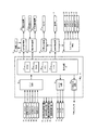
次に、弾球遊技機1の裏面の構造について図2を参照して説明する。図2は、弾球遊技機1を裏面から見た背面図である。
In addition, the specific game state according to the present invention is not limited to the above, and may be a state in which any one of the following
1. A variable winning device that can change between a first state that facilitates winning of a hit ball and a second state in which the hit ball cannot win or that is difficult to win, is changed to the first state continuously or intermittently for a predetermined time. 1. Control to A variable winning device that can change between a first state that makes it easy to win a hit ball and a second state that makes it difficult or difficult to win a ball, with the detection of a hit ball in a specific winning or passing area. 2. Control for setting to the first state continuously or intermittently for a predetermined time. 3. Control to discharge a predetermined number of prize balls directly regardless of the winning of the hit ball. 4. Control for adding a valuable number to a storage medium (card, receipt, etc.) having a valuable value Control for assigning points to a ball game machine that can be played based on the presence of a score Next, the structure of the back surface of the
図2に示すように、弾球遊技機1の裏面側では、表示部9を制御する表示制御用マイクロコンピュータが搭載された表示制御基板80を含む可変表示制御ユニット49、遊技制御用マイクロコンピュータ等が搭載された遊技制御基板(主基板)31が設置されている。また、球払出制御を行う払出制御用マイクロコンピュータ等が搭載された払出制御基板37が設置されている。なお、表示制御用マイクロコンピュータは、遊技盤6に設けられている表示部9、各種装飾LED、装飾ランプ25、枠側に設けられている天枠ランプ40、左枠ランプ41および右枠ランプ42を点灯制御するとともに、スピーカ27からの音発生を制御する。
As shown in FIG. 2, on the back side of the
表示制御用マイクロコンピュータは、表示制御基板80に搭載されている1つのマイクロコンピュータで実現されるが、遊技盤6に設けられている各種装飾LED、装飾ランプ25、枠側に設けられている天枠ランプ40、左枠ランプ41および右枠ランプ42を駆動するための駆動回路は、表示制御基板80と電気的に接続されているランプドライバ基板35に搭載されている。また、スピーカ27を駆動する駆動回路等は、表示制御基板80と電気的に接続されている音声出力基板70に搭載されている。
The display control microcomputer is realized by a single microcomputer mounted on the
さらに、DC30V、DC21V、DC12VおよびDC5Vを作成する電源回路が搭載された電源基板910やタッチセンサ基板91が設けられている。電源基板910は、大部分が主基板31と重なっているが、主基板31に重なることなく外部から視認可能に露出した露出部分がある。この露出部分には、弾球遊技機1における主基板31および各電気部品制御基板(表示制御基板80および払出制御基板37)や弾球遊技機1に設けられている各電気部品への電力供給を実行あるいは遮断するための電力供給許可手段としての電源スイッチと、主基板31および払出制御基板37に含まれる記憶内容保持手段(例えば、電力供給停止時にもその内容を保持可能なバックアップRAM)に記憶されたバックアップデータをクリアするための操作手段としてのクリアスイッチ65とが設けられている。さらに、露出部分における電源スイッチの内側(基板内部側)には、交換可能なヒューズが設けられている。
Further, a power supply substrate 910 and a
なお、電気部品制御基板には、電気部品制御用マイクロコンピュータを含む電気部品制御手段が搭載されている。電気部品制御手段は、遊技制御手段からの指令信号(制御信号)に従って弾球遊技機1に設けられている電気部品(遊技用装置:球払出装置97、表示部9、ランプやLEDなどの発光体等)を制御する。以下、主基板31を電気部品制御基板に含めて説明を行うことがある。その場合には、電気部品制御基板に搭載される電気部品制御手段は、遊技制御手段と、遊技制御手段からの指令信号に従って弾球遊技機1に設けられている電気部品を制御する手段とのそれぞれを指す。また、主基板31以外のマイクロコンピュータが搭載された基板をサブ基板ということがある。
An electrical component control means including an electrical component control microcomputer is mounted on the electrical component control board. The electrical component control means is an electrical component (game device: ball payout device 97,
弾球遊技機1の裏面において、上方には、各種情報を弾球遊技機1の外部に出力するための各端子を備えたターミナル基板160が設置されている。ターミナル基板160には、少なくとも、球切れ検出スイッチ167の出力を導入して外部出力するための球切れ用端子、賞球情報(賞球個数信号)を外部出力するための賞球用端子および球貸し情報(球貸し個数信号)を外部出力するための球貸し用端子が設けられている。また、中央付近には、主基板31からの各種情報を弾球遊技機1の外部に出力するための各端子を備えた情報端子基板(情報出力基板)34が設置されている。
On the back side of the
貯留タンク38に貯留された遊技球は誘導レール39を通り、カーブ樋を経て払出ケース40Aで覆われた球払出装置に至る。球払出装置の上部には、遊技媒体切れ検出手段としての球切れスイッチ187が設けられている。球切れスイッチ187が球切れを検出すると、球払出装置の払出動作が停止する。球切れスイッチ187は遊技球通路内の遊技球の有無を検出するスイッチであるが、貯留タンク38内の補給球の不足を検出する球切れ検出スイッチ167も誘導レール39における上流部分(貯留タンク38に近接する部分)に設けられている。球切れ検出スイッチ167が遊技球の不足を検知すると、弾球遊技機1が複数設置される遊技機設置島に設けられている補給機構から弾球遊技機1に対して遊技球の補給が行われる。
The game balls stored in the
入賞にもとづく景品としての遊技球や球貸し要求にもとづく遊技球が多数払い出されて打球供給皿3が満杯になると、遊技球は、余剰球通路を経て余剰球受皿4に導かれる。さらに遊技球が払い出されると、感知レバー(図示せず)が貯留状態検出手段としての満タンスイッチ(図示せず)を押圧して、貯留状態検出手段としての満タンスイッチがオンする。その状態では、球払出装置内の払出モータの回転が停止して球払出装置の動作が停止するとともに打球発射装置45の駆動も停止する。
When a large number of game balls as prizes based on winning a prize and game balls based on a ball lending request are paid out and the hitting
また、この実施の形態の弾球遊技機1は、遊技において遊技者の有利不利に関わる確率を示す複数の設定値のうちいずれか1つの設定値が設定され、以後、設定された設定値にもとづいて弾球遊技機1における遊技の進行を制御する。なお、遊技者の有利不利に関わる確率とは、例えば、上述した大当り遊技状態を発生させるか否かを判定する際に用いられる確率、上述した確変状態および/または時短状態に制御するか否かを判定する際に用いられる確率、確変状態および/または時短状態に制御するときに確変状態にて実行可能な特別図柄の可変表示回数(確変回数)および/または時短状態にて実行可能な特別図柄の可変表示回数(時短回数)を決定する際に用いられる確率、確変状態および/または時短状態を終了させるか否かを判定する際に用いられる確率、普通図柄表示器13にて当りとするか否かを判定する際に用いられる確率、後述する変動パターンを決定する際に用いられる確率、等のうち1つとしてもよいし、全部または任意の組み合わせとしてもよい。
弾球遊技機1の裏面に設けられた主基板31には、遊技者の有利不利に関わる確率の設定値を変更設定可能な設定スイッチ90が設けられている。設定スイッチ90は、設定キー91を差し込むことにより操作可能となる。なお、この実施の形態では、筐体形状の主基板ボックス内に主基板31が設置され、外部から直接主基板31に触れることができない。また、主基板ボックスの一部は、設定スイッチ90の外周に合致するよう刳り貫かれ、その刳貫部に設定スイッチ90が設置される。図3に設定スイッチ90および設定キー91の一例を示す。
Also, in the
The main board 31 provided on the back surface of the ball and
図3に示すように、設定スイッチ90は、「OFF」、「ON」、「+1」が付されており、設定キー91を差し込んでいない状態では、「OFF」の位置で保持されている。設定スイッチ90に設定キー91を差し込んで右に回し、「ON」の位置に回動すると、再び「OFF」の位置に回動するまで主基板31に操作信号を出力した状態となる。主基板31に搭載される遊技制御用マイクロコンピュータは、所定条件下で設定スイッチ90からの操作信号が入力されたことにもとづいて弾球遊技機1における遊技者の有利不利に関わる確率の設定値を変更設定可能な状態となる。設定スイッチ90が「ON」の位置にある状態でさらに設定キー91を右に回し、「+1」の位置に回動させると、主基板31に設定変更信号を出力する。主基板31に搭載される遊技制御用マイクロコンピュータは、設定変更信号が入力されたことにもとづいて確率の設定値を変更する処理を実行する。
As shown in FIG. 3, the setting
なお、この実施の形態では、遊技者の有利不利に関わる確率の設定値として「設定1」、「設定2」、「設定3」の3段階の設定値が予め設けられている。そして、設定スイッチ90によりいずれかの設定値に設定される。また、設定スイッチ90を「ON」としたときには初期設定として「設定1」の設定値に設定される。しかして、設定スイッチ90を「ON」に回動し、設定キー90を1回だけ「+1」の位置に回動した後、設定キー91を左に回して再び「ON」の位置に回動すると「設定2」の設定値に切り換えられる。弾球遊技機1の確率を「設定2」の設定値に設定する場合にはそのまま設定キー91を左に回して「OFF」の位置に回動し、操作キー91を抜けばよい。
In this embodiment, three setting values “setting 1”, “setting 2”, and “setting 3” are provided in advance as the setting values of the probabilities related to the player's advantage and disadvantage. Then, the setting
一方、弾球遊技機1の確率を「設定3」の設定値に設定する場合には、「設定2」の状態に切り換えた後、「OFF」の位置に回動せずに再び設定キー91を右に回して「+1」の位置に回動し、続けて設定キー91を左に回して「ON」の位置に回動することにより「設定3」の設定値に切り換えられ、そのまま設定キー91を左に回して「OFF」の位置に回動することにより「設定3」の設定値に設定される。なお、「設定3」の状態に切り換えた後、再び設定キー91を右に回して「+1」の位置に回動し、次いで設定キー91を左に回して「ON」の位置に回動することにより「設定1」の設定値に切り換えられる。このように、設定スイッチ90に設定キー91を差し込んで操作することにより、弾球遊技機1の設定値がカウントアップ形式(「設定1」から「設定3」に順次切り換えること)で切り換えられ、最大値(この場合には、「設定3」)に達したときに最小値(この場合には、「設定1」)に切り換えられるため、誤った設定値に切り換えた場合であっても所望の設定値に変更設定することができる。
On the other hand, when the probability of the
なお、この実施の形態では、設定スイッチ90によりカウントアップ形式で弾球遊技機1の設定値を切り換えるが、これに限られるものではない。例えば、初期設定として「設定3」の設定値に設定し、カウントダウン形式(「設定3」から「設定1」に順次切り換えること)で設定値を切り換えるようにしてもよい。この場合にも、「設定1」の設定値に切り換えた後、「OFF」の位置に回動せずにカウントダウンした場合には、「設定3」の設定値に切り換えるようにしてもよい。また、現在の設定値(「設定1」〜「設定3」のいずれであるか)を表示する表示器を設け、設定スイッチ90の操作に応じて設定値を表示するようにしてもよい。このように構成することにより、表示器を視認することで弾球遊技機1の設定値を把握でき、所望の設定値に確実に設定することが可能となる。
In this embodiment, the setting value of the bullet
図4は、主基板31における回路構成の一例を示すブロック図である。なお、図4には、払出制御基板37および表示制御基板80等も示されている。主基板31には、プログラムに従って弾球遊技機1を制御する基本回路(遊技制御用マイクロコンピュータ)53が搭載されている。基本回路53は、ゲーム制御用のプログラム等を記憶するROM54、ワークメモリとして使用される記憶手段としてのRAM55、プログラムに従って遊技の進行を制御するCPU56、及び表示制御基板80等に制御信号を送信するI/Oポート部57を含む。この実施の形態では、ROM54,RAM55はCPU56に内蔵されている。すなわち、CPU56は、1チップマイクロコンピュータである。なお、CPU56はROM54に格納されているプログラムに従って制御を実行するので、以下、CPU56が実行する(または、処理を行う)ということは、具体的には、CPU56がプログラムに従って制御を実行することである。このことは、主基板31以外の他の基板に搭載されているCPUについても同様である。また、この実施の形態で用いられる遊技制御用マイクロコンピュータとは、主基板31に搭載されるCPU56、ROM54、RAM55、I/Oポート部57、等の周辺回路(基本回路53)のことである。
FIG. 4 is a block diagram illustrating an example of a circuit configuration in the main board 31. 4 also shows the
なお、RAM55は、その一部または全部が電源基板910において作成されるバックアップ電源によってバックアップされている不揮発性記憶手段としてのバックアップRAMである。すなわち、弾球遊技機1に対する電力供給が停止しても、所定期間(バックアップ電源が電力供給不能になるまで)は、RAM55の一部または全部の内容は保存される。少なくとも、遊技状態すなわち遊技制御用マイクロコンピュータの制御状態に応じたデータ(特別図柄プロセスフラグ、状態データ、遊技者の有利不利に関わる確率の設定、等)は、バックアップRAMに保存される。遊技制御用マイクロコンピュータの制御状態に応じたデータとは、停電等が生じた後に復旧した場合に、そのデータにもとづいて制御状態を停電等の発生前に復旧させるために必要なデータである。
The
また、ゲートスイッチ61、始動口スイッチ62、カウントスイッチ63、V入賞スイッチ64、クリアスイッチ65、余剰球受皿4がいっぱいになったときに検出する満タンスイッチ(図示しない)、カウントスイッチ短絡信号(図示しない)、設定スイッチ90、からの信号を基本回路53に与えるスイッチ回路32、可変入賞装置15を開閉するソレノイド71、特別可変入賞装置20を開閉するソレノイド72、大入賞口内に設けられたシーソーを可動するソレノイド73、等を基本回路53からの指令に従って駆動するソレノイド回路33、電源投入時に基本回路53をリセットするためのシステムリセット回路(図示しない)、基本回路53から与えられるデータに従って、大当り遊技状態の発生を示す大当り情報、等の情報出力信号をホールコンピュータ等の外部装置に対して出力する情報出力回路34、も主基板31に搭載されている。
In addition, the
なお、ゲートスイッチ61、始動口スイッチ62、カウントスイッチ63、V入賞スイッチ64等のスイッチは、センサと称されるものでもよい。すなわち、遊技球を検出できる遊技媒体検出手段(この例では、遊技球検出手段)であれば、その名称を問わない。入賞検出を行う始動口スイッチ62、V入賞スイッチ64、カウントスイッチ63、の各スイッチは、入賞検出手段でもある。なお、入賞検出手段は、複数の入賞口に別個に入賞したそれぞれの遊技球をまとめて検出するものであってもよい。また、ゲートスイッチ63のような通過ゲートであっても、賞球の払い出しが行われるものであれば、通過ゲートへ遊技球が進入することが入賞になり、通過ゲートに設けられているスイッチ(例えば、ゲートスイッチ61)が入賞検出手段になる。さらに、この実施の形態では、V入賞領域に入賞した遊技球は対応するV入賞スイッチ64のみで検出されるので、大入賞口に入賞した遊技球数はV入賞スイッチ64による検出数とカウントスイッチ63による検出数との和になる。しかし、V入賞領域に入賞した遊技球がV入賞スイッチ64で検出されるとともにカウントスイッチ63でも検出されるようにしてもよい。その場合には、大入賞口に入賞した遊技球数は、カウントスイッチによる検出数に相当する。
Note that the switches such as the
主基板31に設けられた遊技制御用マイクロコンピュータ(CPU56及びROM54,RAM55等の周辺回路)は、現金、プリペイドカード、ICカード等が挿入されることによって球貸しを可能にする球貸ユニット50、遊技盤6に設けられた複数の入賞口にて遊技球の入賞を検出したことにより賞球払い出しを行う球払出装置44、を制御する払出制御基板37に払出制御信号を送信する。また、遊技制御用マイクロコンピュータは、打球操作ハンドル5を操作することにより打球発射装置45を駆動制御して遊技球を遊技領域7に向けて発射制御する発射制御基板36に発射制御信号を送信する。
A game control microcomputer (a peripheral circuit such as a
また、主基板31に設けられた遊技制御用マイクロコンピュータは、特図始動記憶表示器10、普図始動記憶表示器19の表示を制御するとともに、特別図柄表示器11に駆動信号を出力して特別図柄の可変表示制御、普通図柄表示器13に駆動信号を出力して普通図柄の可変表示制御、を実行する。
The game control microcomputer provided on the main board 31 controls the display of the special figure
さらに、遊技制御用マイクロコンピュータは表示制御基板80に演出制御コマンド(演出制御信号)を送信する。演出制御コマンドを受信することにより表示制御基板80に設けられた表示制御用マイクロコンピュータ(表示制御用CPU(図示しない)、RAM(図示しない)、ROM(図示しない)、I/Oポート部(図示しない)、等の周辺回路)は、表示部9の表示制御を行う。
Further, the game control microcomputer transmits an effect control command (effect control signal) to the
表示制御用CPUは、ROMに格納されたプログラムに従って動作し、主基板31から演出制御コマンドを受信すると、受信した演出制御コマンドに従って表示部9の表示制御を行う。具体的には、画像表示を行う表示制御機能及び高速描画機能を有するVDP(図示しない)により可変表示部の表示制御を行う。表示制御用CPUは、受信した演出制御コマンドに従ってキャラクタROM(図示しない)から必要なデータを読み出す。キャラクタROMは、表示部9に表示される画像の中でも使用頻度の高いキャラクタ画像データ、具体的には、人物、怪物、文字、図形または記号等を予め格納しておくためのものである。
The display control CPU operates according to a program stored in the ROM, and when receiving an effect control command from the main board 31, performs display control of the
そして、表示制御用CPUはキャラクタROMから読み出したデータをVDPに出力する。VDPは表示制御用CPUからデータが入力されたことにもとづいて動作する。この実施の形態では、表示部9の表示制御を行うVDP(図示しない)が表示制御基板80に搭載されている。また、VDPは、表示制御用CPUとは独立した二次元のアドレス空間を持ち、そこにVRAM(図示しない)をマッピングしている。
Then, the display control CPU outputs the data read from the character ROM to the VDP. The VDP operates based on data input from the display control CPU. In this embodiment, a VDP (not shown) that performs display control of the
VDPはキャラクタ画像データに従って表示部9に表示するための画像データを生成し、VDPはVRAMに展開する。VRAMはVDPによって生成された画像データを展開するためのフレームバッファメモリである。そして、表示部9に出力する。
The VDP generates image data to be displayed on the
また、この実施の形態では、表示制御基板80に設けられた表示制御用マイクロコンピュータが音声出力基板70にスピーカ27の駆動信号を出力し、スピーカ27の音声出力制御を行うともに、ランプドライバ基板35にランプ・LEDの駆動信号を出力し、弾球遊技機1に設けられたランプ・LEDの発光制御を行う。すなわち、表示制御基板80に搭載される表示制御用マイクロコンピュータは、主基板31から送信される表示部9の表示制御、ランプ・LEDの点灯制御、遊技音発生等の演出の制御に関する指令情報としての演出制御コマンド(制御信号)にもとづいて表示部9、スピーカ27、弾球遊技機1に設けられるランプ・LED等の発光体の制御を行う演出制御用マイクロコンピュータである。
In this embodiment, the display control microcomputer provided on the
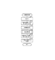
次に弾球遊技機1の動作について説明する。図5は、主基板31における遊技制御用マイクロコンピュータが実行するメイン処理を示すフローチャートである。弾球遊技機1に対して電源が投入されると、DC30V、DC21V、DC12VおよびDC5Vを作成する電源回路が搭載された電源基板910から電力供給開始を通知する電源断信号が主基板31に出力される。主基板31に搭載されるCPU56は、電源断信号が入力されるリセット端子の入力レベルがハイレベルになると、プログラムの内容が正当か否かを確認するための処理であるセキュリティチェック処理を実行した後、ステップS1以降のメイン処理を開始する。
なお、電源基板910から主基板31に出力される電源断信号は弾球遊技機1に供給される電圧が所定電圧(例えば、10V)以下になるまで出力した状態であり、弾球遊技機1に供給される電圧が所定電圧以下になったときに出力を停止する。すなわち、弾球遊技機1において正常な遊技が行われているときには、リセット端子の入力レベルは常にハイレベルであり、弾球遊技機1に供給される電圧が所定電圧以下になったときにリセット端子の入力レベルがローレベルとなる。
Next, the operation of the bullet
The power-off signal output from the power supply board 910 to the main board 31 is in a state in which it is output until the voltage supplied to the
メイン処理において、CPU56は、まず、必要な初期設定を行う。初期設定において、CPU56は、まず、割込禁止に設定する(ステップS1)。次に、割込モードを割込モード2に設定し(ステップS2)、スタックポインタにスタックポインタ指定アドレスを設定する(ステップS3)。そして、内蔵デバイスレジスタの初期化を行う(ステップS4)。
In the main process, the
次いで、内蔵デバイス(内蔵周辺回路)であるCTC(カウンタ/タイマ)およびPIO(パラレル入出力ポート)の初期化(ステップS5)を行った後、RAM55をアクセス可能状態に設定する(ステップS6)。
Next, after initialization (step S5) of CTC (counter / timer) and PIO (parallel input / output port) which are built-in devices (built-in peripheral circuits), the
この実施の形態で用いられるCPU56は、I/Oポート(PIO)およびタイマ/カウンタ回路(CTC)も内蔵している。また、CTCは、2本の外部クロック/タイマトリガ入力CLK/TRG2,3と2本のタイマ出力ZC/TO0,1を備えている。
The
この実施の形態で用いられているCPU56には、マスク可能な割込のモードとして以下の3種類のモードが用意されている。なお、マスク可能な割込が発生すると、CPU56は、自動的に割込禁止状態に設定するとともに、プログラムカウンタの内容をスタックにセーブする。
The
割込モード0:割込要求を行った内蔵デバイスがRST命令(1バイト)またはCALL命令(3バイト)をCPUの内部データバス上に送出する。よって、CPU56は、RST命令に対応したアドレスまたはCALL命令で指定されるアドレスの命令を実行する。リセット時に、CPU56は自動的に割込モード0になる。よって、割込モード1または割込モード2に設定したい場合には、初期設定において、割込モード1または割込モード2に設定するための処理を行う必要がある。
Interrupt mode 0: The built-in device that has issued the interrupt request sends an RST instruction (1 byte) or a CALL instruction (3 bytes) onto the internal data bus of the CPU. Therefore, the
割込モード1:割込が受け付けられると、常に0038(h)番地に飛ぶモードである。 Interrupt mode 1: In this mode, when an interrupt is accepted, the mode always jumps to address 0038 (h).
割込モード2:CPU56の特定レジスタ(Iレジスタ)の値(1バイト)と内蔵デバイスが出力する割込ベクタ(1バイト:最下位ビット0)から合成されるアドレスが、割込番地を示すモードである。すなわち、割込番地は、上位アドレスが特定レジスタの値とされ下位アドレスが割込ベクタとされた2バイトで示されるアドレスである。従って、任意の(飛び飛びではあるが)偶数番地に割込処理を設置することができる。各内蔵デバイスは割込要求を行うときに割込ベクタを送出する機能を有している。
Interrupt mode 2: A mode in which the address synthesized from the value (1 byte) of the specific register (I register) of the
よって、割込モード2に設定されると、各内蔵デバイスからの割込要求を容易に処理することが可能になり、また、プログラムにおける任意の位置に割込処理を設置することが可能になる。さらに、割込モード1とは異なり、割込発生要因毎のそれぞれの割込処理を用意しておくことも容易である。上述したように、この実施の形態では、初期設定のステップS2において、CPU56は割込モード2に設定される。
Therefore, when the interrupt
次いで、CPU56は、設定スイッチ90を操作したことにもとづく操作信号が入力されているかを1回だけ確認する(ステップS7)。その確認において、ONを検出した場合には、CPU56は後述する初期設定処理(ステップS13)を実行する。なお、初期設定処理(ステップS13)では、上述した設定スイッチ90の操作に応じて弾球遊技機1における確率の設定値を変更する設定変更処理も実行される。
Next, the
そして、CPU56は、入力ポート1を介して入力されるクリアスイッチ65の出力信号の状態を1回だけ確認する(ステップS8)。その確認においてオンを検出した場合には、CPU56は、設定スイッチ90がONになったか、すなわち、設定スイッチ90からの操作信号が入力されているかを確認し(ステップS12)、設定スイッチ90からの操作信号が入力されていれば初期設定処理を実行する(ステップS13)。なお、クリアスイッチ65がオンである場合(押下されている場合)には、ローレベルのクリアスイッチ信号が出力されている。なお、入力ポート1では、クリアスイッチ信号のオン状態はハイレベルである。また、例えば、遊技店員は、クリアスイッチ65をオン状態にしながら弾球遊技機1に対する電力供給を開始する(例えば電源スイッチをオンする)ことによって、容易に初期設定処理を実行させることができる。すなわち、RAMクリア等を行うことができる。
Then, the
ステップS8でクリアスイッチ65がオンの状態でない場合には、弾球遊技機1への電力供給が停止したときにバックアップRAM領域のデータ保護処理(例えばパリティデータの付加等の電源断検出時処理)が行われたか否か確認する(ステップS9)。弾球遊技機1への電力供給が停止したときにバックアップRAM領域のデータ保護処理が行われたとき、すなわち、後述する電源断検出時処理が実行されたときには、電源断フラグがセットされる。ステップS9では、電源断フラグがセットされているか否かを確認し、電源断フラグがセットされていればバックアップRAM領域のデータ保護処理が実行されたと判定し、電源断フラグがセットされていなければバックアップRAM領域のデータ保護処理が実行されていないと判定する。CPU56は、ステップS9で電源断フラグがセットされていなければ、設定スイッチ90からの操作信号が入力されているか確認し(ステップS12)、設定スイッチ90からの操作信号が入力されていれば初期設定処理(ステップS13)を実行する。
If the
なお、電源断検出時処理が実行されて電源断フラグがセットされた場合であっても、ノイズ等により電源断フラグがリセットされた状態となったときには、再び弾球遊技機1への電力供給が開始されたときに、CPU56はバックアップRAM領域のデータ保護処理が実行されていないと判定し、設定スイッチ90の確認および初期設定処理を実行する。このように、この実施の形態では、弾球遊技機1への電力供給の停止が生じた場合には、バックアップRAM領域のデータを保護するための処理(電源断検出時処理)が行われている。
Even when the power-off detection process is executed and the power-off flag is set, when the power-off flag is reset due to noise or the like, the power supply to the
この実施の形態では、バックアップRAM領域のデータを保護するための処理が行われていたか否かは、後述する電源断検出時処理において電源断フラグがセットされているか否かを確認することにより判定されるが、そのような確認の仕方は一例であって、例えば、バックアップRAM領域に保存されるバックアップ監視タイマの値が、バックアップRAM領域のデータ保護処理を実行したことに応じた値(例えば2)になっているか否かによって確認するようにしてもよい。 In this embodiment, whether or not the processing for protecting the data in the backup RAM area has been performed is determined by checking whether or not the power-off flag is set in the power-off detection processing described later. However, such a confirmation method is an example. For example, the value of the backup monitoring timer stored in the backup RAM area is a value (for example, 2) corresponding to the execution of the data protection processing of the backup RAM area. You may make it confirm by whether it is set to.
また、CPU56は、バックアップRAM領域のデータ保護処理を実行することにより、バックアップRAM領域に現在の遊技状態、確率設定(設定値)、等の情報をバックアップ(保存)する。そして、ステップS9で電源断フラグがセットされていることを確認したことにもとづいてバックアップRAM領域のデータ保護処理が実行された場合には、バックアップRAM領域に記憶される遊技状態、確率設定(設定値)等の情報が正常な情報であるかを判定する。具体的には、CPU56は、バックアップRAM領域のデータチェック(この例ではパリティチェック)を行う(ステップS10)。この実施の形態では、クリアデータ(00)をチェックサムデータエリアにセットし、チェックサム算出開始アドレスをポインタにセットする。また、チェックサムの対象となるデータ数に対応するチェックサム算出回数をセットする。そして、チェックサムデータエリアの内容とポインタが指すRAM領域の内容との排他的論理和を演算する。演算結果をチェックサムデータエリアにストアするとともに、ポインタの値を1増やし、チェックサム算出回数の値を1減算する。以上の処理が、チェックサム算出回数の値が0になるまで繰り返される。チェックサム算出回数の値が0になったら、CPU56は、チェックサムデータエリアの内容の各ビットの値を反転し、反転後のデータをチェックサムとする。
Further, the
後述する電源断検出時処理において、上記の処理と同様の処理によってチェックサムが算出され、チェックサムはバックアップRAM領域に保存されている。ステップS10では、算出したチェックサムと保存されているチェックサムとを比較する。不測の停電等により弾球遊技機1への電力供給が停止した後に復旧した場合には、バックアップRAM領域のデータは保存されているはずであるから、チェック結果(比較結果)は正常(一致)になる。チェック結果が正常でないということは、バックアップRAM領域のデータが、弾球遊技機1への電力供給が停止した時のデータとは異なっていることを意味する。そのような場合には、内部状態を弾球遊技機1への電力供給が停止した時の状態に戻すことができないので、電力供給の停止からの復旧時でない電源投入時に実行される処理と同様に設定スイッチ90からの操作信号が入力されているか確認し(ステップS12)、設定スイッチ90からの操作信号が入力されていれば初期設定処理(ステップS13)を実行する。
In a power-off detection process described later, a checksum is calculated by the same process as the above process, and the checksum is stored in the backup RAM area. In step S10, the calculated checksum is compared with the stored checksum. When the power supply to the
ステップS10でチェック結果が正常であれば、CPU56は、遊技制御用マイクロコンピュータの内部状態と表示制御用マイクロコンピュータ等の制御状態を電源断検出時の状態に戻すための復旧処理を行う(ステップS11)。
If the check result is normal in step S10, the
そして、ステップS14において、CPU56は、所定時間(例えば4ms)毎に定期的にタイマ割込がかかるようにCPU56に内蔵されているCTCのレジスタの設定を行なう。すなわち、初期値として例えば4msに相当する値が所定のレジスタ(時間定数レジスタ)に設定される。この実施の形態では、4ms毎に定期的にタイマ割込がかかるとする。
In step S14, the
ステップS1〜ステップS14の処理が完了すると、CPU56は、表示用乱数更新処理(ステップS16)および初期値用乱数更新処理(ステップS17)を繰り返し実行する。CPU56は、表示用乱数更新処理および初期値用乱数更新処理が実行されるときには割込禁止状態にして(ステップS15)、表示用乱数更新処理および初期値用乱数更新処理の実行が終了すると割込許可状態にする(ステップS18)。なお、表示用乱数とは、表示部9に表示される図柄を決定するための乱数であり、表示用乱数更新処理とは、表示用乱数を発生するためのカウンタのカウント値を更新する処理である。また、初期値用乱数更新処理とは、初期値用乱数を発生するためのカウンタのカウント値を更新する処理である。初期値用乱数とは、大当りとするか否かを決定するための乱数を発生するためのカウンタ(大当り判定用乱数発生カウンタ)等のカウント値の初期値を決定するための乱数である。後述する特別図柄プロセス処理(遊技制御用マイクロコンピュータが、弾球遊技機1に設けられている可変表示装置8、可変入賞装置15、球払出装置44等の遊技用の装置を、自身で制御する処理、または他のマイクロコンピュータに制御させるために指令信号を送信する処理)において、大当り判定用乱数発生カウンタのカウント値が1周すると、そのカウンタに初期値が設定される。
When the processing of step S1 to step S14 is completed, the
なお、表示用乱数更新処理および初期値用乱数更新処理が実行されるときに割込禁止状態にされるのは、表示用乱数更新処理および初期値用乱数更新処理が後述するタイマ割込処理でも実行されることから、タイマ割込処理における処理と競合してしまうのを避けるためである。すなわち、ステップS16,S17の処理中にタイマ割込が発生してタイマ割込処理中で表示用乱数や初期値用乱数を発生するためのカウンタのカウント値を更新してしまったのでは、カウント値の連続性が損なわれる場合がある。しかし、ステップS16,S17の処理中では割込禁止状態にしておけば、そのような不都合が生ずることはない。 Note that when the display random number update process and the initial value random number update process are executed, the interrupt disabled state is set even when the display random number update process and the initial value random number update process are performed by the timer interrupt process described later. This is to avoid conflict with the processing in the timer interrupt processing. That is, if a timer interrupt is generated during the processing of steps S16 and S17 and the count value of the counter for generating the display random number and the initial value random number is updated during the timer interrupt processing, The continuity of values may be impaired. However, such an inconvenience does not occur if the interrupt disabled state is set during the processing of steps S16 and S17.
図6は、図5に示すメイン処理のステップS11で実行される復旧処理を示すフローチャートである。復旧処理において、CPU56は、ROM54に格納されているバックアップ時設定テーブルの先頭アドレスをポインタに設定し(ステップS101)、バックアップ時設定テーブルの内容を順次作業領域(RAM55内の領域)に設定する(ステップS102)。作業領域はバックアップ電源によって電源バックアップされている。バックアップ時設定テーブルには、作業領域のうち初期化してもよい領域についての初期化データが設定されている。ステップS101およびステップS102の処理によって、作業領域のうち初期化してはならない部分については、保存されていた内容がそのまま残る。初期化してはならない部分とは、例えば、電源断検出以前の遊技状態を示すデータ(特別図柄プロセスフラグなど)や球払出装置44により払い出す賞球のうち未だ払い出されていない個数(未払出数)を示すデータが設定されている部分である。
FIG. 6 is a flowchart showing the recovery process executed in step S11 of the main process shown in FIG. In the restoration processing, the
また、CPU56は、ROM54に格納されているバックアップ時コマンド送信テーブルの先頭アドレスをポインタに設定し(ステップS103)、その内容に従ってサブ基板(払出制御基板37および表示制御基板80)に、電力供給が復旧した旨を示す制御信号が送信されるように制御する(ステップS104)。以上の処理により、弾球遊技機1を電源断検出以前の状態に復旧させることが可能となる。
Further, the
図7は、図5に示すメイン処理のステップS13で実行される初期設定処理を示すフローチャートである。初期設定処理において、CPU56は、まず、RAMクリア処理を行う(ステップS111)。なお、RAM55の全領域を初期化せず、所定のデータ(例えば大当り判定用乱数を生成するためのカウンタのカウント値のデータや確率設定(設定値)値等)をそのままにしてもよい。例えば、大当り判定用乱数を生成するためのカウンタのカウント値のデータをそのままにした場合には、不正な手段によって初期設定処理が実行される状態になったとしても、大当り判定用乱数を生成するためのカウンタのカウント値が大当り判定値に一致するタイミングを狙うことは困難である。また、ROM54に格納されている初期化時設定テーブルの先頭アドレスをポインタに設定し(ステップS112)、初期化時設定テーブルの内容を順次作業領域に設定する(ステップS113)。ステップS112およびステップS113の処理によって、例えば、普通図柄判定用乱数カウンタ、普通図柄判定用バッファ、特別図柄バッファ、総賞球数格納バッファ、特別図柄プロセスフラグ、賞球中フラグ、球切れフラグ、払出停止フラグなど制御状態に応じて選択的に処理を行うためのフラグに初期値が設定される。
FIG. 7 is a flowchart showing the initial setting process executed in step S13 of the main process shown in FIG. In the initial setting process, the
また、CPU56は、弾球遊技機1の確率の設定値を変更する設定変更処理を実行する(ステップS114)。設定変更処理では、上述した設定スイッチ90の操作に応じて弾球遊技機1の確率の設定値を変更する処理が実行される。そして、設定変更処理を実行すると、CPU56は、ROM54に格納されている初期化時コマンド送信テーブルの先頭アドレスをポインタに設定し(ステップS115)、その内容に従ってサブ基板を初期化するための初期化コマンドをサブ基板に送信する処理を実行する(ステップS116)。初期化コマンドとして、表示部9に表示される初期図柄を示すコマンド等がある。以上の処理により弾球遊技機1にて遊技を開始可能な状態になる。
Moreover, CPU56 performs the setting change process which changes the setting value of the probability of the ball game machine 1 (step S114). In the setting change process, a process of changing the set value of the probability of the
ここで、この実施の形態で用いられる乱数を説明する。図8は、この実施の形態で用いられる乱数を示す説明図である。各乱数は、以下のように使用される。
(1)大当り判定用乱数:大当りを発生させるか否か判定する
(2)特別図柄決定用乱数:特別図柄のはずれ図柄を決定する
(3)大当り図柄決定用乱数:特別図柄の大当り図柄を決定する
(4)変動パターン決定用乱数:特別図柄の変動パターンを決定する
(5)リーチ判定用乱数:大当りを発生させない場合にリーチとするか否かを判定する
(6)普通図柄当り判定用乱数:普通図柄にもとづく当りを発生させるか否か判定する
(7)大当り判定用乱数初期値決定用乱数:大当り判定用乱数の初期値を決定する
(8)普通図柄当り判定用乱数初期値決定用乱数:普通図柄当り判定用乱数の初期値を決定する
後述する2msタイマ割込処理におけるステップS23では、CPU56は、(1)の大当り判定用乱数、(3)の大当り図柄決定用乱数、(6)の普通図柄当り判定用乱数、を生成するためのカウンタのカウントアップ(1加算)を行う。また、後述する2msタイマ割込処理におけるステップS24およびメイン処理におけるステップS17では、(7)の大当り判定用乱数初期値決定用乱数、および、(8)の普通図柄当り判定用乱数初期値決定用乱数、を生成するためのカウンタのカウントアップ(1加算)を行い、後述する2msタイマ割込処理におけるステップS25およびメイン処理におけるステップS16では、(2)の特別図柄決定用乱数、(4)の変動パターン決定用乱数、(5)のリーチ判定用乱数、を生成するためのカウンタのカウントアップ(1加算)を行う。すなわち、(1)の大当り判定用乱数、(3)の大当り図柄決定用乱数、(6)の普通図柄当り判定用乱数、が判定用乱数であり、(2)の特別図柄決定用乱数、(4)の変動パターン決定用乱数、(5)のリーチ判定用乱数、が表示用乱数であり、(7)の大当り判定用乱数初期値決定用乱数、および、(8)の普通図柄当り判定用乱数初期値決定用乱数、が初期値用乱数である。
Here, the random numbers used in this embodiment will be described. FIG. 8 is an explanatory diagram showing random numbers used in this embodiment. Each random number is used as follows.
(1) Random number for jackpot determination: Determines whether or not to generate a jackpot (2) Random number for special symbol determination: Determines the special symbol detachment symbol (3) Random number for jackpot symbol determination: Determines the special symbol jackpot symbol (4) Random number for determining the variation pattern: Determine the variation pattern of the special symbol (5) Random number for reach determination: Determining whether to reach when the big hit is not generated (6) Random number for determining the regular symbol : Determine whether or not to generate a hit based on the normal symbol (7) Random number for determining the initial value of the big hit determination random number: Determine the initial value of the random number for determining the big hit (8) For determining the initial value of the random number for determining the normal symbol Random number: Determines the initial value of the random number for normal symbol determination In step S23 in the 2 ms timer interruption process described later, the
次に、遊技者の有利不利に関わる確率を示す複数の設定値を備える設定テーブルについて図9を参照して説明する。この実施の形態では、設定テーブルには、「設定1」〜「設定3」の設定値が備えられ、「設定1」〜「設定3」の各々には、大当り遊技状態を発生させるか否かを判定する際に用いられる確率、確変状態に制御するか否かを判定する際に用いられる確率、後述する変動パターンを決定する際に用いられる確率、が設定されている。 Next, a setting table including a plurality of setting values indicating probabilities related to the advantage and disadvantage of the player will be described with reference to FIG. In this embodiment, the setting table is provided with setting values “setting 1” to “setting 3”, and each of “setting 1” to “setting 3” determines whether or not to generate a big hit gaming state. The probability used when determining the probability, the probability used when determining whether or not to control the probability variation state, and the probability used when determining the variation pattern described later are set.
「設定1」においては、大当り判定値として、低確率時(通常遊技状態および時短状態)には、2個の大当り判定値が設定されるとともに、高確率時(確変状態)には、10個の大当り判定値が設定される。なお、大当り判定用乱数は、0〜999の範囲で更新され、「設定1」における低確率時の大当り確率(大当り遊技状態を発生させる旨の判定がなされる確率)は、500分の1であり、「設定1」における高確率時の大当り確率は、100分の1である。
In “
また、リーチ判定値として、低確率時には、3個のリーチ判定値が設定されるとともに、高確率時には、1個のリーチ判定値が設定される。なお、リーチ判定用乱数は、0〜27の範囲で更新され、「設定1」における低確率時のリーチ確率(大当り遊技状態を発生させる旨の判定がなされなかったときにリーチとする旨の判定がなされる確率)は、28分の3であり、「設定1」における高確率時のリーチ確率は、28分の1である。
Further, as reach determination values, three reach determination values are set when the probability is low, and one reach determination value is set when the probability is high. The reach determination random number is updated in the range of 0 to 27, and the reach probability at the time of low probability in “
さらに、確変判定値として8個の確変判定値が設定される。なお、確変判定値とは、上述した大当り図柄決定用乱数が確変判定値と一致したときに、特別図柄表示器11に特別表示結果(確変図柄)を導出表示して大当り遊技状態に制御し、大当り遊技状態が終了した後に確変状態に制御する確変大当りを発生させる旨の決定を行うための乱数である。また、大当り図柄決定用乱数は、0〜11の範囲で更新され、「設定1」における確変突入確率(大当り遊技状態を発生させる旨の判定がなされたときに、大当り遊技状態終了後に確変状態に制御する旨の判定がなされる確率)は、3分の2である。また、この実施の形態では、「設定1」に設定したときには、後述する変動パターンテーブルのうち変動パターンテーブル1を使用するテーブルとして設定する。
Further, eight probability variation determination values are set as probability variation determination values. The probability variation determination value means that when the above jackpot symbol determination random number coincides with the probability variation determination value, a special display result (probability variation symbol) is derived and displayed on the
「設定2」においては、大当り判定値として、低確率時には、3個の大当り判定値が設定されるとともに、高確率時には、15個の大当り判定値が設定される。すなわち、「設定2」における低確率時の大当り確率は、1000分の3であり、「設定2」における高確率時の大当り確率は、200分の3である。
In “
また、リーチ判定値として、低確率時には、2個のリーチ判定値が設定されるとともに、高確率時には、1個のリーチ判定値が設定される。すなわち、「設定2」における低確率時のリーチ確率は、14分1のであり、「設定2」における高確率時のリーチ確率は、28分の1である。
In addition, as reach determination values, two reach determination values are set when the probability is low, and one reach determination value is set when the probability is high. That is, the reach probability at the low probability in “
さらに、確変判定値として6個の確変判定値が設定される。すなわち、「設定2」における確変突入確率は、2分の1である。また、この実施の形態では、「設定2」に設定したときには、後述する変動パターンテーブルのうち変動パターンテーブル2を使用するテーブルとして設定する。
Further, six probability variation determination values are set as probability variation determination values. That is, the probability variation entry probability in “
「設定3」においては、大当り判定値として、低確率時には、4個の大当り判定値が設定されるとともに、高確率時には、20個の大当り判定値が設定される。すなわち、「設定3」における低確率時の大当り確率は、250分の1であり、「設定3」における高確率時の大当り確率は、50分の1である。
In “
また、リーチ判定値として、1個のリーチ判定値が設定される。すなわち、「設定3」におけるリーチ確率は、28分の1である。さらに、確変判定値として4個の確変判定値が設定される。すなわち、「設定3」における確変突入確率は、3分の1である。また、この実施の形態では、「設定3」に設定したときには、後述する変動パターンテーブルのうち変動パターンテーブル3を使用するテーブルとして設定する。
Further, one reach determination value is set as the reach determination value. That is, the reach probability in “
このように、この実施の形態では、「設定1」では、大当り確率が低く設定される一方、確変突入確率が高く設定され、「設定3」では、大当り確率が高く設定される一方、確変突入確率が低く設定される。また、「設定2」は、大当り確率および確変突入確率が「設定1」および「設定3」に設定される値の中間となっており、基本的な弾球遊技機の設定となっている。
As described above, in this embodiment, “setting 1” sets the big hit probability low, while setting “high probability probability”, and “setting 3” sets the big hit probability high, while Probability is set low. “Setting 2” is a basic setting of a ball game machine, in which the jackpot probability and the probability change entry probability are intermediate values set in “
なお、この実施の形態では、設定テーブルの設定値各々は、判定値の個数が異なるように構成されるが、これに限られるものではない。例えば、大当り判定値の個数を設定値毎に異ならせる一方、確変判定値の個数を変更せずに全ての設定値にて同一とすることにより、設定値に応じて大当り確率を異ならせる一方、全ての設定値にて同一の確変突入確率となるように設定テーブルを構成してもよい。 In this embodiment, each setting value in the setting table is configured so that the number of determination values is different, but the present invention is not limited to this. For example, while making the number of jackpot judgment values different for each set value, while making the same for all setting values without changing the number of probability variation judgment values, the jackpot probability is made different according to the set value, The setting table may be configured so that all the setting values have the same probability variation entry probability.
図10は、図7のステップS114で実行される設定変更処理を示すフローチャートである。上述したように、この実施の形態では、弾球遊技機1において、遊技者の有利不利に関わる確率を示す複数の設定値のうちいずれか1つの設定値が設定され、当該設定値にもとづいて遊技の進行を制御する。なお、複数の設定値として、この実施の形態では、図9に示す3つの設定値が予め設けられ、設定変更処理では、図9に示す「設定1」〜「設定3」の3つの設定値のうちいずれか1つの設定値に設定する。
FIG. 10 is a flowchart showing the setting change process executed in step S114 of FIG. As described above, in this embodiment, in the
設定変更処理において、CPU56は、まず、設定値に初期値としての「設定1」を設定する(ステップS121)。すなわち、設定値を変更するときには、弾球遊技機1の設定値を一旦、初期値に変更設定され、初期値としての「設定1」に設定された状態から設定値を変更していくこととなる。このように構成することにより、設定変更処理を実行する以前の弾球遊技機1における設定値を把握していない場合であっても所望の設定値に変更設定することができるため、所望の設定値とは異なる設定値に変更設定されてしまうことを防止できる。
In the setting change process, the
しかして、CPU56は、設定スイッチ90が「+1」の位置に回動されたことにもとづく設定変更信号が入力されているかを確認し(ステップS122)、設定変更信号が入力されていれば、現在の設定値に1加算した設定値に切り換える(ステップS123)。すなわち、現在の設定値が「設定1」であれば「設定2」に切り換え、現在の設定値が「設定2」であれば「設定3」に切り換える。また、上述したように、この実施の形態では、現在の設定値が上限値(MAX)である「設定3」である場合には設定値を最小値(MINIMUM)である「設定1」に切り換える。
Thus, the
次いで、CPU56は、設定スイッチ90が「ON」の位置に回動されたことにもとづいて設定スイッチ90からの設定変更信号がOFFになったら(ステップS124)、設定スイッチ90が「OFF」の位置に回動されたことにもとづいて設定スイッチ90からの操作信号がOFFになったか確認する(ステップS125)。ステップS125で設定スイッチ90からの操作信号がOFFになったら、現在の設定値をRAM55にストア(保存)する(ステップS126)。一方、ステップS125で設定スイッチ90からの操作信号がONであれば、再びステップS122に移行して設定変更処理を継続して実行する。
Next, when the setting change signal from the setting
なお、この実施の形態では、RAM55に設定値をストアする構成としているが、弾球遊技機1の設定状態を把握できるように保存すれば、保存するデータはこれに限られるものではない。例えば、ステップS126にて設定値に応じた各種確率(具体的には、大当り判定値等)を保存するように構成してもよい。
In this embodiment, the setting value is stored in the
主基板31に搭載されるCPU56は、ステップS126でストアした設定値にもとづいて弾球遊技機1における遊技の進行を制御する。具体的には、ステップS126でストアした設定値にもとづいてCPU56が後述する特別図柄プロセス処理を実行することにより弾球遊技機1における遊技の進行を制御する。
The
図11は、CPU56が実行するメイン処理にて2ms毎に実行されるタイマ割込処理を示すフローチャートである。タイマ割込が発生すると、CPU56は、割込処理の実行を禁止する(ステップS20)。割込処理の実行を禁止することにより2msタイマ割込処理の実行中に重複して2msタイマ割込処理が実行されることを防止できる。次いで、後述するバックアップ処理(ステップS35)でバックアップRAMに保存された遊技制御用マイクロコンピュータの制御状態に応じたデータが正常であるか確認する。具体的には、バックアップRAMに保存される遊技制御用マイクロコンピュータの制御状態に応じたデータのパリティチェックを行い(ステップS20a)、パリティチェックの結果が異常であれば、表示部9にてエラー状態が発生した旨を報知するエラー表示の実行を指示するエラー表示コマンドを表示制御基板80に送信する(ステップS20b)。そして、設定スイッチ90からの操作信号が入力されたことにもとづいて(ステップS20cにてYES)、上述した設定変更処理を実行する(ステップS20d)。
FIG. 11 is a flowchart showing a timer interrupt process executed every 2 ms in the main process executed by the
このように、ステップS20aでパリティチェックの結果が異常であると判定されたときには、ステップS20cで設定スイッチ90の操作信号の入力を監視するループ処理を実行して以降の処理の実行を停止させるエラー状態に制御し、ステップS20cで設定スイッチ90が操作されたことにもとづいて設定スイッチ90からの操作信号が主基板31に入力されたときにステップS20dで設定変更処理を実行した後にステップS21以降の処理を実行可能な状態、すなわち、エラー状態を解除した状態に制御する。換言すると、バックアップRAMに保存される遊技制御用マイクロコンピュータの制御状態に応じたデータが異常であれば、弾球遊技機1における遊技の進行を停止させるエラー状態に制御するとともに、弾球遊技機1の設定値を変更する処理を実行し、弾球遊技機1の設定値を変更する処理を手動操作で実行した後にエラー状態を解除させるため、不正等により設定値が変更された場合であっても当該不正により特定の利益を与えることを防止できる。
As described above, when it is determined in step S20a that the result of the parity check is abnormal, in step S20c, the loop process for monitoring the input of the operation signal of the setting
ステップS20dで設定変更処理を実行するとステップS21以降の処理を開始する。また、ステップS20aでバックアップRAMに保存される遊技制御用マイクロコンピュータの制御状態に応じたデータが正常であると判定されたときにはステップS20b〜ステップS20dの処理を実行することなくステップS21以降の処理を開始する。 When the setting change process is executed in step S20d, the process after step S21 is started. Further, when it is determined in step S20a that the data corresponding to the control state of the game control microcomputer stored in the backup RAM is normal, the processes in and after step S21 are performed without executing the processes in steps S20b to S20d. Start.
次いで、CPU56は、レジスタの退避処理(ステップS21)を行った後、ステップS22〜S37の遊技制御処理を実行する。遊技制御処理において、CPU56は、まず、スイッチ回路32を介して、ゲートスイッチ61、始動口スイッチ62、カウントスイッチ63、V入賞スイッチ64、クリアスイッチ65、等のスイッチの検出信号を入力し、それらの状態判定を行う(スイッチ処理:ステップS22)。
Next, the
次に、遊技制御に用いられる大当り判定用の乱数等の各判定用乱数を生成するための各カウンタのカウント値を更新する処理を行う(ステップS23:数値データ更新手段)。CPU56は、更に、初期値用乱数を生成するためのカウンタのカウント値を更新する処理(ステップS24)及び表示用乱数を生成するためのカウンタのカウント値を更新する処理を行う(ステップS25)。
Next, a process of updating the count value of each counter for generating each determination random number such as a big hit determination random number used for game control is performed (step S23: numerical data update means). The
更に、CPU56は、特別図柄プロセス処理を行う(ステップS26)。特別図柄プロセス制御では、遊技状態に応じて特別図柄表示器11、表示部9、特別可変入賞装置20、等を所定の順序で制御するための特別図柄プロセスフラグに従って該当する処理が選び出されて実行される。そして、特別図柄プロセスフラグの値は、遊技状態に応じて各処理中に更新される。
Further, the
また、普通図柄プロセス処理を行う(ステップS27)。普通図柄プロセス処理では、普通図柄表示器13の表示状態を所定の順序で制御するための普通図柄プロセスフラグに従って該当する処理が選び出されて実行される。そして、普通図柄プロセスフラグの値は、遊技状態に応じて各処理中に更新される。普通図柄プロセス処理を実行することにより普通図柄表示器13の表示制御および可変入賞装置15の開閉制御が実行される。
Further, normal symbol process processing is performed (step S27). In the normal symbol process, the corresponding process is selected and executed according to the normal symbol process flag for controlling the display state of the
次いで、CPU56は、飾り図柄9a〜9cに関する演出制御コマンドをRAM55の所定の領域に設定して表示制御基板80に送出する処理を行う(特別図柄コマンド制御処理:ステップS28)。
Next, the
更に、CPU56は、例えばホール管理用コンピュータに供給される大当り情報、始動情報、確率変動情報などのデータを出力する情報出力処理を行う(ステップS30)。
Further, the
また、CPU56は、始動口スイッチ62、カウントスイッチ63、V入賞スイッチ64、等の検出信号にもとづく賞球個数の設定などを行う賞球処理を実行する(ステップS31)。具体的には、始動口スイッチ62、カウントスイッチ63、V入賞スイッチ64、等の何れかがオンしたことにもとづく入賞検出に応じて、払出制御基板37に賞球個数を示す払出制御コマンドを出力する。払出制御基板37に搭載されている払出制御用CPUは、賞球個数を示す払出制御コマンドに応じて球払出装置44を駆動する。
Further, the
そして、CPU56は、始動記憶数の増減をチェックする記憶処理を実行する(ステップS32)。また、弾球遊技機1の制御状態を弾球遊技機1外部で確認できるようにするための試験信号を出力する処理である試験端子処理を実行する(ステップS33)。更に、所定の条件が成立したときにソレノイド回路33に駆動指令を行う(ステップS34)。可変入賞装置15、特別可変入賞装置20、を開状態または閉状態としたり、大入賞口内の遊技球通路を切り替えたりするために、ソレノイド回路33は、駆動指令に応じてソレノイド71〜73を駆動する。その後、遊技状態すなわち遊技制御用マイクロコンピュータの制御状態に応じたデータ(特別図柄プロセスフラグ、状態データ、遊技者の有利不利に関わる確率の設定、等)をバックアップRAMに保存するバックアップ処理を実行するとともに(ステップS35)、レジスタの内容を復帰させ(ステップS36)、割込許可状態に設定する(ステップS37)。
And CPU56 performs the memory | storage process which checks increase / decrease in the starting memory | storage number (step S32). Further, a test terminal process, which is a process of outputting a test signal for enabling the control state of the
以上の制御によって、この実施の形態では、遊技制御処理は2ms毎に起動されることになる。なお、この実施の形態では、タイマ割込処理で遊技制御処理が実行されているが、タイマ割込処理では例えば割込が発生したことを示すフラグのセットのみがなされ、遊技制御処理はメイン処理において実行されるようにしてもよい。 With the above control, in this embodiment, the game control process is started every 2 ms. In this embodiment, the game control process is executed by the timer interrupt process. However, in the timer interrupt process, for example, only a flag indicating that an interrupt has occurred is set, and the game control process is performed by the main process. May be executed.
なお、この実施の形態では、2msタイマ割込処理が実行される毎にバックアップRAMに遊技制御用マイクロコンピュータの制御状態に応じたデータを保存し、2msタイマ割込処理が実行される毎に遊技制御用マイクロコンピュータの制御状態に応じたデータが異常であるか確認するように構成しているが、これに限られるものではない。例えば、2msタイマ割込処理が予め定められた所定回数実行されたときにバックアップRAMに遊技制御用マイクロコンピュータの制御状態に応じたデータを保存し、次に2msタイマ割込処理が実行されたときに遊技制御用マイクロコンピュータの制御状態に応じたデータが異常であるか確認するようにしてもよい。 In this embodiment, every time the 2 ms timer interrupt process is executed, data corresponding to the control state of the game control microcomputer is stored in the backup RAM, and every time the 2 ms timer interrupt process is executed, the game is executed. Although it is configured to check whether the data corresponding to the control state of the control microcomputer is abnormal, the present invention is not limited to this. For example, when 2 ms timer interrupt processing is executed a predetermined number of times, data corresponding to the control state of the game control microcomputer is stored in the backup RAM, and then 2 ms timer interrupt processing is executed In addition, it may be confirmed whether the data corresponding to the control state of the game control microcomputer is abnormal.
図12は、図11のステップS35で実行されるバックアップ処理を示すフローチャートである。バックアップ処理において、CPU56は、パリティチェックデータを作成する(ステップS201〜ステップS210)。すなわち、まず、クリアデータ(00)をチェックサムデータエリアにセットし(ステップS201)、チェックサム算出開始アドレスをポインタにセットする(ステップS202)。また、チェックサム算出回数をセットする(ステップS203)。
FIG. 12 is a flowchart showing the backup process executed in step S35 of FIG. In the backup process, the
次いで、チェックサムデータエリアの内容とポインタがさすRAM領域の内容との排他的論理和を演算する(ステップS204)。演算結果をチェックサムデータエリアにストアするとともに(ステップS205)、ポインタの値を1増やし(ステップS206)、チェックサム算出回数の値を1減算する(ステップS207)。そして、ステップS204〜ステップS207の処理を、チェックサム算出回数の値が0になるまで繰り返す(ステップS208)。 Next, an exclusive OR of the contents of the checksum data area and the contents of the RAM area pointed to by the pointer is calculated (step S204). The calculation result is stored in the checksum data area (step S205), the pointer value is incremented by 1 (step S206), and the value of the checksum calculation count is decremented by 1 (step S207). Then, the processing from step S204 to step S207 is repeated until the value of the checksum calculation count becomes 0 (step S208).
チェックサム算出回数の値が0になったら、CPU56は、チェックサムデータエリアの内容の各ビット値を反転する(ステップS209)。そして、反転後のデータをチェックサムデータエリアにストアする(ステップS210)。このデータが図11のステップS20aでチェックされるパリティデータとなる。
When the value of the checksum calculation count becomes 0, the
以上の処理によって、バックアップ処理が実行されると演算結果を反転した値がバックアップRAMのチェックサムデータエリアへストア(保存)される。 When the backup process is executed by the above process, a value obtained by inverting the operation result is stored (saved) in the checksum data area of the backup RAM.
図13は、弾球遊技機1に供給される電力の供給が停止するときに実行される電源断検出時処理のフローチャートである。電源断検出時処理は、弾球遊技機1に供給される電圧が所定の電圧(例えば、80V)以下になったことにもとづいて他の処理に優先して実行される。
FIG. 13 is a flowchart of power-off detection processing that is executed when the supply of power supplied to the
電源断検出時処理において、CPU56は、バックアップ処理を実行する(ステップS221)。バックアップ処理は、図12に示すものと同様である。また、バックアップ処理が実行されると演算結果を反転した値がバックアップRAMのチェックサムデータエリアへストア(保存)され、弾球遊技機1への電力供給を再開したときに図5のステップS10でチェックされるパリティデータとなる。次いで、RAMアクセス禁止レジスタにアクセス禁止値を設定する(ステップS222)。以後、RAM55へのアクセスができなくなる。
In the power-off detection process, the
さらに、CPU56は、ROM54に格納されているポートクリア設定テーブルの先頭アドレスをポインタにセットする(ステップS223)。ポートクリア設定テーブルにおいて、先頭アドレスには処理数(クリアすべき出力ポートの数)が設定され、次いで、出力ポートのアドレスおよび出力値データ(クリアデータ:出力ポートの各ビットのオフ状態の値)が、処理数分の出力ポートについて順次設定されている。
Further, the
CPU56は、ポインタが指すアドレスのデータ(すなわち処理数)をロードする(ステップS224)。また、ポインタの値を1増やし(ステップS225)、ポインタが指すアドレスのデータ(すなわち出力ポートのアドレス)をロードする(ステップS226)。さらに、ポインタの値を1増やし(ステップS227)、ポインタが指すアドレスのデータ(すなわち出力値データ)をロードする(ステップS228)。そして、出力値データを出力ポートに出力する(ステップS229)。その後、処理数を1減らし(ステップS230)、処理数が0でなければ(ステップS231にてNO)、ステップS225に戻る。処理数が0であれば(ステップS231にてYES)、すなわち、クリアすべき出力ポートを全てクリアしたら、タイマ割込を停止するとともに(ステップS232)、電源断フラグをセットし(ステップS233)、ループ処理に入る。なお、ステップS233でセットされる電源断フラグは、図5のステップS9で確認され、電源断フラグがセットされていることにもとづいて設定スイッチ90の操作検出および初期設定処理(ステップS13)が実行される。
The
ループ処理では、電源断信号がOFF状態になったか否か監視する(ステップS234)。電源断信号がOFF状態になった場合には復帰アドレスとして、電源投入時実行アドレス(ステップS1のアドレス)を設定してリターン命令を実行する(ステップS235)。上述したように、電源基板910から主基板31に出力される電源断信号は、弾球遊技機1に供給される電圧が所定電圧(例えば、10V)以下になったときにOFFになる。すなわち、弾球遊技機1に供給される電圧が所定電圧以下になったときにステップS235の処理を実行する。
In the loop processing, it is monitored whether or not the power-off signal has been turned off (step S234). When the power-off signal is turned off, the return address is set as the return address and the return address is executed (step S235). As described above, the power-off signal output from the power supply board 910 to the main board 31 is turned off when the voltage supplied to the
以上の処理によって、弾球遊技機1への電力の供給が停止する場合には、電源断検出時処理が実行されて、電源断検出時処理が実行されたことを示すデータ(電源断フラグおよびチェックサム)がバックアップRAMへストア(保存)される。また、RAMアクセスが禁止状態にされ、出力ポートがクリアされる。さらに、遊技制御処理を実行するためのタイマ割込が禁止状態に設定される。
When the supply of power to the
また、電源断信号がOFF状態になった場合には、図5のステップS1に戻る。その場合、電源断検出時処理が実行されたことを示すデータがバックアップRAMにストアされているので、バックアップRAMにストアされているデータが正常であれば復旧処理(ステップS11)が実行される。よって、電源断検出時処理を実行した後に弾球遊技機1への電力供給が再開されたときには、遊技の進行を制御する状態に戻る。従って、瞬間的に電圧が低下する電源瞬断等が生じても、遊技制御処理が停止してしまうようなことはなく、自動的に遊技制御処理が実行される。
If the power-off signal is turned off, the process returns to step S1 in FIG. In this case, since data indicating that the process at the time of power-off detection is executed is stored in the backup RAM, if the data stored in the backup RAM is normal, the recovery process (step S11) is executed. Therefore, when the power supply to the
図14は、主基板31に搭載されるCPU56が実行する特別図柄プロセス処理(ステップS26)のプログラムの一例を示すフローチャートである。上述したように、特別図柄プロセス処理では遊技状態に応じて特別図柄表示器11、表示部9、特別可変入賞装置20、等を所定の順序で制御する処理が実行される。CPU56は、特別図柄プロセス処理を行う際に、遊技盤6に設けられている始動入賞口14に遊技球が入賞したことを検出するための始動口スイッチ62がオンしていたら、すなわち遊技球が始動入賞口14に入賞する始動入賞が発生していたら(ステップS311)、始動口スイッチ通過処理(ステップS312)を行った後に、内部状態に応じて、ステップS300〜S307のうちのいずれかの処理を行う。
FIG. 14 is a flowchart illustrating an example of a special symbol process (step S26) program executed by the
特別図柄通常処理(ステップS300):特別図柄の可変表示を開始できる状態になるのを待つ。CPU56は、特別図柄の可変表示が開始できる状態になると、始動記憶バッファに記憶される数値データの記憶数(始動記憶数)を確認する。始動記憶バッファに記憶される数値データの記憶数は始動記憶カウンタのカウント値により確認できる。そして、始動記憶カウンタのカウント値が0でなければ、特別図柄の可変表示の結果、当りとするか否か(特定表示結果とするか否か)を決定する。具体的には、始動記憶バッファのうち1番目の領域に保存される大当り判定用乱数と設定値に応じた大当り判定値とが一致するか否かを判定し、一致するときに当りとする旨の判定を行う。なお、始動記憶バッファは、1番目の領域から4番目の領域までの4つの領域を有し、大当り判定用乱数を1番目の領域から順に格納する。そして、特別図柄の可変表示を開始するときに1番目の領域に格納している大当り判定用乱数を読み出すとともに、n番目の領域に保存される大当り判定用乱数をn−1番目の領域にシフトする(例えば、2番目の領域に保存される大当り判定用乱数を1番目の領域にシフトする)。当りとする場合には大当りフラグをセットする。そして、内部状態(特別図柄プロセスフラグ)をステップS301に移行するように更新する。
Special symbol normal processing (step S300): Waits until the variable symbol variable display can be started. When the
特別図柄停止図柄設定処理(ステップS301):可変表示後の特別図柄の停止図柄を決定する。そして、内部状態(特別図柄プロセスフラグ)をステップS302に移行するように更新する。なお、特別図柄の停止図柄は当りとなるときには「0」〜「11」の識別情報のうちいずれかに決定される。具体的には、大当り図柄決定用乱数にもとづいて特別図柄の大当り図柄(当りとなるときの特別図柄の停止図柄)を決定する。また、上述したように大当り図柄決定用乱数と確変判定値とが一致するか否か確認し、一致する場合に大当り図柄が確変図柄となる旨の判定をし、大当り遊技状態終了後に確変状態に制御する一方、大当り図柄決定用乱数と確変判定値とが一致するか否か確認し、一致しない場合に大当り図柄が確変図柄とは異なる非確変図柄になる旨の判定をし、大当り遊技状態終了後に通常遊技状態に制御する。すなわち、特別図柄の大当り図柄を決定することにより大当り遊技状態終了後に特別図柄表示器11にて可変表示される特別図柄の表示結果が大当り図柄(特定表示結果)となる確率が高い確変状態と通常遊技状態とのいずれの遊技状態に制御するかを決定している。また、特別図柄の停止図柄をはずれとするときには、特別図柄の停止図柄を「0」〜「11」以外に決定する。この実施の形態では、特別図柄の停止図柄をはずれとするときには、特別図柄の停止図柄として「−」に決定する。
Special symbol stop symbol setting process (step S301): A special symbol stop symbol after variable display is determined. Then, the internal state (special symbol process flag) is updated so as to shift to step S302. The stop symbol of the special symbol is determined as one of the identification information “0” to “11” when winning. Specifically, the big hit symbol of the special symbol (the special symbol stop symbol at the time of winning) is determined based on the big hit symbol determining random number. In addition, as described above, it is confirmed whether or not the big hit symbol determination random number and the probability variation determination value match, and if they match, it is determined that the big hit symbol becomes a probability variation symbol, and the probability variation state is entered after the jackpot gaming state ends. On the other hand, it is checked whether the jackpot symbol determination random number and the probability variation judgment value match, and if they do not match, it is determined that the jackpot symbol becomes a non-probability variation symbol different from the probability variation symbol, and the jackpot gaming state ends. Later, the normal gaming state is controlled. That is, by determining the jackpot symbol of the special symbol, the probability variation state in which there is a high probability that the display result of the special symbol variably displayed on the
変動パターン設定処理(ステップS302):特別図柄の可変表示の変動パターン(可変表示データ)を、始動入賞発生時に抽出した変動パターン決定用乱数の値に応じて予め定められた複数種類の変動パターン(可変表示データ)の中から1つの変動パターンを選択する。変動パターンには変動態様と、該変動態様を実行する時間(変動時間)と、を特定する情報が含まれている。また、決定された変動パターンにもとづいて、特別図柄表示器11にて特別図柄の可変表示を行って表示結果を導出するまでの可変表示時間(変動時間)を特別図柄プロセスタイマにセットした後、特別図柄プロセスタイマをスタートさせる。このとき、特別図柄表示器11にて特別図柄の可変表示を開始するとともに、表示制御基板80に対して、特別図柄の停止図柄を指令する情報(特別図柄指定コマンド)と、変動時間を含む変動態様(変動パターン)を指令する情報(変動パターンコマンド)と、が送信される。そして、内部状態(特別図柄プロセスフラグ)をステップS303に移行するように更新する。
Fluctuation pattern setting process (step S302): A variation pattern (variable display data) of variable display of a special symbol is selected from a plurality of types of variation patterns determined in advance according to the value of a variation pattern determination random number extracted at the time of start winning. One variation pattern is selected from (variable display data). The variation pattern includes information for identifying the variation mode and the time (variation time) for executing the variation mode. Moreover, after setting the variable display time (variation time) until the display result is derived by performing variable display of the special symbol on the
特別図柄変動処理(ステップS303):変動パターン設定処理で選択された変動パターンの変動時間が経過(ステップS302でセットされた特別図柄プロセスタイマがタイムアウト)すると、内部状態(特別図柄プロセスフラグ)をステップS304に移行するように更新する。 Special symbol variation process (step S303): When the variation time of the variation pattern selected in the variation pattern setting process elapses (the special symbol process timer set in step S302 times out), the internal state (special symbol process flag) is stepped. Update to shift to S304.
特別図柄停止処理(ステップS304):特別図柄表示器11において可変表示される特別図柄を停止表示させるとともに、表示部9において可変表示される飾り図柄9a〜9cが停止されるように制御する。具体的には、特別図柄の変動表示を停止させることを示す演出制御コマンド(特別図柄停止コマンド)が送信される状態に設定する。そして、大当りフラグがセットされている場合には、内部状態(特別図柄プロセスフラグ)をステップS305に移行するように更新する。そうでない場合には、内部状態をステップS300に移行するように更新する。
Special symbol stop process (step S304): The special symbol variably displayed on the
大入賞口開放前処理(ステップS305):大入賞口を開放する制御を開始する。具体的には、カウンタやフラグを初期化するとともに、ソレノイド72を駆動して特別可変入賞装置20を開状態とすることで大入賞口を開放する。また、プロセスタイマによって大入賞口開放中処理の実行時間を設定し、内部状態(特別図柄プロセスフラグ)をステップS306に移行するように更新する。
Preliminary winning opening opening process (step S305): Control for opening the large winning opening is started. Specifically, the counter and flag are initialized, and the
大入賞口開放中処理(ステップS306):大当り遊技状態中のラウンド表示の演出制御コマンドを表示制御基板80に送出する制御や大入賞口の閉成条件の成立を確認する処理等を行う。最後の大入賞口の閉成条件が成立したら、大入賞口内に設けられたV入賞スイッチ64の通過の有無を監視して、大当り遊技状態継続条件の成立を確認する処理を行う。大当り遊技状態継続の条件が成立し、且つ、まだ残りラウンドがある場合には、内部状態をステップS305に移行するように更新する。また、所定の有効時間内に大当り遊技状態継続条件が成立しなかった場合、または、全てのラウンドを終えた場合には、内部状態をステップS307に移行するように更新する。
Processing during opening of the big prize opening (step S306): Control for sending the effect control command for round display during the big hit gaming state to the
大当り終了処理(ステップS307):大当り遊技状態が終了したことを遊技者に報知する表示制御を演出制御手段に行わせるための制御を行う。そして、内部状態をステップS300に移行するように更新する。 Big hit end processing (step S307): Control for causing the effect control means to perform display control for notifying the player that the big hit gaming state has ended. Then, the internal state is updated so as to shift to step S300.
図15は、特別図柄プロセス処理における特別図柄通常処理(ステップS300)を示すフローチャートである。特別図柄通常処理において、CPU56は、特別図柄の変動表示を開始することができる状態(例えば特別図柄プロセスフラグの値がステップS300を示す値となっている場合)であれば(ステップS51)、始動記憶数の値を確認する(ステップS52)。具体的には、始動記憶カウンタのカウント値を確認する。なお、特別図柄プロセスフラグの値がステップS300を示す値となっている場合とは、特別図柄表示器11において特別図柄の変動表示がなされていず、かつ、特別図柄表示器11に大当り図柄が導出表示されたことにもとづく大当り遊技状態が実行中でもない場合である。
FIG. 15 is a flowchart showing the special symbol normal process (step S300) in the special symbol process. In the special symbol normal process, the
ステップS52にて始動記憶数が0でなければ、RAM55の始動記憶バッファにおける始動記憶数=1に対応する保存領域に格納されている各乱数値を読み出してRAM55の乱数バッファ領域に格納するとともに(ステップS53)、始動記憶数の値を1減らし(始動記憶カウンタのカウント値を1減算し)、かつ、各保存領域の内容をシフトする(ステップS54)。すなわち、RAM55の始動記憶バッファにおいて始動記憶数=n(n=2,3,4)に対応する保存領域に格納されている各乱数値を、始動記憶数=n−1に対応する保存領域に格納する。よって、各始動記憶数に対応するそれぞれの保存領域に格納されている各乱数値が抽出された順番は、常に、始動記憶数=1,2,3,4の順番と一致するようになっている。すなわち、この例では、可変表示の開始条件が成立する毎に、各保存領域の内容をシフトする構成としているので、各乱数値が抽出された順番を特定することができる。
If the starting storage number is not 0 in step S52, each random number value stored in the storage area corresponding to the starting storage number = 1 in the starting storage buffer of the
次いで、CPU56は、乱数格納バッファから大当り判定用乱数を読み出し(ステップS55)、大当り判定処理サブルーチンを実行する(ステップS56)。大当りとすることに決定した場合には(ステップS57)、CPU56は、大当りフラグをセットする(ステップS58)。そして、特別図柄プロセスフラグの値を特別図柄停止図柄設定処理(ステップS301)に対応した値に更新する(ステップS59)。
Next, the
図16は、大当り判定処理(ステップS56)を示すフローチャートである。大当り判定処理において、CPU56は、まず、設定スイッチ90の操作にもとづいてRAM55に記憶された弾球遊技機1の設定値を読み出す(ステップS251)。そして、読み出した弾球遊技機1の設定値が正常な値であるか否か、すなわち、この実施の形態では、設定値が「設定1」〜「設定3」のいずれかに設定されるため、弾球遊技機1の設定値が「設定1」〜「設定3」のいずれかであるかを確認する(ステップS252)。
FIG. 16 is a flowchart showing the big hit determination process (step S56). In the big hit determination process, the
なお、この実施の形態では、ステップS252で弾球遊技機1の設定値が正常な値であるか否かを確認するが、弾球遊技機1の確率設定に関わる異常を検出するものであれば、これに限られるものではない。例えば、大当り確率等が正常な範囲内(この実施の形態では、低確率状態(通常状態、時短状態等)において大当り確率が500分の2から500分の4の範囲内、高確率状態(確変状態)において大当り確率が500分の10から500分の20の範囲内)であるかを確認するようにしてもよいし、大当り判定値等の個数が正常な範囲内(この実施の形態では、低確率状態において大当り判定値の個数が2〜4の範囲内、高確率状態において大当り判定値の個数が10〜20の範囲内)であるかを確認するようにしてもよい。
In this embodiment, it is confirmed whether or not the set value of the
ステップS252で弾球遊技機1の設定値が正常な値であると判定された場合には、ステップS256以降の処理を行う。一方、ステップS252で弾球遊技機1の設定値が正常な値ではないと判定された場合には、表示部9にてエラー状態が発生した旨を報知するエラー表示の実行を指示するエラー表示コマンドを表示制御基板80に送信する(ステップS253)。そして、設定スイッチ90からの操作信号が入力されたことにもとづいて(ステップS254にてYES)、上述した設定変更処理を実行する(ステップS255)。
If it is determined in step S252 that the set value of the
以上の処理によりCPU56は、ステップS251で読み出した弾球遊技機1の設定値またはステップS255で再設定されてRAM55に記憶された弾球遊技機1の設定値に応じた大当り判定テーブルを使用することに決定する。次いで、CPU56は、現在の遊技状態が確変状態であることを示す確変状態フラグがセットされているか確認する(ステップS257)。すなわち、そのときの遊技機の遊技状態が確変状態であるか否か判定する。確変状態フラグがセットされていれば、すなわち、確変状態であれば、ステップS256で決定された大当り判定テーブルのうち高確率時のテーブルを使用することに決定する(ステップS258)。確変状態でなければ、ステップS256で決定された大当り判定テーブルのうち低確率時のテーブルを使用することに決定する(ステップS259)。
With the above processing, the
そして、抽出されている大当り判定用乱数の値に合致する値がステップS258またはステップS259で決定した大当り判定テーブル中にあるか判定し(ステップS260)、合致する値があれば(ステップS261)、大当りとすることにし(ステップS262)、合致する値がなければ大当りとしないことに決定する(ステップS263)。 Then, it is determined whether there is a value that matches the extracted jackpot determination random number in the jackpot determination table determined in step S258 or step S259 (step S260), and if there is a match value (step S261), The jackpot is determined (step S262), and if there is no matching value, it is determined that the jackpot is not set (step S263).
このように、ステップS252で弾球遊技機1の設定値が異常であると判定されたときには、ステップS254で設定スイッチ90の操作信号の入力を監視するループ処理を実行して以降の処理の実行を停止させるエラー状態に制御し、ステップS254で設定スイッチ90が操作されたことにもとづいて設定スイッチ90からの操作信号が主基板31に入力されたときにステップS255で設定変更処理を実行した後にステップS256以降の処理を実行可能な状態、すなわち、エラー状態を解除した状態に制御する。換言すると、RAM55に保存される弾球遊技機1の設定値が異常であれば、弾球遊技機1における遊技の進行を停止させるエラー状態に制御するとともに、弾球遊技機1の設定値を変更する処理を実行し、弾球遊技機1の設定値を変更する処理を手動操作で実行した後にエラー状態を解除させるため、不正等により設定値が変更された場合であっても当該不正により特定の利益を与えることを防止できる。
As described above, when it is determined in step S252 that the set value of the
図17は、この実施の形態で用いられる変動パターンの一例を示す説明図である。図17において、「EXT」とは、「MODE」と「EXT」との2バイト構成の演出制御コマンドにおける2バイト目のEXTデータを示す。この実施の形態では、表示制御基板80に送信する演出制御コマンドは、主基板31に搭載されるROM54に格納される「MODE」と「EXT」とからなる2バイト構成のデータであり、1バイト目はMODE(コマンドの分類)を表し、2バイト目はEXT(コマンドの種類)を表す。なお、そのようなコマンド形態は一例であって他のコマンド形態を用いてもよい。例えば、1バイトや3バイト以上で構成される制御コマンドを用いてもよい。
FIG. 17 is an explanatory diagram showing an example of a variation pattern used in this embodiment. In FIG. 17, “EXT” indicates EXT data of the second byte in the effect control command having a two-byte configuration of “MODE” and “EXT”. In this embodiment, the effect control command transmitted to the
また、「時間」は特別図柄(および飾り図柄9a〜9c)の変動時間(識別情報の可変表示時間)を示す。この例では、特別図柄の各変動パターンは、大当りとするか否か、表示部9にて飾り図柄9a〜9cをリーチとするか否か、表示部9にて飾り図柄9a〜9cをリーチとする場合のリーチ表示態様、など各種の演出態様の違いに応じて複数種類用意されている。
“Time” indicates a variation time (variable display time of identification information) of the special symbol (and the decorative symbols 9a to 9c). In this example, each variation pattern of the special symbol is a big hit, whether the
なお、「通常変動」とは、飾り図柄9a〜9cのリーチ表示態様を伴わない変動パターンである。「ノーマルリーチ」とは、飾り図柄9a〜9cのリーチ表示態様を伴うが表示結果(停止図柄)が大当りを生じさせるものとならない(非特定表示結果)変動パターンである。「リーチA」は、「ノーマルリーチ」とは異なる飾り図柄9a〜9cのリーチ表示態様を持つ変動パターンである。また、飾り図柄9a〜9cのリーチ表示態様が異なるとは、飾り図柄9a〜9cがリーチ表示態様となった後のリーチ変動時間において異なった態様の変動態様(速度や回転方向等)やキャラクタ等が現れることをいう。例えば、「ノーマルリーチ」では単に1種類の変動態様によって飾り図柄9a〜9cのリーチ表示態様が実現されるのに対して、「リーチA」では、変動速度や変動方向が異なる複数の変動態様を含む飾り図柄9a〜9cのリーチ表示態様が実現される。 The “normal variation” is a variation pattern that does not accompany the reach display mode of the decorative symbols 9a to 9c. “Normal reach” is a variation pattern that involves the reach display mode of the decorative symbols 9a to 9c, but the display result (stop symbol) does not cause a big hit (non-specific display result). “Reach A” is a variation pattern having a reach display mode of decorative symbols 9a to 9c different from “normal reach”. Further, the reach display modes of the decorative symbols 9a to 9c are different from each other. The variation modes (speed, rotational direction, etc.) of the different modes in the reach variation time after the decorative symbols 9a to 9c are changed to the reach display mode, characters, etc. Means that appears. For example, in “normal reach”, the reach display mode of the decorative symbols 9a to 9c is realized by only one type of variation mode, whereas “reach A” includes a plurality of variation modes having different variation speeds and variation directions. The reach display mode of the decorative symbols 9a to 9c is realized.
また、「リーチB」は、「ノーマルリーチ」および「リーチA」とは異なる飾り図柄9a〜9cのリーチ表示態様を持つ変動パターンであり、また、「リーチC」は、「ノーマルリーチ」、「リーチA」および「リーチB」とは異なる飾り図柄9a〜9cのリーチ表示態様を持つ変動パターンである。また、「短縮変動」とは、「通常変動」と同様に飾り図柄9a〜9cのリーチ表示態様を伴わない変動パターンであるが、変動時間が短い(この実施の形態では、1秒)変動パターンである。なお、「短縮変動」は、確変状態および時短状態にて大当り遊技状態を発生させないと判定され、かつ、リーチ表示態様を伴わないと判定されたときに実行される変動パターンである。そのため、確変状態および時短状態では、通常遊技状態に比べて特別図柄表示器11における特別図柄の変動時間が短くなる。
“Reach B” is a variation pattern having a reach display mode of decorative symbols 9a to 9c different from “Normal reach” and “Reach A”, and “Reach C” is “Normal reach” and “Reach A”. ”And“ Reach B ”are variation patterns having a reach display mode of decorative symbols 9a to 9c. The “shortening variation” is a variation pattern that does not accompany the reach display mode of the decorative symbols 9a to 9c as in the “normal variation”, but has a short variation time (1 second in this embodiment). It is. The “shortening variation” is a variation pattern that is executed when it is determined that the big hit gaming state is not generated in the probability variation state and the short time state, and it is determined that the reach display mode is not involved. Therefore, the variation time of the special symbol in the special
また、この実施の形態では、高確率時(確変状態)でも低確率時(非確変状態=通常遊技状態および時短状態)でも変動パターン1〜10の変動パターンが用いられるが、高確率時には変動パターン2〜9のそれぞれの変動時間を短くするようにしてもよい。また、高確率時に用いられる変動パターン群(使用されうる複数の変動パターン)と低確率時に用いられる変動パターン群とを別にしてもよい。
In this embodiment, the
図18は、遊技者の有利不利に関わる確率を示す複数の設定値に応じて設定される変動パターンテーブルを示す説明図である。この実施の形態では、設定値毎に変動パターン決定用乱数の判定値の振分けが異なる変動パターンテーブルが設けられている。具体的には、「設定1」に対応して「変動パターンテーブル1」が、「設定2」に対応して「変動パターンテーブル2」が、「設定3」に対応して「変動パターンテーブル3」が設けられている。しかして、上述したように、設定スイッチ90を操作して、弾球遊技機1の設定値を変更することにより、設定値に応じた変動パターンテーブルを使用する変動パターンテーブルとしてRAM55の使用変動パターンテーブル種類設定領域に設定する。
FIG. 18 is an explanatory diagram showing a variation pattern table set in accordance with a plurality of set values indicating probabilities related to the player's advantages and disadvantages. In this embodiment, there is provided a variation pattern table in which distribution of determination values of variation pattern determination random numbers is different for each set value. Specifically, “variation pattern table 1” corresponding to “setting 1”, “variation pattern table 2” corresponding to “setting 2”, and “variation pattern table 3” corresponding to “setting 3”. Is provided. Thus, as described above, by operating the setting
そして、上述した変動パターン設定処理において使用変動パターンテーブル種類設定領域に設定された種類の変動パターンテーブルと、変動パターン決定用乱数と、を比較し、種類設定領域に設定された種類の変動パターンテーブルに予め定められた複数種類の変動パターンのうち比較される変動パターン決定用乱数と同一の値を示す判定値が設定された1つの変動パターンを選択する。なお、それぞれの設定値毎に設けられた各変動パターンテーブルには、変動パターン決定用乱数と比較される判定値が、各変動パターンに対応して振り分けられた状態で設定される。図18には、各変動パターンテーブルにて、各変動パターンに対応して振り分けられた判定値の数が表されている。 Then, the variation pattern table of the type set in the used variation pattern table type setting area in the variation pattern setting process described above is compared with the random number for determining the variation pattern, and the variation pattern table of the type set in the type setting area One variation pattern in which a determination value indicating the same value as the variation pattern determining random number to be compared is selected from among a plurality of predetermined variation patterns. In each variation pattern table provided for each set value, a determination value to be compared with a variation pattern determination random number is set in a state of being distributed corresponding to each variation pattern. FIG. 18 shows the number of determination values assigned to each variation pattern in each variation pattern table.
なお、設定値毎に変動パターンテーブルを異ならせることなく、設定値に関わらず同一の変動パターンテーブルを用いるようにしてもよいし、複数の設定値のうち複数の設定値にて同一の変動パターンテーブルを用いるようにしてもよい。例えば、「設定1」および「設定2」に設定されたときには同一の第1変動パターンテーブルを用い、「設定3」に設定されたときには第1変動パターンテーブルとは異なる第2変動パターンテーブルを用いるように構成してもよい。 The same variation pattern table may be used regardless of the setting value without changing the variation pattern table for each setting value, or the same variation pattern may be used for a plurality of setting values among a plurality of setting values. A table may be used. For example, when “Setting 1” and “Setting 2” are set, the same first variation pattern table is used, and when “Setting 3” is set, a second variation pattern table different from the first variation pattern table is used. You may comprise as follows.
以上、本実施形態では、弾球遊技機1にてバックアップRAM領域に現在の遊技状態、確率設定(設定値)、等の情報をバックアップ(保存)し、バックアップRAM領域に保存されるデータが異常であれば遊技の進行を停止するエラー状態に制御する。そして、エラー状態では、手動操作で弾球遊技機1の確率設定(設定値)を変更する処理を実行した後にエラー状態を解除させるため、不正等により設定値が変更された場合であっても当該不正により特定の利益を与えることを防止できる。
As described above, in the present embodiment, information such as the current gaming state, probability setting (setting value), etc. is backed up (saved) in the backup RAM area in the
また、エラー状態では、設定スイッチ90を手動で操作することにより遊技者の有利不利に関わる確率として、大当り遊技状態を発生させるか否かを判定する際に用いられる確率、上述した確変状態および/または時短状態に制御するか否かを判定する際に用いられる確率、等を設定し、その後、エラー状態が解除されるため、遊技者の公平性を図ることができる。
Further, in the error state, the probability used when determining whether or not to generate the big hit gaming state as the probability related to the advantage / disadvantage of the player by manually operating the setting
また、弾球遊技機1への電力の供給が開始されたときにバックアップRAM領域に遊技状態、確率設定(設定値)、等の情報がバックアップされていることを示す電源断フラグがセットされていれば、当該情報が異常であるか否か確認し、異常であれば手動操作で弾球遊技機1の確率設定(設定値)を変更する処理を実行するまで遊技の進行を停止させるため、遊技者の有利不利に関わる確率の設定値が自動的に設定されて遊技が開始されてしまうことを防止でき、遊技者の公平性を図ることができる。また、弾球遊技機1への電力の供給が開始されたときに電源断フラグがセットされていなければ、バックアップRAM領域にバックアップされる情報が異常であるか確認しないため、処理負担を軽減できる。
In addition, when power supply to the
また、設定スイッチ90を操作して遊技者の有利不利に関わる確率としての設定値を変更する場合には、一旦RAM55をクリアした後に変更した設定値を設定する。この実施の形態では、弾球遊技機1への電力の供給が開始されたときに電源断フラグがセットされているか否かおよびバックアップされている情報が異常であるか否かを確認する以前に設定スイッチ90からの操作信号が入力されているか否かを確認するため、設定値を変更する場合に不必要な処理を行うことがない。
Further, when the setting value as the probability related to the player's advantage or disadvantage is changed by operating the setting
なお、この実施の形態では、RAM55のバックアップRAM領域に遊技状態、確率設定(設定値)、等の情報をバックアップ(保存)するが、弾球遊技機1への電力供給が停止しても所定期間は情報を保存するものであれば保存する手段はこれに限られるものではない。例えば、主基板31にRAM55とは別にEPROM(Erasable Programmable Read Only Memory)を備える構成とし、EPROMにバックアップするようにしてもよい。さらに、この実施の形態では、弾球遊技機1への電力供給が停止したときにRAM55に電源断フラグを記憶するように構成されるが、弾球遊技機1への電力供給が停止しても所定期間は電源断フラグを記憶可能なものであれば記憶手段はこれに限られるものではない。例えば、主基板31にRAM55とは別個に設けられたEPROMに電源断フラグを記憶するようにしてもよい。
In this embodiment, information such as gaming state, probability setting (setting value), etc. is backed up (saved) in the backup RAM area of the
また、この実施の形態では、設定キー91を設定スイッチ90に差し込み、設定キー91を回動させることにより弾球遊技機1の設定値を変更可能となる例について示したが、弾球遊技機1における遊技者の有利不利に関わる確率の設定値を変更する手段はこれに限られるものではない。例えば、主基板31に弾球遊技機1の設定値を変更設定可能なロータリースイッチを設け、解除キーを操作したことにもとづいてロータリースイッチを回動可能な状態にした後、ロータリースイッチを回動させて弾球遊技機1の設定値を変更するようにしてもよいし、主基板31に弾球遊技機1の設定値を変更設定可能なディップスイッチを設け、解除キーを操作したときにディップスイッチを操作可能な状態にして、ディップスイッチを操作することにより弾球遊技機1の設定値を変更するようにしてもよい。なお、弾球遊技機1の設定値を変更する設定変更手段(例えば、ロータリースイッチ、ディップスイッチ、等)と、設定変更手段の操作を規制する規制手段と、を別個に設けるように構成してもよく、規制解除手段(解除キー等)により規制手段による設定変更手段の規制が解除したときに設定変更手段により弾球遊技機1の設定値を変更可能となるように構成してもよい。また、設定変更手段を主基板とは別に設け、設定変更手段と主基板とを信号線により接続し、設定変更手段が操作されたときに信号線から操作信号を主基板に出力するようにしてもよい。
In this embodiment, the setting
また、本発明は、スロットマシン(回動式遊技機)においても適用可能である。なお、スロットマシンにて遊技者の有利不利に関わる確率の設定値を変更する場合には、主基板と別個に設けられるとともに主基板と信号線にて接続された設定変更手段(例えば、設定変更装置)を操作することにより主基板に変更後の設定値に関する情報を出力する。また、設定変更手段は、通常、操作を受け付けない規制状態とされ、規制解除手段(例えば、解除キー)を操作する(例えば、設定変更装置の錠に解除キーを差し込んで回動する)ことにより操作を受け付ける規制解除状態とされる。そして、規制解除状態にて、設定変更手段を操作する(例えば、設定変更装置の設定変更ボタンを操作する)ことで設定値を切り換え、所望の設定値に切り換えたときに設定決定手段(例えば、操作レバー)を操作することで設定変更手段から主基板に変更後の設定値に関する情報を出力し、入力された設定値に関する情報にもとづいて主基板に搭載される遊技制御用マイクロコンピュータによりスロットマシンの設定値を設定する(例えば、RAMに記憶する)ように構成される。この場合には、設定変更手段を操作するとき(例えば、設定変更装置の設定変更ボタンを操作するとき)に表示器(例えば、払出数を表示する表示器、残りの遊技媒体数を示すクレジット表示器、等)に切り換えた設定値を表示するようにしてもよい。このように構成することにより表示器に表示される設定値を見ながら設定変更装置を操作でき、所望の設定値に確実に変更できる。 The present invention can also be applied to slot machines (rotating game machines). When changing the setting value of the probability related to the player's advantage and disadvantage in the slot machine, a setting changing means (for example, setting change) provided separately from the main board and connected to the main board by a signal line. By operating the apparatus, information regarding the changed set value is output to the main board. In addition, the setting change unit is normally in a restricted state in which no operation is accepted, and by operating a restriction release unit (for example, a release key) (for example, by inserting the release key into the lock of the setting change device and rotating). The restriction is released to accept the operation. Then, in the restriction release state, the setting change means is operated (for example, the setting change button of the setting change device is operated), and the setting value is switched. By operating the operation lever), the setting change means outputs information on the changed set value to the main board, and the slot machine is operated by the game control microcomputer mounted on the main board based on the inputted setting value information. Are set (for example, stored in a RAM). In this case, when operating the setting change means (for example, when operating the setting change button of the setting change device), a display (for example, a display for displaying the number of payouts, a credit display indicating the number of remaining game media) The set value may be displayed on the display. With this configuration, the setting change device can be operated while viewing the set value displayed on the display, and can be reliably changed to a desired set value.
また、この実施の形態では、弾球遊技機に適用した例を示したが、本発明は、スロットマシン(回動式遊技機)、パロット等にも適用可能である。 Further, in this embodiment, an example is shown in which the present invention is applied to a ball game machine, but the present invention can also be applied to a slot machine (rotating game machine), a parrot, and the like.
また、この実施の形態では、主基板31に設定スイッチ90を設置する構成としているが、主基板31に設置しなくてもよい。例えば、主基板31とは異なる位置に設定スイッチを設け、設定スイッチと主基板とを繋ぐ信号線を設けることで、設定スイッチからの信号を主基板に入力するように構成してもよい。
In this embodiment, the setting
1 弾球遊技機
8 可変表示装置
9 表示部
11 特別図柄表示器
14 始動入賞口
15 可変入賞装置
31 主基板
37 払出制御基板
53 基本回路
55 RAM
56 CPU
70 音声出力基板
35 ランプドライバ基板
80 表示制御基板
90 設定スイッチ
91 設定キー
DESCRIPTION OF
56 CPU
70
Claims (4)
設定操作手段の操作に基づいて、前記表示結果が特定表示結果となる確率が異なる複数種類の設定値のうちからいずれかの設定値を設定する設定値設定手段と、
該設定値設定手段により設定された設定値を示す確率設定情報を含む遊技の制御を行うためのデータを記憶する記憶手段と、
弾球遊技機への電力供給が停止しても前記記憶手段に記憶されている前記遊技の制御を行うためのデータを保持する保持手段と、
弾球遊技機への電力供給が開始されたときに、前記遊技の制御を行うためのデータが電力供給停止前のデータと一致するか否かの判定を行う記憶内容判定手段と、
該記憶内容判定手段により前記記憶手段に記憶されている前記遊技の制御を行うためのデータが電力供給停止前のデータと一致しないと判定された場合に、遊技の進行を停止させる第1遊技進行停止手段と、
前記可変表示が行われる毎に前記記憶手段に記憶されている前記遊技の制御を行うためのデータのうち前記確率設定情報を読み出し、該読み出した前記確率設定情報の示す前記設定値が前記設定値設定手段により設定可能な設定値の範囲内である場合に前記読み出した確率設定情報を適正であると判定し、前記設定可能な設定値の範囲内でない場合に前記読み出した確率設定情報を適正ではないと判定する設定値判定手段と、
該設定値判定手段により前記読み出した確率設定情報を適正であると判定したときに、該読み出した確率設定情報の示す設定値に応じた確率で前記表示結果を前記特定表示結果とするか否か判定する事前判定手段と、
前記設定値判定手段により前記読み出した確率設定情報を適正ではないと判定された場合に、遊技の進行を停止させる第2遊技進行停止手段と、
前記第1遊技進行停止手段により前記遊技の進行を停止させた状態においても前記第2遊技進行停止手段により前記遊技の進行を停止させた状態においても、前記設定操作手段の操作に基づいて前記設定値設定手段により前記設定値が新たに設定されたことを条件に、前記遊技の進行を再開させる遊技進行再開手段と、を備えたことを特徴とする弾球遊技機。 Provided with a variable display unit for variably displaying a plurality of types of identification information each identifiable based on the establishment of a predetermined start condition and deriving and displaying the display result, and the display result of the variable display unit is specified in advance In a ball game machine that controls to a specific gaming state advantageous to the player when the display result is obtained,
A setting value setting means for setting any setting value from a plurality of types of setting values having different probabilities that the display result is a specific display result based on an operation of the setting operation means ;
Storage means for storing data for controlling the game, including a probability setting information indicating setting value set by the setting value setting means,
Holding means for holding data for controlling the game stored in the storage means even when power supply to the ball game machine is stopped;
A storage content determination means for determining whether or not the data for controlling the game coincides with the data before stopping the power supply when power supply to the ball game machine is started;
The first game progress that stops the progress of the game when it is determined by the stored content determination means that the data for controlling the game stored in the storage means does not match the data before the power supply is stopped Stop means;
The probability setting information is read out of the data for controlling the game stored in the storage unit each time the variable display is performed, and the setting value indicated by the read probability setting information is the setting value. It is determined that the read probability setting information is appropriate when it is within the set value range that can be set by the setting means, and the read probability setting information is not appropriate when it is not within the set value range that can be set. Setting value determination means for determining that there is no
Whether or not to set the display result as the specific display result with a probability corresponding to the set value indicated by the read probability setting information when the set value determining means determines that the read probability setting information is appropriate Pre-determination means for determining;
Second game progress stopping means for stopping the progress of the game when the set value determining means determines that the read probability setting information is not appropriate;
The setting based on the operation of the setting operation means in the state where the progress of the game is stopped by the first game progress stopping means and in the state where the progress of the game is stopped by the second game progress stopping means. A bullet ball game machine comprising: game progress resuming means for resuming the progress of the game on condition that the set value is newly set by the value setting means .
設定操作手段の操作に基づいて、前記特定表示結果となる場合に前記特別表示結果となる確率が異なる複数種類の設定値のうちからいずれかの設定値を設定する設定値設定手段と、
該設定値設定手段により設定された設定値を示す特別表示結果確率設定情報を含む遊技の制御を行うためのデータを記憶する記憶手段と、
弾球遊技機への電力供給が停止しても前記記憶手段に記憶されている前記遊技の制御を行うためのデータを保持する保持手段と、
弾球遊技機への電力供給が開始されたときに、前記遊技の制御を行うためのデータが電力供給停止前のデータと一致するか否かの判定を行う記憶内容判定手段と、
該記憶内容判定手段により前記記憶手段に記憶されている前記遊技の制御を行うためのデータが電力供給停止前のデータと一致しないと判定された場合に、遊技の進行を停止させる第1遊技進行停止手段と、
前記可変表示が行われる毎に前記記憶手段に記憶されている前記遊技の制御を行うためのデータのうち前記特別表示結果確率設定情報を読み出し、該読み出した前記特別表示結果確率設定情報の示す前記設定値が前記設定値設定手段により設定可能な設定値の範囲内である場合に前記読み出した特別表示結果確率設定情報を適正であると判定し、前記設定可能な設定値の範囲内でない場合に前記読み出した特別表示結果確率設定情報を適正ではないと判定する設定値判定手段と、
該設定値判定手段により前記読み出した特別表示結果確率設定情報を適正であると判定したときに、前記表示結果を前記特定表示結果とするか否か判定する事前判定手段と、
該事前判定手段により前記表示結果を前記特定表示結果とする旨の判定がなされたときに、前記読み出した特別表示結果確率設定情報の示す設定値に応じた確率で前記表示結果を前記特定表示結果のうち前記特別表示結果にするか否かを判定する表示結果判定手段と、
前記設定値判定手段により前記読み出した特別表示結果確率設定情報を適正ではないと判定された場合に、遊技の進行を停止させる第2遊技進行停止手段と、
前記第1遊技進行停止手段により前記遊技の進行を停止させた状態においても前記第2遊技進行停止手段により前記遊技の進行を停止させた状態においても、前記設定操作手段の操作に基づいて前記設定値設定手段により前記設定値が新たに設定されたことを条件に、前記遊技の進行を再開させる遊技進行再開手段と、を備えたことを特徴とする弾球遊技機。 Provided with a variable display unit for variably displaying a plurality of types of identification information each identifiable based on the establishment of a predetermined start condition and deriving and displaying the display result, and the display result of the variable display unit is specified in advance When the display result is reached, the specific game state is controlled to be advantageous to the player, and the display result of the variable display section is based on the fact that the display result of the specific display result is a special display result determined in advance. A ball game machine that controls a special game state that is more advantageous to the player than a normal state different from the specific game state after the state ends,
On the basis of the operation of the setting operation unit, a setting value setting means the special display results Do that probability when the said specific display result set one setting value from among the different types of setting values,
Storage means for storing data for controlling the game, including special display result probability setting information indicating a setting value set by the setting value setting means,
Holding means for holding data for controlling the game stored in the storage means even when power supply to the ball game machine is stopped;
A storage content determination means for determining whether or not the data for controlling the game coincides with the data before stopping the power supply when power supply to the ball game machine is started;
The first game progress that stops the progress of the game when it is determined by the stored content determination means that the data for controlling the game stored in the storage means does not match the data before the power supply is stopped Stop means;
The special display result probability setting information is read out from the data for controlling the game stored in the storage means each time the variable display is performed, and the read-out special display result probability setting information indicates the When the set value is within the range of the set value that can be set by the set value setting means, the read special display result probability setting information is determined to be appropriate, and when the set value is not within the range of the set value that can be set Setting value determination means for determining that the read special display result probability setting information is not appropriate;
Prior determination means for determining whether or not the display result is the specific display result when it is determined that the read special display result probability setting information is appropriate by the setting value determination means;
When it is determined by the prior determination means that the display result is the specific display result, the display result is displayed with the probability according to the set value indicated by the read special display result probability setting information. Display result determination means for determining whether or not to make the special display result of
Second game progress stopping means for stopping the progress of a game when the set value determining means determines that the read special display result probability setting information is not appropriate;
The setting based on the operation of the setting operation means in the state where the progress of the game is stopped by the first game progress stopping means and in the state where the progress of the game is stopped by the second game progress stopping means. A bullet ball game machine comprising: game progress resuming means for resuming the progress of the game on condition that the set value is newly set by the value setting means .
弾球遊技機への電力供給が開始されたときに、弾球遊技機への電力供給が停止したことが前記状態記憶手段に記憶されているか否か判定する電源断判定手段と、をさらに備え、
前記第1遊技進行停止手段は、前記電源断判定手段により弾球遊技機への電力供給が停止したことが前記状態記憶手段に記憶されていないときにも遊技の進行を停止させることを特徴とする請求項1又は請求項2に記載の弾球遊技機。 State storage means capable of storing over a predetermined period that the power supply to the ball and ball game machine has been stopped when the power supply to the ball and ball game machine is stopped;
A power-off determining unit that determines whether or not the state storage unit stores that the power supply to the ball and ball game machine has been stopped when the power supply to the ball and ball game machine is started. ,
The first game progress stopping means stops the progress of the game even when the state storage means does not store that the power supply to the bullet ball game machine has been stopped by the power-off determining means. The bullet ball game machine according to claim 1 or 2 .
前記設定値設定手段は、前記操作判定手段により前記設定操作手段が操作されたと判定されたことにもとづいて前記設定値を設定するための設定処理を実行することを特徴とする請求項1から請求項3のいずれかに記載の弾球遊技機。 When power supply to a pinball game machine is started, before the data for controlling the game by the storage content determining means for determining whether or not to match the data before power outage, the An operation determining means for determining whether or not the setting operation means has been operated ;
The set value setting means, claim 1, characterized in that executing the setting processing for setting the set value based on said setting operation unit is judged to be operated by said operation determination means The bullet ball game machine according to claim 3 .
Priority Applications (1)
| Application Number | Priority Date | Filing Date | Title |
|---|---|---|---|
| JP2005178223A JP4859397B2 (en) | 2005-06-17 | 2005-06-17 | Bullet ball machine |
Applications Claiming Priority (1)
| Application Number | Priority Date | Filing Date | Title |
|---|---|---|---|
| JP2005178223A JP4859397B2 (en) | 2005-06-17 | 2005-06-17 | Bullet ball machine |
Related Child Applications (1)
| Application Number | Title | Priority Date | Filing Date |
|---|---|---|---|
| JP2011161825A Division JP5220169B2 (en) | 2011-07-25 | 2011-07-25 | Bullet ball machine |
Publications (2)
| Publication Number | Publication Date |
|---|---|
| JP2006346276A JP2006346276A (en) | 2006-12-28 |
| JP4859397B2 true JP4859397B2 (en) | 2012-01-25 |
Family
ID=37642721
Family Applications (1)
| Application Number | Title | Priority Date | Filing Date |
|---|---|---|---|
| JP2005178223A Expired - Fee Related JP4859397B2 (en) | 2005-06-17 | 2005-06-17 | Bullet ball machine |
Country Status (1)
| Country | Link |
|---|---|
| JP (1) | JP4859397B2 (en) |
Cited By (11)
| Publication number | Priority date | Publication date | Assignee | Title |
|---|---|---|---|---|
| JP2019076264A (en) * | 2017-10-22 | 2019-05-23 | 京楽産業.株式会社 | Game machine |
| JP2019136259A (en) * | 2018-02-09 | 2019-08-22 | 株式会社三共 | Game machine |
| JP2020058443A (en) * | 2018-10-05 | 2020-04-16 | 株式会社三共 | Game machine |
| JP2020058442A (en) * | 2018-10-05 | 2020-04-16 | 株式会社三共 | Game machine |
| JP2020058444A (en) * | 2018-10-05 | 2020-04-16 | 株式会社三共 | Game machine |
| JP2020120779A (en) * | 2019-01-29 | 2020-08-13 | 株式会社ソフイア | Game machine |
| JP2021006325A (en) * | 2020-10-26 | 2021-01-21 | 株式会社三共 | Game machine |
| JP2021006324A (en) * | 2020-10-26 | 2021-01-21 | 株式会社三共 | Game machine |
| JP2021006323A (en) * | 2020-10-26 | 2021-01-21 | 株式会社三共 | Game machine |
| JP2021006326A (en) * | 2020-10-26 | 2021-01-21 | 株式会社三共 | Game machine |
| JP2021184854A (en) * | 2018-10-05 | 2021-12-09 | 株式会社三共 | Game machine |
Families Citing this family (102)
| Publication number | Priority date | Publication date | Assignee | Title |
|---|---|---|---|---|
| JP6655904B2 (en) * | 2015-07-24 | 2020-03-04 | 株式会社三共 | Gaming machine |
| JP6623336B2 (en) * | 2015-11-30 | 2019-12-25 | 株式会社高尾 | Gaming machine |
| JP6616695B2 (en) * | 2016-01-22 | 2019-12-04 | 株式会社三共 | Game machine |
| JP6809910B2 (en) * | 2016-01-22 | 2021-01-06 | 株式会社三共 | Game machine |
| JP2019000559A (en) * | 2017-06-19 | 2019-01-10 | サミー株式会社 | Pachinko game machine |
| JP2019000558A (en) * | 2017-06-19 | 2019-01-10 | サミー株式会社 | Pachinko game machine |
| JP2019017845A (en) * | 2017-07-20 | 2019-02-07 | 株式会社平和 | Game machine |
| JP2019025014A (en) * | 2017-07-31 | 2019-02-21 | 株式会社大一商会 | Game machine |
| JP2019025015A (en) * | 2017-07-31 | 2019-02-21 | 株式会社大一商会 | Game machine |
| JP2019025016A (en) * | 2017-07-31 | 2019-02-21 | 株式会社大一商会 | Game machine |
| JP2019030538A (en) * | 2017-08-08 | 2019-02-28 | 株式会社三洋物産 | Game machine |
| JP2019033930A (en) * | 2017-08-18 | 2019-03-07 | 株式会社三共 | Game machine |
| JP2019033931A (en) * | 2017-08-18 | 2019-03-07 | 株式会社三共 | Game machine |
| JP7313793B2 (en) * | 2017-08-18 | 2023-07-25 | 株式会社三共 | game machine |
| JP2019033928A (en) * | 2017-08-18 | 2019-03-07 | 株式会社三共 | Game machine |
| JP7313794B2 (en) * | 2017-08-18 | 2023-07-25 | 株式会社三共 | game machine |
| JP7283856B2 (en) * | 2017-08-18 | 2023-05-30 | 株式会社三共 | game machine |
| JP6858670B2 (en) * | 2017-08-24 | 2021-04-14 | 株式会社藤商事 | Game machine |
| JP6699637B2 (en) * | 2017-08-29 | 2020-05-27 | 株式会社三洋物産 | Amusement machine |
| JP6699636B2 (en) * | 2017-08-29 | 2020-05-27 | 株式会社三洋物産 | Amusement machine |
| JP6907832B2 (en) * | 2017-09-06 | 2021-07-21 | 株式会社三洋物産 | Pachinko machine |
| JP6907833B2 (en) * | 2017-09-06 | 2021-07-21 | 株式会社三洋物産 | Pachinko machine |
| JP6827901B2 (en) * | 2017-09-20 | 2021-02-10 | 株式会社藤商事 | Game machine |
| JP6795848B2 (en) * | 2017-10-06 | 2020-12-02 | 株式会社ソフイア | Game machine |
| JP2019076236A (en) * | 2017-10-20 | 2019-05-23 | 京楽産業.株式会社 | Game machine |
| JP2019076287A (en) * | 2017-10-23 | 2019-05-23 | 京楽産業.株式会社 | Game machine |
| JP2019076285A (en) * | 2017-10-23 | 2019-05-23 | 京楽産業.株式会社 | Game machine |
| JP2019076286A (en) * | 2017-10-23 | 2019-05-23 | 京楽産業.株式会社 | Game machine |
| JP2019076283A (en) * | 2017-10-23 | 2019-05-23 | 京楽産業.株式会社 | Game machine |
| JP7010654B2 (en) * | 2017-10-23 | 2022-01-26 | 京楽産業.株式会社 | Pachinko machine |
| JP7010655B2 (en) * | 2017-10-23 | 2022-01-26 | 京楽産業.株式会社 | Pachinko machine |
| JP2019076563A (en) * | 2017-10-26 | 2019-05-23 | 株式会社三共 | Game machine |
| JP2019084184A (en) * | 2017-11-09 | 2019-06-06 | 株式会社三共 | Game machine |
| JP2019084187A (en) * | 2017-11-09 | 2019-06-06 | 株式会社三共 | Game machine |
| JP7074459B2 (en) * | 2017-11-09 | 2022-05-24 | 株式会社三共 | Pachinko machine |
| JP6927859B2 (en) * | 2017-11-16 | 2021-09-01 | 株式会社ニューギン | Pachinko machine |
| JP6751698B2 (en) * | 2017-11-16 | 2020-09-09 | 株式会社ニューギン | Game machine |
| JP6805113B2 (en) * | 2017-11-16 | 2020-12-23 | 株式会社ニューギン | Game machine |
| JP6751701B2 (en) * | 2017-11-16 | 2020-09-09 | 株式会社ニューギン | Game machine |
| JP6805115B2 (en) * | 2017-11-16 | 2020-12-23 | 株式会社ニューギン | Game machine |
| JP6751700B2 (en) * | 2017-11-16 | 2020-09-09 | 株式会社ニューギン | Game machine |
| JP6751699B2 (en) * | 2017-11-16 | 2020-09-09 | 株式会社ニューギン | Game machine |
| JP6805114B2 (en) * | 2017-11-16 | 2020-12-23 | 株式会社ニューギン | Game machine |
| JP6927858B2 (en) * | 2017-11-16 | 2021-09-01 | 株式会社ニューギン | Pachinko machine |
| JP6751702B2 (en) * | 2017-11-16 | 2020-09-09 | 株式会社ニューギン | Amusement machine |
| JP6914818B2 (en) * | 2017-11-22 | 2021-08-04 | 株式会社藤商事 | Pachinko machine |
| JP6914820B2 (en) * | 2017-11-22 | 2021-08-04 | 株式会社藤商事 | Pachinko machine |
| JP7135306B2 (en) * | 2017-11-22 | 2022-09-13 | 株式会社藤商事 | game machine |
| JP6914819B2 (en) * | 2017-11-22 | 2021-08-04 | 株式会社藤商事 | Pachinko machine |
| JP7135305B2 (en) * | 2017-11-22 | 2022-09-13 | 株式会社藤商事 | game machine |
| JP6914817B2 (en) * | 2017-11-22 | 2021-08-04 | 株式会社藤商事 | Pachinko machine |
| JP6888205B2 (en) * | 2017-11-29 | 2021-06-16 | 株式会社ソフイア | Pachinko machine |
| JP7049646B2 (en) * | 2017-11-29 | 2022-04-07 | 株式会社ソフイア | Pachinko machine |
| JP2019098082A (en) * | 2017-12-07 | 2019-06-24 | 株式会社ユニバーサルエンターテインメント | Game machine |
| JP2019098088A (en) * | 2017-12-07 | 2019-06-24 | 株式会社ユニバーサルエンターテインメント | Game machine |
| JP2019098079A (en) * | 2017-12-07 | 2019-06-24 | 株式会社ユニバーサルエンターテインメント | Game machine |
| JP6993202B2 (en) * | 2017-12-07 | 2022-01-13 | 株式会社ユニバーサルエンターテインメント | Pachinko machine |
| JP7264413B2 (en) * | 2017-12-18 | 2023-04-25 | 株式会社ソフイア | game machine |
| JP2019136061A (en) * | 2018-02-06 | 2019-08-22 | 株式会社高尾 | Game machine |
| JP2019136060A (en) * | 2018-02-06 | 2019-08-22 | 株式会社高尾 | Game machine |
| JP2019136426A (en) * | 2018-02-15 | 2019-08-22 | 株式会社三洋物産 | Game machine |
| JP2019136428A (en) * | 2018-02-15 | 2019-08-22 | 株式会社三洋物産 | Game machine |
| JP2019136419A (en) * | 2018-02-15 | 2019-08-22 | 株式会社三洋物産 | Game machine |
| JP2019136429A (en) * | 2018-02-15 | 2019-08-22 | 株式会社三洋物産 | Game machine |
| JP2019136431A (en) * | 2018-02-15 | 2019-08-22 | 株式会社三洋物産 | Game machine |
| JP2019136430A (en) * | 2018-02-15 | 2019-08-22 | 株式会社三洋物産 | Game machine |
| JP2019136425A (en) * | 2018-02-15 | 2019-08-22 | 株式会社三洋物産 | Game machine |
| JP2019136427A (en) * | 2018-02-15 | 2019-08-22 | 株式会社三洋物産 | Game machine |
| JP7089273B2 (en) * | 2018-02-23 | 2022-06-22 | 株式会社ソフイア | Pachinko machine |
| JP2019141516A (en) * | 2018-02-23 | 2019-08-29 | ダイコク電機株式会社 | Game device |
| JP2019154693A (en) * | 2018-03-12 | 2019-09-19 | 株式会社三共 | Game machine |
| JP2019154692A (en) * | 2018-03-12 | 2019-09-19 | 株式会社三共 | Game machine |
| JP2019154691A (en) * | 2018-03-12 | 2019-09-19 | 株式会社三共 | Game machine |
| JP2019162302A (en) * | 2018-03-20 | 2019-09-26 | 株式会社高尾 | Pinball game machine |
| JP6846813B2 (en) * | 2018-05-23 | 2021-03-24 | 株式会社ニューギン | Game machine |
| JP6846815B2 (en) * | 2018-05-23 | 2021-03-24 | 株式会社ニューギン | Game machine |
| JP6846814B2 (en) * | 2018-05-23 | 2021-03-24 | 株式会社ニューギン | Game machine |
| JP7116297B2 (en) * | 2018-05-31 | 2022-08-10 | サミー株式会社 | pachinko machine |
| JP2019208816A (en) * | 2018-06-04 | 2019-12-12 | 株式会社三共 | Game machine |
| JP2019208817A (en) * | 2018-06-04 | 2019-12-12 | 株式会社三共 | Game machine |
| JP2019216802A (en) * | 2018-06-15 | 2019-12-26 | 株式会社三共 | Game machine |
| JP6740285B2 (en) * | 2018-06-29 | 2020-08-12 | 株式会社大一商会 | Amusement machine |
| JP7074592B2 (en) * | 2018-07-03 | 2022-05-24 | 株式会社藤商事 | Pachinko machine |
| JP2020036779A (en) * | 2018-09-05 | 2020-03-12 | 株式会社三共 | Game machine |
| JP7272780B2 (en) * | 2018-11-12 | 2023-05-12 | 株式会社平和 | game machine |
| JP2020078393A (en) * | 2018-11-12 | 2020-05-28 | 株式会社平和 | Game machine |
| JP6588615B1 (en) * | 2018-11-21 | 2019-10-09 | フィールズ株式会社 | Setting suggestion device, ball game machine setting estimation method, portable terminal, and computer program |
| JP7266845B2 (en) * | 2019-01-23 | 2023-05-01 | 株式会社ソフイア | game machine |
| JP6925642B2 (en) * | 2019-01-25 | 2021-08-25 | 株式会社ニューギン | Pachinko machine |
| JP7096594B2 (en) * | 2019-01-28 | 2022-07-06 | 株式会社サンセイアールアンドディ | Pachinko machine |
| JP2020120719A (en) * | 2019-01-29 | 2020-08-13 | 株式会社三共 | Game machine |
| JP2020130324A (en) * | 2019-02-14 | 2020-08-31 | 株式会社高尾 | Game machine |
| JP2020130323A (en) * | 2019-02-14 | 2020-08-31 | 株式会社高尾 | Game machine |
| JP2020032266A (en) * | 2019-12-02 | 2020-03-05 | 京楽産業.株式会社 | Game machine |
| JP2020073133A (en) * | 2020-02-12 | 2020-05-14 | 株式会社三洋物産 | Game machine |
| JP7191063B2 (en) | 2020-06-05 | 2022-12-16 | 株式会社藤商事 | game machine |
| JP7140174B2 (en) * | 2020-11-12 | 2022-09-21 | 株式会社三洋物産 | game machine |
| JP7140173B2 (en) * | 2020-11-12 | 2022-09-21 | 株式会社三洋物産 | game machine |
| JP7140172B2 (en) * | 2020-11-12 | 2022-09-21 | 株式会社三洋物産 | game machine |
| JP7140171B2 (en) * | 2020-11-12 | 2022-09-21 | 株式会社三洋物産 | game machine |
| JP7147829B2 (en) * | 2020-11-12 | 2022-10-05 | 株式会社三洋物産 | game machine |
| JP7160397B2 (en) * | 2021-05-19 | 2022-10-25 | 株式会社サンセイアールアンドディ | game machine |
Family Cites Families (8)
| Publication number | Priority date | Publication date | Assignee | Title |
|---|---|---|---|---|
| JP2000317043A (en) * | 1999-05-12 | 2000-11-21 | Taiyo:Kk | Slot machine |
| JP2002273019A (en) * | 2001-03-14 | 2002-09-24 | Sophia Co Ltd | Game machine |
| JP3766329B2 (en) * | 2002-01-16 | 2006-04-12 | 株式会社藤商事 | Bullet ball machine |
| JP2003225430A (en) * | 2002-02-05 | 2003-08-12 | Sankyo Kk | Game machine |
| JP4259821B2 (en) * | 2002-07-31 | 2009-04-30 | 株式会社サンセイアールアンドディ | Game machine |
| JP2006326202A (en) * | 2005-05-30 | 2006-12-07 | Daito Giken:Kk | Game table |
| JP4840753B2 (en) * | 2005-06-01 | 2011-12-21 | 株式会社大一商会 | Game machine |
| JP4408096B2 (en) * | 2005-06-08 | 2010-02-03 | 株式会社三共 | Slot machine |
-
2005
- 2005-06-17 JP JP2005178223A patent/JP4859397B2/en not_active Expired - Fee Related
Cited By (20)
| Publication number | Priority date | Publication date | Assignee | Title |
|---|---|---|---|---|
| JP2019076264A (en) * | 2017-10-22 | 2019-05-23 | 京楽産業.株式会社 | Game machine |
| JP7032166B2 (en) | 2018-02-09 | 2022-03-08 | 株式会社三共 | Pachinko machine |
| JP2019136259A (en) * | 2018-02-09 | 2019-08-22 | 株式会社三共 | Game machine |
| JP7132067B2 (en) | 2018-10-05 | 2022-09-06 | 株式会社三共 | game machine |
| JP7132068B2 (en) | 2018-10-05 | 2022-09-06 | 株式会社三共 | game machine |
| JP2020058443A (en) * | 2018-10-05 | 2020-04-16 | 株式会社三共 | Game machine |
| JP7132412B2 (en) | 2018-10-05 | 2022-09-06 | 株式会社三共 | game machine |
| JP2020058444A (en) * | 2018-10-05 | 2020-04-16 | 株式会社三共 | Game machine |
| JP7132069B2 (en) | 2018-10-05 | 2022-09-06 | 株式会社三共 | game machine |
| JP2021184854A (en) * | 2018-10-05 | 2021-12-09 | 株式会社三共 | Game machine |
| JP2020058442A (en) * | 2018-10-05 | 2020-04-16 | 株式会社三共 | Game machine |
| JP2020120779A (en) * | 2019-01-29 | 2020-08-13 | 株式会社ソフイア | Game machine |
| JP2021006323A (en) * | 2020-10-26 | 2021-01-21 | 株式会社三共 | Game machine |
| JP2021006326A (en) * | 2020-10-26 | 2021-01-21 | 株式会社三共 | Game machine |
| JP2021006324A (en) * | 2020-10-26 | 2021-01-21 | 株式会社三共 | Game machine |
| JP2021006325A (en) * | 2020-10-26 | 2021-01-21 | 株式会社三共 | Game machine |
| JP7237908B2 (en) | 2020-10-26 | 2023-03-13 | 株式会社三共 | game machine |
| JP7237906B2 (en) | 2020-10-26 | 2023-03-13 | 株式会社三共 | game machine |
| JP7237907B2 (en) | 2020-10-26 | 2023-03-13 | 株式会社三共 | game machine |
| JP7237909B2 (en) | 2020-10-26 | 2023-03-13 | 株式会社三共 | game machine |
Also Published As
| Publication number | Publication date |
|---|---|
| JP2006346276A (en) | 2006-12-28 |
Similar Documents
| Publication | Publication Date | Title |
|---|---|---|
| JP4859397B2 (en) | Bullet ball machine | |
| JP5220169B2 (en) | Bullet ball machine | |
| JP6129105B2 (en) | Game machine | |
| JP5859944B2 (en) | Game machine | |
| JP5667795B2 (en) | Game machine | |
| JP2005058426A (en) | Game machine | |
| JP2020022594A (en) | Game machine | |
| JP4425739B2 (en) | Game machine | |
| JP4797286B2 (en) | Game machine | |
| JP2020028354A (en) | Game machine | |
| JP5667794B2 (en) | Game machine | |
| JP6985326B2 (en) | Pachinko machine | |
| JP6985325B2 (en) | Pachinko machine | |
| JP6058112B2 (en) | Game machine | |
| JP2020005775A (en) | Game machine | |
| JP2019154963A (en) | Game machine | |
| JP4468000B2 (en) | Game machine | |
| JP2019146743A (en) | Game machine | |
| JP6806379B2 (en) | Game machine | |
| JP6829897B2 (en) | Game machine | |
| JP6829896B2 (en) | Game machine | |
| JP6999178B2 (en) | Pachinko machine | |
| JP6806381B2 (en) | Game machine | |
| JP6806380B2 (en) | Game machine | |
| JP6829895B2 (en) | Game machine |
Legal Events
| Date | Code | Title | Description |
|---|---|---|---|
| A621 | Written request for application examination |
Free format text: JAPANESE INTERMEDIATE CODE: A621 Effective date: 20080515 |
|
| A977 | Report on retrieval |
Free format text: JAPANESE INTERMEDIATE CODE: A971007 Effective date: 20110112 |
|
| A131 | Notification of reasons for refusal |
Free format text: JAPANESE INTERMEDIATE CODE: A131 Effective date: 20110524 |
|
| A521 | Written amendment |
Free format text: JAPANESE INTERMEDIATE CODE: A523 Effective date: 20110725 |
|
| TRDD | Decision of grant or rejection written | ||
| A01 | Written decision to grant a patent or to grant a registration (utility model) |
Free format text: JAPANESE INTERMEDIATE CODE: A01 Effective date: 20111101 |
|
| A01 | Written decision to grant a patent or to grant a registration (utility model) |
Free format text: JAPANESE INTERMEDIATE CODE: A01 |
|
| A61 | First payment of annual fees (during grant procedure) |
Free format text: JAPANESE INTERMEDIATE CODE: A61 Effective date: 20111101 |
|
| R150 | Certificate of patent or registration of utility model |
Ref document number: 4859397 Country of ref document: JP Free format text: JAPANESE INTERMEDIATE CODE: R150 Free format text: JAPANESE INTERMEDIATE CODE: R150 |
|
| FPAY | Renewal fee payment (event date is renewal date of database) |
Free format text: PAYMENT UNTIL: 20141111 Year of fee payment: 3 |
|
| R250 | Receipt of annual fees |
Free format text: JAPANESE INTERMEDIATE CODE: R250 |
|
| R250 | Receipt of annual fees |
Free format text: JAPANESE INTERMEDIATE CODE: R250 |
|
| R250 | Receipt of annual fees |
Free format text: JAPANESE INTERMEDIATE CODE: R250 |
|
| R250 | Receipt of annual fees |
Free format text: JAPANESE INTERMEDIATE CODE: R250 |
|
| R250 | Receipt of annual fees |
Free format text: JAPANESE INTERMEDIATE CODE: R250 |
|
| R250 | Receipt of annual fees |
Free format text: JAPANESE INTERMEDIATE CODE: R250 |
|
| LAPS | Cancellation because of no payment of annual fees |