JP4774841B2 - ステアリング装置 - Google Patents
ステアリング装置 Download PDFInfo
- Publication number
- JP4774841B2 JP4774841B2 JP2005202333A JP2005202333A JP4774841B2 JP 4774841 B2 JP4774841 B2 JP 4774841B2 JP 2005202333 A JP2005202333 A JP 2005202333A JP 2005202333 A JP2005202333 A JP 2005202333A JP 4774841 B2 JP4774841 B2 JP 4774841B2
- Authority
- JP
- Japan
- Prior art keywords
- vehicle body
- steering
- mounting bracket
- mounting surface
- steering device
- Prior art date
- Legal status (The legal status is an assumption and is not a legal conclusion. Google has not performed a legal analysis and makes no representation as to the accuracy of the status listed.)
- Expired - Fee Related
Links
Images


Landscapes
- Steering Controls (AREA)
Description
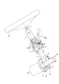
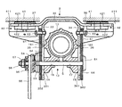
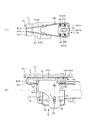
次に本発明の第2の実施形態について説明する。図5は本発明の第2の実施形態のステアリング装置の二次衝突前の状態を示し、(1)は(2)の平面図、(2)は要部の正面図である。図6は図5のステアリング装置の二次衝突後の状態を示し、(1)は(2)の平面図、(2)は要部の正面図である。以下の説明では、上記実施形態と異なる構造部分についてのみ説明し、重複する説明は省略する。
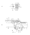
次に本発明の第3の実施形態について説明する。図7は本発明の第3の実施形態のステアリング装置の二次衝突前の状態を示し、(1)は(2)の平面図、(2)は要部の正面図である。図8は図7のステアリング装置の二次衝突後の状態を示し、(1)は(2)の平面図、(2)は要部の正面図である。以下の説明では、上記実施形態と異なる構造部分についてのみ説明し、重複する説明は省略する。
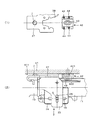
次に本発明の第4の実施形態について説明する。図9は本発明の第4の実施形態のステアリング装置の二次衝突前の状態を示し、(1)は(2)の平面図、(2)は要部の正面図である。図10は図9のステアリング装置の二次衝突後の状態を示し、(1)は(2)の平面図、(2)は要部の正面図である。以下の説明では、上記実施形態と異なる構造部分についてのみ説明し、重複する説明は省略する。
11 アウターコラム
12 ステアリングシャフト
121 ステアリングホイール
13 ディスタンスブラケット
14、15 側面
16、17 テレスコ調整用長溝
181、182 リブ
20 操舵補助部
21 ハウジング
22 下部車体取付けブラケット
221 枢動ピン
23 電動モータ
24 減速ギヤボックス部
25 出力軸
3 車体取付けブラケット
32 上板
33、34 側板
331、341 内側面
332、342 外側面
35、36 チルト調整用長溝
37、38 フランジ部
371、381 車体前方端
39 切欠き溝
41 車体
411 取付け面
412 案内溝
413 傾斜案内部
42 カプセル
421 上挟持板
421A 車体後方面
421B 右側面
421C 左側面
421D 車体前方面
422 下挟持板
43 ボルト
44 樹脂ピン
5 締付けロッド
51 頭部
53 固定カム
54 可動カム
55 操作レバー
56 スラスト軸受
57 ナット
58 雄ねじ
61 チルト用摩擦板
62 チルト調整用長溝
63 ボルト
64 テレスコ用摩擦板
65 テレスコ調整用長溝
66 ボルト
7 突起
71 折り曲げ部
72、73 突起
81 衝撃エネルギー吸収ワイヤー
81A 当接部
81B、81C 前方延長部
81D、81E 折り曲げ部
81F、81G 後方延長部
82 衝撃エネルギー吸収プレート
82A 矩形部
82B 矩形穴
82C 前方延長部
82D 折り曲げ部
82E 後方延長部
Claims (4)
- 車体後方側にステアリングホイールを装着可能なステアリングシャフト、
上記ステアリングシャフトを回動可能に軸支するステアリングコラム、
上記ステアリングコラムに取付けられた車体取付けブラケット、
上記車体取付けブラケットの左右両側のフランジ部に形成され、車体後方側が開放された切欠き溝、
上記切欠き溝の左右両側縁部を挟持する上下一対の挟持板を有し、車体の取付け面に固定可能で、二次衝突時に上記車体取付けブラケットを車体前方側に離脱可能に保持するカプセル、及び、
上記ステアリングコラムの軸心に平行且つ上記カプセルを上記車体の取付け面に固定するためのボルトの中心を通る線上において、上記フランジ部の上記挟持板よりも車体前方側であって上記車体の取付け面側に突出して形成された突起を備えたこと
を特徴とするステアリング装置。 - 請求項1に記載されたステアリング装置において、
上記突起は、上記車体の取付け面に対して微小な隙間を有していること
を特徴とするステアリング装置。 - 請求項1または請求項2のいずれかに記載されたステアリング装置において、
上記車体の取付け面には、
上記車体取付けブラケットの車体前方側への移動時に、上記突起を案内する案内溝が形成されていること
を特徴とするステアリング装置。 - 請求項1から請求項3までのいずれかに記載されたステアリング装置において、
上記フランジ部には、
上記突起とは異なる突起であって、上記挟持板の左右両側面から車体側方側に離間した位置に形成され、上記車体の取付け面側に突出する突起が更に備えられていること
を特徴とするステアリング装置。
Priority Applications (1)
| Application Number | Priority Date | Filing Date | Title |
|---|---|---|---|
| JP2005202333A JP4774841B2 (ja) | 2005-07-11 | 2005-07-11 | ステアリング装置 |
Applications Claiming Priority (1)
| Application Number | Priority Date | Filing Date | Title |
|---|---|---|---|
| JP2005202333A JP4774841B2 (ja) | 2005-07-11 | 2005-07-11 | ステアリング装置 |
Publications (2)
| Publication Number | Publication Date |
|---|---|
| JP2007015670A JP2007015670A (ja) | 2007-01-25 |
| JP4774841B2 true JP4774841B2 (ja) | 2011-09-14 |
Family
ID=37753187
Family Applications (1)
| Application Number | Title | Priority Date | Filing Date |
|---|---|---|---|
| JP2005202333A Expired - Fee Related JP4774841B2 (ja) | 2005-07-11 | 2005-07-11 | ステアリング装置 |
Country Status (1)
| Country | Link |
|---|---|
| JP (1) | JP4774841B2 (ja) |
Families Citing this family (11)
| Publication number | Priority date | Publication date | Assignee | Title |
|---|---|---|---|---|
| JP5034548B2 (ja) * | 2007-02-22 | 2012-09-26 | 日本精工株式会社 | ステアリングコラム装置 |
| JP5092880B2 (ja) * | 2007-05-17 | 2012-12-05 | 日本精工株式会社 | ステアリング装置 |
| JP5120115B2 (ja) * | 2008-07-04 | 2013-01-16 | 日本精工株式会社 | ステアリングコラムの支持装置 |
| JP5333417B2 (ja) * | 2009-12-11 | 2013-11-06 | 日本精工株式会社 | ステアリング装置 |
| JP5267447B2 (ja) * | 2009-12-24 | 2013-08-21 | 日本精工株式会社 | ステアリングコラムの支持装置 |
| JP5693997B2 (ja) * | 2011-02-24 | 2015-04-01 | 株式会社ジェイテクト | 車両用ステアリング装置 |
| WO2013080718A1 (ja) * | 2011-12-02 | 2013-06-06 | 日本精工株式会社 | ステアリング装置 |
| JP6079197B2 (ja) * | 2012-12-13 | 2017-02-15 | 日本精工株式会社 | 衝撃吸収式ステアリング装置 |
| JP6263415B2 (ja) * | 2014-02-27 | 2018-01-17 | Kyb株式会社 | ステアリング装置 |
| JP6442933B2 (ja) * | 2014-09-01 | 2018-12-26 | 株式会社ジェイテクト | ステアリング装置 |
| US11713068B2 (en) * | 2021-06-10 | 2023-08-01 | Yamada Manufacturing Co., Ltd. | Steering device |
Family Cites Families (4)
| Publication number | Priority date | Publication date | Assignee | Title |
|---|---|---|---|---|
| JPS61106481A (ja) * | 1984-10-29 | 1986-05-24 | Fujitsu Ltd | 半導体結晶の製造方法 |
| JPS6283782A (ja) * | 1985-10-09 | 1987-04-17 | 株式会社日立製作所 | 液晶表示装置 |
| JP3409513B2 (ja) * | 1995-07-14 | 2003-05-26 | 日本精工株式会社 | 衝撃吸収式ステアリング装置 |
| JP3409572B2 (ja) * | 1996-04-10 | 2003-05-26 | 日本精工株式会社 | 衝撃吸収式ステアリングコラム装置 |
-
2005
- 2005-07-11 JP JP2005202333A patent/JP4774841B2/ja not_active Expired - Fee Related
Also Published As
| Publication number | Publication date |
|---|---|
| JP2007015670A (ja) | 2007-01-25 |
Similar Documents
| Publication | Publication Date | Title |
|---|---|---|
| JP5333417B2 (ja) | ステアリング装置 | |
| US20070068311A1 (en) | Steering apparatus | |
| EP2692610B1 (en) | Steering column device | |
| JP5626350B2 (ja) | ステアリング装置 | |
| US20080284150A1 (en) | Steering system | |
| JP4774841B2 (ja) | ステアリング装置 | |
| JP5076673B2 (ja) | ステアリング装置 | |
| JP5257368B2 (ja) | ステアリング装置 | |
| JP5737297B2 (ja) | ステアリング装置 | |
| JP5223838B2 (ja) | ステアリング装置 | |
| JPWO2004005109A1 (ja) | 車両用衝撃吸収式ステアリングコラム装置 | |
| JP2010089612A (ja) | 衝撃吸収式ステアリングコラム装置 | |
| JP2012214188A (ja) | ステアリング装置 | |
| JP2008254510A (ja) | ステアリング装置 | |
| EP1533201A1 (en) | Steering column device | |
| JP2007283826A (ja) | ステアリング装置 | |
| JP4635772B2 (ja) | ステアリング装置 | |
| JP6819241B2 (ja) | ステアリング装置 | |
| JP5321537B2 (ja) | ステアリング装置 | |
| JP5233899B2 (ja) | 自動車の操作ペダル支持構造 | |
| JP5316472B2 (ja) | ステアリング装置 | |
| JP2005170141A (ja) | 車両用ステアリング装置 | |
| JP5664499B2 (ja) | ステアリング装置 | |
| JP5712767B2 (ja) | 衝撃吸収式ステアリング装置 | |
| JP2004322879A (ja) | ステアリングコラム装置 |
Legal Events
| Date | Code | Title | Description |
|---|---|---|---|
| A621 | Written request for application examination |
Free format text: JAPANESE INTERMEDIATE CODE: A621 Effective date: 20080617 |
|
| A977 | Report on retrieval |
Free format text: JAPANESE INTERMEDIATE CODE: A971007 Effective date: 20100730 |
|
| A131 | Notification of reasons for refusal |
Free format text: JAPANESE INTERMEDIATE CODE: A131 Effective date: 20110301 |
|
| A521 | Written amendment |
Free format text: JAPANESE INTERMEDIATE CODE: A523 Effective date: 20110421 |
|
| TRDD | Decision of grant or rejection written | ||
| A01 | Written decision to grant a patent or to grant a registration (utility model) |
Free format text: JAPANESE INTERMEDIATE CODE: A01 Effective date: 20110531 |
|
| A01 | Written decision to grant a patent or to grant a registration (utility model) |
Free format text: JAPANESE INTERMEDIATE CODE: A01 |
|
| A61 | First payment of annual fees (during grant procedure) |
Free format text: JAPANESE INTERMEDIATE CODE: A61 Effective date: 20110613 |
|
| R150 | Certificate of patent or registration of utility model |
Ref document number: 4774841 Country of ref document: JP Free format text: JAPANESE INTERMEDIATE CODE: R150 Free format text: JAPANESE INTERMEDIATE CODE: R150 |
|
| FPAY | Renewal fee payment (event date is renewal date of database) |
Free format text: PAYMENT UNTIL: 20140708 Year of fee payment: 3 |
|
| LAPS | Cancellation because of no payment of annual fees |