JP4635167B2 - Root cause diagnosis device for abnormalities in controlled processes - Google Patents
Root cause diagnosis device for abnormalities in controlled processes Download PDFInfo
- Publication number
- JP4635167B2 JP4635167B2 JP2003535005A JP2003535005A JP4635167B2 JP 4635167 B2 JP4635167 B2 JP 4635167B2 JP 2003535005 A JP2003535005 A JP 2003535005A JP 2003535005 A JP2003535005 A JP 2003535005A JP 4635167 B2 JP4635167 B2 JP 4635167B2
- Authority
- JP
- Japan
- Prior art keywords
- model
- detection
- industrial
- signal
- root cause
- Prior art date
- Legal status (The legal status is an assumption and is not a legal conclusion. Google has not performed a legal analysis and makes no representation as to the accuracy of the status listed.)
- Expired - Lifetime
Links
Images
Classifications
-
- G—PHYSICS
- G05—CONTROLLING; REGULATING
- G05B—CONTROL OR REGULATING SYSTEMS IN GENERAL; FUNCTIONAL ELEMENTS OF SUCH SYSTEMS; MONITORING OR TESTING ARRANGEMENTS FOR SUCH SYSTEMS OR ELEMENTS
- G05B23/00—Testing or monitoring of control systems or parts thereof
- G05B23/02—Electric testing or monitoring
- G05B23/0205—Electric testing or monitoring by means of a monitoring system capable of detecting and responding to faults
- G05B23/0218—Electric testing or monitoring by means of a monitoring system capable of detecting and responding to faults characterised by the fault detection method dealing with either existing or incipient faults
- G05B23/0243—Electric testing or monitoring by means of a monitoring system capable of detecting and responding to faults characterised by the fault detection method dealing with either existing or incipient faults model based detection method, e.g. first-principles knowledge model
- G05B23/0254—Electric testing or monitoring by means of a monitoring system capable of detecting and responding to faults characterised by the fault detection method dealing with either existing or incipient faults model based detection method, e.g. first-principles knowledge model based on a quantitative model, e.g. mathematical relationships between inputs and outputs; functions: observer, Kalman filter, residual calculation, Neural Networks
-
- G—PHYSICS
- G05—CONTROLLING; REGULATING
- G05B—CONTROL OR REGULATING SYSTEMS IN GENERAL; FUNCTIONAL ELEMENTS OF SUCH SYSTEMS; MONITORING OR TESTING ARRANGEMENTS FOR SUCH SYSTEMS OR ELEMENTS
- G05B13/00—Adaptive control systems, i.e. systems automatically adjusting themselves to have a performance which is optimum according to some preassigned criterion
- G05B13/02—Adaptive control systems, i.e. systems automatically adjusting themselves to have a performance which is optimum according to some preassigned criterion electric
- G05B13/0265—Adaptive control systems, i.e. systems automatically adjusting themselves to have a performance which is optimum according to some preassigned criterion electric the criterion being a learning criterion
- G05B13/0275—Adaptive control systems, i.e. systems automatically adjusting themselves to have a performance which is optimum according to some preassigned criterion electric the criterion being a learning criterion using fuzzy logic only
-
- G—PHYSICS
- G05—CONTROLLING; REGULATING
- G05B—CONTROL OR REGULATING SYSTEMS IN GENERAL; FUNCTIONAL ELEMENTS OF SUCH SYSTEMS; MONITORING OR TESTING ARRANGEMENTS FOR SUCH SYSTEMS OR ELEMENTS
- G05B21/00—Systems involving sampling of the variable controlled
- G05B21/02—Systems involving sampling of the variable controlled electric
-
- G—PHYSICS
- G05—CONTROLLING; REGULATING
- G05B—CONTROL OR REGULATING SYSTEMS IN GENERAL; FUNCTIONAL ELEMENTS OF SUCH SYSTEMS; MONITORING OR TESTING ARRANGEMENTS FOR SUCH SYSTEMS OR ELEMENTS
- G05B23/00—Testing or monitoring of control systems or parts thereof
- G05B23/02—Electric testing or monitoring
- G05B23/0205—Electric testing or monitoring by means of a monitoring system capable of detecting and responding to faults
- G05B23/0218—Electric testing or monitoring by means of a monitoring system capable of detecting and responding to faults characterised by the fault detection method dealing with either existing or incipient faults
- G05B23/0243—Electric testing or monitoring by means of a monitoring system capable of detecting and responding to faults characterised by the fault detection method dealing with either existing or incipient faults model based detection method, e.g. first-principles knowledge model
- G05B23/0245—Electric testing or monitoring by means of a monitoring system capable of detecting and responding to faults characterised by the fault detection method dealing with either existing or incipient faults model based detection method, e.g. first-principles knowledge model based on a qualitative model, e.g. rule based; if-then decisions
-
- G—PHYSICS
- G05—CONTROLLING; REGULATING
- G05B—CONTROL OR REGULATING SYSTEMS IN GENERAL; FUNCTIONAL ELEMENTS OF SUCH SYSTEMS; MONITORING OR TESTING ARRANGEMENTS FOR SUCH SYSTEMS OR ELEMENTS
- G05B23/00—Testing or monitoring of control systems or parts thereof
- G05B23/02—Electric testing or monitoring
- G05B23/0205—Electric testing or monitoring by means of a monitoring system capable of detecting and responding to faults
- G05B23/0259—Electric testing or monitoring by means of a monitoring system capable of detecting and responding to faults characterized by the response to fault detection
- G05B23/0275—Fault isolation and identification, e.g. classify fault; estimate cause or root of failure
- G05B23/0278—Qualitative, e.g. if-then rules; Fuzzy logic; Lookup tables; Symptomatic search; FMEA
-
- G—PHYSICS
- G05—CONTROLLING; REGULATING
- G05B—CONTROL OR REGULATING SYSTEMS IN GENERAL; FUNCTIONAL ELEMENTS OF SUCH SYSTEMS; MONITORING OR TESTING ARRANGEMENTS FOR SUCH SYSTEMS OR ELEMENTS
- G05B23/00—Testing or monitoring of control systems or parts thereof
- G05B23/02—Electric testing or monitoring
- G05B23/0205—Electric testing or monitoring by means of a monitoring system capable of detecting and responding to faults
- G05B23/0259—Electric testing or monitoring by means of a monitoring system capable of detecting and responding to faults characterized by the response to fault detection
- G05B23/0275—Fault isolation and identification, e.g. classify fault; estimate cause or root of failure
- G05B23/0281—Quantitative, e.g. mathematical distance; Clustering; Neural networks; Statistical analysis
-
- G—PHYSICS
- G05—CONTROLLING; REGULATING
- G05B—CONTROL OR REGULATING SYSTEMS IN GENERAL; FUNCTIONAL ELEMENTS OF SUCH SYSTEMS; MONITORING OR TESTING ARRANGEMENTS FOR SUCH SYSTEMS OR ELEMENTS
- G05B9/00—Safety arrangements
- G05B9/02—Safety arrangements electric
-
- G—PHYSICS
- G06—COMPUTING OR CALCULATING; COUNTING
- G06N—COMPUTING ARRANGEMENTS BASED ON SPECIFIC COMPUTATIONAL MODELS
- G06N5/00—Computing arrangements using knowledge-based models
- G06N5/02—Knowledge representation; Symbolic representation
- G06N5/022—Knowledge engineering; Knowledge acquisition
- G06N5/025—Extracting rules from data
-
- G—PHYSICS
- G05—CONTROLLING; REGULATING
- G05B—CONTROL OR REGULATING SYSTEMS IN GENERAL; FUNCTIONAL ELEMENTS OF SUCH SYSTEMS; MONITORING OR TESTING ARRANGEMENTS FOR SUCH SYSTEMS OR ELEMENTS
- G05B2219/00—Program-control systems
- G05B2219/30—Nc systems
- G05B2219/31—From computer integrated manufacturing till monitoring
- G05B2219/31464—Select between different models corresponding to diff process control configurations
Landscapes
- Engineering & Computer Science (AREA)
- Physics & Mathematics (AREA)
- General Physics & Mathematics (AREA)
- Automation & Control Theory (AREA)
- Artificial Intelligence (AREA)
- Mathematical Physics (AREA)
- Evolutionary Computation (AREA)
- Software Systems (AREA)
- General Engineering & Computer Science (AREA)
- Fuzzy Systems (AREA)
- Theoretical Computer Science (AREA)
- Quality & Reliability (AREA)
- Medical Informatics (AREA)
- Mathematical Analysis (AREA)
- Mathematical Optimization (AREA)
- Probability & Statistics with Applications (AREA)
- Pure & Applied Mathematics (AREA)
- Health & Medical Sciences (AREA)
- Algebra (AREA)
- Computational Linguistics (AREA)
- Data Mining & Analysis (AREA)
- Computing Systems (AREA)
- Computer Vision & Pattern Recognition (AREA)
- Testing And Monitoring For Control Systems (AREA)
- Feedback Control In General (AREA)
Description
本発明は、工業用プロセス制御装置およびプロセス制御ループに関する。特に、本発明は、そのようなループの診断装置に関する。 The present invention relates to an industrial process control device and a process control loop. In particular, the present invention relates to such a loop diagnostic apparatus.
プロセス制御ループは、プロセス工業で使用され、石油精製等のプロセスの運転を制御する。ループの代表的部分である送信機は、現場に設置されて、圧力、流量、または温度等のプロセス変数を測定し、例えば、制御室設備に送信する。バルブ制御装置のようなコントローラもまたプロセス制御ループの一部であり、制御ループを通して受信されたり内部で発生されたりした制御信号に基づいてバルブの位置を制御する。その他のコントローラは、例えば電動モータやソレノイドを制御する。制御室設備もまたプロセス制御ループの一部であり、制御室内のオペレータまたはコンピュータは、現場の送信機から受信したプロセス変数に基づいてプロセスを監視し、かつこれに応答して制御信号を適当な制御装置に送出することによってプロセスを制御できる。制御ループの一部となりえる他のプロセス装置は、プロセス制御ループ上のプロセス信号を監視して送信可能な携帯通信機である。一般的には、これらはループを形成する装置を構成するために使用される。 Process control loops are used in the process industry to control the operation of processes such as petroleum refining. A transmitter, which is a representative part of the loop, is installed in the field to measure and transmit process variables such as pressure, flow, or temperature to, for example, control room equipment. A controller, such as a valve controller, is also part of the process control loop and controls the position of the valve based on control signals received through the control loop or generated internally. Other controllers control, for example, electric motors and solenoids. The control room equipment is also part of the process control loop, and the operator or computer in the control room monitors the process based on the process variables received from the field transmitter and responds with appropriate control signals. The process can be controlled by sending it to the controller. Another process device that can be part of the control loop is a portable communicator that can monitor and transmit process signals on the process control loop. In general, they are used to construct devices that form loops.
プロセス制御ループの動作を監視してループ内の故障を診断し、かつ特定するために種々の手法が使用されている。しかし、例えば、プロセス運転での異常原因であるシステム中の個々の装置または構成要素を特定することによって、故障源つまり“根本原因”を特定することが、さらに望まれている。この根本原因は、プロセスのどの装置が修理もしくは交換を必要とするかについての付加的な情報をオペレータに提供する。 Various techniques have been used to monitor the operation of the process control loop to diagnose and identify faults within the loop. However, it is further desirable to identify the failure source or “root cause”, for example, by identifying individual devices or components in the system that are the cause of the abnormalities in process operation. This root cause provides the operator with additional information about which equipment in the process requires repair or replacement.
種々の観点において、工業用プロセスにおける異常源つまり“根本原因”を特定することができる工業用プロセス診断装置が提供される。一つの観点では、診断装置は複数のプロセス形成モデルを含み、各モデルは工業用プロセスの物理的(つまり実際の)実装(implementation)に関連する。複数のモデルのうちの一つが選択され、選択されたモデルおよびプロセスに関する少なくとも一つののプロセス信号が使用されて診断が実行される。この診断に基づいて異常の根本原因が決定される。 In various aspects, an industrial process diagnostic apparatus capable of identifying an abnormal source or “root cause” in an industrial process is provided. In one aspect, the diagnostic device includes a plurality of process formation models, each model associated with a physical (ie, actual) implementation of an industrial process. One of the plurality of models is selected and at least one process signal for the selected model and process is used to perform a diagnosis. Based on this diagnosis, the root cause of the abnormality is determined.
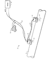
本発明は、プロセスで発生する異常の“根本原因”を特定するために工業プロセスで使用することができる。図1は、プロセス流体システム2の流量を制御するのに使用される工業プロセス制御システム2の一例を示す図であり、プロセス流体を搬送するプロセスパイプ4およびループ電流Iを流す2線プロセス制御ループ6を含む。送信機8と、アクチュエータ、バルブ、ポンプ、モータまたはソレノイドのようなループ内の最終的な制御要素に接続されるコントローラ10と、通信機12と、制御室14は、全てプロセス制御システム2の一部である。プロセスの運転中に異常が発生すると、本発明は、観測された異常の原因を特定するために使用される。
The present invention can be used in industrial processes to identify "root causes" of abnormalities that occur in the process. FIG. 1 is a diagram illustrating an example of an industrial process control system 2 used to control the flow rate of a process fluid system 2, a process pipe 4 carrying process fluid and a two-wire process control loop for passing a loop current I 6 is included. The transmitter 8, the
ループ6は、図示目的のために一形態で示されているが、4−20mAループ、2,3または4線ループ、マルチドロップループ、ハート(HART:登録商標)またはフィールドバス(FieldBus)またはその他のデジタルまたはアナログ通信プロトコルに従って動作するループのような、いかなる適当なプロセス制御ループでも使用することができる。運転中、送信機8は、流量などのプロセス変数をセンサ16で感知し、感知されたプロセス変数をループ6を介して送信する。プロセス変数は、コントローラ/バルブアクチュエータ10、通信機12および/または制御室設備14で受信される。コントローラ10は、バルブ18に結合されて図示されており、バルブ18を調節してプロセスを制御し、それによってパイプ4内の流量を変化させることができる。コントローラ10は、ループ6を介して、例えば、制御室14、送信機8または通信機12から制御入力を受信し、それに応答してバルブ18を調節する。別の実施例では、コントローラ10は、ループ6を介して受信したプロセス信号に基づいて制御信号を内部的に発生する。通信機12は、図1に示されている携帯通信機であってもよいし、プロセスを監視して計算を実行する、固定的に設置されたプロセスユニットであってもよい。プロセス装置は、例えば、図1に示す、送信機8{ローズマウント インコーポレイテッド(Rosemount Inc.)から入手できる3095型送信機等}、コントローラ10、通信機12、および制御室14を含む。別のタイプのプロセス装置は、PC、プログラム可能論理ユニット(PLC)、または、ループ上の監視、管理、および/または送信を可能にするための適当なI/O回路を使ってループに結合される、その他のコンピュータである。
Loop 6 is shown in one form for illustration purposes, but is a 4-20 mA loop, a 2, 3 or 4 wire loop, a multi-drop loop, a HART® or a Fieldbus or others Any suitable process control loop can be used, such as a loop operating according to other digital or analog communication protocols. During operation, the transmitter 8 senses a process variable such as a flow rate with the
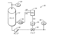
図2は、タンク52内の液体のレベルを制御するためのプロセス制御ループ50のグラフィックモデルの簡略図である。後述するように、このようなモデルは、プロセス運転中の異常の根本原因を診断するために選択して使用されることができる。レベル送信機54は、タンク52内の液体の高さを測定し、基本プロセス変数(PV)をコントローラ56に提供する。コントローラ56は、PIDコントローラが図示されているが、いかなるタイプのコントローラであってもよい。コントローラ56は、またタンク52内の液体の所望レベルに関連する設定ポイント(SP)を受信する。コントローラ56は、公知の制御アルゴリズムを使って、制御要求(CD)出力をバルブ58に提供する。オプションであるバルブ位置センサ60を使用してバルブ58の弁棒の実際位置を測定することができる。この具体例のモデルでは、その他のオプション構成要素として、タンク52から液体を引き出すように構成されたポンプ62、入口流速を測定するように構成された送信機64、および出口流速を測定するように構成された送信機66を含む。後述するように、モデルおよびモデルのためのオプション構成要素は、メモリ内に記憶され、オペレータまたはその他の選択手法によって選択することができる。異なる観点において、メモリは、プロセスに結合されるかプロセス信号へのアクセスを持つどのような装置に対しても配置でき、アクセス可能とすることができる。
FIG. 2 is a simplified diagram of a graphic model of a
プロセス制御システム上での本発明の診断は、プロセスの運転が安定して定常モードになった後に実行されるのが好ましい。定常モードは、プロセス信号の平均および標準偏差を観察することによって確認される。各々のプロセス信号(プロセス変数および制御信号等)の平均(μ)および標準偏差(Σ)は、N組の測定値に関して計算され、平均および標準偏差は次のように計算される。 The diagnosis of the present invention on the process control system is preferably performed after the process operation has stabilized and entered steady mode. Steady mode is confirmed by observing the mean and standard deviation of the process signal. The average (μ) and standard deviation (Σ) of each process signal (such as process variables and control signals) is calculated for N sets of measurements, and the average and standard deviation are calculated as follows.
![]()
![]()

ポイント数Nは、信号のサンプル期間およびサンプリング速度に依存する。数式1および2において、Xiはサンプル番号iで採取されたプロセス信号の値である。最初に、毎秒1サンプルのサンプル速度でもって10分間のサンプル期間が使用される。一例では、プロセス平均が2540mmH2O(=100inH2O)(25.4mmH2O(=1inH2O)標準偏差をもって)であり、その後のプロセス平均が2463.8mmH2O(=97inH2O)と2616.2mmH2O(=103inH2O)の間であるならば、そのループは定常モードで運転されていると決定される。診断の開始に先立つプロセス安定の判断に関連する特許が米国特許第6,119,047号として2000年9月12日に発行されており、その全体が参照によりここに合体される。
The number of points N depends on the sample period and sampling rate of the signal. In
一旦定常運転に到達したならば、他の部分の平均的なデータから一時的に大きく変化するパルス状のデータつまりスパイクは廃棄するのが望ましい。そのようなデータを特定するための一つの手法は、信号標準偏差をもって信号平均を連続的に比較することである。それぞれN組の測定値を提供する二つの連続する各信号ブロック(以下の「ブロック」も同様の内容を持つ)の測定値の平均(μ1およびμ2)の差は、サンプル数Nの平方根で除算された標準偏差より小さくなければならない。これは、次のように表される。 Once steady operation is reached, it is desirable to discard pulsed data, that is, spikes that temporarily change significantly from the average data of other parts . One way to identify such data is to continuously compare signal averages with signal standard deviation. The difference in the mean (μ1 and μ2) of the measurements of two consecutive signal blocks (the following “blocks”, which have the same content) each providing N sets of measurements, is divided by the square root of the number of samples N Must be less than the standard deviation. This is expressed as follows.
![]()
![]()
ここで、μ1は前ブロックの平均であり、μ2は現ブロックの平均であり、Nはブロック内のポイント数であり、σ1は前ブロックの標準偏差である。 Here, μ 1 is the average of the previous block, μ 2 is the average of the current block, N is the number of points in the block, and σ 1 is the standard deviation of the previous block.
診断を実行するために入手可能であってモデルで使用されるプロセス信号に依存し、異なる根本原因が特定される。例えば、図2に示すプロセスモデルの場合、三つの異なったケースが存在する。 Depending on the process signals available to perform the diagnosis and used in the model, different root causes are identified. For example, in the case of the process model shown in FIG. 2, there are three different cases.
初期トレーニングフェーズの間、全てのプロセス信号は、例えば20分間収集される。この時間は、ユーザが選択可能である。これらの信号の平均および標準偏差が計算される。このトレーニングフェーズは、プロセスが安定状態に入るまで繰り返される。一旦プロセスが安定状態になれば、各々のプロセス信号の平均(μt)および標準偏差(σt)の照準値(つまり公称値)が記憶される。 During the initial training phase, all process signals are collected, for example for 20 minutes. This time can be selected by the user. The mean and standard deviation of these signals are calculated. This training phase is repeated until the process enters a stable state. Once the process is in a steady state, the mean (μ t ) and standard deviation (σ t ) aim values (ie nominal values) of each process signal are stored.
さらに、故障の根本原因の特定に先立ち、プロセスが適切に運転されていることを確認するため、個々のプロセス信号が評価される。例えば、基本プロセス変数(PV)が評価される。図2に図示された液体レベルの場合は、次のように評価される。 In addition, prior to identifying the root cause of the failure, individual process signals are evaluated to confirm that the process is operating properly. For example, basic process variables (PV) are evaluated. In the case of the liquid level shown in FIG. 2, the evaluation is as follows.
ここで、PV_RANGEは、液体レベルのレンジ(最大値および最小値の範囲)である。この値は、プロセス制御システムが形成された時にプロセス制御システムによってアクセス可能なメモリ内に記憶されるか、ユーザによって入力される。同様に、制御信号(CD)では次の故障が特定される。 Here, PV_RANGE is a range of the liquid level (maximum value and minimum value range). This value is stored in a memory accessible by the process control system when the process control system is formed or entered by the user. Similarly, the next failure is specified in the control signal (CD).
表3の例において、制御要求は0%と100%の間にあると想定される。できることならば、同様のテストがバルブ位置(VP)プロセス信号について実行される。 In the example of Table 3, the control request is assumed to be between 0% and 100%. If possible, a similar test is performed on the valve position (VP) process signal.
監視フェーズの間、種々のプロセス信号が監視され、これらが変化なし(NC)、上方変化(U)(平均信号がトレーニングフェーズで得られた平均より大)、もしくは下方変化(D)(平均信号がトレーニングフェーズで得られた平均より小)であるかが判断される。NCの状態は数式4で判断される。 During the monitoring phase, the various process signals are monitored and these are unchanged (NC), up (U) (average signal is greater than the average obtained in the training phase ), or down (D) (average signal Is smaller than the average obtained in the training phase . The state of NC is determined by Equation 4.
![]()
![]()
数式4において、μtはトレーニングフェーズで得られた平均、μは現ブロックの平均、Nはブロック内のポイント数であり、σtはトレーニングフェーズで得られた標準偏差、μtおよびσtはそれぞれ、トレーニングフェーズで記憶された平均および標準偏差である。Nはサンプル数、μは現在のプロセス信号の平均である。 In Equation 4, μt is the average obtained in the training phase , μ is the average of the current block, N is the number of points in the block, σt is the standard deviation obtained in the training phase , μt and σt are the training phase, respectively. Is the mean and standard deviation stored in N is the number of samples and μ is the average of the current process signal.
上方変化(U)の状態は数式5で特定される。 The state of upward change (U) is specified by Equation 5.
![]()
![]()
ここで、μtはトレーニングフェーズで得られた平均、μは現ブロックの平均、Nはブロックのポイント数であり、σtはトレーニングフェーズで得られた標準偏差である。 Here, μt is the average obtained in the training phase , μ is the average of the current block, N is the number of points in the block, and σt is the standard deviation obtained in the training phase .
最後に、下方変化(D)の状態は数式6で特定される。 Finally, the state of downward change (D) is specified by Equation 6.
![]()
![]()
ここで、μtはトレーニングフェーズで得られた平均、μは現ブロックの平均、Nはブロック内のポイント数であり、σtはトレーニングフェーズで得られた標準偏差である。 Here, μt is the average obtained in the training phase , μ is the average of the current block, N is the number of points in the block, and σt is the standard deviation obtained in the training phase .
入手可能なプロセス信号の数によって、プロセス内の異常源として異なる根本原因を特定することができる。例えば、設定ポイント、基本変数および制御要求プロセス信号を入手できるならば、レベルセンサのドリフトまたはバルブに関連する問題を特定することができる。ルールベースの一例を表4に示す。 Depending on the number of process signals available, different root causes can be identified as sources of anomalies in the process. For example, if setpoints, basic variables and control request process signals are available, problems associated with level sensor drift or valves can be identified. An example of the rule base is shown in Table 4.
付加的なプロセス信号を入手できるならば、表5に示すように、実際のバルブ位置(VP)、そして根本原因をより具体的に特定することができる。 If additional process signals are available, the actual valve position (VP) and the root cause can be more specifically identified, as shown in Table 5.
最後に、流入速度(IF)および流出速度(OF)プロセス信号を入手できるならば、図6のルールベースで示されるようにタンク52内に漏れが存在するかどうかを判断することも可能である。
Finally, if inflow rate (IF) and outflow rate (OF) process signals are available, it is also possible to determine whether there is a leak in
プロセス信号の変化が前記表4,5および6のいずれのルールにも一致しない場合、未知異常出力を出力することができる。また、これらのルールは、プロセス50がポンプ62を含むかタンク52の排水に使用される圧力差に基づいて動作する場合に適合する。
If the change in the process signal does not match any of the rules in Tables 4, 5 and 6, an unknown abnormality output can be output. These rules also apply when the
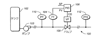
図3は、流速を制御するプロセス制御ループのグラフィックモデル100の簡略図である。これは、プロセス制御ループの別の例を図示している。図3において、タンク102(またはポンプ103もしくはその他の差圧源)は、処理流体の流れを提供することができる。送信機104は、流速を感知して基本プロセス変数(流速)をコントローラ106に提供する。コントローラ106はまた設定ポイント(SP)を受信し、制御要求(CD)信号をバルブ108に提供する。バルブ108は、その弁棒の実際位置(VP)をオプションに従って任意に返送することができる。追加のオプションは、プロセス圧力(PT)を感知するように構成された圧力送信機110および冗長流速(FT2)を感知するように構成された冗長流量送信機112を含む。
FIG. 3 is a simplified diagram of a
動作中、図2に関して記述されたのと同様の方法で、また、数式1および2で説明されたように、トレーニングフェーズの間、平均および標準偏差が決定される。しかし、一般的に流速制御は比較的速く応答するので、より短いトレーニングフェーズの期間、例えば2分が使用される。
In operation, the mean and standard deviation are determined during the training phase in a manner similar to that described with respect to FIG. 2 and as described in
表7に示されるように、入手できる異なるプロセス信号の数に応じて、異なる根本原因の数が特定される。 As shown in Table 7, depending on the number of different process signals available, different root cause numbers are identified.
根本原因の特定に先立ち、例えば、表8のルールベースを使って基本的な故障がチェックされる。 Prior to identifying the root cause, basic faults are checked using, for example, the rule base of Table 8.
また、バルブの状態は次のように判断される。 The state of the valve is determined as follows.
追加的なプロセス変数を使用することによって、プロセス内の異常の“根本原因”が特定される。設定ポイント、基本プロセス変数および制御要求信号を入手できる場合、プロセス異常の根本原因として、流量センサのドリフトまたはバルブのトラブルを次のように特定できる。 By using additional process variables, the “root cause” of the anomaly in the process is identified. If set points, basic process variables, and control request signals are available, flow sensor drift or valve trouble can be identified as the root cause of process anomalies as follows.
追加的なプロセス信号が入手できるならば、実際のバルブ位置(VP)と同時に、流量センサのドリフトもしくはバルブのトラブルを根本原因として次のように特定できる。 If additional process signals are available, the actual valve position (VP) and the flow sensor drift or valve trouble can be identified as the root cause as follows.
最後に、第2の流速変数(FT2)を測定するため、冗長送信機が使用されるならば、プロセス内の漏れを特定することもできる。 Finally, if a redundant transmitter is used to measure the second flow rate variable (FT2), a leak in the process can also be identified.
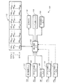
図4は、本発明の一実施形態を実装したプロセス装置100を示すブロック図である。プロセス装置100は、制御信号入力104を通して制御信号CDを受信し、プロセス変数入力106を通してプロセス変数PVを受信し、設定ポイント入力108を通して設定ポイントSPを受信する根本原因分析ブロック102を含む。追加的なプロセス信号(PS1,PS2…)は、プロセス信号入力110,111のような、入手できる追加的なプロセス信号の数に応じたその他の入力を通じて受信される。
FIG. 4 is a block diagram illustrating a
根本原因分析ブロック102は、また複数のプロセス形成モデル112を記憶するメモリに接続される。プロセス形成モデル112は、例えばシステムメモリ内に記憶される。図示された実施形態において、可能なプロセス制御ループに対応した全部でX個の異なったプロセス形成モデルが存在する。この例では、各プロセス形成モデルは、プロセスのグラフィック表現を提供するグラフィックモデルGM1…GMxを含む。これは、オペレータによる構成データの入力を容易にするグラフィック・ユーザ・インタフェースを提供するために使用される。例えば、グラフィックモデルは、図2および図3に図示したものと同様のものでよい。
The root
各々のプロセス形成モデルは、どのような数のプロセス信号(PS1A,PS1B,…等)でも受信することができる。図2,3に示された具体例においては、プロセス内における異常の根本原因を特定するために必要とされる最少三つのプロセス信号、つまり制御要求CD、主要なプロセス変数PVおよび設定ポイントSPが存在する。ある実施形態において、プロセス形成モデルに関連するプロセス信号の数は、要求されるように、根本原因分析を実施するのに必要とされるプロセス信号の最少数であるか、それより多い数である。 Each process formation model can receive any number of process signals (PS1A, PS1B,...). In the example shown in FIGS. 2 and 3, a minimum of three process signals required to identify the root cause of an anomaly in the process, namely control request CD, main process variable PV and set point SP, Exists. In some embodiments, the number of process signals associated with the process formation model is the minimum or greater number of process signals required to perform the root cause analysis, as required. .
次に、各プロセス形成モデルは、オプションのプロセス信号(OP1A,OP1B,…)をいくつでも含むことができる。各オプションのプロセス信号は、入力110,111等を通して受信されるプロセス信号(PS1,PS2,…)に相当する。図2の例において、バルブ位置VP、流入速度IFおよび流出速度OFは、オプションのプロセス信号の例である。いくつかのプロセス形成モデルは、オプションのプロセス信号を持たないように構成することができる。
Each process formation model can then include any number of optional process signals (OP1A, OP1B,...). Each optional process signal corresponds to a process signal (PS1, PS2,...) Received through
次に、各プロセス形成モデルは、受信したプロセス信号(必要とされる最少のプロセス信号PS1A,PS1B…ならびにいくつかのオプションのプロセス信号OP1A,OP1B,…)に基づいて根本原因を決定するために使用されるルールベースをいくつでも含むことができる。図4では、ルールベースは、RB1A,RBP1B,…で示されている。ルールベースの例は、上述の表4,5,6,10,11および12に示されている。本発明は、根本原因の分析を実施するために上記ルールベースを特別に使用することに限定されないことに注意すべきである。一つの観点では、ニューラルネットワーク、その他のルールベース、回帰学習、ファジー論理およびその他の公知の診断手法またはまだ発見されていない手法を含むいかなる分析手法をも使用することができる。ここに示した例では、受信される最少三つのプロセス信号として、制御要求CD信号、主要なプロセス変数PVおよび設定ポイントSP信号が存在する。しかし、その他の信号、より少ない信号または異なる信号の組み合わせを根本原因分析の実行のために使用することができる。 Each process formation model then determines the root cause based on the received process signals (minimum required process signals PS1A, PS1B... And some optional process signals OP1A, OP1B,...). Any number of rule bases used can be included. In FIG. 4, the rule bases are indicated by RB1A, RBP1B,. Examples of rule bases are shown in Tables 4, 5, 6, 10, 11 and 12 above. It should be noted that the present invention is not limited to the specific use of the rule base to perform root cause analysis. In one aspect, any analysis technique can be used, including neural networks, other rule bases, regression learning, fuzzy logic, and other known diagnostic techniques or techniques that have not yet been discovered. In the example shown here, there are a control request CD signal, a main process variable PV and a set point SP signal as a minimum of three process signals received. However, other signals, fewer signals, or combinations of different signals can be used to perform root cause analysis.
根本原因分析ブロック102は、モデル選択入力116を受信し、複数のプロセス形成モデル112の内の一つを選択する。モデル選択入力は、オペレータまたは別のソースからのものでよい。モデル選択入力116は、根本原因分析ブロック102で連続的に使用される唯一のプロセス形成モデルを特定する。また、一つの例では、選択されたプロセス形成モデルに含まれる追加的なオプションのプロセス(OP)信号が根本原因分析ブロック102で使用される。なお、OP信号は、入力110,111等を通して実際に受信されるプロセス信号(PS1,PS2,…)に相当する。グラフィック・ユーザ・インタフェースが使用される場合、グラフィックモデルが表示出力118上に表示される。例えば、モデル選択入力116により選択されたプロセス形成モデルに関連するプロセス信号(PS1A,PS1B,…)またはオプションのプロセス信号(OP1A,OP1B,…)が該プロセス形成モデルにおけるプロセス信号に割り当てられる。この割り当てをグラフィック形式で表示してもよい。
Root
一旦、プロセス形成モデルが選択されると、プロセス形成モデルのルールベースによって使用されるプロセス信号は、プロセスから受信される実際のプロセス信号に割り当てられる。根本原因分析ブロック102は、上述したような、要求される手法のいずれかを使って根本原因分析を実行する。根本原因分析に基づいて、プロセス内で発生したイベントの異常の根本原因を示す根本原因出力120が提供される。
Once the process formation model is selected, the process signal used by the process formation model rule base is assigned to the actual process signal received from the process. The root
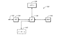
本発明の一実施形態に従った図5は、プロセス装置100の一物理的実装を示す簡略ブロック図である。図5の例では、装置100は、入出力部134を通してプロセス制御ループ132に接続される。ループ132は、例えば、図1に示される2線ループもしくはその他のプロセス制御ループである。また、接続は、直接接続である必要はなく、ループからの変数が論理入力出力ブロック134を通して受信される論理接続だけでもよい。マイクロプロセッサ136は、メモリ138およびグラフィック・ユーザ・インタフェース140に接続される。メモリ138は、図4に示されるプロセス形成モデル112だけでなく、変数およびプログラム命令を記憶するために使用される。
FIG. 5 in accordance with one embodiment of the present invention is a simplified block diagram illustrating one physical implementation of
グラフィック・ユーザ・インタフェース140は、プロセス形成モデルの選択および形成の期間に使用される図4の表示出力118だけでなくモデル選択入力116を受信するための入力を提供する。マイクロプロセッサ136は、また監視されるプロセスの形態および動作に関連する情報を含むオプションのデータベース142に接続することができる。例えば、多くのプロセス制御または監視システムはこのようなデータベースを有する。一例は、ミネソタ州エデンプレーリのローズマウント・インコーポレーションから入手できるAMSシステムである。
The
根本原因プロセス装置100は、送信機、コントローラ、携帯通信機、または図1に示したような制御室のようなあらゆるプロセス装置において実施することができる。一実施形態において、プロセス装置100は、制御室または他の遠隔場所に配置されたコンピュータシステムつまりPC上で動作する。プロセス制御ループ132は、一般的にはいくつかのタイプのフィールドバスを基礎にしたループ、または複合制御ループからなる。このような形態では、プロセス装置100は、選択されたプロセス形成モデルに対する制御ループに接続された種々の装置に所望のプロセス信号を投ずることができる。グラフィック・ユーザ・インタフェース140が示されているが、プロセス形成モデルは、どのような選択手法で選択されてもよく、人の操作によって選択および形成される必要はない。例えば、別の場所に格納された構成情報が他の手法によって与えられることに基づいて、適当なルールベースおよびモデルオプションが装置100によって受信されてもよい。その代わりに、根本原因プロセス装置100は、例えば現場に設備され、送信機内に配置されてもよい。
The root
ここで使用されたプロセス変数は、一般的にプロセス内で制御されている基本変数である。ここで使用されたプロセス変数は、例えば、圧力、流量、温度、製品レベル、pH、混濁、振動、位置、モータ電流、およびその他のプロセスの特性等の、プロセスの状態を表すあらゆる変数を意味する。制御信号は、プロセスを制御するために使用されるあらゆる信号(プロセス変数以外のもの)を意味する。例えば、制御信号は、所望の温度、圧力、流量、製品レベル、pH、または混濁等の、コントローラによって調節されるか、プロセスを制御するために使用される所望のプロセス変数値(すなわち設定ポイント)を意味する。また、制御信号は、較正値、警報、警報状態、バルブアクチュエータに供給されるバルブ位置信号や加熱要素に供給されるエネルギレベルやソレノイドのオン・オフ信号等のように制御要素へ供給される信号、またはプロセスの制御に関連する他のあらゆる信号を意味する。ここで使用された診断信号は、プロセス制御ループ内の装置および要素の動作に関連する情報を含む。しかし、プロセス変数や制御信号は含まない。例えば、診断信号は、弁棒の位置、印加されたトルクつまり力、アクチュエータの圧力、バルブを駆動させるために使用される圧縮ガスの圧力、電圧、電流、電力、抵抗、容量、インダクタンス、装置温度、スティクション、摩擦、フルオンおよびフルオフ位置、行程、周波数、振幅、スペクトルおよびスペクトル成分、剛性、電界もしくは磁界の強さ、期間、強度、動作、電動モータの逆起電力、モータ電流、ループ関連パラメータ(制御ループ抵抗、電圧、または電流等)、またはシステム内で検出あるいは測定される他のあらゆるパラメータを含む。さらに、プロセス信号は、例えば、プロセス変数、制御信号または診断信号のようなプロセス内のプロセスまたは要素に関連するあらゆる信号を意味する。プロセス装置は、プロセスループの一部を形成するかプロセスループに接続されてプロセスの制御または監視に使用されるあらゆる装置を含む。 The process variables used here are basic variables that are generally controlled within the process. As used herein, process variable means any variable that represents the state of the process, such as pressure, flow rate, temperature, product level, pH, turbidity, vibration, position, motor current, and other process characteristics. . A control signal refers to any signal (other than a process variable) used to control a process. For example, the control signal may be adjusted by a controller, such as a desired temperature, pressure, flow rate, product level, pH, or turbidity, or a desired process variable value (ie, set point) used to control the process. Means. In addition, the control signal is a signal supplied to the control element such as a calibration value, an alarm, an alarm state, a valve position signal supplied to the valve actuator, an energy level supplied to the heating element, a solenoid on / off signal, etc. Or any other signal related to process control. The diagnostic signal used here includes information related to the operation of the devices and elements in the process control loop. However, process variables and control signals are not included. For example, diagnostic signals can include valve stem position, applied torque or force, actuator pressure, compressed gas pressure used to drive the valve, voltage, current, power, resistance, capacity, inductance, device temperature , Stiction, friction, full-on and full-off positions, stroke, frequency, amplitude, spectral and spectral components, stiffness, electric or magnetic field strength, duration, strength, operation, electric motor back electromotive force, motor current, loop related parameters (Such as control loop resistance, voltage or current) or any other parameter detected or measured in the system. Furthermore, a process signal means any signal associated with a process or element within the process, such as, for example, a process variable, a control signal or a diagnostic signal. Process equipment includes any equipment that forms part of or is connected to a process loop and is used to control or monitor the process.
本発明は、好ましい実施形態を参照して説明されたが、当業者は形態および細部において本発明の精神および範囲から逸脱しないで変更できることを認識できるであろう。この明細書中では、二つの具体的処理例および具体的モデル例が示されたが、本発明は、公知の手法または将来発見される手法を使って生成されるその他の形態およびモデルに適合できる。また、他のタイプのルールベースまたはモデル形態が本発明で使用されてもよい。本発明は、独立した装置として設備でき、また、工業プロセスの制御または監視に使用されるソフトウェアに追加されるソフトウェアモジュールであってもよい。一つの観点では、本発明は、本発明を実施するために使用されるコンピュータ命令および/または記憶媒体を含む。ここで使用された“プロセスモデル”は、あらゆるプロセスの論理表現であり、上述の具体例に限定されない。“根本原因”はプロセス運転中の変化もしくは異常の初期原因(または複数原因)である。モデル化される他のタイプのプロセス制御ループは、ガス、液体、固体または他の形態のプロセス材料の調整制御およびカスケード制御を含む流量制御、レベル制御、温度制御などを含むが、これに限定されない。ループの特別な具体例は、例えば、差圧によって駆動されるバルブを備えた流量制御ループ、差圧によって駆動されるバルブを備えたレベル制御ループ、流量調整制御のための温度調整制御、バルブポンプ駆動のためのレベル調整制御、ポンプによって駆動されるバルブを備えた流量制御、バルブ冷却凝縮器のためのレベル調整制御、流量調整制御カスケード供給のためのレベル調整制御、バルブのための液体温度調整制御、流量調整制御のための液体温度調整制御、差圧によって駆動されるバルブを備えたガス流量制御、バルブのためのガス温度調整制御、バルブのためのガス圧調整制御、流量調整制御のためのガス圧調整制御、流力調整制御カスケードリボイラのためのレベル調整制御、バルブリボイラのバルブおよびレベル調整制御のための液体圧力調整制御を含む。制御される種々のタイプのプロセス要素は、例えば、巻胴およびタンク、熱交換器、塔、蒸気系、凝縮器、ボイラ、反応器、加熱器、圧縮機、燃料系、タービン、およびフレア系を含む。 Although the present invention has been described with reference to preferred embodiments, workers skilled in the art will recognize that changes may be made in form and detail without departing from the spirit and scope of the invention. In this specification, two specific processing examples and specific model examples are shown, but the present invention can be adapted to other forms and models generated using known techniques or techniques discovered in the future. . Other types of rule bases or model forms may also be used with the present invention. The present invention may be a software module that can be installed as an independent device and added to the software used to control or monitor industrial processes. In one aspect, the invention includes computer instructions and / or storage media used to implement the invention. The “process model” used here is a logical expression of all processes, and is not limited to the specific examples described above. “Root cause” is the initial cause (or multiple causes) of changes or anomalies during process operation. Other types of process control loops that are modeled include, but are not limited to, flow control, level control, temperature control, etc., including regulation control and cascade control of gas, liquid, solid or other forms of process material . Specific examples of loops include, for example, a flow control loop with a valve driven by differential pressure, a level control loop with a valve driven by differential pressure, a temperature control for flow control, a valve pump Level adjustment control for driving, flow control with valve driven by pump, level adjustment control for valve cooling condenser, level adjustment control for cascade adjustment of flow rate control, liquid temperature adjustment for valve Control, liquid temperature adjustment control for flow rate adjustment control, gas flow rate control with valve driven by differential pressure, gas temperature adjustment control for valve, gas pressure adjustment control for valve, flow rate adjustment control Gas pressure adjustment control, flow force adjustment control level adjustment control for cascade reboiler, valve reboiler valve and level adjustment control It includes a liquid pressure adjustment control fit. The various types of process elements that are controlled include, for example, winding drums and tanks, heat exchangers, towers, steam systems, condensers, boilers, reactors, heaters, compressors, fuel systems, turbines, and flare systems. Including.
2……工業プロセス制御システム
4……プロセスパイプ
6……2線プロセス制御ループ
8……送信機
10……コントローラ
12……通信機
14……制御室
16……センサ
18……バルブ
100……プロセス装置
102……根本原因分析ブロック
104……制御信号入力
106……プロセス変数入力
108……設定ポイント入力
110,111……プロセス信号入力
112……プロセス形成モデル
116……モデル選択入力
118……表示出力
120……根本原因出力
2 ... Industrial process control system 4 ... Process pipe 6 ... 2-wire process control loop 8 ...
Claims (21)
複数のプロセス形成モデルを記憶するメモリであって、各々のプロセス形成モデルが、工業プロセスの、タイプが異なる複数のプロセス制御ループの各々での基本的なプロセス処理用および検出用の構成要素の物理的な接続関係、さらにプロセス処理用および検出用のオプションの構成要素が追加された場合には該プロセス処理用および検出用のオプションの構成要素の物理的な接続関係も表すモデルと、前記基本的な検出用の各構成要素で検出されるプロセス信号に基づいて異常の根本原因を決定するために使用されるルールベース、さらに前記プロセス処理用および検出用のオプションの構成要素が追加された場合に該検出用のオプションの構成要素で検出されるプロセス信号をも用いて異常の根本原因を決定するために使用されるルールベースを含んでいる複数のプロセス形成モデルを記憶するメモリと、
前記基本的なプロセス処理用および検出用の構成要素の物理的な接続関係を表すモデルに前記プロセス処理用および検出用のオプションの構成要素を追加するように構成され、また、前記メモリに記憶された複数のプロセス形成モデルのうちの唯一のプロセス形成モデルを特定し、該プロセス形成モデルを前記メモリから読み出すように構成された選択入力手段と、
前記選択入力手段により読み出されたプロセス形成モデルに含まれるモデルの、検出用の各構成要素で検出されるプロセス信号を入力するように構成された信号入力手段と、
前記選択入力手段により読み出されたプロセス形成モデルに含まれるモデルの工業プロセスにおける異常の根本原因を示す根本原因出力を出力する根本原因分析手段であって、前記選択入力手段により読み出されたプロセス形成モデルに含まれるモデルの、検出用の各構成要素で検出されるプロセス信号に基づいて異常の根本原因を決定するルールベースと前記信号入力手段によって入力されたプロセス信号を入力として異常の根本原因を判定し、その判定結果を異常の根本原因出力として送出する根本原因分析手段とからなる工業プロセス診断装置。In industrial process diagnostic equipment for identifying the root cause of abnormalities in industrial processes,
A memory for storing a plurality of process formation models, each process formation model being a physical component of a basic process processing and detection component in each of a plurality of different types of process control loops of an industrial process. A model that also represents the physical connection relationship of the optional component for process processing and detection when the optional component for process processing and detection is added, and the basic A rule base used to determine the root cause of the anomaly based on the process signal detected by each component for complete detection, as well as the optional component for process processing and detection Lou used to determine the root cause of the abnormality by using also the process signals detected by the optional component for the detectable A memory for storing a plurality of processes forming a model that includes a base,
The process processing and detection optional components are configured to be added to a model representing a physical connection relationship between the basic process processing and detection components, and stored in the memory. the only identify process formation model, the configured selection択入force means to read out the process forming the model from the memory of the plurality of processes forming model,
A signal input unit configured to input a model included in the read process formation model, a process signals detected by each component of the detection by the previous hexene択入force means,
A root cause analysis means for outputting a root cause output indicative of the root cause of the abnormality in industrial process models included in the process formation model read out by pre-hexene択入force means, to read the pre-hexene択入force means The rule base for determining the root cause of the abnormality based on the process signal detected by each component for detection of the model included in the issued process formation model and the process signal input by the signal input means as inputs An industrial process diagnostic apparatus comprising root cause analysis means for judging a root cause of an abnormality and sending the judgment result as a root cause output of the abnormality.
各々のプロセス形成モデルが、工業プロセスの、タイプが異なる複数のプロセス制御ループでの基本的なプロセス処理用および検出用の構成要素の物理的な接続関係、さらに選択入力手段によりプロセス処理用および検出用のオプションの構成要素が追加された場合には該プロセス処理用および検出用のオプションの構成要素の物理的な接続関係も表すモデルと、前記基本的な検出用の各構成要素で検出されるプロセス信号に基づいて異常の根本原因を決定するために使用されるルールベース、さらに前記選択入力手段により前記プロセス処理用および検出用のオプションの構成要素が追加された場合に該検出用のオプションの構成要素で検出されるプロセス信号をも用いて異常の根本原因を決定するために使用される複数のルールベースを含んでいる複数のプロセス形成モデルを記憶しているメモリから、前記基本的なプロセス処理用および検出用の構成要素の物理的な接続関係を表すモデルあるいは前記選択入力手段により前記プロセス処理用および検出用のオプションの構成要素が追加された場合には該プロセス処理用および検出用のオプションの構成要素の物理的な接続関係も表すモデルを含む唯一のプロセス形成モデルを、前記選択入力手段によりから送出されるモデル選択入力によって特定して読み出し、
該プロセス形成モデルに含まれるモデルの検出用の各構成要素で検出されるプロセス信号を受信し、
前記メモリから読み出されたプロセス形成モデルに含まれるモデルの、検出用の各構成要素で検出されるプロセス信号に基づいて異常の根本原因を決定するルールベースと受信されたプロセス信号を入力として異常の根本原因を判定し、その判定結果を異常の根本原因出力として送出する工業プロセス診断方法。In an industrial process diagnostic method for identifying the root cause of an abnormality in an industrial process,
Each process formation model, industrial processes, physical connections of the basic process processing and components for the detection of type is different process control loops, further process treatment and for detection by the selection input means When an optional component for a process is added, a model that also represents the physical connection relationship of the optional component for process processing and detection, and each basic detection component detects the model. A rule base used to determine the root cause of an abnormality based on a process signal, and an optional component for detection when the process input and detection optional components are added by the selection input means. a plurality of rule base to be used to determine the root cause of the abnormality is also used processes signals detected by the component A memory which stores a plurality of processes forming models are Nde, said process processing and detection by the model or the selection input means for representing the physical connections of the basic process processing and components for the detection When the optional input component is added, a unique process formation model including a model that also represents the physical connection relationship of the optional component for process processing and detection is transmitted from the selection input means. Specified by model selection input
Receiving a process signal detected by each component for detection of a model included in the process formation model;
Anomalies using the rule base for determining the root cause of an abnormality based on the process signal detected by each component for detection of the model included in the process formation model read from the memory and the received process signal An industrial process diagnosis method that determines the root cause of the error and sends the determination result as the root cause output of the abnormality.
Applications Claiming Priority (2)
| Application Number | Priority Date | Filing Date | Title |
|---|---|---|---|
| US09/972,078 US7085610B2 (en) | 1996-03-28 | 2001-10-05 | Root cause diagnostics |
| PCT/US2002/030465 WO2003032100A1 (en) | 2001-10-05 | 2002-09-25 | Root cause diagnostics of aberrations in a controlled process |
Related Child Applications (1)
| Application Number | Title | Priority Date | Filing Date |
|---|---|---|---|
| JP2008170413A Division JP2008269640A (en) | 2001-10-05 | 2008-06-30 | Industrial process diagnostic apparatus |
Publications (2)
| Publication Number | Publication Date |
|---|---|
| JP2005505822A JP2005505822A (en) | 2005-02-24 |
| JP4635167B2 true JP4635167B2 (en) | 2011-02-16 |
Family
ID=25519134
Family Applications (2)
| Application Number | Title | Priority Date | Filing Date |
|---|---|---|---|
| JP2003535005A Expired - Lifetime JP4635167B2 (en) | 2001-10-05 | 2002-09-25 | Root cause diagnosis device for abnormalities in controlled processes |
| JP2008170413A Pending JP2008269640A (en) | 2001-10-05 | 2008-06-30 | Industrial process diagnostic apparatus |
Family Applications After (1)
| Application Number | Title | Priority Date | Filing Date |
|---|---|---|---|
| JP2008170413A Pending JP2008269640A (en) | 2001-10-05 | 2008-06-30 | Industrial process diagnostic apparatus |
Country Status (6)
| Country | Link |
|---|---|
| US (1) | US7085610B2 (en) |
| EP (1) | EP1436678B1 (en) |
| JP (2) | JP4635167B2 (en) |
| CN (1) | CN1260626C (en) |
| DE (1) | DE60226757D1 (en) |
| WO (1) | WO2003032100A1 (en) |
Cited By (1)
| Publication number | Priority date | Publication date | Assignee | Title |
|---|---|---|---|---|
| JP2014531598A (en) * | 2011-09-28 | 2014-11-27 | ローズマウント インコーポレイテッド | Pressure transmitter with diagnostic function |
Families Citing this family (88)
| Publication number | Priority date | Publication date | Assignee | Title |
|---|---|---|---|---|
| US8290721B2 (en) | 1996-03-28 | 2012-10-16 | Rosemount Inc. | Flow measurement diagnostics |
| US7623932B2 (en) * | 1996-03-28 | 2009-11-24 | Fisher-Rosemount Systems, Inc. | Rule set for root cause diagnostics |
| US7756733B2 (en) * | 2000-02-25 | 2010-07-13 | Siemens Aktiengesellschaft | Method for operating and device for monitoring a technical installation |
| US7389204B2 (en) * | 2001-03-01 | 2008-06-17 | Fisher-Rosemount Systems, Inc. | Data presentation system for abnormal situation prevention in a process plant |
| US7720727B2 (en) * | 2001-03-01 | 2010-05-18 | Fisher-Rosemount Systems, Inc. | Economic calculations in process control system |
| US8073967B2 (en) | 2002-04-15 | 2011-12-06 | Fisher-Rosemount Systems, Inc. | Web services-based communications for use with process control systems |
| US20020191102A1 (en) * | 2001-05-31 | 2002-12-19 | Casio Computer Co., Ltd. | Light emitting device, camera with light emitting device, and image pickup method |
| WO2004074947A2 (en) * | 2003-02-14 | 2004-09-02 | Dresser, Inc. | Method, system and storage medium for performing online valve diagnostics |
| JP4636428B2 (en) * | 2003-12-05 | 2011-02-23 | 横河電機株式会社 | Multivariable transmitter and arithmetic processing method of multivariable transmitter |
| CN100511058C (en) * | 2004-02-05 | 2009-07-08 | 罗斯蒙德公司 | Emergency shut-off valve diagnostics using pressure transmitters |
| US7234084B2 (en) | 2004-02-18 | 2007-06-19 | Emerson Process Management | System and method for associating a DLPDU received by an interface chip with a data measurement made by an external circuit |
| US7058089B2 (en) * | 2004-02-18 | 2006-06-06 | Rosemount, Inc. | System and method for maintaining a common sense of time on a network segment |
| US7079984B2 (en) * | 2004-03-03 | 2006-07-18 | Fisher-Rosemount Systems, Inc. | Abnormal situation prevention in a process plant |
| US7676287B2 (en) * | 2004-03-03 | 2010-03-09 | Fisher-Rosemount Systems, Inc. | Configuration system and method for abnormal situation prevention in a process plant |
| US7515977B2 (en) * | 2004-03-30 | 2009-04-07 | Fisher-Rosemount Systems, Inc. | Integrated configuration system for use in a process plant |
| US7799273B2 (en) | 2004-05-06 | 2010-09-21 | Smp Logic Systems Llc | Manufacturing execution system for validation, quality and risk assessment and monitoring of pharmaceutical manufacturing processes |
| US7545531B2 (en) * | 2004-05-18 | 2009-06-09 | Xerox Corporation | Method and apparatus for implementing statistical process control (SPC) in a printing environment |
| US20050267709A1 (en) * | 2004-05-28 | 2005-12-01 | Fisher-Rosemount Systems, Inc. | System and method for detecting an abnormal situation associated with a heater |
| US7536274B2 (en) * | 2004-05-28 | 2009-05-19 | Fisher-Rosemount Systems, Inc. | System and method for detecting an abnormal situation associated with a heater |
| JP2008503012A (en) | 2004-06-12 | 2008-01-31 | フィッシャー−ローズマウント システムズ, インコーポレイテッド | System and method for detecting abnormal conditions associated with process gain in a control loop |
| US20060074598A1 (en) * | 2004-09-10 | 2006-04-06 | Emigholz Kenneth F | Application of abnormal event detection technology to hydrocracking units |
| US7567887B2 (en) * | 2004-09-10 | 2009-07-28 | Exxonmobil Research And Engineering Company | Application of abnormal event detection technology to fluidized catalytic cracking unit |
| US7349746B2 (en) * | 2004-09-10 | 2008-03-25 | Exxonmobil Research And Engineering Company | System and method for abnormal event detection in the operation of continuous industrial processes |
| US7424395B2 (en) * | 2004-09-10 | 2008-09-09 | Exxonmobil Research And Engineering Company | Application of abnormal event detection technology to olefins recovery trains |
| US7181654B2 (en) * | 2004-09-17 | 2007-02-20 | Fisher-Rosemount Systems, Inc. | System and method for detecting an abnormal situation associated with a reactor |
| BRPI0610522A2 (en) | 2005-04-04 | 2017-01-31 | Fisher Rosemount Systems Inc | methods for detecting an abnormal situation associated with a process facility, an abnormal situation in a fluid catalytic cracker and a distillation column, for processing data collected in a process facility, and for adapting a sine wave to data collected within a process installation |
| US8112565B2 (en) | 2005-06-08 | 2012-02-07 | Fisher-Rosemount Systems, Inc. | Multi-protocol field device interface with automatic bus detection |
| US20070068225A1 (en) * | 2005-09-29 | 2007-03-29 | Brown Gregory C | Leak detector for process valve |
| US7444191B2 (en) * | 2005-10-04 | 2008-10-28 | Fisher-Rosemount Systems, Inc. | Process model identification in a process control system |
| CN101305327A (en) * | 2005-10-14 | 2008-11-12 | 费舍-柔斯芒特系统股份有限公司 | Statistical signatures used with multivariate statistical analysis for fault detection and isolation and abnormal condition prevention in a process |
| US8509926B2 (en) * | 2005-12-05 | 2013-08-13 | Fisher-Rosemount Systems, Inc. | Self-diagnostic process control loop for a process plant |
| US7761172B2 (en) * | 2006-03-21 | 2010-07-20 | Exxonmobil Research And Engineering Company | Application of abnormal event detection (AED) technology to polymers |
| US7720641B2 (en) * | 2006-04-21 | 2010-05-18 | Exxonmobil Research And Engineering Company | Application of abnormal event detection technology to delayed coking unit |
| US7869888B2 (en) * | 2006-05-31 | 2011-01-11 | Tokyo Electron Limited | Information processing apparatus, semiconductor manufacturing system, information processing method, and storage medium |
| US8606544B2 (en) | 2006-07-25 | 2013-12-10 | Fisher-Rosemount Systems, Inc. | Methods and systems for detecting deviation of a process variable from expected values |
| US7657399B2 (en) | 2006-07-25 | 2010-02-02 | Fisher-Rosemount Systems, Inc. | Methods and systems for detecting deviation of a process variable from expected values |
| US8145358B2 (en) * | 2006-07-25 | 2012-03-27 | Fisher-Rosemount Systems, Inc. | Method and system for detecting abnormal operation of a level regulatory control loop |
| US7912676B2 (en) | 2006-07-25 | 2011-03-22 | Fisher-Rosemount Systems, Inc. | Method and system for detecting abnormal operation in a process plant |
| AU2007282234B8 (en) | 2006-08-09 | 2011-11-24 | Auckland Uniservices Limited | Process control of an industrial plant |
| US20080065706A1 (en) * | 2006-09-12 | 2008-03-13 | Fisher-Rosemount Systems, Inc. | Process Data Storage For Process Plant Diagnostics Development |
| US20080065705A1 (en) * | 2006-09-12 | 2008-03-13 | Fisher-Rosemount Systems, Inc. | Process Data Collection for Process Plant Diagnostics Development |
| US20080125877A1 (en) * | 2006-09-12 | 2008-05-29 | Fisher-Rosemount Systems, Inc. | Process data collection system configuration for process plant diagnostics development |
| US7953501B2 (en) | 2006-09-25 | 2011-05-31 | Fisher-Rosemount Systems, Inc. | Industrial process control loop monitor |
| US8788070B2 (en) | 2006-09-26 | 2014-07-22 | Rosemount Inc. | Automatic field device service adviser |
| CN102789226B (en) | 2006-09-28 | 2015-07-01 | 费舍-柔斯芒特系统股份有限公司 | Abnormal situation prevention in a heat exchanger |
| US7778797B2 (en) * | 2006-09-28 | 2010-08-17 | Fisher-Rosemount Systems, Inc. | Method and system for detecting abnormal operation in a stirred vessel |
| EP2057518A2 (en) * | 2006-09-28 | 2009-05-13 | Fisher-Rosemount Systems, Inc. | Abnormal situation prevention in a coker heater |
| US8010292B2 (en) * | 2006-09-28 | 2011-08-30 | Fisher-Rosemount Systems, Inc. | Method and system for detecting abnormal operation in a hydrocracker |
| JP2010505121A (en) | 2006-09-29 | 2010-02-18 | ローズマウント インコーポレイテッド | Magnetic flow meter with verification |
| US8489360B2 (en) | 2006-09-29 | 2013-07-16 | Fisher-Rosemount Systems, Inc. | Multivariate monitoring and diagnostics of process variable data |
| US7321846B1 (en) | 2006-10-05 | 2008-01-22 | Rosemount Inc. | Two-wire process control loop diagnostics |
| US20080188972A1 (en) * | 2006-10-11 | 2008-08-07 | Fisher-Rosemount Systems, Inc. | Method and System for Detecting Faults in a Process Plant |
| US8032341B2 (en) | 2007-01-04 | 2011-10-04 | Fisher-Rosemount Systems, Inc. | Modeling a process using a composite model comprising a plurality of regression models |
| US8032340B2 (en) | 2007-01-04 | 2011-10-04 | Fisher-Rosemount Systems, Inc. | Method and system for modeling a process variable in a process plant |
| US7539560B2 (en) * | 2007-01-05 | 2009-05-26 | Dresser, Inc. | Control valve and positioner diagnostics |
| US7827006B2 (en) | 2007-01-31 | 2010-11-02 | Fisher-Rosemount Systems, Inc. | Heat exchanger fouling detection |
| JP4834580B2 (en) * | 2007-03-06 | 2011-12-14 | 株式会社東芝 | Plant condition index management device and computer program for its implementation |
| US8046086B2 (en) * | 2007-05-15 | 2011-10-25 | Fisher-Rosemount Systems, Inc. | Methods and systems for batch processing and execution in a process system |
| EP2179422B1 (en) * | 2007-07-20 | 2019-04-17 | Rosemount Inc. | Pressure diagnostic for rotary equipment |
| US7770459B2 (en) * | 2007-07-20 | 2010-08-10 | Rosemount Inc. | Differential pressure diagnostic for process fluid pulsations |
| US8898036B2 (en) | 2007-08-06 | 2014-11-25 | Rosemount Inc. | Process variable transmitter with acceleration sensor |
| US8301676B2 (en) | 2007-08-23 | 2012-10-30 | Fisher-Rosemount Systems, Inc. | Field device with capability of calculating digital filter coefficients |
| US7702401B2 (en) | 2007-09-05 | 2010-04-20 | Fisher-Rosemount Systems, Inc. | System for preserving and displaying process control data associated with an abnormal situation |
| US7590511B2 (en) | 2007-09-25 | 2009-09-15 | Rosemount Inc. | Field device for digital process control loop diagnostics |
| US8055479B2 (en) | 2007-10-10 | 2011-11-08 | Fisher-Rosemount Systems, Inc. | Simplified algorithm for abnormal situation prevention in load following applications including plugged line diagnostics in a dynamic process |
| CN101878415B (en) * | 2007-11-29 | 2012-12-05 | 罗斯蒙德公司 | Process fluid pressure transmitter with pressure transient detection |
| US8159358B2 (en) * | 2008-05-12 | 2012-04-17 | Enraf B.V. | Apparatus and method for storage tank hatch monitoring in an inventory management system |
| US9674976B2 (en) | 2009-06-16 | 2017-06-06 | Rosemount Inc. | Wireless process communication adapter with improved encapsulation |
| US8228946B2 (en) * | 2009-07-29 | 2012-07-24 | General Electric Company | Method for fail-safe communication |
| US8862250B2 (en) | 2010-05-07 | 2014-10-14 | Exxonmobil Research And Engineering Company | Integrated expert system for identifying abnormal events in an industrial plant |
| US10761524B2 (en) * | 2010-08-12 | 2020-09-01 | Rosemount Inc. | Wireless adapter with process diagnostics |
| US9207670B2 (en) | 2011-03-21 | 2015-12-08 | Rosemount Inc. | Degrading sensor detection implemented within a transmitter |
| US9927788B2 (en) | 2011-05-19 | 2018-03-27 | Fisher-Rosemount Systems, Inc. | Software lockout coordination between a process control system and an asset management system |
| US8762301B1 (en) | 2011-10-12 | 2014-06-24 | Metso Automation Usa Inc. | Automated determination of root cause |
| US9052240B2 (en) | 2012-06-29 | 2015-06-09 | Rosemount Inc. | Industrial process temperature transmitter with sensor stress diagnostics |
| US20140180658A1 (en) * | 2012-09-04 | 2014-06-26 | Schlumberger Technology Corporation | Model-driven surveillance and diagnostics |
| US9602122B2 (en) | 2012-09-28 | 2017-03-21 | Rosemount Inc. | Process variable measurement noise diagnostic |
| US9423050B2 (en) * | 2013-04-09 | 2016-08-23 | Fisher Controls International Llc | Intelligent actuator and method of monitoring actuator health and integrity |
| US9892238B2 (en) * | 2013-06-07 | 2018-02-13 | Scientific Design Company, Inc. | System and method for monitoring a process |
| CN104298225B (en) * | 2014-09-25 | 2017-07-04 | 中国石油化工股份有限公司 | Chemical process unusual service condition causality inference pattern is modeled and graphical representation method |
| EP3384355B1 (en) * | 2015-12-03 | 2020-02-12 | ABB Schweiz AG | Root cause analysis of failure to meet communication requirements in a process control system |
| CN109901544A (en) | 2017-12-07 | 2019-06-18 | 开利公司 | Refrigeration system, the fault diagnosis system for it, method for diagnosing faults and controller and storage medium |
| CN110230727B (en) * | 2019-06-26 | 2021-07-23 | 玉环大地铜业股份有限公司 | Valve capable of self-checking and alarming and automatically closing when valve is damaged |
| JP7526571B2 (en) * | 2020-03-06 | 2024-08-01 | ナブテスコ株式会社 | State estimation device, control valve, state estimation program, and state estimation method |
| DE102020118556A1 (en) | 2020-07-14 | 2022-03-10 | Samson Aktiengesellschaft | Valve positioner, process plant with valve positioner, diagnostic procedures and use of a valve positioner |
| DE102020121890A1 (en) | 2020-08-20 | 2022-02-24 | Samson Aktiengesellschaft | Method for diagnosing a control and/or regulation system and control and/or regulation system |
| EP4084416B1 (en) * | 2021-04-30 | 2025-10-15 | ABB Schweiz AG | Monitoring a communication system that is used for control and/or surveillance of an industrial process |
| CN120370865A (en) * | 2025-04-22 | 2025-07-25 | 清华大学无锡应用技术研究院 | Data configuration system for electrical monitoring |
Family Cites Families (283)
| Publication number | Priority date | Publication date | Assignee | Title |
|---|---|---|---|---|
| US893144A (en) * | 1907-04-24 | 1908-07-14 | Herman Casler | Variable-speed power-transmission mechanism. |
| NL135953C (en) | 1960-12-02 | |||
| US3096434A (en) | 1961-11-28 | 1963-07-02 | Daniel Orifice Fitting Company | Multiple integration flow computer |
| US3404264A (en) | 1965-07-19 | 1968-10-01 | American Meter Co | Telemetering system for determining rate of flow |
| US3468164A (en) | 1966-08-26 | 1969-09-23 | Westinghouse Electric Corp | Open thermocouple detection apparatus |
| GB1224904A (en) | 1968-08-09 | 1971-03-10 | John Stewart Simpson Stewart | Improvements in and relating to electromedical apparatus |
| US3590370A (en) | 1969-04-09 | 1971-06-29 | Leeds & Northrup Co | Method and apparatus for detecting the open-circuit condition of a thermocouple by sending a pulse through the thermocouple and a reactive element in series |
| US3701280A (en) | 1970-03-18 | 1972-10-31 | Daniel Ind Inc | Method and apparatus for determining the supercompressibility factor of natural gas |
| US3691842A (en) | 1970-09-08 | 1972-09-19 | Beckman Instruments Inc | Differential pressure transducer |
| US3688190A (en) | 1970-09-25 | 1972-08-29 | Beckman Instruments Inc | Differential capacitance circuitry for differential pressure measuring instruments |
| US3849637A (en) | 1973-05-22 | 1974-11-19 | Combustion Eng | Reactor megawatt demand setter |
| US3855858A (en) | 1973-08-01 | 1974-12-24 | V Cushing | Self synchronous noise rejection circuit for fluid velocity meter |
| USRE29383E (en) | 1974-01-10 | 1977-09-06 | Process Systems, Inc. | Digital fluid flow rate measurement or control system |
| US3952759A (en) | 1974-08-14 | 1976-04-27 | M & J Valve Company | Liquid line break control system and method |
| US3973184A (en) | 1975-01-27 | 1976-08-03 | Leeds & Northrup Company | Thermocouple circuit detector for simultaneous analog trend recording and analog to digital conversion |
| GB1534280A (en) | 1975-02-28 | 1978-11-29 | Solartron Electronic Group | Method and apparatus for testing thermocouples |
| ZA761634B (en) | 1975-07-17 | 1977-04-27 | Unit Rig & Equip | Transverse oscillation for excavating and loading system |
| US4058975A (en) | 1975-12-08 | 1977-11-22 | General Electric Company | Gas turbine temperature sensor validation apparatus and method |
| US4099413A (en) | 1976-06-25 | 1978-07-11 | Yokogawa Electric Works, Ltd. | Thermal noise thermometer |
| US4102199A (en) | 1976-08-26 | 1978-07-25 | Megasystems, Inc. | RTD measurement system |
| US4122719A (en) | 1977-07-08 | 1978-10-31 | Environmental Systems Corporation | System for accurate measurement of temperature |
| JPS54111050A (en) | 1978-02-21 | 1979-08-31 | Toyota Motor Corp | Automatic speed changer |
| US4250490A (en) | 1979-01-19 | 1981-02-10 | Rosemount Inc. | Two wire transmitter for converting a varying signal from a remote reactance sensor to a DC current signal |
| JPS6230915Y2 (en) | 1979-03-08 | 1987-08-08 | ||
| US4249164A (en) | 1979-05-14 | 1981-02-03 | Tivy Vincent V | Flow meter |
| US4279013A (en) | 1979-10-31 | 1981-07-14 | The Valeron Corporation | Machine process controller |
| US4337516A (en) | 1980-06-26 | 1982-06-29 | United Technologies Corporation | Sensor fault detection by activity monitoring |
| DE3213866A1 (en) | 1980-12-18 | 1983-10-27 | Siemens AG, 1000 Berlin und 8000 München | Method and circuit arrangement for determining the value of the ohmic resistance of an object being measured |
| US4417312A (en) | 1981-06-08 | 1983-11-22 | Worcester Controls Corporation | Electronic controller for valve actuators |
| US4399824A (en) | 1981-10-05 | 1983-08-23 | Air-Shields, Inc. | Apparatus for detecting probe dislodgement |
| JPS58129316U (en) | 1982-02-24 | 1983-09-01 | 古田 雅夫 | Holding plate for bolt head |
| US4571689A (en) | 1982-10-20 | 1986-02-18 | The United States Of America As Represented By The Secretary Of The Air Force | Multiple thermocouple testing device |
| JPS59116811U (en) | 1983-01-28 | 1984-08-07 | 株式会社日立製作所 | thickness measuring device |
| EP0122622B1 (en) | 1983-04-13 | 1987-07-08 | Omron Tateisi Electronics Co. | Electronic thermometer |
| JPS59163520U (en) | 1983-04-19 | 1984-11-01 | トヨタ自動車株式会社 | car door structure |
| US4668473A (en) | 1983-04-25 | 1987-05-26 | The Babcock & Wilcox Company | Control system for ethylene polymerization reactor |
| JPS59211896A (en) | 1983-05-17 | 1984-11-30 | 三菱重工業株式会社 | Detector responce abnormality diagnosing device |
| JPS59211196A (en) | 1983-05-17 | 1984-11-29 | 三菱重工業株式会社 | Response abnormality diagnosing equipment for detector |
| JPH0619666B2 (en) | 1983-06-30 | 1994-03-16 | 富士通株式会社 | Failure diagnosis processing method |
| US4530234A (en) | 1983-06-30 | 1985-07-23 | Mobil Oil Corporation | Method and system for measuring properties of fluids |
| US4707796A (en) | 1983-10-19 | 1987-11-17 | Calabro Salvatore R | Reliability and maintainability indicator |
| JPS6076619U (en) | 1983-10-31 | 1985-05-29 | 株式会社押上紙器印刷 | assembly paper containers |
| JPS60131495U (en) | 1984-02-14 | 1985-09-03 | 日立造船株式会社 | Seawater lubrication system for overhang bearings |
| EP0158192B1 (en) | 1984-03-31 | 1991-06-05 | B a r m a g AG | Measurement data acquisition method for a plurality of measurement points |
| JPS60158987U (en) | 1984-04-02 | 1985-10-22 | スズキ株式会社 | Mudguard device for saddle type vehicles |
| JPS60174915U (en) | 1984-04-26 | 1985-11-20 | 花井 安五郎 | Air breather pressure adjustment device |
| US4517468A (en) | 1984-04-30 | 1985-05-14 | Westinghouse Electric Corp. | Diagnostic system and method |
| US4649515A (en) | 1984-04-30 | 1987-03-10 | Westinghouse Electric Corp. | Methods and apparatus for system fault diagnosis and control |
| US4644479A (en) | 1984-07-31 | 1987-02-17 | Westinghouse Electric Corp. | Diagnostic apparatus |
| US4642782A (en) | 1984-07-31 | 1987-02-10 | Westinghouse Electric Corp. | Rule based diagnostic system with dynamic alteration capability |
| JPH0734162B2 (en) | 1985-02-06 | 1995-04-12 | 株式会社日立製作所 | Analogical control method |
| JPH025105Y2 (en) | 1985-05-21 | 1990-02-07 | ||
| US5179540A (en) | 1985-11-08 | 1993-01-12 | Harris Corporation | Programmable chip enable logic function |
| DE3540204C1 (en) | 1985-11-13 | 1986-09-25 | Daimler-Benz Ag, 7000 Stuttgart | Device in a motor vehicle for displaying the outside temperature |
| US4807151A (en) | 1986-04-11 | 1989-02-21 | Purdue Research Foundation | Electrical technique for correcting bridge type mass air flow rate sensor errors resulting from ambient temperature variations |
| GB8611360D0 (en) | 1986-05-09 | 1986-06-18 | Eaton Williams Raymond H | Air condition monitor unit |
| JPS6340825A (en) | 1986-08-07 | 1988-02-22 | Terumo Corp | Electronic thermometer |
| US4736367A (en) | 1986-12-22 | 1988-04-05 | Chrysler Motors Corporation | Smart control and sensor devices single wire bus multiplex system |
| JPH0693204B2 (en) * | 1987-01-28 | 1994-11-16 | 三菱電機株式会社 | Plant monitoring control system |
| US5005142A (en) | 1987-01-30 | 1991-04-02 | Westinghouse Electric Corp. | Smart sensor system for diagnostic monitoring |
| US4736763A (en) | 1987-02-26 | 1988-04-12 | Britton George L | Automatic device for the detection and shutoff of unwanted liquid flow in pipes |
| JPH01502848A (en) | 1987-04-02 | 1989-09-28 | エフターク エンツタウブングス ― ウント フエルダーテヒニーク アクチエンゲゼルシヤフト | Circuit device for evaluating signals generated by semiconductor gas sensors |
| JPS63313208A (en) * | 1987-06-17 | 1988-12-21 | Nippon Atom Ind Group Co Ltd | Plant diagnostic method |
| JPS6421510A (en) * | 1987-07-16 | 1989-01-24 | Mitsubishi Electric Corp | Process abnormality diagnosing device |
| JP2650914B2 (en) * | 1987-07-16 | 1997-09-10 | 三菱電機株式会社 | Process abnormality diagnosis device |
| JP2645017B2 (en) * | 1987-07-23 | 1997-08-25 | 株式会社東芝 | Plant diagnostic method and apparatus |
| US4988990A (en) | 1989-05-09 | 1991-01-29 | Rosemount Inc. | Dual master implied token communication system |
| US5122794A (en) | 1987-08-11 | 1992-06-16 | Rosemount Inc. | Dual master implied token communication system |
| US4873655A (en) | 1987-08-21 | 1989-10-10 | Board Of Regents, The University Of Texas System | Sensor conditioning method and apparatus |
| JPS6472699A (en) | 1987-09-12 | 1989-03-17 | Sony Corp | Speaker diaphragm and its manufacture |
| US4907167A (en) | 1987-09-30 | 1990-03-06 | E. I. Du Pont De Nemours And Company | Process control system with action logging |
| US4818994A (en) | 1987-10-22 | 1989-04-04 | Rosemount Inc. | Transmitter with internal serial bus |
| US4831564A (en) | 1987-10-22 | 1989-05-16 | Suga Test Instruments Co., Ltd. | Apparatus for estimating and displaying remainder of lifetime of xenon lamps |
| US5274572A (en) | 1987-12-02 | 1993-12-28 | Schlumberger Technology Corporation | Method and apparatus for knowledge-based signal monitoring and analysis |
| US5193143A (en) | 1988-01-12 | 1993-03-09 | Honeywell Inc. | Problem state monitoring |
| US5488697A (en) | 1988-01-12 | 1996-01-30 | Honeywell Inc. | Problem state monitoring system |
| US4841286A (en) | 1988-02-08 | 1989-06-20 | Honeywell Inc. | Apparatus and method for detection of an open thermocouple in a process control network |
| US4924418A (en) | 1988-02-10 | 1990-05-08 | Dickey-John Corporation | Universal monitor |
| JPH0763586B2 (en) | 1988-03-04 | 1995-07-12 | 川崎製鉄株式会社 | Treatment method of waste air in regeneration of coke oven gas desulfurization liquid |
| JPH0774961B2 (en) | 1988-04-07 | 1995-08-09 | 株式会社日立製作所 | Auto tuning PID controller |
| US4964125A (en) | 1988-08-19 | 1990-10-16 | Hughes Aircraft Company | Method and apparatus for diagnosing faults |
| US5197328A (en) | 1988-08-25 | 1993-03-30 | Fisher Controls International, Inc. | Diagnostic apparatus and method for fluid control valves |
| US5099436A (en) | 1988-11-03 | 1992-03-24 | Allied-Signal Inc. | Methods and apparatus for performing system fault diagnosis |
| US5067099A (en) | 1988-11-03 | 1991-11-19 | Allied-Signal Inc. | Methods and apparatus for monitoring system performance |
| EP0369489A3 (en) | 1988-11-18 | 1991-11-27 | Omron Corporation | Sensor controller system |
| JP2714091B2 (en) | 1989-01-09 | 1998-02-16 | 株式会社日立製作所 | Field instrument |
| US5098197A (en) | 1989-01-30 | 1992-03-24 | The United States Of America As Represented By The United States Department Of Energy | Optical Johnson noise thermometry |
| US5089979A (en) | 1989-02-08 | 1992-02-18 | Basic Measuring Instruments | Apparatus for digital calibration of detachable transducers |
| US5081598A (en) | 1989-02-21 | 1992-01-14 | Westinghouse Electric Corp. | Method for associating text in automatic diagnostic system to produce recommended actions automatically |
| US4939753A (en) | 1989-02-24 | 1990-07-03 | Rosemount Inc. | Time synchronization of control networks |
| DE4008560C2 (en) | 1989-03-17 | 1995-11-02 | Hitachi Ltd | Method and device for determining the remaining service life of an aggregate |
| JPH0692914B2 (en) * | 1989-04-14 | 1994-11-16 | 株式会社日立製作所 | Equipment / facility condition diagnosis system |
| US5089984A (en) | 1989-05-15 | 1992-02-18 | Allen-Bradley Company, Inc. | Adaptive alarm controller changes multiple inputs to industrial controller in order for state word to conform with stored state word |
| US4934196A (en) | 1989-06-02 | 1990-06-19 | Micro Motion, Inc. | Coriolis mass flow rate meter having a substantially increased noise immunity |
| JPH0650557B2 (en) | 1989-07-04 | 1994-06-29 | 株式会社日立製作所 | Field instrument communication method |
| US5269311A (en) | 1989-08-29 | 1993-12-14 | Abbott Laboratories | Method for compensating errors in a pressure transducer |
| US5293585A (en) | 1989-08-31 | 1994-03-08 | Kabushiki Kaisha Toshiba | Industrial expert system |
| JP2712625B2 (en) | 1989-09-19 | 1998-02-16 | 横河電機株式会社 | Signal transmitter |
| JP2656637B2 (en) | 1989-11-22 | 1997-09-24 | 株式会社日立製作所 | Process control system and power plant process control system |
| JPH03166601A (en) | 1989-11-27 | 1991-07-18 | Hitachi Ltd | Control support device |
| US5019760A (en) | 1989-12-07 | 1991-05-28 | Electric Power Research Institute | Thermal life indicator |
| CA2031765C (en) | 1989-12-08 | 1996-02-20 | Masahide Nomura | Method and system for performing control conforming with characteristics of controlled system |
| US5633809A (en) | 1989-12-22 | 1997-05-27 | American Sigma, Inc. | Multi-function flow monitoring apparatus with area velocity sensor capability |
| US5111531A (en) | 1990-01-08 | 1992-05-05 | Automation Technology, Inc. | Process control using neural network |
| JP2753592B2 (en) | 1990-01-18 | 1998-05-20 | 横河電機株式会社 | 2-wire instrument |
| JP2712701B2 (en) | 1990-02-02 | 1998-02-16 | 横河電機株式会社 | Pressure transmitter |
| US5235527A (en) | 1990-02-09 | 1993-08-10 | Toyota Jidosha Kabushiki Kaisha | Method for diagnosing abnormality of sensor |
| US5134574A (en) | 1990-02-27 | 1992-07-28 | The Foxboro Company | Performance control apparatus and method in a processing plant |
| US5122976A (en) | 1990-03-12 | 1992-06-16 | Westinghouse Electric Corp. | Method and apparatus for remotely controlling sensor processing algorithms to expert sensor diagnoses |
| US5053815A (en) | 1990-04-09 | 1991-10-01 | Eastman Kodak Company | Reproduction apparatus having real time statistical process control |
| JPH043203A (en) * | 1990-04-20 | 1992-01-08 | Mitsubishi Electric Corp | Process monitoring control device |
| EP0460892B1 (en) | 1990-06-04 | 1996-09-04 | Hitachi, Ltd. | A control device for controlling a controlled apparatus, and a control method therefor |
| US5167009A (en) | 1990-08-03 | 1992-11-24 | E. I. Du Pont De Nemours & Co. (Inc.) | On-line process control neural network using data pointers |
| US5121467A (en) | 1990-08-03 | 1992-06-09 | E.I. Du Pont De Nemours & Co., Inc. | Neural network/expert system process control system and method |
| US5212765A (en) | 1990-08-03 | 1993-05-18 | E. I. Du Pont De Nemours & Co., Inc. | On-line training neural network system for process control |
| US5282261A (en) | 1990-08-03 | 1994-01-25 | E. I. Du Pont De Nemours And Co., Inc. | Neural network process measurement and control |
| US5197114A (en) | 1990-08-03 | 1993-03-23 | E. I. Du Pont De Nemours & Co., Inc. | Computer neural network regulatory process control system and method |
| US5142612A (en) | 1990-08-03 | 1992-08-25 | E. I. Du Pont De Nemours & Co. (Inc.) | Computer neural network supervisory process control system and method |
| US5224203A (en) | 1990-08-03 | 1993-06-29 | E. I. Du Pont De Nemours & Co., Inc. | On-line process control neural network using data pointers |
| US5175678A (en) | 1990-08-15 | 1992-12-29 | Elsag International B.V. | Method and procedure for neural control of dynamic processes |
| US5130936A (en) | 1990-09-14 | 1992-07-14 | Arinc Research Corporation | Method and apparatus for diagnostic testing including a neural network for determining testing sufficiency |
| ES2112853T3 (en) | 1990-10-10 | 1998-04-16 | Honeywell Inc | IDENTIFICATION OF PROCESS SYSTEMS. |
| US5367612A (en) | 1990-10-30 | 1994-11-22 | Science Applications International Corporation | Neurocontrolled adaptive process control system |
| JP3189326B2 (en) | 1990-11-21 | 2001-07-16 | セイコーエプソン株式会社 | Production management device and production management method using the device |
| US5265031A (en) | 1990-11-26 | 1993-11-23 | Praxair Technology, Inc. | Diagnostic gas monitoring process utilizing an expert system |
| US5214582C1 (en) | 1991-01-30 | 2001-06-26 | Edge Diagnostic Systems | Interactive diagnostic system for an automobile vehicle and method |
| US5143452A (en) | 1991-02-04 | 1992-09-01 | Rockwell International Corporation | System for interfacing a single sensor unit with multiple data processing modules |
| DE69228803T2 (en) | 1991-02-05 | 1999-08-05 | Storage Technology Corp., Louisville, Col. | MAINTENANCE DEVICE AND METHOD TRIGGERED BY KNOWLEDGE MACHINE |
| JPH07112299B2 (en) | 1991-03-07 | 1995-11-29 | 横河電機株式会社 | Process signal receiver |
| US5137370A (en) | 1991-03-25 | 1992-08-11 | Delta M Corporation | Thermoresistive sensor system |
| US5357449A (en) | 1991-04-26 | 1994-10-18 | Texas Instruments Incorporated | Combining estimates using fuzzy sets |
| WO1992020026A1 (en) | 1991-05-03 | 1992-11-12 | Storage Technology Corporation | Knowledge based resource management |
| US5114664A (en) | 1991-05-06 | 1992-05-19 | General Electric Company | Method for in situ evaluation of capacitive type pressure transducers in a nuclear power plant |
| US5671335A (en) | 1991-05-23 | 1997-09-23 | Allen-Bradley Company, Inc. | Process optimization using a neural network |
| US5317520A (en) | 1991-07-01 | 1994-05-31 | Moore Industries International Inc. | Computerized remote resistance measurement system with fault detection |
| JP3182807B2 (en) | 1991-09-20 | 2001-07-03 | 株式会社日立製作所 | Multifunctional fluid measurement transmission device and fluid volume measurement control system using the same |
| US5365787A (en) | 1991-10-02 | 1994-11-22 | Monitoring Technology Corp. | Noninvasive method and apparatus for determining resonance information for rotating machinery components and for anticipating component failure from changes therein |
| US5414645A (en) | 1991-10-25 | 1995-05-09 | Mazda Motor Corporation | Method of fault diagnosis in an apparatus having sensors |
| US5327357A (en) | 1991-12-03 | 1994-07-05 | Praxair Technology, Inc. | Method of decarburizing molten metal in the refining of steel using neural networks |
| WO1993012410A1 (en) | 1991-12-13 | 1993-06-24 | Honeywell Inc. | Piezoresistive silicon pressure sensor design |
| US5365423A (en) | 1992-01-08 | 1994-11-15 | Rockwell International Corporation | Control system for distributed sensors and actuators |
| US5282131A (en) | 1992-01-21 | 1994-01-25 | Brown And Root Industrial Services, Inc. | Control system for controlling a pulp washing system using a neural network controller |
| US5349541A (en) | 1992-01-23 | 1994-09-20 | Electric Power Research Institute, Inc. | Method and apparatus utilizing neural networks to predict a specified signal value within a multi-element system |
| EP0565761B1 (en) | 1992-04-15 | 1997-07-09 | Mita Industrial Co. Ltd. | An image forming apparatus provided with self-diagnosis system |
| GB9208704D0 (en) | 1992-04-22 | 1992-06-10 | Foxboro Ltd | Improvements in and relating to sensor units |
| JP2783059B2 (en) | 1992-04-23 | 1998-08-06 | 株式会社日立製作所 | Process state detection device, semiconductor sensor and its status display device |
| ES2046114B1 (en) | 1992-05-08 | 1995-08-01 | Iberditan Sa | AUTOMATIC CONTROL SYSTEM FOR PRESS COMPACTING. |
| JP3100757B2 (en) | 1992-06-02 | 2000-10-23 | 三菱電機株式会社 | Monitoring and diagnostic equipment |
| FR2692037B1 (en) | 1992-06-03 | 1997-08-08 | Thomson Csf | DIAGNOSTIC PROCESS OF AN EVOLVING PROCESS. |
| CA2097558C (en) | 1992-06-16 | 2001-08-21 | William B. Kilgore | Directly connected display of process control system in an open systems windows environment |
| DE59302704D1 (en) | 1992-08-22 | 1996-06-27 | Claas Ohg | DEVICE FOR MEASURING A MASS CURRENT |
| US5384699A (en) | 1992-08-24 | 1995-01-24 | Associated Universities, Inc. | Preventive maintenance system for the photomultiplier detector blocks of pet scanners |
| US5477444A (en) | 1992-09-14 | 1995-12-19 | Bhat; Naveen V. | Control system using an adaptive neural network for target and path optimization for a multivariable, nonlinear process |
| US5347843A (en) | 1992-09-23 | 1994-09-20 | Korr Medical Technologies Inc. | Differential pressure flowmeter with enhanced signal processing for respiratory flow measurement |
| US5469070A (en) | 1992-10-16 | 1995-11-21 | Rosemount Analytical Inc. | Circuit for measuring source resistance of a sensor |
| US5228780A (en) | 1992-10-30 | 1993-07-20 | Martin Marietta Energy Systems, Inc. | Dual-mode self-validating resistance/Johnson noise thermometer system |
| US5388465A (en) | 1992-11-17 | 1995-02-14 | Yamatake-Honeywell Co., Ltd. | Electromagnetic flowmeter |
| AT399235B (en) | 1992-12-24 | 1995-04-25 | Vaillant Gmbh | METHOD FOR CHECKING THE FUNCTION OF A TEMPERATURE SENSOR |
| US5486996A (en) | 1993-01-22 | 1996-01-23 | Honeywell Inc. | Parameterized neurocontrollers |
| JP3170381B2 (en) | 1993-02-12 | 2001-05-28 | オムロン株式会社 | Battery life judgment device |
| US5394341A (en) | 1993-03-25 | 1995-02-28 | Ford Motor Company | Apparatus for detecting the failure of a sensor |
| US5774378A (en) | 1993-04-21 | 1998-06-30 | The Foxboro Company | Self-validating sensors |
| EP0696372A1 (en) | 1993-04-30 | 1996-02-14 | Pavilion Technologies Inc. | Method and apparatus for determining the sensitivity of inputs to a neural network on output parameters |
| FR2705155A1 (en) | 1993-05-12 | 1994-11-18 | Philips Laboratoire Electroniq | Apparatus and method for generating an approximation function |
| US5510779A (en) | 1993-06-04 | 1996-04-23 | Drexelbrook Controls, Inc. | Error compensating instrument system with digital communications |
| US5361628A (en) | 1993-08-02 | 1994-11-08 | Ford Motor Company | System and method for processing test measurements collected from an internal combustion engine for diagnostic purposes |
| JP2546159B2 (en) | 1993-08-05 | 1996-10-23 | 日本電気株式会社 | production management system |
| US5386373A (en) | 1993-08-05 | 1995-01-31 | Pavilion Technologies, Inc. | Virtual continuous emission monitoring system with sensor validation |
| US5539638A (en) | 1993-08-05 | 1996-07-23 | Pavilion Technologies, Inc. | Virtual emissions monitor for automobile |
| US5549137A (en) | 1993-08-25 | 1996-08-27 | Rosemount Inc. | Valve positioner with pressure feedback, dynamic correction and diagnostics |
| US5404064A (en) | 1993-09-02 | 1995-04-04 | The United States Of America As Represented By The Secretary Of The Navy | Low-frequency electrostrictive ceramic plate voltage sensor |
| AU7562394A (en) | 1993-09-07 | 1995-03-27 | Rosemount Inc. | Multivariable transmitter |
| US5489831A (en) | 1993-09-16 | 1996-02-06 | Honeywell Inc. | Pulse width modulating motor controller |
| US5481199A (en) | 1993-09-24 | 1996-01-02 | Anderson; Karl F. | System for improving measurement accuracy of transducer by measuring transducer temperature and resistance change using thermoelectric voltages |
| US5408406A (en) | 1993-10-07 | 1995-04-18 | Honeywell Inc. | Neural net based disturbance predictor for model predictive control |
| US5442639A (en) | 1993-10-12 | 1995-08-15 | Ship Star Associates, Inc. | Method and apparatus for monitoring a communications network |
| CH687047A5 (en) | 1993-11-30 | 1996-08-30 | Hler Ag B | A method for controlling a work machine |
| JP2893233B2 (en) | 1993-12-09 | 1999-05-17 | 株式会社ユニシアジェックス | Diagnostic device for in-cylinder pressure sensor |
| US5526293A (en) | 1993-12-17 | 1996-06-11 | Texas Instruments Inc. | System and method for controlling semiconductor wafer processing |
| JPH07225530A (en) | 1994-02-15 | 1995-08-22 | Canon Inc | Diagnostic device and image recording device for thermal fixing device for image recording |
| US5440478A (en) | 1994-02-22 | 1995-08-08 | Mercer Forge Company | Process control method for improving manufacturing operations |
| JPH07234988A (en) | 1994-02-23 | 1995-09-05 | Mitsubishi Heavy Ind Ltd | Abnormality diagnostic device |
| US5434774A (en) | 1994-03-02 | 1995-07-18 | Fisher Controls International, Inc. | Interface apparatus for two-wire communication in process control loops |
| US5436705A (en) | 1994-04-18 | 1995-07-25 | Xerox Corporation | Adaptive process controller for electrophotographic printing |
| US5528516A (en) | 1994-05-25 | 1996-06-18 | System Management Arts, Inc. | Apparatus and method for event correlation and problem reporting |
| FR2720498B1 (en) | 1994-05-27 | 1996-08-09 | Schlumberger Services Petrol | Multiphase flowmeter. |
| US5483387A (en) | 1994-07-22 | 1996-01-09 | Honeywell, Inc. | High pass optical filter |
| JPH0854923A (en) | 1994-08-10 | 1996-02-27 | Idemitsu Material Kk | Process data diagnostic method and diagnostic device |
| US5608650A (en) | 1994-08-19 | 1997-03-04 | Spectrel Partners, L.L.C. | Systems and methods for testing pump flow rates |
| US5623605A (en) | 1994-08-29 | 1997-04-22 | Lucent Technologies Inc. | Methods and systems for interprocess communication and inter-network data transfer |
| US5669713A (en) | 1994-09-27 | 1997-09-23 | Rosemount Inc. | Calibration of process control temperature transmitter |
| WO1996011390A1 (en) | 1994-10-08 | 1996-04-18 | Honeywell S.A. | Transmitter sensor |
| JP3859015B2 (en) | 1994-10-24 | 2006-12-20 | フィッシャー−ローズマウント システムズ, インコーポレイテッド | Apparatus for providing access to field devices in a distributed control system |
| US5704011A (en) | 1994-11-01 | 1997-12-30 | The Foxboro Company | Method and apparatus for providing multivariable nonlinear control |
| JP3129121B2 (en) | 1994-11-10 | 2001-01-29 | 横河電機株式会社 | Pipe line obstruction detector |
| JPH08166309A (en) | 1994-12-13 | 1996-06-25 | Yokogawa Electric Corp | Differential pressure measuring device with blockage diagnosis mechanism |
| US5600148A (en) | 1994-12-30 | 1997-02-04 | Honeywell Inc. | Low power infrared scene projector array and method of manufacture |
| DE19502499A1 (en) | 1995-01-27 | 1996-08-01 | Pepperl & Fuchs | ASI-slaves control and activation bus-system |
| US5637802A (en) | 1995-02-28 | 1997-06-10 | Rosemount Inc. | Capacitive pressure sensor for a pressure transmitted where electric field emanates substantially from back sides of plates |
| JP3746089B2 (en) | 1995-03-14 | 2006-02-15 | 松下冷機株式会社 | Compressor performance deterioration diagnosis device |
| US5708585A (en) | 1995-03-20 | 1998-01-13 | General Motors Corporation | Combustible gas measurement |
| US6151560A (en) | 1995-03-27 | 2000-11-21 | Jones; Thaddeus M. | Open circuit failure monitoring apparatus for controlled electrical resistance heaters |
| US5572420A (en) | 1995-04-03 | 1996-11-05 | Honeywell Inc. | Method of optimal controller design for multivariable predictive control utilizing range control |
| JP3574909B2 (en) * | 1995-04-07 | 2004-10-06 | 株式会社日立製作所 | Plant monitoring equipment |
| GB2301901B (en) | 1995-06-05 | 1999-04-07 | Nippon Denso Co | Apparatus and method for diagnosing degradation or malfunction of oxygen sensor |
| CN1047442C (en) | 1995-06-06 | 1999-12-15 | 罗斯蒙德公司 | Open Sensor Diagnostic System for Temperature Transmitters in Process Control Systems |
| US5741074A (en) | 1995-06-06 | 1998-04-21 | Thermo Electrioc Corporation | Linear integrated sensing transmitter sensor |
| US5561599A (en) | 1995-06-14 | 1996-10-01 | Honeywell Inc. | Method of incorporating independent feedforward control in a multivariable predictive controller |
| US5742845A (en) | 1995-06-22 | 1998-04-21 | Datascape, Inc. | System for extending present open network communication protocols to communicate with non-standard I/O devices directly coupled to an open network |
| US5736649A (en) | 1995-08-23 | 1998-04-07 | Tokico Ltd. | Vortex flowmeter |
| US5705978A (en) | 1995-09-29 | 1998-01-06 | Rosemount Inc. | Process control transmitter |
| JP3263296B2 (en) | 1995-10-26 | 2002-03-04 | 株式会社東芝 | Electromagnetic flow meter |
| US5956484A (en) | 1995-12-13 | 1999-09-21 | Immersion Corporation | Method and apparatus for providing force feedback over a computer network |
| EP0866998B1 (en) | 1995-12-06 | 2000-03-01 | Honeywell Inc. | A method of predictive maintenance of a process control system haivng fluid movement |
| US5940290A (en) | 1995-12-06 | 1999-08-17 | Honeywell Inc. | Method of predictive maintenance of a process control system having fluid movement |
| CA2165400C (en) | 1995-12-15 | 1999-04-20 | Jean Serodes | Method of predicting residual chlorine in water supply systems |
| US6014902A (en) | 1995-12-28 | 2000-01-18 | The Foxboro Company | Magnetic flowmeter with diagnostics |
| US5746511A (en) | 1996-01-03 | 1998-05-05 | Rosemount Inc. | Temperature transmitter with on-line calibration using johnson noise |
| US5700090A (en) | 1996-01-03 | 1997-12-23 | Rosemount Inc. | Temperature sensor transmitter with sensor sheath lead |
| US5817950A (en) | 1996-01-04 | 1998-10-06 | Rosemount Inc. | Flow measurement compensation technique for use with an averaging pitot tube type primary element |
| DE29600609U1 (en) | 1996-01-17 | 1997-02-13 | Siemens AG, 80333 München | Automation device |
| CN1109278C (en) | 1996-01-17 | 2003-05-21 | 西门子公司 | Automation device |
| US5801689A (en) | 1996-01-22 | 1998-09-01 | Extended Systems, Inc. | Hypertext based remote graphic user interface control system |
| US6209048B1 (en) | 1996-02-09 | 2001-03-27 | Ricoh Company, Ltd. | Peripheral with integrated HTTP server for remote access using URL's |
| US5764891A (en) | 1996-02-15 | 1998-06-09 | Rosemount Inc. | Process I/O to fieldbus interface circuit |
| US5665899A (en) | 1996-02-23 | 1997-09-09 | Rosemount Inc. | Pressure sensor diagnostics in a process transmitter |
| US6017143A (en) | 1996-03-28 | 2000-01-25 | Rosemount Inc. | Device in a process system for detecting events |
| US5909368A (en) | 1996-04-12 | 1999-06-01 | Fisher-Rosemount Systems, Inc. | Process control system using a process control strategy distributed among multiple control elements |
| IE76714B1 (en) | 1996-04-19 | 1997-10-22 | Auro Environmental Ltd | Apparatus for measuring the velocity of a fluid flowing in a conduit |
| US5710370A (en) | 1996-05-17 | 1998-01-20 | Dieterich Technology Holding Corp. | Method for calibrating a differential pressure fluid flow measuring system |
| US5708211A (en) | 1996-05-28 | 1998-01-13 | Ohio University | Flow regime determination and flow measurement in multiphase flow pipelines |
| US5752008A (en) | 1996-05-28 | 1998-05-12 | Fisher-Rosemount Systems, Inc. | Real-time process control simulation method and apparatus |
| US5805442A (en) | 1996-05-30 | 1998-09-08 | Control Technology Corporation | Distributed interface architecture for programmable industrial control systems |
| US5728947A (en) | 1996-06-12 | 1998-03-17 | Asahi/America, Inc. | Ultrasonic vortex flowmeter having clamp-on housing |
| US5680109A (en) | 1996-06-21 | 1997-10-21 | The Foxboro Company | Impulse line blockage detector systems and methods |
| EP0825506B1 (en) | 1996-08-20 | 2013-03-06 | Invensys Systems, Inc. | Methods and apparatus for remote process control |
| US5713668A (en) | 1996-08-23 | 1998-02-03 | Accutru International Corporation | Self-verifying temperature sensor |
| US6023399A (en) | 1996-09-24 | 2000-02-08 | Hitachi, Ltd. | Decentralized control system and shutdown control apparatus |
| US5857777A (en) | 1996-09-25 | 1999-01-12 | Claud S. Gordon Company | Smart temperature sensing device |
| US5936514A (en) | 1996-09-27 | 1999-08-10 | Rosemount Inc. | Power supply input circuit for field instrument |
| DE69710201T3 (en) | 1996-10-04 | 2007-07-05 | Fisher Controls International Llc (N.D.Ges.D.Staates Delaware) | NETWORK ACCESS INTERFACE FOR PROCESS CONTROL NETWORK |
| US5970430A (en) | 1996-10-04 | 1999-10-19 | Fisher Controls International, Inc. | Local device and process diagnostics in a process control network having distributed control functions |
| US6047222A (en) | 1996-10-04 | 2000-04-04 | Fisher Controls International, Inc. | Process control network with redundant field devices and buses |
| US5859964A (en) | 1996-10-25 | 1999-01-12 | Advanced Micro Devices, Inc. | System and method for performing real time data acquisition, process modeling and fault detection of wafer fabrication processes |
| US5956487A (en) | 1996-10-25 | 1999-09-21 | Hewlett-Packard Company | Embedding web access mechanism in an appliance for user interface functions including a web server and web browser |
| US5956663A (en) | 1996-11-07 | 1999-09-21 | Rosemount, Inc. | Signal processing technique which separates signal components in a sensor for sensor diagnostics |
| US5828567A (en) | 1996-11-07 | 1998-10-27 | Rosemount Inc. | Diagnostics for resistance based transmitter |
| US6601005B1 (en) | 1996-11-07 | 2003-07-29 | Rosemount Inc. | Process device diagnostics using process variable sensor signal |
| US5719378A (en) | 1996-11-19 | 1998-02-17 | Illinois Tool Works, Inc. | Self-calibrating temperature controller |
| IT1286007B1 (en) | 1996-11-28 | 1998-06-26 | Sgs Thomson Microelectronics | FLOW METER OF A FLUID |
| EP0948759B1 (en) | 1996-12-31 | 2002-08-07 | Rosemount Inc. | Device in a process system for validating a control signal from a field device |
| JPH10198657A (en) | 1997-01-08 | 1998-07-31 | Toshiba Corp | Signal processing device |
| DE19703359A1 (en) | 1997-01-30 | 1998-08-06 | Telefunken Microelectron | Process for temperature compensation in measuring systems |
| JPH10232170A (en) | 1997-02-20 | 1998-09-02 | Chino Corp | Thermocouple deterioration prediction device |
| WO1998039718A1 (en) | 1997-03-04 | 1998-09-11 | Emerson Electric Co. | Distributed diagnostic system |
| JPH10261185A (en) | 1997-03-19 | 1998-09-29 | Hitachi Ltd | Mixed input / output signal converter |
| US5848383A (en) | 1997-05-06 | 1998-12-08 | Integrated Sensor Solutions | System and method for precision compensation for the nonlinear offset and sensitivity variation of a sensor with temperature |
| DE19724167C2 (en) | 1997-06-07 | 1999-07-15 | Deutsch Zentr Luft & Raumfahrt | Method and device for determining a measured value of a target measured variable of a multi-phase flow |
| US5923557A (en) | 1997-08-01 | 1999-07-13 | Hewlett-Packard Company | Method and apparatus for providing a standard interface to process control devices that are adapted to differing field-bus protocols |
| JP3326714B2 (en) | 1997-09-10 | 2002-09-24 | 株式会社山武 | Electromagnetic flow meter |
| DE19742716C5 (en) | 1997-09-26 | 2005-12-01 | Phoenix Contact Gmbh & Co. Kg | Control and data transmission system and method for transmitting safety-related data |
| DE69818494T2 (en) | 1997-10-13 | 2004-07-01 | Rosemount Inc., Eden Prairie | Transmission method for field devices in industrial processes |
| US6311136B1 (en) | 1997-11-26 | 2001-10-30 | Invensys Systems, Inc. | Digital flowmeter |
| US6112131A (en) | 1998-02-06 | 2000-08-29 | Zellweger Uster, Inc. | Gin process control |
| US6199018B1 (en) | 1998-03-04 | 2001-03-06 | Emerson Electric Co. | Distributed diagnostic system |
| US6016523A (en) | 1998-03-09 | 2000-01-18 | Schneider Automation, Inc. | I/O modular terminal having a plurality of data registers and an identification register and providing for interfacing between field devices and a field master |
| US6139180A (en) | 1998-03-27 | 2000-10-31 | Vesuvius Crucible Company | Method and system for testing the accuracy of a thermocouple probe used to measure the temperature of molten steel |
| US6072150A (en) | 1998-05-27 | 2000-06-06 | Beamworks Ltd. | Apparatus and method for in-line soldering |
| FI114745B (en) | 1998-06-01 | 2004-12-15 | Metso Automation Oy | Control systems for field devices |
| US6360277B1 (en) | 1998-07-22 | 2002-03-19 | Crydom Corporation | Addressable intelligent relay |
| US6327914B1 (en) | 1998-09-30 | 2001-12-11 | Micro Motion, Inc. | Correction of coriolis flowmeter measurements due to multiphase flows |
| GB9821972D0 (en) | 1998-10-08 | 1998-12-02 | Abb Kent Taylor Ltd | Flowmeter logging |
| IT1304079B1 (en) | 1998-12-31 | 2001-03-07 | Abb Research Ltd | TESTING DEVICE FOR INDUSTRIAL CONTROL SYSTEMS |
| US6298454B1 (en) | 1999-02-22 | 2001-10-02 | Fisher-Rosemount Systems, Inc. | Diagnostics in a process control system |
| US6564268B1 (en) | 1999-03-17 | 2003-05-13 | Rosemount Inc. | Fieldbus message queuing method and apparatus |
| AU5025600A (en) | 1999-05-17 | 2000-12-05 | Foxboro Company, The | Process control configuration system with parameterized objects |
| DE59904155D1 (en) | 1999-05-29 | 2003-03-06 | Mtl Instr Gmbh | Method and circuit arrangement for voltage supply and function monitoring of at least one transducer |
| DE19930660A1 (en) | 1999-07-02 | 2001-01-11 | Siemens Ag | Process for monitoring or installing new program codes in an industrial plant |
| US6425038B1 (en) | 1999-09-28 | 2002-07-23 | Rockwell Automation Technologies, Inc. | Conversion of desk-top operating system for real-time control using installable interrupt service routines |
| DE29917651U1 (en) | 1999-10-07 | 2000-11-09 | Siemens AG, 80333 München | Transmitter and process control system |
| FI110425B (en) | 2000-04-12 | 2003-01-31 | Metso Paper Inc | A method for improving the reliability of a reel |
| DE10036971A1 (en) | 2000-07-28 | 2002-02-28 | Siemens Ag | Method for remote diagnosis of a technological process |
| US20040236450A1 (en) | 2000-09-25 | 2004-11-25 | Motorwiz, Inc. | Model-based machine diagnostics and prognostics using theory of noise and communications |
-
2001
- 2001-10-05 US US09/972,078 patent/US7085610B2/en not_active Expired - Fee Related
-
2002
- 2002-09-25 EP EP02768898A patent/EP1436678B1/en not_active Expired - Lifetime
- 2002-09-25 DE DE60226757T patent/DE60226757D1/en not_active Expired - Lifetime
- 2002-09-25 JP JP2003535005A patent/JP4635167B2/en not_active Expired - Lifetime
- 2002-09-25 WO PCT/US2002/030465 patent/WO2003032100A1/en not_active Ceased
- 2002-09-25 CN CNB028197593A patent/CN1260626C/en not_active Expired - Lifetime
-
2008
- 2008-06-30 JP JP2008170413A patent/JP2008269640A/en active Pending
Cited By (1)
| Publication number | Priority date | Publication date | Assignee | Title |
|---|---|---|---|---|
| JP2014531598A (en) * | 2011-09-28 | 2014-11-27 | ローズマウント インコーポレイテッド | Pressure transmitter with diagnostic function |
Also Published As
| Publication number | Publication date |
|---|---|
| US20020038156A1 (en) | 2002-03-28 |
| CN1564971A (en) | 2005-01-12 |
| CN1260626C (en) | 2006-06-21 |
| WO2003032100A1 (en) | 2003-04-17 |
| JP2005505822A (en) | 2005-02-24 |
| EP1436678A1 (en) | 2004-07-14 |
| DE60226757D1 (en) | 2008-07-03 |
| EP1436678B1 (en) | 2008-05-21 |
| JP2008269640A (en) | 2008-11-06 |
| US7085610B2 (en) | 2006-08-01 |
Similar Documents
| Publication | Publication Date | Title |
|---|---|---|
| JP4635167B2 (en) | Root cause diagnosis device for abnormalities in controlled processes | |
| US7917240B2 (en) | Univariate method for monitoring and analysis of multivariate data | |
| CN1138193C (en) | A device used in a processing system to acknowledge control signals from field devices | |
| WO2005124491A1 (en) | System and method for detecting an abnormal situation associated with a process gain of a control loop | |
| US7623932B2 (en) | Rule set for root cause diagnostics | |
| WO2008014344A2 (en) | Model based method for detecting abnormal operation of a level regulatory control loop and associated apparatus | |
| WO2008042739A2 (en) | On-line monitoring and diagnostics of a process using multivariate statistical analysis | |
| WO2008042758A2 (en) | Multivariate monitoring and diagnostics of process variable data | |
| WO2008042759A2 (en) | On-line multivariate analysis in a distributed process control system | |
| WO2008042757A2 (en) | Univariate method for monitoring and analysis of multivariate data |
Legal Events
| Date | Code | Title | Description |
|---|---|---|---|
| A521 | Request for written amendment filed |
Free format text: JAPANESE INTERMEDIATE CODE: A821 Effective date: 20050822 |
|
| A711 | Notification of change in applicant |
Free format text: JAPANESE INTERMEDIATE CODE: A711 Effective date: 20050822 |
|
| A621 | Written request for application examination |
Free format text: JAPANESE INTERMEDIATE CODE: A621 Effective date: 20050913 |
|
| A521 | Request for written amendment filed |
Free format text: JAPANESE INTERMEDIATE CODE: A821 Effective date: 20050822 |
|
| A131 | Notification of reasons for refusal |
Free format text: JAPANESE INTERMEDIATE CODE: A131 Effective date: 20070815 |
|
| A521 | Request for written amendment filed |
Free format text: JAPANESE INTERMEDIATE CODE: A523 Effective date: 20071114 |
|
| A131 | Notification of reasons for refusal |
Free format text: JAPANESE INTERMEDIATE CODE: A131 Effective date: 20071212 |
|
| A521 | Request for written amendment filed |
Free format text: JAPANESE INTERMEDIATE CODE: A523 Effective date: 20080305 |
|
| A02 | Decision of refusal |
Free format text: JAPANESE INTERMEDIATE CODE: A02 Effective date: 20080402 |
|
| A521 | Request for written amendment filed |
Free format text: JAPANESE INTERMEDIATE CODE: A523 Effective date: 20100427 |
|
| A521 | Request for written amendment filed |
Free format text: JAPANESE INTERMEDIATE CODE: A523 Effective date: 20100831 |
|
| A01 | Written decision to grant a patent or to grant a registration (utility model) |
Free format text: JAPANESE INTERMEDIATE CODE: A01 |
|
| A61 | First payment of annual fees (during grant procedure) |
Free format text: JAPANESE INTERMEDIATE CODE: A61 Effective date: 20101026 |
|
| FPAY | Renewal fee payment (event date is renewal date of database) |
Free format text: PAYMENT UNTIL: 20131203 Year of fee payment: 3 |
|
| R150 | Certificate of patent or registration of utility model |
Ref document number: 4635167 Country of ref document: JP Free format text: JAPANESE INTERMEDIATE CODE: R150 Free format text: JAPANESE INTERMEDIATE CODE: R150 |
|
| R250 | Receipt of annual fees |
Free format text: JAPANESE INTERMEDIATE CODE: R250 |
|
| R250 | Receipt of annual fees |
Free format text: JAPANESE INTERMEDIATE CODE: R250 |
|
| R250 | Receipt of annual fees |
Free format text: JAPANESE INTERMEDIATE CODE: R250 |
|
| R250 | Receipt of annual fees |
Free format text: JAPANESE INTERMEDIATE CODE: R250 |
|
| R250 | Receipt of annual fees |
Free format text: JAPANESE INTERMEDIATE CODE: R250 |
|
| R250 | Receipt of annual fees |
Free format text: JAPANESE INTERMEDIATE CODE: R250 |
|
| R250 | Receipt of annual fees |
Free format text: JAPANESE INTERMEDIATE CODE: R250 |
|
| R250 | Receipt of annual fees |
Free format text: JAPANESE INTERMEDIATE CODE: R250 |
|
| R250 | Receipt of annual fees |
Free format text: JAPANESE INTERMEDIATE CODE: R250 |
|
| EXPY | Cancellation because of completion of term |