JP4535533B2 - Game machine - Google Patents
Game machine Download PDFInfo
- Publication number
- JP4535533B2 JP4535533B2 JP26847999A JP26847999A JP4535533B2 JP 4535533 B2 JP4535533 B2 JP 4535533B2 JP 26847999 A JP26847999 A JP 26847999A JP 26847999 A JP26847999 A JP 26847999A JP 4535533 B2 JP4535533 B2 JP 4535533B2
- Authority
- JP
- Japan
- Prior art keywords
- display
- symbol
- variable display
- command
- reach
- Prior art date
- Legal status (The legal status is an assumption and is not a legal conclusion. Google has not performed a legal analysis and makes no representation as to the accuracy of the status listed.)
- Expired - Fee Related
Links
Images


Landscapes
- Pinball Game Machines (AREA)
- Display Devices Of Pinball Game Machines (AREA)
Description
【0001】
【発明の属する技術分野】
本発明は、たとえばパチンコ遊技機やコイン遊技機などで代表される遊技機に関する。
【0002】
【従来の技術】
この種の遊技機として従来から一般的に知られたものに、表示状態が変化可能な可変表示装置に加えて、遊技効果を演出するために、遊技状態に応じて音と光りにより演出を行なう演出手段とを含み、該可変表示装置の表示結果が特定の表示態様となった場合に遊技者にとって有利な特定遊技状態に制御可能となる遊技機がある。この遊技機においては、演出手段としては、スピーカやLEDなどが用いられている。そして、可変表示装置が可変開始した後表示結果を導出表示するまでの間に、可変表示装置により所定の動作パターンで演出表示され、スピーカやLEDなどの演出手段により所定の演出パターンで音や光による所定の演出が行われる。動作パターンと演出パターンとがそれぞれ複数設けられており、これらを組合わせることにより、遊技者の視覚や聴覚に訴える多彩な演出が可能となっている。
【0003】
【発明が解決しようとする課題】
しかしながら、従来のこの種の遊技機においては、多彩な演出を行なうために、動作パターンと演出パターンとの組合わせ数が多くなってしまう。このため、動作パターンおよび演出パターンを整合させた演出とするために、可変表示装置と演出手段とを整合させて制御する必要がある。その結果、可変表示装置および演出手段を制御するための制御コマンドが増加し、制御が複雑となってしまうといった問題があった。
【0004】
この発明は上述の問題点を解決するためになされたもので、この発明の目的の1つは、可変表示装置と演出手段とを整合させて多彩な演出を行なうとともに、可変表示装置と演出手段とを容易に制御することができる遊技機を提供することである。
【0005】
【課題を解決するための手段】
上述の目的を達成するためにこの発明のある局面に従うと、請求項1に記載の発明は、表示状態が変化可能な可変表示装置を含み、前記可変表示装置の表示結果が特定の表示態様となった場合に遊技者にとって有利な特定遊技状態に制御可能な遊技機であって、
前記遊技機の遊技状態を制御する遊技制御手段と、
遊技状態に応じて音と光りによる演出を行なう演出手段と、
前記可変表示装置を可変表示させた後表示結果を導出表示させる制御を行なう可変表示制御手段と、
前記演出手段を制御する演出制御手段とを備え、
前記遊技制御手段は、
前記可変表示装置の表示結果を決定するための表示結果決定手段と、
前記可変表示装置の可変開始から表示結果を導出表示するまでの時間を含む可変表示内容を決定するための可変表示内容決定手段とを含み、
前記可変表示装置の可変表示が開始するタイミングで前記表示結果を特定する表示結果コマンドと前記可変表示内容を特定する表示内容コマンドとを出力するとともに、前記可変表示装置の表示結果を導出表示するタイミングで可変表示終了コマンドを出力し、
前記可変表示制御手段は、
前記表示内容コマンドのみからは特定されない表示演出である特定表示ファクタを、前記表示結果コマンドと前記表示内容コマンドとの組合わせを基に導き出す特定表示ファクタ導出手段を含み、さらに、
前記可変表示終了コマンドの出力されるタイミングで前記可変表示装置の表示結果を導出表示させ、
前記演出制御手段は、
前記表示内容コマンドのみからは特定されない演出内容である特定演出ファクタを、前記表示結果コマンドと前記表示内容コマンドとの組合わせを基に導き出す特定演出ファクタ導出手段を含み、さらに、
前記可変表示終了コマンドの出力されるタイミングで前記演出手段の演出制御を終了し、
前記特定表示ファクタと前記特定演出ファクタとは、互いに所定の対応関係を有するように決定されることを特徴とする。
【0006】
請求項2に記載の発明は、請求項1に記載の発明の構成に加えて、決定された前記表示結果が特定の表示態様と異なる場合、決定された前記表示結果が前記特定の表示態様と近似している第1の非特定表示態様の場合と前記第1の非特定表示態様より前記特定の表示態様と近似していない第2の非特定表示態様の場合とで、前記可変表示制御手段は特定表示ファクタの表示に関わる制御を異ならせ、前記演出制御手段は特定演出ファクタの演出に関わる制御を異ならせることを特徴とする。
【0007】
請求項3に記載の発明は、請求項1に記載の発明の構成に加えて、前記可変表示装置は、複数の識別情報を可変表示可能な可変表示部を複数有し、
決定された前記表示結果が特定の表示態様と異なる場合、前記複数の可変表示部で表示される識別情報が近似している第1の非特定表示態様の場合と前記第1の非特定表示態様より前記識別情報が近似していない第2の非特定表示態様の場合とで、前記可変表示制御手段は特定表示ファクタの表示に関わる制御を異ならせ、前記演出制御手段は特定演出ファクタの演出に関わる制御を異ならせることを特徴とする。
【0008】
請求項4に記載の発明は、請求項1に記載の発明の構成に加えて、前記可変表示装置は、複数の識別情報を可変表示可能な可変表示部を複数有し、
決定された前記表示結果がリーチ態様で特定の表示態様と異なる場合、リーチ態様を構成する識別情報と他の識別情報とが近似している第1の非特定表示態様の場合と前記第1の非特定表示態様より近似していない第2の非特定表示態様の場合とで、前記可変表示制御手段は特定表示ファクタの表示に関わる制御を異ならせ、前記演出制御手段は特定演出ファクタの演出に関わる制御を異ならせることを特徴とする。
【0009】
請求項5に記載の発明は、請求項1に記載の発明の構成に加えて、前記特定演出ファクタと前記特定表示ファクタとは、前記可変表示装置の表示結果が特定の表示態様となる期待度に関連して導き出されることを特徴とする。
【0010】
請求項6に記載の発明は、請求項1に記載の発明の構成に加えて、前記遊技機は、前記可変表示装置の表示結果が特別の表示態様となった場合に、前記特定遊技状態とは別の遊技者にとって有利な特別遊技状態に制御可能であり、
前記特定演出ファクタと前記特定表示ファクタとは、前記可変表示装置の表示結果が前記特別の表示態様となるか否かに関連して導き出されることを特徴とする。
【0011】
請求項7に記載の発明は、請求項1〜6のいずれかに記載の発明の構成に加えて、前記可変表示内容は、前記可変表示装置で可変開始してから表示結果を導出表示するまでの時間を指令対象とすることを特徴とする。
【0012】
請求項8に記載の発明は、請求項1〜7のいずれかに記載の発明の構成に加えて、前記遊技制御手段は、前記可変表示装置で表示結果を導出表示するタイミングで、表示結果を導出表示する変動終了を指令対象とする変動終了指令を前記可変表示制御手段に出力し、
前記演出制御手段は、前記変動終了指令の出力に関連して特定されるタイミングにしたがって前記演出手段の演出制御を終了することを特徴とする。
【0013】
【作用】
請求項1に記載の発明によれば、次のように作用する。遊技制御手段の働きにより、遊技機の遊技状態が制御される。演出手段の働きにより、遊技状態に応じて音と光りによる演出が行なわれる。可変表示制御手段の働きにより、可変表示装置を可変表示させた後表示結果を導出表示させる制御が行なわれる。演出制御手段の働きにより、演出手段が制御される。表示結果決定手段の働きにより、可変表示装置の表示結果が決定される。可変表示内容決定手段の働きにより、可変表示装置の可変開始から表示結果を導出表示するまでの時間を含む可変表示内容が決定される。表示結果決定手段と可変表示内容決定手段とは遊技制御手段に含まれる。遊技制御手段の働きにより、可変表示装置の可変表示が開始するタイミングで表示結果を特定する表示結果コマンドと可変表示内容を特定する表示内容コマンドとが出力されるとともに、可変表示装置の表示結果を導出表示するタイミングで可変表示終了コマンドが出力される。
【0014】
可変表示制御手段に含まれる特定表示ファクタ導出手段の働きにより、表示内容コマンドのみからは特定されない表示演出である特定表示ファクタが、前記表示結果コマンドと前記表示内容コマンドとの組合わせを基に導き出される。可変表示制御手段の働きにより、可変表示終了コマンドの出力されるタイミングで可変表示装置の表示結果が導出表示される。演出制御手段に含まれる特定演出ファクタ導出手段の働きにより、表示内容コマンドのみからは特定されない演出内容である特定演出ファクタが、前記表示結果コマンドと前記表示内容コマンドとの組合わせを基に導き出される。可変表示終了コマンドの出力されるタイミングで演出手段の演出制御が終了する。前記特定表示ファクタと前記特定演出ファクタとは、互いに所定の対応関係を有するように決定される。
【0022】
【発明の実施の形態】
以下に、本発明に係る遊技機の1例のパチンコ遊技機について図面に基づいて詳細に説明する。なお、以下の実施の形態においては、遊技機の一例としてパチンコ遊技機を示すが、本発明はこれに限らず、たとえばコイン遊技機やスロットマシンなどであってもよい。
【0023】
[第1の実施の形態]
図1は、第1の実施の形態におけるパチンコ遊技機1およびこれに対応して設置されたカードユニット50の正面図である。
【0024】
カードユニット50には、カード利用可表示ランプ151が設けられており、カードユニット50が使用可能な状態にある旨が、このカード利用可表示ランプ151の点灯または点滅により遊技者に知らされる。このカードユニット50は、遊技機設置島に設置されている複数台のパチンコ遊技機1の間に挿入された状態で設置されており、左右どちらの遊技機に接続されているかが連結台方向表示器153により表示される。
【0025】
遊技者がカード残高の記録されたプリペイドカードをカード挿入口155に挿入すると、そのプリペイドカードに記録されているカード残高が読取られる。次に、遊技者が所定の貸玉操作を行なうことにより、予め入力設定されている貸出単位額分の残高が減額されるとともに、その貸出単位額分の打玉がパチンコ遊技機1の打球供給皿3に貸出される。
【0026】
カードユニット50には端数表示スイッチ152が設けられている。この端数表示スイッチ152を押圧操作することにより、たとえばカード残高やエラーが発生した場合のエラーコードなどの情報がパチンコ遊技機1に設けられた情報表示器(図示省略)に表示される。図中156はカードユニット錠であり、このカードユニット錠156に所定のキーを挿入して解錠操作することにより、カードユニット50の前面側を開成できるように構成されている。
【0027】
パチンコ遊技機1は、額縁状に形成されたガラス扉枠2を有する。このガラス扉枠2の後方には、遊技盤6が着脱自在に取付けられている。また、ガラス扉枠2の下部表面には打球供給皿3がある。打球供給皿3の下部には、打球供給皿3から溢れた玉を貯留する余剰玉受皿4と、遊技者が打球操作するための操作ノブ5とが設けられている。操作ノブ5を遊技者が操作することにより、打球供給皿3内に貯留されているパチンコ玉を1個ずつ発射することができる。遊技領域7の中央には、識別情報の一例となる特別図柄を可変開始させる可変表示装置8が設けられている。この可変表示装置8には、打玉の通過ゲート11の通過に伴って普通図柄が可変表示される普通図柄用の可変表示器10と、始動記憶表示器18とが設けられている。さらに、可変表示装置8の下方には、始動口14が構成された始動用電動役物15と、開閉板20の傾動により打玉の入賞可能な開放状態となる可変入賞球装置19とが設けられている。始動用電動役物15には、可動片が左右に設けられている。また、一般入賞口として、可変表示装置8の上部や、可変入賞球装置19の左右、遊技領域7の下方左右に入賞口24がそれぞれ設けられている。また、26は、打込まれた打玉がいずれの入賞口や可変入賞球装置にも入賞しなかった場合にアウト玉として回収するアウト口であり、25は、装飾ランプカバーである。
【0028】
遊技領域7の外周には枠ランプ(遊技効果LED28aおよび遊技効果ランプ28b,28c)と、賞球の払出し時に点灯する賞球ランプ51と、玉切れ中に点灯するランプ玉切れランプ52とが設けられており、遊技領域7の上部の左右にはステレオ音の音声などの効果音を発生するためのスピーカ27,27が設けられている。
【0029】
可変表示装置8は、複数種類の特別図柄を可変表示可能なCRT表示機で構成されている。可変表示装置8の中央の画像表示領域9では始動入賞が発生したことを条件として複数種類の特別図柄が上から下に向かってスクロール表示される。その後、所定時間が経過して可変表示が終了した結果、大当り図柄のゾロ目が予め複数種類定められた当りラインのうちのいずれかに揃って停止表示されれば大当りとなる。大当りとなれば、可変入賞球装置19の開閉板20が傾動して大入賞口が開口する。これにより、打玉を大入賞口に入賞させることが可能な遊技者にとって有利な第1の状態に制御され、遊技状態が遊技者にとって有利な特定遊技状態(大当り状態)となる。
【0030】
可変入賞球装置19の大入賞口内部には可変入賞球装置19に入賞した玉を検出するカウントスイッチ23が設けられている。また、大入賞口内は、特定入賞領域と通常入賞領域とに区分されており、特定入賞領域には、V入賞を検出するVカウントスイッチ22が設けられている。特定入賞領域に入賞した入賞玉はVカウントスイッチ22により検出された後、カウントスイッチ23により検出される。一方、通常入賞領域に入賞した通常入賞玉は大入賞口内においてはカウントスイッチ23のみにより検出される。可変入賞球装置19に入賞した入賞玉がカウントスイッチ23により検出される毎に15個の賞球が払出される。
【0031】
可変入賞球装置19の第1の状態は、大入賞口に進入した打玉の数が所定個数(たとえば9個)に達した場合、または所定期間(たとえば30秒間)経過した場合のうちのいずれか早い方の条件が成立した場合に一旦終了して開閉板20が閉成する。これにより、可変入賞球装置19は打玉を入賞させることが不可能な遊技者にとって不利な第2の状態に制御される。そして、可変入賞球装置19が第1の状態となっている期間中に進入した打玉が特定入賞領域に特定入賞し、Vカウントスイッチ22により検出されたことを条件として、再度、可変入賞球装置19を第1の状態にする繰返し継続制御が実行される。この繰返し継続制御の実行上限回数はたとえば16回と定められている。繰返し継続制御において、可変入賞球装置19が第1の状態にされている状態がラウンドと呼ばれる。繰返し継続制御の実行上限回数が16回の場合には、第1ラウンドから第16ラウンドまでの16ラウンド分、可変入賞球装置19が第1の状態にされ得る。
【0032】
可変表示装置8の左側方部分および右側方部分には、それぞれワープ入口11が設けられている。このワープ入口11に進入した打玉は、可変表示装置8の裏面側を通って下方に流下してワープ出口13から再度遊技領域7に放出される。このため、ワープ出口13から放出された打玉は、始動口14に比較的入賞しやすい状態となる。
【0033】
ワープ入口11に進入した打玉は、ゲートスイッチ12で検出される。打玉がゲートスイッチ12で検出されることを条件として、普通図柄用可変表示器10が可変開始される。なお、普通図柄用可変表示器10が可変表示している最中にさらに打玉がゲートスイッチ12で検出された場合には、「4」を記憶数の上限として通過球が記憶されてその記憶数が通過記憶表示器(図示省略)においてLEDの点灯数により表示される。
【0034】
普通図柄用可変表示器10は7セグメント表示器で構成されており、普通図柄と呼ばれる識別情報が可変表示される。普通図柄用可変表示器10の表示結果が予め定められた特定の表示態様(たとえば7)となれば「当り」となる。普通図柄用可変表示器10に「当り」の表示結果が導出されると、始動用電動役物15に設けられた左右1対の可動片が1回開成する。これにより始動用電動役物15が開放状態となって打玉がより始動入賞しやすくなる。始動用電動役物15が開放状態にある際に打玉が1つ始動入賞すれば、可動片が元の位置まで閉成して打玉が始動入賞しにくい状態に戻る。また、始動用電動役物15が開放状態となってから所定の開放期間が経過すれば、始動入賞が発生しなくとも可動片が元の位置まで閉成して開放状態は終了する。なお、後述するように、確率変動状態においては、始動用電動役物15は2回開成し、かつ、1回の開成期間が延長される。
【0035】
始動口14に入賞した始動入賞玉は遊技盤6に設けられた始動口スイッチ17により検出される。始動入賞玉が始動口スイッチ17で検出されると5個の賞球が払出されるとともに、その検出出力に基づいて可変表示装置8が可変開始される。可変表示装置8が可変表示中に始動口スイッチ17により検出された始動入賞は、「4」を記憶数の上限として記憶されてその記憶数が始動記憶表示器18においてLEDの点灯数により表示される。
【0036】
可変表示装置8に表示された大当りの結果が特定の確変図柄(たとえば数字図柄の「7」)により構成されるものである場合には、その大当りに基づく特定遊技状態の終了後に、通常時(通常遊技状態)に比べて大当りが発生する確率が高く変動した確率変動状態となる。以下、確変図柄による大当りを確変大当りという。通常遊技状態中に一旦、確変大当りが発生すると、少なくとも予め定められた確変継続回数(たとえば、1回、あるいは2回)大当りが発生するまで確率変動状態に継続制御される。また、確率変動状態中に確変大当りが発生すれば、その確変大当り以降、改めて確変継続回数が計数され、その後、少なくとも確変継続回数だけ大当りが発生するまで確率変動状態が継続する。そして、確変継続回数に達した大当りが確変図柄以外の非確変図柄によるものであった場合には、確率変動の生じていない通常遊技状態に戻る。
【0037】
したがって、確率変動状態の継続制御に制限を設けない場合には、少なくとも確変継続回数に達した大当りが確変大当りである限り、無制限に確率変動状態が継続する。このパチンコ遊技機1の場合には、ある程度、確率変動状態が継続すれば、一旦、確率変動状態への継続制御を終了させるべく、確率変動状態中に確変大当りが連続的に発生する回数について、上限回数が設定されている。そして、この上限回数に基づいて大当りの表示態様が非確変大当りとされた場合には、その時点で確率変動状態の継続制御が強制的に終了する。なお、確変図柄での大当りを禁止する制限が行なわれることは、リミッタの作動と呼ばれる。
【0038】
確率変動状態においては、普通図柄の当り確率が高くなるとともに、普通図柄の可変表示が開始してからその表示結果が導出表示されるまでの可変表示期間(変動時間)が短縮される。さらに、確率変動状態においては、普通図柄の当りによって始動用電動役物15が開成する回数が1回から2回に増加するともに、1回の開成期間が0.2秒から1.4秒に延長される。
【0039】
図2は、遊技制御基板31における回路構成の一例を示すブロック図である。図2には、制御基板として、遊技制御基板(主基板ともいう)31、賞球基板37、ランプ制御基板35、音声制御基板70、発射制御基板91および表示制御基板80が示されている。
【0040】
賞球基板37、ランプ制御基板35、音声制御基板70、発射制御基板91および表示制御基板80には、マイクロコンピュータ等が搭載されており、たとえば、CPUやI/Oポートが設けられている。
【0041】
賞球基板37には、玉払出装置97、および、カードユニット50が接続される。ランプ制御基板35には、遊技効果LED28a、賞球ランプ51、玉切れランプ52、および遊技効果ランプ28b,28cが接続される。発射制御基板91には、操作ノブ(打球操作ハンドル)5と打球ハンマー(図示省略)を駆動する駆動モータ94とが接続される。駆動モータ94の駆動力は、操作ノブ5の操作量に従って調整される。表示制御基板80には可変表示装置8(図示省略)が接続される。音声制御基板70にはスピーカ27が接続される。
【0042】
遊技制御基板31には、遊技制御プログラムに従ってパチンコ遊技機1を制御する基本回路(遊技制御用マイクロコンピュータ)53と、スイッチ回路58と、ソレノイド回路59と、ランプ・LED回路60と、情報出力回路64と、初期リセット回路65と、アドレスデコード回路67とが設けられている。
【0043】
基本回路53は、遊技制御用のマイクロコンピュータであり、遊技制御用のプログラム等を記憶するROM54、ワークメモリとして使用されるRAM55、制御用のプログラムに従って制御動作を行なうCPU56、I/Oポート57を含む。基本回路53は、定期的(たとえば2msec毎)にリセットされてROM54に記憶されている遊技制御プログラムを先頭から繰返し実行する。
【0044】
初期リセット回路65は、電源投入時に基本回路53をリセットする回路である。基本回路53は、初期リセット回路65から送られてきた初期リセットパルスに応答してパチンコ遊技機1を初期化する。アドレスデコード回路67は、基本回路53から与えられるアドレス信号をデコードしてI/Oポート57のうちのいずれかのポートを選択するための信号を出力する回路である。
【0045】
スイッチ回路58は、各種スイッチからの信号を基本回路53に与える回路である。スイッチ回路58には、ゲートスイッチ12、始動口スイッチ17、Vカウントスイッチ22、カウントスイッチ23、および、入賞球検出スイッチ99が接続される。
【0046】
情報出力回路64は、基本回路53から与えられるデータに従って、確率変動が生じて確率変動状態となっていることを示す確変情報、大当りが発生し特定遊技状態となっていることを示す大当り情報、および、始動入賞のうち画像表示領域9の可変表示に有効に使用される始動入賞の発生を示す始動入賞情報をホール管理コンピュータ等のホストコンピュータに対して出力する回路である。
【0047】
ソレノイド回路59は、始動用電動役物15の可動片を動作させるソレノイド16および可変入賞球装置19の開閉板20を開閉するソレノイド21を基本回路53からの指令に従って駆動する回路である。
【0048】
ランプ・LED回路60は、普通図柄用表示器10、始動記憶表示器18、飾りLED111,112、飾りランプ113〜116(図4参照)の点灯および消灯を制御する回路である。基本回路53は、ランプ・LED回路60に、所定のランプ・LED制御コマンドを出力する。特に、可変表示装置8を可変開始させるための始動入賞があった場合は、後述する複数の発光演出パターンの中から1つの発光演出パターンを選択決定し、決定された発光演出パターンに対応するランプ・LED制御コマンドをランプ・LED回路60に出力する。ランプ・LED回路60では、ランプ・LEDコマンドに基づいて飾りLED111,112または飾りランプ113〜116の点灯および消灯を制御する。
【0049】
遊技制御基板31から賞球基板37、ランプ制御基板35、音声制御基板70、および表示制御基板80には、指令情報の一例となるコマンドが送信される。
【0050】
遊技制御基板31から賞球基板37に伝送されるコマンドには、賞球の払出制御に関する指令情報としてのコマンドと、貸玉の払出制御に関する指令情報としてのコマンド(たとえば、玉貸し禁止コマンド、玉貸し禁止解除コマンド等)とが含まれる。
【0051】
また、遊技制御基板31から表示制御基板80に伝送されるコマンドは表示制御コマンドであり、その表示制御コマンドのうち特別図柄に関するコマンドには、可変表示装置8の変動を開始させるための変動開始コマンドや確定図柄(予定停止図柄)を指定する確定図柄指定コマンド、変動の終了を指定する図柄確定コマンド等がある。この表示制御コマンドはそれぞれ1バイトデータからなるMODEデータとEXTデータとの2組の2バイトデータから構成されている。MODEデータは変動開始コマンドや確定図柄指定コマンド等のコマンド種別を示すデータであり、EXTデータはMODEデータにより示されたコマンド種別のうちの特定の表示制御内容を具体的に指定するデータである。
【0052】
基本回路53は、大当りあるいは入賞等の発生に基づき、所定のランプ制御コマンドをランプ制御基板35へ出力する。ランプ制御基板35では、ランプ制御コマンドに基づく上記電気的装飾部品の点灯制御が行なわれる。
【0053】
基本回路53は、大当りあるいは入賞等の発生に基づき、所定の音声制御コマンドを音声制御基板70へ出力する。音声制御基板70では、音声制御コマンドに基づいて所定の効果音をスピーカ27から出力させる制御が行なわれる。
【0054】
基本回路53は、入賞球検出スイッチ99の検出信号と始動口スイッチ17の検出信号、Vカウントスイッチ22の検出信号、カウントスイッチ23の検出信号に基づいて、所定個数の景品玉を払出すための賞球信号を賞球基板37に出力する。賞球基板37では、その出力されてきた賞球信号に基づいて玉払出装置を制御して所定個数の景品玉を払出すための制御を行なう。
【0055】
具体的には、可変入賞球装置19の大入賞口に入賞した入賞玉については1個の入賞玉につきたとえば15個の景品玉が払出され、始動入賞口14に入賞した入賞玉については1個の入賞玉につきたとえば6個の景品玉が払出され、その他の入賞口24に入賞した入賞玉については入賞玉1個につきたとえば10個の景品玉が払出されるように制御される。
【0056】
このような3種類の個数の景品玉を払出制御するべく、遊技制御基板31は次のように制御動作を行なう。始動口スイッチ17、Vカウントスイッチ22またはカウントスイッチ23からの検出信号が入力されると、その検出信号を賞球の払出個数決定の際に用いる払出個数決定用データとして、スイッチに応じた賞球の払出個数別に一時的に内部に記憶する。その後、入賞球検出スイッチ99からの検出信号が入力されれば、その入力以前に始動口スイッチ17からの検出信号があったかどうかを払出個数決定用データを参照することによって判断し、あった場合には遊技制御基板31は賞球基板37に対し「6」の賞球個数を払出指令するための賞球指令信号を出力する。一方、入賞球検出スイッチ99からの検出信号があった場合に、それ以前にVカウントスイッチ22またはカウントスイッチ23からの検出信号があった場合には、遊技制御基板31は「15」の賞球個数の賞球指令信号を賞球基板37に出力する。さらに、入賞球検出スイッチ99からの検出信号があった場合において、それ以前に始動口スイッチ17,Vスイッチ22,カウントスイッチ23のいずれからも検出信号が入力されていなかった場合には、遊技制御基板31は「10」の賞球個数を払出し指令するための賞球指令信号を賞球基板37に出力する。
【0057】
遊技制御基板31から賞球基板37に送られた賞球個数信号は、賞球基板37に設けられた払出制御用マイクロコンピュータ(図示省略)により受信される。払出制御用マイクロコンピュータは、玉払出装置97を駆動して賞球個数信号により特定される個数の賞球を払出す制御を行なう。
【0058】
図3は、表示制御基板80内の回路構成を、画像表示を実現するCRT82とともに示すブロック図である。RAM101aを内蔵する表示制御用CPU101は、制御データROM102に格納されたプログラムに従って動作し、遊技制御基板31から入力バッファ回路105における入力バッファ105aを介してINT信号(ストローブ信号、割込信号ともいう)が入力されると表示制御用CPU101が割込動作状態となって表示制御用のコマンドデータを取込む。そして、取込んだ表示制御コマンドデータに従って、CRT82に表示される画像の表示制御を行なう。
【0059】
具体的には、表示制御コマンドデータに応じた指令をVDP103に与える。VDP103は、キャラクタROM86から必要なデータを読出す。そして、VDP103は、入力したデータに従ってCRT82に表示するための画像データを生成し、その画像データをVRAM87に格納する。そして、VRAM87内の画像データは、R(赤),G(緑),B(青)信号(RGB信号)に変換され、D/A変換回路104でアナログ信号に変換されてCRT82に出力される。
【0060】
なお、図3には、VDP103をリセットするためのリセット回路83、VDP103に動作クロックを与えるための発振回路85、使用頻度の高い画像データを格納するキャラクタROM86、および表示制御コマンドデータを入力する入力バッファ回路105も示されている。キャラクタROM86に格納される使用頻度の高い画像データとは、たとえば、CRT82に表示される人物、動物、または、文字、図形もしくは記号等からなる画像などである。
【0061】
表示制御用CPU101は、後述する表示制御コマンドデータを記憶しておくためのRAM101aを内蔵しており、遊技制御基板31から表示制御コマンドを受信すると、各変動パターンにおいて予め決められている背景やキャラクタを画面上で移動表示する制御を行なう。なお、予め決められているタイミングで背景やキャラクタの切換も行なわれるが、それらも表示制御用CPU101が独自に制御する。
【0062】
また、遊技制御基板31側の表示制御を出力する部分は、遊技制御基板31の内部から外部への情報の出力が可能であるが遊技制御基板31の外部から内部への情報の入力が不可能である不可逆性出力手段としての出力バッファ回路63により構成されている。また、表示制御基板80側において表示制御コマンドが入力される入力バッファ回路105も同様に、遊技制御基板31から表示制御基板80へ向かう方向にのみ信号の伝送を許容するが表示制御基板80側から遊技制御基板31側へ向かう信号の伝送を行なわない不可逆性を有する入力インタフェースである。従って、表示制御基板80側から遊技制御基板31側に信号が伝わる余地はなく、表示制御コマンドの伝送経路に不正改造が加えられても、不正改造によって出力される信号が遊技制御基板31側に伝わることはない。このため、遊技制御基板31と表示制御基板80との間の信号の一方向通信が担保され、表示制御コマンドの伝送経路を介して遊技制御基板31に不正な信号(データ)を入力させて不正な制御動作を行なわせる不正行為を確実に防ぐことができる。
【0063】
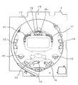
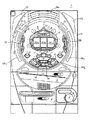
図4は、遊技盤6に設けられる装飾ランプおよび装飾LEDの配置を示す遊技盤6の正面図である。図4を参照して、遊技盤6には、可変表示装置8の内部であって上部左右両側部分にそれぞれ設けられる飾りLED111と、上中央部分に設けられる飾りランプ114と、装飾ランプカバー25の内部に設けられる飾りLED112と、入賞口24の内部に設けられる飾りランプ115と、可変入賞球装置19の内部であって、左右両側部分にそれぞれ設けられる飾りランプ116と中央部分に設けられる飾りランプ113とが配置されている。
【0064】
可変入賞球装置19の内部で左右両側部分に設けられる飾りLED111と、装飾ランプカバー25の内部に設けられる飾りLED112とは、複数のLEDであり、複数のLEDが同時に点灯または消灯する。飾りランプ113〜116は、熱陰極線管であり、白色と赤色のものがある。これらの飾りLED111,112と飾りランプ113〜116とは、後述するランプLED回路60によりON/OFF制御され、点滅する。
【0065】
図5は、遊技制御基板31の基本回路53が遊技制御に用いる各種ランダムカウンタを示す図である。図5には、ランダムカウンタ1〜5の7種類(ランダムカウンタ3は3−1、3−2、3−3の3つからなる)のランダムカウンタが示されている。
【0066】
ランダムカウンタ1は、始動記憶がある場合にその始動記憶に基づく特別図柄の可変表示の結果を大当りとするか否かを決定するために用いられるランダムカウンタである。このランダムカウンタは、タイマ割込毎(具体的には0.002秒毎)に1ずつ加算更新され、0から加算更新されてその上限である299まで加算更新された後再度0から加算更新される。
【0067】
ランダムカウンタ2は、ランダムカウンタ1の値により特別図柄の可変表示の結果を大当りとすることが決定された場合に、可変表示の結果を大当り図柄のうち確率変動図柄とするか否かを決定するために用いられるランダムカウンタである。このランダムカウンタは、タイマ割込毎(具体的には0.002秒毎)に1ずつ加算更新され、0から加算更新されてその上限である5まで加算更新された後再度0から加算更新される。
【0068】
ランダムカウンタ3−1、ランダムカウンタ3−2、ランダムカウンタ3−3は、画像表示領域9に最終的に停止表示される停止図柄(確定図柄)の種類を決定するために用いられるランダムカウンタである。
【0069】
ランダムカウンタ3−1は左図柄決定用であり、0から加算されてその上限である11まで加算されると再度0から加算される。ランダムカウンタ3−1は、タイマ割込毎すなわち0.002秒毎、および、割込処理余り時間毎に1ずつ加算される。
【0070】
ランダムカウンタ3−2は、中図柄決定用のランダムカウンタであり、0から加算されてその上限である11まで加算されると再度0から加算される。ランダムカウンタ3−2は、ランダムカウンタ3−1の桁上げ毎に1ずつ加算される。ランダムカウンタ3−1の桁上げとは、ランダムカウンタ3−1が加算されて11から0となることをいう。
【0071】
ランダムカウンタ3−3は、右図柄決定用のランダムカウンタであり、0から加算されてその上限である11まで加算されると再度0から加算される。ランダムカウンタ3−3は、ランダムカウンタ3−2の桁上げ毎に1ずつ加算される。
【0072】
なお、ランダムカウンタ3−1とランダムカウンタ3−2とによって決定される左図柄と右図柄とが同じ図柄となることにより、表示結果が外れとなるリーチ状態となる。また、ランダムカウンタ1により可変表示の結果を大当りとしないことが決定された場合に、ランダムカウンタ3−1、ランダムカウンタ3−2、およびランダムカウンタ3−3とが同じカウンタ値を示す場合には、ランダムカウンタ3−2のカウンタ値が、1加算されたカウンタ値となる。このように、特別図柄の可変表示の結果を大当りとするか否かはランダムカウンタ1のみによって決定されることになる。
【0073】
ランダムカウンタ4は、リーチ種類を決定するためのランダムカウンタであり、0から加算されてその上限である99まで加算されると再度0から加算される。リーチ種類とは、可変表示装置がリーチ状態となった場合に表示されるリーチ演出動作の種類をいい、たとえば、中図柄を定速度でスクロールさせて中図柄を可変表示するノーマルロング、中図柄を規則的に間欠してスクロールさせて中図柄を可変表示するコマ送り、中図柄を不規則に間欠してスクロールさせて中図柄を可変表示する変則コマ送りなどのリーチ演出動作をいう。ランダムカウンタ4は、タイマ割込毎すなわち0.002秒毎、および、割込処理余り時間毎に1ずつ加算される。
【0074】
ランダムカウンタ5は、ランダムカウンタ1の値により特別図柄の可変表示の結果を大当りとすることが決定された場合に、可変表示の結果表示する大当り図柄を決定するために用いられるランダムカウンタである。このランダムカウンタは、タイマ割込毎(具体的には0.002秒毎)に1ずつ加算更新され、0から加算更新されてその上限である5まで加算更新された後再度0から加算更新される。なお、大当たり図柄は、ランダムカウンタ2の値により、大当たり図柄のうち確率変動図柄または非確率変動図柄のいずれかの図柄の中から決定される。
【0075】
これらのランダムカウンタ1〜5のカウンタ値は、始動口14に入賞した始動入賞玉が始動口スイッチ17で検出されたときにRAM55に記憶される。また、ランダムカウンタ1,2,5(表示結果に影響するもの)は始動口入賞時にRAM55に記憶し、ランダムカウンタ3,4は可変表示開始時に抽出してもよい。このようにすれば、始動保留記憶のためのエリアを小さくすることが可能となる。
【0076】
図6は、ランダムカウンタ3、ランダムカウンタ5、および表示制御コマンドと可変表示装置で表示される図柄との関係を説明するための図である。図中、MODEとEXITとは、表示制御コマンドを示している。表示制御コマンドは、1バイトデータからなるMODEデータと、同じく1バイトデータからなるEXTデータとの計2バイトのデータからなる。このうち、MODEデータは、表示制御データの種別を指定するデータである。一方、EXTデータはMODEデータにより示されたコマンド種別のうち特定の表示制御内容を具体的に指定するデータである。したがって、MODEデータとEXTデータとで1つのコマンドを形成する。具体的には、MODEデータによって、左図柄、中図柄、右図柄のいずれであるかが示され、EXTデータによってそれぞれの図柄が示される。たとえば、MODEデータが「90H」でEXTデータが「00H」の表示コマンドは、左図柄が「0」の図柄であることを示す。
【0077】
大当たり図柄決定用のランダムカウンタ5については、確変判定用のランダムカウンタ2により非確変図柄と判定された場合には、ランダムカウンタ5の値に「0」「2」「4」「6」「8」「A」の図柄がそれぞれ対応する。具体的には、ランダムカウンタ5の値が「0」の場合には図柄「0」が対応し、「1」の場合には図柄「2」が対応し、「2」の場合には図柄「4」が対応し、「3」の場合には図柄「6」が対応し、「4」の場合には図柄「8」が対応し、「5」の場合には図柄「A」が対応する。
【0078】
また、確変判定用のランダムカウンタ2により確変図柄と判定された場合には、ランダムカウンタ5の値に「1」「3」「5」「7」「9」「B」の確変図柄がそれぞれ対応する。具体的には、ランダムカウンタ5の値が「0」の場合には図柄「1」が対応し、「1」の場合には図柄「3」が対応し、「2」の場合には図柄「5」が対応し、「3」の場合には図柄「7」が対応し、「4」の場合には図柄「9」が対応し、「5」の場合には図柄「B」が対応する。
【0079】
ハズレ出目決定用のランダムカウンタ3−1、3−2、3−3(これらをまとめてランダムカウンタ3という)は、ランダムカウンタ3の値に図柄が対応する。具体的には、ランダムカウンタ3の値が「0」の場合には図柄「0」が対応し、
「1」の場合には図柄「1」が対応し、「2」の場合には図柄「2」が対応し、「3」の場合には図柄「3」が対応し、「4」の場合には図柄「4」が対応し、「5」の場合には図柄「5」が対応し、「6」の場合には図柄「6」が対応し、「7」の場合には図柄「7」が対応し、「8」の場合には図柄「8」が対応し、「9」の場合には図柄「9」が対応し、「10」の場合には図柄「A」が対応し、「11」の場合には図柄「B」が対応する。
【0080】
図7は、MODEデータ「80H」によって指定される変動開始コマンドを示す図である。図7を参照して、変動開始コマンドとしては、EXTDATA「00H」〜「07H」によってその表示時間を指定する8種類のコマンドが用意されている。このうち、EXTDATA「00H」に対応する変動開始コマンドは、表示時間が「T1」を示す変動開始コマンドである。すなわち、可変表示装置8が可変開始した後表示結果を導出するまでの時間が「T1」となることを示す。同様に、EXTDATA「01H」に対応する変動開始コマンドが表示時間「T2」を示し、「02H」に対応する変動開始コマンドが表示時間「T3」を、「03H」に対応する変動開始コマンドが表示時間「T4」を、「05H」に対応する変動開始コマンドが表示時間「T4」を、「06H」に対応する変動開始コマンドが表示時間「T5」を、「07H」に対応する変動開始コマンドが表示時間「T6」を示す。T1〜T6の時間は、T1ほど短く、T6ほど長い。
【0081】
可変表示装置が可変開始してから表示結果が導出されるまでの表示動作を変動パターンといい、特にリーチ状態が表示される場合の動作パターンをリーチ変動という。また、左図柄、中図柄、右図柄の順に同じ間隔で停止する変動パターンを通常変動という。通常変動は、リーチ状態が表示される場合の通常変動とリーチ状態が表示されない場合通常変動とがある。すなわち、リーチ変動には、リーチ演出動作とリーチ状態が表示される場合の通常変動とが含まれる。リーチ演出動作については後で詳しく説明する。
【0082】
EXTDATA「00H」に対応する変動開始コマンドは、可変表示装置8の変動パターンが、通常変動であることを示す。EXTDATA「01H」〜「04H」に対応する変動開始コマンドは、変動パターンがリーチ演出動作であり、かつ、表示結果が特定の表示態様とならないことを指定したリーチ変動であることを示す。さらに、EXTDATA「05H」〜「07H」に対応する変動開始コマンドは、変動パターンがリーチ演出動作であり、かつ、表示結果が特定の表示態様となるリーチ変動であることを示す。
【0083】
<遊技制御メイン処理および割り込み処理>
図8は、基本回路53により実行される遊技制御メイン処理および割り込み処理を示すフローチャートである。図8においては、(a)に遊技制御メイン処理が示され、(b)に割り込み処理が示されている。
【0084】
図8の(a)を参照して、遊技制御メイン処理においては、まず、スタックポインタの指定アドレスをセットするためのスタックセット処理が行なわれる(S1)。次いで、初期化処理が行なわれる(S2)。初期化処理では、RAM55にエラーが含まれているか判定され、エラーが含まれている場合には、RAM55を初期化することおよび各種フラグの初期設定などの処理が行なわれる。さらに、初期化処理では、後述する割り込み処理を実行するタイミングを規定するタイマ割り込み時間(たとえば0.002秒)をCPU56に設定する処理がなされる。これにより、電源投入等によるリセット後の最初の割り込み処理の実行タイミング規定のための計時が開始される。
【0085】
次に、停止図柄を決定する等のための表示用乱数更新処理が行なわれる(S3)。このパチンコ遊技機1においては、可変表示装置8の可変表示での特別図柄の停止図柄が乱数(ランダムカウンタのカウンタ値)に基づいて決定される。このS3では、そのように停止図柄を決定するための表示用乱数が更新される。表示用乱数更新処理は、無限ループにより繰返し実行され続けるが、後述する割り込み処理が起動された場合には、表示用乱数更新処理を構成するプログラムのうちの実行中の位置で一時停止され、その割り込み処理が終了すると一時停止したプログラムの位置から実行が再開される。
【0086】
次に、図8の(b)を参照して、割り込み処理は、CPU56により管理されるタイマ割り込み用のタイマの計時値が設定値(S2またはS13で設定されるタイマ割り込み時間)になるごとに実行が開始される。
【0087】
割り込み処理においては、まず、ランプ制御基板35および音声制御基板70に音声発生やLED点灯制御用の所定のコマンドを送信するための処理が行なわれるとともに、情報出力回路64を介してホール管理用コンピュータに大当り情報、始動情報、確率変動情報などのデータを送信するためのデータ出力処理が行なわれる(S4)。次に、パチンコ遊技機1の内部に備えられている自己診断機能によって種々の異常診断をし、その結果に応じて必要ならば警報を発生させるためのエラー処理が行なわれる(S5)。次に、遊技制御に用いられる各種の判定用乱数を示す各ランダムカウンタを更新する判定用乱数更新処理が行なわれる(S6)。
【0088】
次に、特別図柄プロセス処理が行なわれる(S7)。特別図柄プロセス処理では、複数種類の処理のうちの1つが特別図柄プロセスフラグの値に従って選択されて実行される。そして、特別図柄プロセスフラグの値は、遊技状態に応じて各処理中において更新される。次に、普通図柄プロセス処理が行なわれる(S8)。普通図柄プロセス処理では、7セグメントLEDによる普通図柄用可変表示器10を所定の順序で制御するための普通図柄プロセスフラグに従って該当する処理が選び出されて実行される。そして、普通図柄プロセスフラグの値は、遊技状態に応じて各処理中に更新される。
【0089】
次に、ゲートスイッチ12、始動口スイッチ17、Vカウントスイッチ22、カウントスイッチ23等の状態を入力し、各入賞口や可変入賞球装置に対する入賞があったか否か等を判定するスイッチ処理が行なわれる(S9)。始動口スイッチ17により始動入賞が検出された場合には、このスイッチ処理において、始動記憶処理が実行される。具体的には、始動口スイッチ17により始動入賞が検出されると、そのタイミングで大当り判定用のランダムカウンタのカウンタ値が抽出され、始動記憶用の特別図柄判定用バンクにその抽出値が記憶される。これにより始動記憶がなされる。前述したように始動記憶用の特別図柄判定用バンクは、バンク0〜バンク3の4つ構成されており、この4つのバンクによって最大4つの始動記憶を可能にしている。よって、始動入賞が検出された際にすべてのバンクに記憶がある場合には、その始動入賞が無効とされる。
【0090】
次に、S3と同様の表示用乱数更新処理が行なわれる(S10)。次に、賞球基板37との間の入賞球信号処理が行なわれる(S11)。すなわち、基本回路53は、賞球基板37より賞球数要求信号が入力されると、賞球基板37に対して出力すべき賞球コマンド(賞球数指定信号)を選択する。次に、選択した賞球コマンドを出力するための賞球コマンド出力処理が行なわれる(S12)。賞球基板37は、この賞球数指定信号に基づいて玉払出装置97を駆動制御する。
【0091】
次に、タイマ割り込み時間設定処理が行なわれる(S13)。S13においては、前述したようなタイマ割り込み時間(たとえば0.002秒)をS2の場合と同様に設定する処理が実行される。S13の後、この割り込み処理が終了する。これにより、この割り込み処理の終了時にS13によってタイマ割り込み時間が設定され、次の割り込み処理の実行タイミングを規定するための計時が開始されることとなる。したがって、割り込み処理が終了するごとにタイマ割り込みのための時間が計時され、その後タイマ割り込み時間が経過するごとに割り込み処理が実行されることとなる。この割り込み処理が終了すると、前述したメイン処理のプログラムの実行が、一時停止していた位置から再開される。
【0092】
<全体処理>
図9は、本実施の形態におけるパチンコ遊技機1で行なわれる制御の全体的な流れを示すフローチャートである。図9を参照して、始動口14に打玉が入賞して始動口スイッチ17により検出され(ステップS20)、このとき、ランダムカウンタ1〜5のカウンタ値は、RAM55に記憶される。そして、RAM55に記憶されたランダムカウンタ1のカウンタ値をもとに、可変表示装置8の表示結果を大当りとするか否かが判定される(ステップS21)。大当りとする場合には、大当りフラグを設定し(ステップS22)、リミッタ作動か否かを判定する(ステップS23)。
【0093】
ここでリミッタとは、確率変動状態における大当りが予め定められた確変継続回数に達した場合に作動する。これは、予め定められた確変継続回数の大当りが発生するまで確率変動状態に継続制御するために行なう処理である。確率変動状態における大当りが予め定められた確変継続回数を超える場合にはステップS27に進み、そうでない場合にはステップS24に進む。
【0094】
ステップS24では、RAM55に記憶されたランダムカウンタ2のカウンタ値をもとに、高確率当りであるか否かを判断する。たとえば、ランダムカウンタ2のカウンタ値が0〜2のいずれかのときに高確率当りとする。高確率当りと判断した場合には、大当り図柄を確変図柄に決定する(ステップS25)。ステップS24で高確率当りでないとされた場合には、大当り図柄を非確変図柄に決定する(ステップS27)。ステップS25とステップS27においては、ランダムカウンタ2とランダムカウンタ5とのカウンタ値を用いて図6で説明した図柄が決定される。
【0095】
ステップS25の処理の後には、確変当りフラグをセットし(ステップS28)、ステップS28aに進む。ステップS27の後には、ステップS28aに進む。一方、ステップS21で大当りでないと判断された場合には、ステップS26に進み、外れ図柄を決定した後ステップS28aに進む。ステップS26で外れ図柄の決定は、ランダムカウンタ3−1、3−2、3−3のカウンタ値に基づき決定される。
【0096】
ステップS28aでは、後述するリーチパターン決定処理が行なわれステップS28bに進む。ステップS28bでは、音と光の演出パターンが検出される。音と光の演出パターンの検出については後述する。
【0097】
次のステップS29では、可変表示装置8で可変開始させるための変動開始コマンド(変動パターン(別言すれば変動パターンが実行される所定時間)を指定するコマンドを兼用)を送出するとともに、ステップS28bで決定された演出パターンが実行される。そして、確定図柄指定コマンドが送出され(ステップS30)、確定図柄が指定される。ステップS29で指定された所定時間の演出パターンが可変表示装置8で実行され、所定時間が経過すると図柄確定コマンドが表示制御基板80に送出され、表示制御基板80に図柄の確定時期が通知され、可変表示が終了する。
【0098】
ステップS32では、大当りフラグが設定されているか否かが判断され、設定されていない場合には、ステップS33に進みスタート待ちの状態となり、設定されている場合には、ステップS34で確変フラグがクリアされる。ここで確変フラグをクリアするのは、普通図柄の当り確率を高くすること、始動用電動役物15が開成する回数を増加すること、始動用電動役物15の可動片の開成期間を長くすること等の処理を大当り中は行なわないようにするためである。
【0099】
そして、大当りコマンドを可変入賞球装置19に送出し特定遊技状態が終了するのを待つ(ステップS35)。特定遊技状態が終了した時点で、確定図柄が確変図柄であったか否かが判断され(ステップS36)、確変図柄の場合にはステップS37に進み、確変フラグをセットする。確変図柄でない場合には、ステップS37を行なわず、ステップS38に進む。ステップS38では、再度始動口スイッチ17により始動口14に入賞した打玉が検出されるまで待ち状態となるか、保留記憶がある場合には、当該記憶に基づく処理(ステップS21から)が実行される。
【0100】
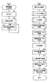
<リーチパターン決定処理>
次に図9のステップS28aで行なわれるリーチパターン決定処理について説明する。図10は、リーチパターン決定処理の流れを示すフローチャートである。図10を参照して、リーチパターン決定処理は、RAM55に記憶されたランダムカウンタ1のカウンタ値をもとに、可変表示装置8の表示結果を大当りとするか否かが判定される(ステップS50)。大当りの場合には、ステップS59に進み、そうでない場合にはステップS51に進む。ステップS59では、大当たり時リーチ用乱数判定値にランダムカウンタ4のカウンタ値が設定される。
【0101】
ステップS51では、ランダムカウンタ3−1とランダムカウンタ3−3とのカウンタ値に基づき右停止図柄と左停止図柄とが参照される(ステップS51)。そして、左停止図柄と右停止図柄とが同じか否かが判断され(ステップS52)、同じでない場合には可変表示装置8の変動パターンを通常変動に設定する(ステップS53)。ステップS52で左停止図柄と右停止図柄とが同じと判断された場合には、リーチ判定値決定テーブルを用いて、保留記憶数と左停止図柄とからリーチ用乱数判定値が決定される(ステップS54)。
【0102】
次のステップS54aでは、確率変動中か否かが判断される。そして、高確率である場合には、高確率時はずれリーチ決定用のリーチ用乱数テーブルが設定される(ステップS54b)。ステップS54aで低確率と判断された場合には(ステップS54aでNO)、低確率時はずれリーチ決定用のリーチ用乱数テーブルが設定される(ステップS55)。そして、ステップS54で設定されたリーチ用乱数判定値が抽出される(ステップS56)。リーチ判定値決定テーブル、高確率時はずれリーチ決定用および低確率時はずれリーチ決定用のそれぞれのリーチ用乱数テーブルについては後述する。
【0103】
そしてランダムカウンタ4のカウンタ値が抽出され、大当りの場合(ステップS50でYES)には大当り時の演出パターン振分けテーブルを用いて、大当りでなく高確率時の場合(ステップS54aでYES)には高確率時はずれリーチ決定用のリーチ用乱数テーブルを用いて、大当りでなく低確率時の場合(ステップS54aでNO)には低確率時はずれリーチ決定用のリーチ用乱数テーブルを用いて、それぞれEXTDATAが決定される(ステップS57)。
【0104】
そして、表示制御用コマンドに、変動開始コマンドを示すMODE(80H)と00H〜07HのうちのいずれかのEXTDATAとが設定される(ステップS58)。その後処理を終了する。
【0105】
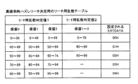
<リーチ判定値決定テーブル>
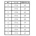
次に、リーチ判定値決定テーブルについて説明する。図11は、リーチ判定値決定テーブルを示す。リーチ判定値決定テーブルは、遊技制御基板31のROMに記憶され、変動コマンドを設定する場合に図10のステップS56で用いられる。図11を参照して、リーチ判定値決定テーブルは、保留記憶数と左図柄(左停止図柄)とからリーチ用乱数判定値を決定するためのテーブルである。リーチ判定値には、「A」で示されるリーチ用乱数判定値1と、「B」で示されるリーチ用乱数判定値2とがある。リーチ用乱数判定値は、保留記憶数と左図柄とが定まれば求まる。たとえば、保留記憶数が「2」のとき(保留数2)で、左図柄が「2」のときには、リーチ判定値は、「B:リーチ用乱数判定値2」とされる。
【0106】
<リーチ用乱数テーブル>
次に、リーチ用乱数テーブルについて説明する。リーチ用乱数テーブルには、高確率時はずれリーチ決定用と低確率時はずれリーチ決定用との2つのリーチ用乱数テーブルがある。リーチ乱数用テーブルは、遊技制御基板31のROMに記憶され、変動コマンドを設定する場合に、高確率時はずれリーチ決定用のリーチ用乱数テーブルが図10のステップS54bで用いられ、低確率時はずれリーチ決定用のリーチ用乱数テーブルが図10のステップS55で用いられる。
【0107】
図12は、高確率時はずれリーチ決定用のリーチ用乱数テーブルを示す図である。図12を参照して、高確率時のはずれリーチ決定用のリーチ用乱数テーブルは、図10のステップS54で求めたリーチ用乱数判定値と、保留記憶数と、ランダムカウンタ4のカウンタ値と、EXTDATAとの関係を示すテーブルである。したがって、リーチ用乱数判定値と保留記憶数とランダムカウンタ4のカウンタ値とが定まれば、EXTDATAが定まることになる。たとえば、図11に示したリーチ判定値決定テーブルで、リーチ用乱数判定値1(A)が設定され、保留記憶数が「2」で、ランダムカウンタ4のカウンタ値が「50」の場合には、EXTDATAは、「01H」に設定され、ランダムカウンタ4のカウンタ値が「80」の場合にはEXTDATAは「03H」に設定される。ここで、リーチ用乱数判定値1(A)の場合に、保留記憶数が0〜2に限られるのは、図11で保留記憶数が「3」(保留数3)の場合には、リーチ用乱数判定値1が設定されることがないからである。
【0108】
図11のリーチ判定値決定テーブルでリーチ用乱数判定値2(B)が設定された場合には、保留記憶数によらず、ランダムカウンタ4のカウンタ値のみによって、EXTDATAが定められる。たとえば、リーチ用乱数判定値2(B)でランダムカウンタ4のカウンタ値が「50」の場合には、EXTDATAは「00H」に設定され、ランダムカウンタ4のカウンタ値が「80」の場合にはEXTDATAは「01H」に設定される。リーチ用乱数判定値2(B)の場合には、「03H」「04H」のEXTDATAは設定されることがない。なお、リーチ用乱数判定値2(B)の場合に、保留記憶数が「0」がないのは、図11において、保留記憶数が「0」(保留数0)の場合にリーチ用乱数判定値2(B)が設定される場合がないからである。
【0109】
ここで、EXTDATAが「00H」に設定された場合には、図8で示したように可変表示装置の変動期間がT1とされ、変動パターンがリーチ演出動作でなく、リーチ状態が表示される場合の通常変動の変動パターンで可変表示動作が行なわれる。
【0110】
図13は、低確率時はずれリーチ決定用のリーチ用乱数テーブルを示す。低確率時はずれリーチ決定用のリーチ用乱数テーブルは、リーチ用乱数判定値、保留記憶数、ランダムカウンタ4のカウンタ値、およびEXTDATAの関係を示すテーブルである。そして、リーチ用乱数判定値、保留記憶数およびランダムカウンタ4のカウンタ値が定まることにより、EXTDATAが定められる。たとえば、図10のステップS54でリーチ用乱数判定値1(A)が設定され、保留記憶数が「2」であり、ランダムカウンタ4のカウンタ値が「50」の場合には、EXTDATAが「02H」に設定され、ランダムカウンタ4のカウンタ値が「80」の場合にはEXTDATAが「03H」に設定される。また、図10のステップS54でリーチ用乱数判定値2(B)が設定された場合には、保留記憶数によらずランダムカウンタ4のカウンタ値のみによってEXTDATAが定められる。たとえば、ランダムカウンタのカウンタ値が「50」の場合にはEXTDATAが「01H」に設定され、ランダムカウンタ4のカウンタ値が「80」の場合にはEXTDATAが「02H」に設定される。ランダムカウンタ4のカウンタ値が「0〜49」の場合にはEXTDATAが「00H」に設定される。EXTDATAが「00H」に設定された場合には、図8で示したように可変表示装置の変動期間がT1とされ、変動パターンがリーチ演出動作でなく、リーチ状態が表示される場合の通常変動の変動パターンで可変表示動作が行なわれる。
【0111】
リーチ用乱数判定値1(A)の場合に保留記憶数が「3」の場合がないのは、保留記憶数が「3」の場合にリーチ用乱数判定値1(A)が設定される場合がないからである。同様に、リーチ用乱数判定値2の場合に保留記憶数が「0」がないのは、保留記憶数が「0」の場合にリーチ用乱数判定値2(B)が設定される場合がないからである。
【0112】
以上説明したように、可変表示装置8がリーチ状態となった場合であっても、EXTDATAが「00H」に設定されて、リーチ演出動作を行なわない通常変動の変動パターンで可変表示される。また、図11と図12または図13で示したようにEXTDATAが「00H」に設定される確率は保留記憶数が多いほど高く、ランダムカウンタ4のカウンタ値に基づき定められる。
【0113】
<大当り時用の演出パターン振分けテーブル>
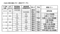
次に、大当り時用の演出パターン振分けテーブルについて説明する。図14は、大当り時の演出パターン振分けテーブルを示す。図14を参照して、大当り時の演出パターン振分けテーブルは、リーチ用乱数、EXTDATA、確定図柄(確変図柄、非確変図柄)、音ランプ、予告、変動パターンの7つの欄から構成されている。リーチ用乱数は、ランダムカウンタ4のカウンタ値を示し、EXTDATAは、ランダムカウンタ4のカウンタ値により定まるEXTDATAを示す。確定図柄は、ランダムカウンタ2とランダムカウンタ5とのカウンタ値に基づき定まる大当り時の確定図柄を示す。ランダムカウンタ2のカウンタ値に基づき確変図柄と非確変図柄とのいずれかが定められ、ランダムカウンタ5のカウンタ値によりそれぞれの図柄が決定される。音ランプは、飾りLED111,112と飾りランプ113〜116で行なわれる発光演出パターンとスピーカ27より発せられる効果音の発音演出パターンとからなる演出パターンを示す。演出パターンには演出0〜演出5の6つのパターンがある。
【0114】
予告とは、可変表示装置が可変開始した後左図柄が表示されるまでの間に、6種類のキャラクタのうちいずれかが可変表示装置8に重畳して表示されることにより、大当りの予告を示す予告パターンである。予告パターンには、キャラクタの種類に応じて予告0〜予告5の6種類のパターンがある。
【0115】
以上、演出0〜演出5と予告0〜予告5は対応づけられて演出される。すなわち、演出2が実行される場合は、予告2を実行するように定められている。この実施の形態では、遊技制御手段が演出0〜5のいずれかを決定し、予告0〜5は表示制御手段が遊技制御手段から直接的に指令を受けることなく、選択決定するが、図14、図15に示される確定時の図柄の組み合わせにより、演出0〜5と予告0〜5の対応付けが可能である。
【0116】
このようにすれば、遊技制御手段が予告0〜5を決定することが不要であり、予告内容に応じて細かく表示コマンドを出力する必要もなくなり、遊技制御手段の表示制御に関する制御負担が軽減される。
【0117】
ここでリーチ演出動作の変動パターンについて詳しく説明する。ノーマルロングとは、左図柄、と右図柄とが停止し、左図柄と右図柄とが同じとなったリーチ状態において、中図柄が所定の時間順方向(上から下方向)にスクロールを継続した後停止するリーチ演出動作をいう。再変動とは、たとえばノーマルロングのリーチ演出動作表示を行なった後、中図柄が停止し、左図柄、中図柄、右図柄がすべて同じとなった状態において、左図柄、中図柄および右図柄が同時に同じ方向に同じスクロールする動作を行なった後、同時に停止するリーチ演出動作をいう。
【0118】
右戻りとは、左図柄が停止し、右図柄が一旦停止した状態では、左図柄と右図柄とが同じ図柄とならず、リーチ状態とはならないが、右図柄が逆方向(下から上方向)にスクロールして左図柄と同じ図柄で停止することによりリーチ状態となるリーチ演出動作をいう。たとえば、右戻りノーマルロングのリーチ演出動作は、左図柄が停止した状態では図柄が「7」であり、その後右図柄が停止して右図柄が「8」となった後、右図柄が逆方向にスクロールして右図柄が「7」となることによりリーチ状態となり、その後、中図柄が所定の期間スクロールした後停止するリーチ演出動作である。
【0119】
コマ送りとは、上述のノーマルロングが左図柄と右図柄とが停止した後、中図柄が所定の時間スクロールした後停止するのに対し、左図柄と右図柄とが停止した後、中図柄がスクロール、停止の動作を繰返す間欠的な動作を行なった後停止するリーチ演出動作をいう。中図柄が間欠的なスクロールを行なう場合には、中図柄がスクロールするたびに図柄が1つずつ順方向にずれる表示態様となる。
【0120】
変速コマ送りとは、上述のコマ送りのリーチ演出動作で中図柄が順方向に間欠的にスクロールする動作であったのに対し、たとえば、逆方向のスクロールを間欠的に行なったり、間欠的なスクロールではあるが1回のスクロールで図柄が2コマ以上ずれるスクロールを行なったりするリーチ演出動作をいう。
【0121】
本実施の形態における可変表示装置8においては、上述したリーチ演出動作を組合せて12種類の変動パターンを可変表示することができる。なお、変動パターンとして12種類を示したが、これに限られるわけではなく、これより少ない変動パターンでもよく、これとは逆にこれより多い変動パターンを用いてもよい。
【0122】
大当り時の時の演出パターン振分けテーブルは、遊技制御基板31のROM54記憶されており、遊技制御基板31で大当り時にEXTDATAを設定する場合に用いられ、ランダムカウンタ4のカウンタ値に基づき変動開始コマンドのEXTDATAが定められる。たとえば、ランダムカウンタ4のカウンタ値が10の場合には、EXTDATAは「05H」に設定される。
【0123】
また、大当り時の演出パターン振分けテーブルは、音ランプの演出パターンを決定する場合にも用いられる。音ランプの演出パターンは、ランダムカウンタ4のカウンタ値と確定図柄とにより定められる。たとえば、ランダムカウンタ4のカウンタ値が10で確定図柄が「B」の場合には演出0の演出パターンに設定される。
【0124】
さらに、大当り時の演出パターン振分けテーブルは表示制御基板に設けられたROMにも記憶されている。そして、表示制御基板で予告パターンと変動パターンを設定する場合にも用いられる。予告パターンと変動パターンとは、EXTDATAと確定図柄とにより定められる。たとえば、EXTDATAが「05H」で確定図柄が「B」の場合には、予告パターンは設定されず、「ノーマルロング再変動」の変動パターンが設定される。
【0125】
また、確定図柄が確変図柄と非確変図柄とのいずれかによって、予告パターンが振分けられる。たとえば、EXTDATAが「00H」の場合であって、確定図柄が確変図柄(1,3,5,7,9,B)の場合には、予告パターンは設定されず、確定図柄が非確変図柄(0,2,4,6,8,A)の場合には、「予告1」の予告パターンが設定される。なお、図では、予告パターンと変動パターンとを別に示しているが、予告パターンは変動パターンに含まれ、変動パターンの一部を構成する。
【0126】
大当たり時は、大当たりとして確定表示される図柄に応じて、演出0〜5および予告0〜5が決定される。なお、予告5、演出5が出現した場合は、確変になり易い等の設定をすることも可能である。また、この実施の形態では、確変だが、時短となる遊技機にあっては、時短図柄、または、その回数に応じて決定してもよい。
【0127】
<はずれ時の演出パターン振分けテーブルの説明>
図15は、はずれ時の演出パターン振分けテーブルを示す。図15を参照して、はずれ時の演出パターン振分けテーブルは、EXTDATAと、確定時図柄の組合せずれコマ数と、音ランプと、予告と、変動パターンとの5つの欄から構成される。EXTDATAは、変動開始コマンドにおける変動時刻を示すEXTDATAである。確定時図柄の組合せずれコマ数とは、リーチ状態となる場合は、表示結果が右図柄と左図柄とが同じ図柄となり、中図柄が右図柄および左図柄と異なるので、中図柄と右図柄および左図柄とのコマのずれ数をいう。リーチ状態とならない場合には、右図柄と左図柄が異なる図柄となるので、右図柄と左図柄のコマのずれ数をいう。音ランプとは、発音演出パターンおよび発光演出パターンの組合せからなる演出パターンを示す。
【0128】
はずれ時の演出パターン振分けテーブルは、遊技制御基板31のROM54に記憶され、音ランプの演出パターンを決定する場合に用いられる。音ランプの演出パターンは、EXTDATAと確定時図柄組合せずれコマ数とにより定められる。たとえば、EXTDATAが「01H」で左図柄および右図柄と中図柄とのコマのずれ数が±1であれば演出2の演出パターンとなる。
【0129】
また、はずれ時の演出パターン振分けテーブルは、表示制御基板80に設けられるROMにも記憶される。そして、表示制御基板80で、予告と変動パターンとが定められる。たとえば、EXTDATAが「01H」で確定時図柄組合せずれコマ数が±1の場合には、予告2の予告パターンと右戻りノーマルショートの変動パターンとが設定される。
【0130】
以上説明したように本実施の形態におけるパチンコ遊技機においては、保留記憶数が多いときには可変表示時間の短い動作パターンとなる確率が高くなり、保留記憶数が少ないときには可変表示時間の長い動作パターンとなる確率が高くなる。また、可変表示装置8がリーチ状態となった場合に、保留記憶数が多いときにはリーチ演出動作を行なわない通常変動の動作パターンとなる確率が高くなり、保留記憶数が少ないときにはリーチ演出動作の動作パターンとなる確率が高くなる。保留記憶数が多い場合は、その保留記憶を速く消化することができ、保留記憶数が少ない場合にはリーチ演出により遊技者を楽しませることができる。さらに、保留記憶数によって、リーチ状態が大当りとなりやすいものと大当りになり難いものとを設けるようにすれば、リーチ状態により大当りとなる期待度を変えることができる。
【0131】
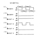
図16は、表示制御コマンドの出力タイミングと左中右図柄の変動と音ランプの演出との関係を説明するためのタイミングチャートである。特別図柄の変動を開始させる際には、最初に、MODEデータ「80H」により指定される変動開始コマンド「80H ××H」が遊技制御基板31から表示制御基板80に対して出力される。なお、「80H ××H」は、図7に示した「80H 00H」〜「80H 07H」のうちのいずれかのコマンドである。この変動開始コマンドが表示制御基板80に受信されたタイミングで、特別図柄の一斉変動が開始される。なお、前述したように変動開始コマンドの種類によりリーチの有無および可変表示期間が指定されている。表示制御基板80はその指令に基づいてリーチの演出内容や大当り予告演出の有無等を決定する。
【0132】
その後、変動開始コマンドが出力されることによって特別図柄の一斉変動が開始されてから所定時間が経過すると、遊技制御基板31から表示制御基板80に対して左中右図柄に対応する3つの確定図柄指定コマンドが順に出力される。図には、左図柄用の確定図柄指定コマンド1「90H ××H」、中図柄用の確定図柄指定コマンド2「91H ××H」、および右図柄用の確定図柄指定コマンド3「92H ××H」がその順で出力されることが示されている。なお、「××H」は、図6に示した「00H」〜「0BH」のうちのいずれかである。表示制御基板80側ではこの確定図柄指定コマンド基づいて最終的に表示結果として導出表示する確定図柄の種類が決定される。
【0133】
各図柄の変動パターンとしては、たとえば、加速変動から高速変動を経て低速変動に至り、揺れ変動を経て確定図柄を停止表示させるパターンがしめされている。図示するタイミングチャートでは左図柄が最初に低速変動から揺れ変動に切換えられ、続いて右図柄、中図柄の順で低速変動から揺れ変動に切換えられている。また、加速変動の途中でキャラクタあるいは背景の変更などによる演出方法によって、所定の予告(大当り予告やリーチ予告等)表示がなされている。さらに、右図柄が高速変動から低速変動に切換えられた段階から各種のリーチ演出のための表示が開始されている。
【0134】
図柄の一斉変動が開始されてから、変動開始コマンドにより指定される変動時間Tnが経過した時点で、図柄確定コマンドが遊技制御基板31から出力される。これにより、図柄の揺れ変動が終了し、確定図柄が停止表示される。
【0135】
音ランプの演出パターンは、図柄の一斉変動の開始と同時に、演出0〜5のいずれかの演出パターンが開始される。そして、右図柄が低速変動に切換えられた段階で、可変表示装置の変動パターンに対応した演出パターンが行なわれる。すなわち、変動パターンがリーチ演出動作であれば、リーチ演出動作に対応した演出パターンを実行し、通常変動であれば通常変動に対応した演出パターンを実行する。
【0136】
以上、図16を用いて説明したように、遊技制御基板31側から表示制御基板80に対しては、特別図柄の変動に関し、「変動開始時期」、「確定図柄」、「図柄確定時期」の3種類の情報のみが出力される。表示制御基板80は、このうち変動開始コマンドと確定図柄指定コマンドに従い、リーチ演出の内容や予告の有無などを独自に決定する。
【0137】
また、可変表示装置8を可変開始させるタイミングで変動開始コマンドが出力され、表示結果を導出表示させるタイミングで図柄確定コマンドが出力されるために、それらのコマンドによって、表示制御基板80側の表示制御用CPU101は、可変開始時期と表示結果を導出表示させる時期とを特定できる。さらに、変動開始コマンドには可変表示期間やリーチの有無等の変動パターンを特定可能なデータが含まれており、そのコマンドによって表示制御用CPU101は可変開始時期に加えて、変動パターンをも特定できる。
【0138】
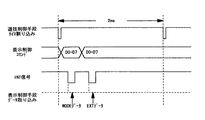
図17は、表示制御コマンドデータの出力タイミングと表示制御基板80側の表示制御コマンドのデータ取込タイミングとを説明するためのタイミングチャートである。前述したように、遊技制御基板31の基本回路53側のタイマ割込時間は2msとされている。このタイマ割込時間2msの期間において表示制御コマンドが出力される。
【0139】
まず、基本回路53はタイマ割込に伴って1バイト(D0〜D7)のMODEデータの出力を開始し、INT信号を無効状態から有効状態に切換える。表示制御基板80側では、INT信号が無効状態から有効状態に切換えられたタイミングでMODEデータの取込が行なわれる。その後、所定時間が経過すればINT信号が有効状態から無効状態に切換えられる。続いて、1バイト(D0〜D7)のEXTデータの出力が開始され、INT信号が所定の待機時間だけ無効状態となった後、有効状態に切換えられる。表示制御基板80側では、この有効状態に切換えられたタイミングにおいてEXTデータの取込が行なわれる。
【0140】
このように、遊技制御基板31の基本回路53は、表示制御基板80に対して連続的に同一の表示制御コマンドデータを繰返して出力するのではなく、所定の待機時間を設けるなどして表示制御基板80側のデータの受信性能を考慮し、表示制御コマンドデータを表示制御基板80側が認識可能な態様で1回のみ出力する。これにより、基本回路53が表示制御基板80に表示制御コマンドデータを出力する際の処理負担を軽減できる。
【0141】
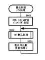
<表示制御メイン処理>
図18は、表示制御基板80の表示制御用CPU101が実行する表示制御メイン処理を説明するためのフローチャートである。表示制御メイン処理においては、まず、RAM101a、I/O、VDPなどをイニシャライズする処理が実行される(S601)。続いて、INT割込処理が実行される(S602)。次に、表示用乱数更新処理1が実行される(S603)。表示用乱数更新処理1が実行されることにより、表示制御用の乱数の加算更新がなされる。次に、前記S602に処理が移行し、S602およびS603の処理が繰返し実行される。
【0142】
図19は、タイマ割込処理を説明するためのフローチャートである。タイマ割込は、たとえば2msごとに発生する。この2msごとに発生するタイマ割込の際に、図示するタイマ割込処理が実行され、表示制御がなされる。タイマ割込処理においては、まず、表示制御プロセス処理が実行される(S701)。表示制御プロセス処理は、表示制御特別図柄プロセスフラグの値に応じ、画像表示領域9に各種表示を行なう処理である。詳細については、図20を用いて後述する。
【0143】
次に、表示用乱数更新処理2が実行され(S702)、表示制御用の乱数の加算更新の加算更新がなされる。
【0144】
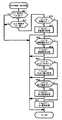
図20は、表示制御プロセス処理を説明するためのフローチャートである。表示制御プロセス処理においては、まず、コマンド受信完了フラグが設定されているか否かが判断される(S901)。コマンド受信完了フラグがセットされていない場合には、処理が終了する。コマンド受信完了フラグがセットされている場合には、コマンド受信中フラグがあるか否かが判断される(S902)。コマンド受信中フラグがある場合には処理が終了するが、コマンド受信中フラグがない場合には、受信されたコマンドの内容がS903、S905、S907、およびS909で判断される。
【0145】
すなわち、変動開始コマンドであると判断された場合(S903でYES)には、特別図柄プロセスフラグの値が変動表示処理を実行できる値に更新され(S904)、処理が終了する。ここで更新される変動表示処理とは、受信された変動開始コマンドと確定図柄指定コマンドとから、図14に示した大当たり時の演出パターン振分けテーブルまたは図15に示したはずれ時の演出パターン振分けテーブルをとに基づき決定された予告パターンと変動パターンとを表示制御するための処理である。
【0146】
受信されたコマンドの内容が図柄確定コマンドであると判断された場合(S905でYES)には、特別図柄プロセスフラグの値が図柄確定処理を実行できる値に更新され(S906)、処理が終了する。受信されたコマンドの内容が大当り中コマンドであると判断された場合(S907でYES)には、特別図柄プロセスフラグの値が大当り表示処理を実行できる値に更新され(S908)、処理が終了する。
【0147】
受信されたコマンドの内容が表示画面コマンドであると判断された場合(S909でYES)には、特別図柄プロセスフラグの値が表示画面処理を実行できる値に更新され(S910)、処理が終了する。
【0148】
受信されたコマンドが変動開始コマンドでも図柄確定コマンドでもなく、大当り中コマンドでも表示画面コマンドでもないと判断された場合には、特別図柄プロセスフラグの値がエラー表示処理を実行できる値に更新され(S911)、処理が終了する。なお、S911で特別図柄プロセスフラグの値が更新される場合とは、受信されたコマンドが制御不能なコマンド(たとえばデータ化け)である場合である。
【0149】
<発光演出動作の説明>
次に発光演出パターンについて説明する。図21〜図24は、飾りLED111,112と飾りランプ113〜116の発光演出パターンを説明するための図である。図21は、発光演出パターンaにおける飾りLEDおよび飾りランプの発光タイミングを示すタイミングチャートである。図21を参照して、飾りLED111は、消灯と点灯を256[ms]間隔で繰返し行なう。なお図中、点灯している状態をONで示し、消灯している状態をOFFで示している。飾りLED112は、時間の経過にかかわらず消灯した状態となる。飾りランプ113は、時間の経過にかかわらず点灯した状態となる。飾りランプ116は、点灯と消灯を256[ms]間隔で繰返し行なう。また、飾りLED111が消灯しているときに飾りランプ116が点灯し、飾りLED111が点灯しているときに飾りランプ116が消灯する。飾りランプ115,114は、時間の経過にかかわらず消灯した状態となる。なお、図では1024[ms]の期間で発光演出パターンaを示したが、発光演出パターンaは、1024[ms]間だけ行なうのではなく、このパターンを繰返し行なう。そして、後述する演出パターンの演出期間の間繰返し行なうことになる。
【0150】
図22は、発光演出パターンa2における飾りLEDおよび飾りランプの発光タイミングを示すタイミングチャートである。発光演出パターンa2は、上述の右戻りのリーチ演出動作において行なわれ、右図柄が右戻り動作を開始したときから停止するまでに行なわれる発光演出パターンである。図22を参照して、飾りLED111,112は、点灯と消灯を128[ms]間隔で繰返し行なう。飾りLED111が点灯しているときに飾りLED112は消灯し、飾りLED111が消灯しているときに飾りLED112は点灯する。飾りランプ113は、時間の経過にかかわらず点灯した状態となる。飾りランプ116,115は、点灯と消灯を128[ms]間隔で繰返し行なう。飾りランプ116が点灯しているときに飾りランプ115は消灯し、飾りランプ116が消灯しているときに飾りランプ115は点灯する。また、飾りLED111が点灯しているときに飾りランプ116が点灯し、飾りLED111が消灯しているときに飾りランプ116が消灯する。飾りランプ114は、時間の経過にかかわらず点灯した状態となる。
【0151】
図23は、発光演出パターンbにおける飾りLEDおよび飾りランプの発光タイミングを示すタイミングチャートである。図23を参照して、飾りLED111,112と飾りランプ113〜116とは、点灯と消灯を128[ms]間隔で繰返し行なう。飾りLED111と飾りランプ114,115が消灯しているときに飾りLED112と飾りランプ113,116とが点灯し、飾りLED111と飾りランプ114,115とが点灯しているときに飾りLED112と飾りランプ113,116とが消灯する。
【0152】
図24は、発光演出パターンcにおける飾りLEDおよび飾りランプの発光タイミングを示すタイミングチャートである。図24を参照して、飾りLED111,112と飾りランプ113,115,116とは、256[ms]間隔で点灯と消灯を繰返し行なう。飾りLED111と飾りランプ115とが消灯しているときに飾りLED112と飾りランプ113,116とが点灯し、飾りLED111と飾りランプ115とが点灯しているときに飾りLED112と飾りランプ113,116とが消灯する。飾りランプ114は、時間の経過にかかわらず消灯した状態となる。
【0153】
このように、飾りLED111,112と飾りランプ113〜116とは、4種類の発光演出パターン(a,a2,b,c)で、点灯または消灯することにより、光による演出を表現することができる。これにより、光による演出を遊技者の視覚に訴えることができる。
【0154】
<発音演出動作の説明>
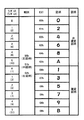
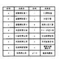
図25は、スピーカ27より発せられる効果音を説明するための図である。図25を参照して、効果音には、記号a〜o,p1、p2に対応付けられた17種類がある。記号aに対応する効果音は、可変表示装置8の左中右図柄が停止した状態からスクロールを開始するとき(変動開始時)に発生される第1の音を示す変動開始音1である。記号bに対応する効果音は、左中右図柄の変動開始時に発生される第2の音を示す変動開始音2である。記号cに対応する効果音は、左中右図柄の変動開始時に発生される第3の音を示す変動開始音3である。記号dに対応する効果音は、左図柄がスクロールした状態から停止したときに発生される音を示す左図柄停止音である。記号eに対応する効果音は、中図柄がスクロールした状態から停止したときに発生される音を示す中図柄停止音である。記号fに対応する効果音は、右図柄がスクロールした状態から停止したときに発生される音を示す右図柄停止音である。
【0155】
記号gに対応する効果音は、リーチ演出動作が右戻りのときに、右図柄が逆方向(下から上方向)にスクロールするときに発生される音を示す右図柄逆変動である。記号hに対応する効果音は、右図柄がスクロールした状態から停止した状態となったときに発生される音であって、本実施の形態では左図柄、中図柄、右図柄の順で停止するため右図柄の停止音を変えることでリーチになるときの演出に変化をもたらすことが可能であり、記号d〜記号fに対応する効果音とは異なる音を示す特殊停止音である。記号iに対応する効果音は、左図柄と右図柄ドラム100cとが停止して左図柄と右図柄とが同じ図柄となってリーチ状態となったときに発生される音を示すリーチ開始音である。
【0156】
記号jに対応する効果音は、リーチ演出動作においてコマ送りの演出動作が行なわれるときに発生される音を示すコマ送り音である。記号kに対応する効果音は、リーチ演出動作が変則コマ送りとなったときに発生される音を示す変速コマ送り音である。記号lに対応する効果音は、リーチ演出動作がスーパーコマ送りとなったときに発生される音を示すスーパーコマ送り音である。
【0157】
記号mに対応する効果音は、左中右図柄がスクロール中に、左図柄、中図柄、および右図柄が同じとなり、かつ、左中右図柄が同期してスクロールする全回転のリーチ演出動作となったときに発生される音を示す全回転開始音である。記号nに対応する効果音は、全回転のリーチ演出動作が開始され、その後半で発生される音を示す全回転後半音である。
【0158】
記号oに対応する効果音は、リーチ演出動作が再変動となったとき、その再変動の開始時に発生される音を示す確変抽選開始音である。記号p1,記号p2に対応する効果音は、リーチ演出動作が再変動となったときに、再変動のリーチ演出動作の間発生される音を示す確変抽選音である。確変抽選音には、p1とp2との2種類がある。
【0159】
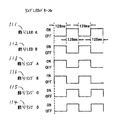
図26は、発光演出パターンと発音演出パターンとを組合せた演出パターンを示す図である。図26を参照して、演出パターンには演出0〜演出8の9種類がある。演出0〜演出8のそれぞれの演出パターンは、発光演出パターンと発音演出パターンとの組合せからなる。発光演出パターンは、上述の発光演出パターンa〜cで示した4種類の発光演出パターンの中からいずれか1つが選ばれる。発音演出パターンは、記号a〜cで示した変動開始音のうちのいずれかと、記号f,hで示した右図柄停止音のいずれかとの組合せ、または、記号p1,p2で示した確変抽選音のいずれかである。たとえば、演出0の演出パターンは、発光演出パターンaと、記号aの変動開始音1および記号fの右図柄の停止音からなる発音演出パターンとの組合せからなる。また、演出1の発光演出パターンは、リーチ演出動作が右戻りとなるときの演出パターンを示し、リーチ演出動作が右戻りとなるまでは発光演出パターンaで演出され、リーチ演出動作が右戻りとなったときに発光演出パターンa2で演出される発光演出パターンと、記号aの変動開始音1および記号fの右図柄停止音からなる発音演出パターンとの組合せからなる。また、演出6,7,8は、リーチ演出動作が再変動となったときの演出パターンである。たとえば、演出6の演出パターンは、発光演出パターンaと、記号p1の発音演出パターンとの組合せである。このように、演出0〜8の9つの演出パターンは、発光演出パターンと発音演出パターンとの組合せが異なるので、遊技者は、視覚あるいは聴覚で演出パターンを区別することができる。また、可変表示装置8による変動パターンとの組み合わせが複数通りあるので、遊技の演出が限定されない多様な演出が可能となる。さらに、可変表示装置8による変動パターンと整合された演出パターンが決定されるので、整合のとれた演出が可能となる。
【0160】
[第2の実施の形態]
図27は、第2の実施の形態におけるパチンコ遊技機1の正面図である。なお、第1の実施の形態と同一または相当する部材については同一の番号を付し、説明は省略する。図27を参照して、第2の実施の形態におけるパチンコ遊技機1は、額縁状に形成されたガラス扉枠2を有する。このガラス扉枠2の後方には、遊技盤6が着脱自在に取付けられている。また、ガラス扉枠2の下部表面には打球供給皿3がある。打球供給皿3の下部には、打球供給皿3から溢れた玉を貯留する余剰玉受皿4と、遊技者が打球操作するための操作ノブ5とが設けられている。操作ノブ5を遊技者が操作することにより、打球供給皿3内に貯留されているパチンコ玉を1個ずつ発射することができる。遊技領域7の中央には、識別情報の一例となる特別図柄を可変開始させる可変表示装置8が設けられている。この可変表示装置8には、打玉の通過ゲート11の通過に伴って普通図柄が可変表示される普通図柄用の可変表示器10と、始動記憶表示器18とが設けられている。さらに、可変表示装置8の下方には、始動口14が構成された始動用電動役物15と、開閉板20の傾動により打玉の入賞可能な開放状態となる可変入賞球装置19とが設けられている。始動用電動役物15には、可動片が左右に設けられている。また、一般入賞口として、可変表示装置8の上部や、可変入賞球装置19の左右に入賞口24がそれぞれ設けられている。また、26は、打込まれた打玉がいずれの入賞口や可変入賞球装置にも入賞しなかった場合にアウト玉として回収するアウト口であり、25は、装飾ランプカバーである。
【0161】
遊技領域7の外周には枠ランプとしての遊技効果LED28aおよび遊技効果ランプ28b,28cと、賞球の払出し時に点灯する賞球ランプ51と、玉切れ中に点灯するランプ玉切れランプ52とが設けられており、遊技領域7の上部の左右にはステレオ音の音声などの効果音を発生するためのスピーカ27,27が設けられている。
【0162】
可変表示装置8は、中央の表示領域9に複数種類の特別図柄を可変表示可能な3つのドラム100a,100b,100cを備える。始動入賞が発生したことを条件として、3つのドラムが回転することにより、複数種類の特別図柄が上から下に向かってスクロール表示される。その後、所定時間が経過してドラムの回転が停止して可変表示が終了した結果、大当り図柄のゾロ目が予め複数種類定められた当りラインのうちのいずれかに揃って表示されれば大当りとなる。大当りとなれば、可変入賞球装置19の開閉板20が傾動して大入賞口が開口する。これにより、打玉を大入賞口に入賞させることが可能な遊技者にとって有利な第1の状態に制御され、遊技状態が遊技者にとって有利な特定遊技状態(大当り状態)となる。
【0163】
普通図柄用表示器10は緑色と赤色の2つのLEDで構成されている。普通図柄用表示器10の表示結果が緑色のLEDが点灯すれば「当り」となり、赤色のLEDが点灯すれば「ハズレ」となる。
【0164】
図28は、遊技盤6に設けられる装飾ランプおよび装飾LEDの配置を示す遊技盤6の正面図である。図28を参照して、遊技盤6には、可変表示装置8の内部であって上部左右両側部分にそれぞれ設けられる飾りLED111と、装飾ランプカバー25の内部に設けられる飾りLED112と、可変表示装置8のの内部にそれぞれに設けられる4つの白色の飾りランプ113と3つの赤色の飾りランプ114と、入賞口24の内部に設けられる飾りランプ115と、可変入賞球装置19の内部であって左右両側部分にそれぞれ設けられる飾りランプ116とが配置されている。飾りランプ113,114は、上から白赤白赤白赤白の順に白色と赤色とが交互に配列されている。そして、赤色の飾りランプ114は、ドラム100a〜100cが停止したときにドラム100a〜100cの側面に描かれた図柄が停止する位置(図中でハッチングで示す上中下の3ヵ所)に対応して設けられ、停止した図柄を裏面から照射できる位置に配置されている。
【0165】
可変入賞球装置19の内部で左右両側部分に設けられる飾りLED111は、複数のLEDであり、複数のLEDが同時に点灯または消灯する。装飾ランプカバー25の内部に設けられる飾りLED112は、複数のLEDであり、複数のLEDが同時に点灯または消灯する。
【0166】
入賞口24の内部に設けられる飾りランプ115は、ランプである。可変入賞球装置19の内部で左右両側部分にそれぞれ設けられる飾りランプ116は、複数のランプである。これらの飾りLED111,112と飾りランプ113〜116とは、ランプLED回路60によりON/OFF制御され、点滅する。
【0167】
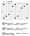
図29〜34は、飾りランプ113,114の発光演出パターンを示す図である。図29は、発光演出パターン1における飾りランプ113,114の発光タイミングを示す図である。図29を参照して、それぞれの枠には、ドラム100a内に設けられた飾りランプ113,114(図中で左列)と、ドラム100b内に設けられる飾りランプ113,114(図中で中列)と、ドラム100c内に設けられる飾りランプ113,114(図中で右列)とが示されている。左列、中列、右列に示す飾りランプ113,114は、点線で示す四角の枠がそれぞれの飾りランプ113,114を示している。そして、左列、中列および右列のそれぞれにおいて、飾りランプ113と飾りランプ114とが上から順に交互に配列されている。
【0168】
図29のそれぞれの枠は、ある時点における飾りランプ113,114の発光状態を示し、黒色で塗りつぶした部分の飾りランプ113,114が発光していることを示す。そして、枠の左上に付した番号の順に発光状態が推移する。1つの枠で示す発光状態が継続される期間は、たとえば256[ms]とされる。
【0169】
発光演出パターン1においては、まず、ドラム100a内の1番目と2番目の飾りランプ113のみが発光し、他の飾りランプ113,114は発光しない(発光状態(1))。次の発光状態(2)は、ドラム100a内の2番目と3番目の飾りランプ113のみが発光し、他の飾りランプ113,114は発光しない。次の発光状態(3)は、ドラム100a内の3番目と4番目の飾りランプ113のみが発光し、他の飾りランプ113,114は発光しない。次の発光状態(4)は、ドラム100aの4番目の飾りランプ113と、ドラム100bの4番目の飾りランプ113のみが発光し、他の飾りランプ113,114は発光しない。次の発光状態(5)では、ドラム100b内の4番目の飾りランプ113と、ドラム100c内の4番目の飾りランプ113のみが発光し、他の飾りランプ113,114は発光しない。次の発光状態(6)では、ドラム100c内の3番目と4番目の飾りランプ113のみが発光し、他の飾りランプ113,114は発光しない。
【0170】
このように発光状態を推移させながら、最後の発光状態(12)では、すべての飾りランプ113,114が消灯する。発光状態(1)から発光状態(12)までの状態の推移を繰返し行なうことにより発光演出パターン1が構成される。
【0171】
図30は、発光演出パターン2における飾りランプ113,114の発光状態の推移を示す図である。発光演出パターン2では、まず最初の発光状態(1)として、ドラム100a〜100c内のすべての飾りランプ113が発光する。次の発光状態(2)では、ドラム100a内の3つの飾りランプ114のみが発光し、他の飾りランプ113,114は発光しない。次の発光状態(3)では、ドラム100a〜100c内のすべての飾りランプ113が発光し、飾りランプ114は発光しない。そして次の発光状態(4)では、ドラム100b内の3つの飾りランプ114が発光し、他の飾りランプ113,114は発光しない。そして次の発光状態(5)では、ドラム100a〜100c内の飾りランプ113のみが発光し、飾りランプ114は発光しない。次の発光状態(6)では、ドラム100c内の3つの飾りランプ114が発光し、他の飾りランプ113,114は発光しない。そして、6種類の発光状態を繰返し行なうことで発光演出パターン2が構成される。
【0172】
図31は発光演出パターン3における飾りランプ113,114の発光状態を示す図である。図32は、発光演出パターン4における飾りランプ113,114の発光状態を示す図である。図33は、発光演出パターン5における飾りランプ113,114の発光状態を示す図である。図34は、発光演出パターン6〜9における飾りランプ113,114の発光状態を示す図である。図34を参照して、発光演出パターン6における飾りランプ113,114の発光状態は、6つの発光状態を繰返して行なうことにより構成されている。発光演出パターン7では、ドラム100a〜100cがすべて回転して全図柄が変動しているときには、ドラム100a〜100c内のすべての飾りランプ113をすべて発光させ、飾りランプ114を発光させない発光状態とする。そして、次の発光状態(2)では、ドラム100aが回転を停止する直前でドラム100a内の飾りランプ114を発光させない状態とする。このとき、発光しているのはドラム100b,100c内の飾りランプ113のみとなる。
【0173】
発光演出パターン8における飾りランプ113,114の発光状態は、まず、ドラム100a〜100c内のすべての飾りランプ113を発光させ、飾りランプ114は発光させない(発光状態(1))。そして次の発光状態(2)は、ドラム100aが停止するタイミングの手前で100a内の飾りランプ113を消灯する。そして次の発光状態(3)では、ドラム100cが停止するタイミングの手前でドラム100c内の飾りランプ113を消灯させる。このとき、ドラム100b内の飾りランプ113のみが点灯している状態となる。
【0174】
発光演出パターン9における飾りランプ113,114の発光状態は、まず、ドラム100a〜100cがすべて回転して全図柄が変動しているときは、ドラム100a〜100c内のすべての飾りランプ113を点灯した状態とする。そして次の発光状態は、ドラム100aが停止するタイミングの手前でドラム100a〜100c内のすべての飾りランプ113を消灯する。このとき発光している飾りランプ113,114はない。このようにした場合には、100%リーチ演出動作が行なわれるようにする。これにより、遊技者は、ドラム100aが回転を停止し、左図柄が表示された段階で、リーチとなることを知ることができ、遊技者の大当りとなる期待感を向上させることができる。
【0175】
次に、以上説明した実施の形態の変形例や特徴点を以下に列挙する。
(1) 可変開始コマンドは、可変表示期間がすべて異なるように構成したが、可変表示期間が同じとなるようにしてもよい。この場合には、変動開始コマンドは、変動パターンを変動開始コマンドの数に分類したコマンドとして取り扱うようにすればよい。
【0176】
(2) 本実施の形態におけるパチンコ遊技機1では、可変表示装置8で可変開始させた後表示結果が導出表示されるまでの可変表示動作期間において演出パターンに基づく音と光による演出を行なうようにしたが、可変表示装置8が可変表示動作をしていない期間に音と光による演出を行なうようにしてもよい。たとえば、第2の実施の形態におけるパチンコ遊技機において、可変表示装置が可変表示動作をしていない期間には、ドラム100a,100b,100cは停止した状態となっている。ドラム100a〜100cが停止した状態で、内部に設けられた飾りランプ113,114による発光演出パターンに基づく演出をさせるようにしてもよい。これにより、可変表示装置が可変表示動作をしていない期間においても、可変表示装置8で光による演出を行なうことができ、遊技者を退屈させることがない。
【0177】
(3) リーチ状態とは、可変表示装置が可変開始された後表示制御が進行して表示結果が導出表示される前段階にまで達した時点でも、前記特定の表示態様となる表示条件から外れていない表示態様をいう。可変表示装置8の可変表示中においては、リーチ状態が発生する場合がある。ここで、リーチとは、表示状態が変化可能な可変表示装置を有し、該可変表示装置が時期を異ならせて複数の表示結果を導出表示し、該複数の表示結果が予め定められた特定の表示態様の組合せとなった場合に、遊技状態が遊技者にとって有利な特定遊技状態となる遊技機において、前記複数の表示結果の一部がまだ導出表示されていない段階で、既に導出表示されている表示結果が前記特定の表示態様の組合せとなる条件を満たしている表示状態をいう。また、別の表現をすれば、リーチとは、表示状態が変化可能な可変表示部を複数有する可変表示装置の表示結果が予め定められた特定の表示態様の組合せになった場合に、遊技状態が遊技者にとって有利な特定遊技状態となる遊技機において、前記可変表示装置の表示結果がまだ導出表示されていない段階で、前記特定の表示態様の組合せが表示されやすい可変表示態様となったと遊技者に思わせるための表示状態をいう。そして、たとえば、前記特定の表示態様の組合せが揃った状態を維持しながら複数の前記可変表示部による可変表示を行なう状態もリーチ表示状態に含まれる。さらにリーチの中には、それが出現すると、通常のリーチに比べて、大当りが発生しやすいものがある。このような特定のリーチをスーパーリーチという。
【0178】
なお、リーチ状態とは、可変表示装置の表示制御が進行して表示結果が導出表示される前段階にまで達した時点での表示状態であって、前記表示結果が導出表示される以前に決定されている前記複数の可変表示部の表示結果の少なくとも一部が前記特定の表示態様となる条件を満たしている場合の表示状態をもいう。
【0179】
(4) 表示結果決定手段が決定した表示結果がリーチ状態となる条件を満たしている場合にリーチ演出動作を行なうか否かを決定するためのリーチ演出表示実行決定手段を設け、前記リーチ演出表示実行決定手段は、前記可変表示装置8に導出される表示結果に応じて異なる複数の確率でリーチ演出動作を行なうか否かを決定するようにしてもよい。
【0180】
(5) 前記表示結果決定手段は、遊技状態を遊技者に有利な特定遊技状態とするか否かを事前に決定する特定遊技状態事前決定手段を含み、前記リーチ演出表示実行決定手段は、特定遊技状態事前決定手段が特定遊技状態とすることを決定した場合には、特定遊技状態としないことを決定した場合よりも高い確率でリーチの実行を決定するようにしてもよい。
【0181】
(6) 前記リーチ演出表示実行決定手段は少なくとも遊技者に不利な通常遊技状態中に、可変表示装置でリーチの演出動作を行なうか否かを決定するようにしてもよい。
【0182】
(7) リーチ演出表示を複数種類の中から選択するリーチ種類選択手段を設け、前記リーチ演出表示実行決定手段は、数値を更新する数値更新手段の数値に応じてリーチの種類を選択するとともに、前記リーチ種類選択手段は、前記数値更新手段の数値を用いてリーチ種類を選択するようにしてもよい。
【0183】
(8) 図2に示されるように表示制御基板80を遊技制御基板31と別に設け、遊技制御基板31から表示制御基板80に表示制御コマンド(変動コマンドと確定図柄コマンド)を入力するようにした。これと同様に、ランプ・LED回路60を遊技制御基板31と別に設け、遊技制御基板31から表示制御コマンドと同様のコマンドをランプ・LED回路60と音声制御基板70とに入力し、ランプ・LED回路60と音声制御基板70とでそれぞれ独立して音または光の演出パターンを決定するようにしてもよい。
【0184】
(9) 今回開示された実施の形態はすべての点で例示であって制限的なものではないと考えられるべきである。本発明の範囲は上記した説明ではなくて特許請求の範囲によって示され、特許請求の範囲と均等の意味および範囲内でのすべての変更が含まれることが意図される。
【0185】
【課題を解決するための手段の具体例】
(1) 図1等に示される可変表示装置8により、表示状態が変化可能な可変表示装置が構成される。図1等に示されるパチンコ遊技機1により、前記可変表示装置の表示結果が特定の表示態様となった場合に遊技者にとって有利な特定遊技状態に制御可能な遊技機が構成されている。
図2等に示される遊技制御基板31により、前記遊技機の遊技状態を制御する遊技制御手段が構成されている。図1等に示されるスピーカ27と飾りLED112、113および飾りランプ114〜116により、遊技状態に応じて音と光りによる演出を行なう演出手段が構成されている。図2等に示される表示制御基板80により、前記可変表示装置を可変表示させた後表示結果を導出表示させる制御を行なう可変表示制御手段が構成されている。図2等に示される音声制御基板70とランプLED回路60により、前記演出手段を制御させる演出制御手段が構成されている。
【0186】
図9のステップS25、ステップS26またはステップS27で左中右図柄を決定する遊技制御基板30により、前記可変表示装置の表示結果を決定するための表示結果決定手段が構成されている。図10のステップS57でEXTDATAを決定する遊技制御基板30により、前記可変表示装置の可変表示内容を決定するための可変表示内容決定手段が構成されている。
【0187】
表示制御基板80に、図9のステップS29で変動開始コマンドを送出し、ステップS30で確定図柄指定コマンドを送出する遊技制御基板31により、前記表示結果を特定する表示結果コマンドと前記可変表示内容を特定する表示内容コマンドとを前記可変表示制御手段に出力する遊技制御手段が構成されている。
【0188】
図20のステップS904で、変動開始コマンドと確定図柄指定コマンドとに基づき変動パターンを決定して可変表示装置を表示制御する表示制御基板80により、前記表示内容コマンドのみからは特定されない表示演出である特定表示ファクタを、前記表示結果コマンドと前記表示内容コマンドとの組合わせを基に導き出す特定表示ファクタ導出手段が構成されている。図9のステップ29で音ランプ演出を実行する遊技制御基板31により、前記可変表示内容決定手段の決定内容のみからは特定されない演出内容である特定演出ファクタを、前記表示結果決定手段の決定内容と前記可変表示内容決定手段の決定内容との組合わせを基に導き出す特定演出ファクタ導出手段が構成されている。図14に示す大当たり時の演出パターン振分けテーブル、図15に示すハズレ時演出パターン振分けテーブルを用いて変動パターンおよび音ランプの演出パターンを決定することにより、前記特定表示ファクタと前記特定演出ファクタとは、互いに所定の対応関係を有するように決定される構成が示される。
【0189】
(2) EXTDATAが「00H」以外の場合に、図15に示すはずれ時演出パターン振分けテーブルに基づき音ランプの演出パターンと変動パターンとが決定されることにより、決定された前記表示結果が特定の表示態様と異なる場合、決定された前記表示結果が前記特定の表示態様と近似している第1の非特定表示態様の場合と前記第1の非特定表示態様より前記特定の表示態様と近似していない第2の非特定表示態様の場合とで、前記可変表示制御手段は特定表示ファクタの表示に関わる制御を異ならせ、前記演出制御手段は特定演出ファクタの演出に関わる制御を異ならせる構成が示される。
【0190】
(3) 図6に示す図柄により複数の識別情報が構成され、図1または図27に示す可変表示装置により、複数の識別情報を可変表示可能な可変表示部が構成されている。図15に示すはずれ時演出パターン振分けテーブルに基づき、音ランプの演出パターンと変動パターンとが決定されることにより、決定された前記表示結果が特定の表示態様と異なる場合、前記複数の可変表示部で表示される識別情報が近似している第1の非特定表示態様の場合と前記第1の非特定表示態様より前記識別情報が近似していない第2の非特定表示態様の場合とで、前記可変表示制御手段は特定表示ファクタの表示に関わる制御を異ならせ、前記演出制御手段は特定演出ファクタの演出に関わる制御を異ならせる構成が示される。
【0191】
(4) EXTDATAが「00H」以外の場合に、図15に示すはずれ時演出パターン振分けテーブルに基づき音ランプの演出パターンと変動パターンとが決定されることにより、決定された前記表示結果がリーチ態様で特定の表示態様と異なる場合、リーチ態様を構成する識別情報と他の識別情報とが近似している第1の非特定表示態様の場合と前記第1の非特定表示態様より近似していない第2の非特定表示態様の場合とで、前記可変表示制御手段は特定表示ファクタの表示に関わる制御を異ならせ、前記演出制御手段は特定演出ファクタの演出に関わる制御を異ならせる構成が示される。
【0192】
(5) 大当たり時は図14に示す大当たり時演出パターン振分けテーブルに基づき、はずれ時は図15に示すはずれ時演出パターン振分けテーブルに基づいて、音ランプの演出パターンと変動パターンとが決定されることにより、前記特定演出ファクタと前記特定表示ファクタとは、前記可変表示装置の表示結果が特定の表示態様となる期待度に関連して導き出される構成が示されている。
【0193】
(6) 通常時(通常遊技状態)に比べて大当りが発生する確率が高く変動した確率変動状態により、特定遊技状態とは別の遊技者にとって有利な特別遊技状態が構成されている。可変表示装置8に表示された大当りの結果が特定の確変図柄(たとえば数字図柄の「7」)により構成されるものである場合に、その大当りに基づく特定遊技状態の終了後に確率変動状態に制御する遊技機により、前記可変表示装置の表示結果が特別の表示態様となった場合に、前記特定遊技状態とは別の遊技者にとって有利な特別遊技状態に制御可能な遊技機が構成されている。図14に示す大当たり時演出パターン振分けテーブルでEXTDATAが「00H」の場合に変動パターンと音ランプの演出パターンが決定されることにより、前記可変表示装置の表示結果が前記特別の表示態様となるか否かに関連して導き出される前記特定演出ファクタと前記特定表示ファクタとが構成されている。大当たり時は図14に示す大当たり時演出パターン振分けテーブルに基づき、はずれ時は図15に示すはずれ時演出パターン振分けテーブルに基づいて、音ランプの演出パターンと変動パターンとが決定されることにより、前記特定演出ファクタと前記特定表示ファクタとは、前記可変表示装置の表示結果が特定の表示態様となるか否かに関連して導き出される構成が示されている。
【0194】
(7) 図9のステップS29で遊技制御基板30が表示制御基板80に送出する変動開始コマンドにより、前記可変表示装置で可変開始してから表示結果を導出表示するまでの時間を指令対象とする前記可変表示内容が構成されている。
【0195】
(8) 図9のステップS31で図柄確定コマンドを送出することにより、前記可変表示装置で表示結果を導出表示するタイミングで、表示結果を導出表示する変動終了を指令対象とする変動終了指令を前記可変表示制御手段に出力する遊技制御手段が構成されている。図16に示されるように音ランプの演出パターンが図柄確定コマンドの出力タイミングに合わせて終了することにより、前記変動終了指令の出力に関連して特定されるタイミングにしたがって前記演出手段の演出制御を終了する演出制御手段が構成されている。
【0196】
【課題を解決するための手段の具体例の効果】
請求項1に記載の発明によれば、次のような効果を得ることができる。前記遊技制御手段は、前記可変表示装置の表示結果を決定するための表示結果決定手段と、前記可変表示装置の可変表示内容を決定するための可変表示内容決定手段とを含み、前記可変表示装置の可変表示が開始するタイミングで前記表示結果を特定する表示結果コマンドと前記可変開始から表示結果を導出表示するまでの時間を含む可変表示内容を特定する表示内容コマンドとを出力するとともに、可変表示装置の表示結果を導出表示するタイミングで可変表示終了コマンドを出力し、前記可変表示制御手段は、可変表示終了コマンドの出力されるタイミングで可変表示装置の表示結果が導出表示されるとともに、前記表示内容コマンドのみからは特定されない表示演出である特定表示ファクタを、前記表示結果コマンドと前記表示内容コマンドとの組合わせを基に導き出す特定表示ファクタ導出手段を含むので、遊技制御手段から可変表示制御手段へ出力するコマンドの数を減らすことができる。
【0197】
また、前記演出制御手段は、前記表示内容コマンドのみからは特定されない演出内容である特定演出ファクタを、前記表示結果コマンドと前記表示内容コマンドとの組合わせを基に導き出す特定演出ファクタ導出手段を含み、前記特定表示ファクタと前記特定演出ファクタとは、互いに所定の対応関係を有するように決定されるので、前記可変表示制御手段で表示制御される特定表示ファクタと前記演出制御手段で制御される特定演出ファクタとのタイミングおよび内容が整合されたものとすることができる。
【図面の簡単な説明】
【図1】 第1の実施の形態におけるパチンコ遊技機1およびこれに対応して設置されたカードユニット50の正面図である。
【図2】 遊技制御基板31における回路構成の一例を示すブロック図である。
【図3】 表示制御基板80内の回路構成を、画像表示を実現するCRT82とともに示すブロック図である。
【図4】 遊技盤6に設けられる装飾ランプおよび装飾LEDの配置を示す遊技盤6の正面図である。
【図5】 遊技制御基板31の基本回路53が遊技制御に用いる各種ランダムカウンタを示す図である。
【図6】 ランダムカウンタ3、ランダムカウンタ5、および表示制御コマンドと可変表示装置で表示される図柄との関係を説明するための図である。
【図7】 MODEデータ「80H」によって指定される変動開始コマンドを示す図である。
【図8】 基本回路53により実行される遊技制御メイン処理および割り込み処理を示すフローチャートである。
【図9】 本実施の形態におけるパチンコ遊技機1で行なわれる制御の全体的な流れを示すフローチャートである。
【図10】 リーチパターン決定処理の流れを示すフローチャートである。
【図11】 リーチ判定値決定テーブルを示す。
【図12】 高確率時はずれリーチ決定用のリーチ用乱数テーブルを示す図である。
【図13】 低確率時はずれリーチ決定用のリーチ用乱数テーブルを示す。
【図14】 大当り時の演出パターン振分けテーブルを示す。
【図15】 はずれ時の演出パターン振分けテーブルを示す。
【図16】 表示制御コマンドの出力タイミングと左中右図柄の変動と音ランプの演出との関係を説明するためのタイミングチャートである。
【図17】 表示制御コマンドデータの出力タイミングと表示制御基板80側の表示制御コマンドのデータ取込タイミングとを説明するためのタイミングチャートである。
【図18】 表示制御基板80の表示制御用CPU101が実行する表示制御メイン処理を説明するためのフローチャートである。
【図19】 タイマ割込処理を説明するためのフローチャートである。
【図20】 表示制御プロセス処理を説明するためのフローチャートである。
【図21】 発光演出パターンaにおける飾りLEDおよび飾りランプの発光タイミングを示すタイミングチャートである。
【図22】 発光演出パターンa2における飾りLEDおよび飾りランプの発光タイミングを示すタイミングチャートである。
【図23】 発光演出パターンbにおける飾りLEDおよび飾りランプの発光タイミングを示すタイミングチャートである。
【図24】 発光演出パターンcにおける飾りLEDおよび飾りランプの発光タイミングを示すタイミングチャートである。
【図25】 スピーカ27より発せられる効果音を説明するための図である。
【図26】 発光演出パターンと発音演出パターンとを組合せた演出パターンを示す図である。
【図27】 第2の実施の形態におけるパチンコ遊技機1の正面図である。
【図28】 遊技盤6に設けられる装飾ランプおよび装飾LEDの配置を示す遊技盤6の正面図である。
【図29】 発光演出パターン1における飾りランプ113,114の発光タイミングを示す図である。
【図30】 発光演出パターン2における飾りランプ113,114の発光状態の推移を示す図である。
【図31】 発光演出パターン3における飾りランプ113,114の発光状態の推移を示す図である。
【図32】 発光演出パターン4における飾りランプ113,114の発光状態の推移を示す図である。
【図33】 発光演出パターン5における飾りランプ113,114の発光状態の推移を示す図である。
【図34】 発光演出パターン6〜9における飾りランプ113,114の発光状態を示す図である。
【符号の説明】
1はパチンコ遊技機、7は遊技領域、8は可変表示装置、11は通過ゲート、14は始動口、15は始動用電動役物、19は可変入賞球装置、20は開閉板、24は入賞口、25は装飾ランプカバー、27はスピーカ、31は遊技制御基板、60はランプLED回路、70は音声制御基板、80は表示制御基板、100a〜100cはドラム、111,112は飾りLED、113〜116は飾りランプ。[0001]
BACKGROUND OF THE INVENTION
The present invention relates to a gaming machine represented by, for example, a pachinko gaming machine or a coin gaming machine.
[0002]
[Prior art]
In addition to a variable display device whose display state can be changed, what is conventionally known as this type of gaming machine, in order to produce a gaming effect, the production is performed by sound and light according to the gaming state There is a gaming machine that includes control means and can be controlled to a specific gaming state advantageous to the player when the display result of the variable display device is in a specific display mode. In this gaming machine, speakers, LEDs, and the like are used as production means. Then, after the variable display device starts variably and before the display result is derived and displayed, the variable display device produces an effect display with a predetermined operation pattern, and a sound or light with a predetermined effect pattern is produced by an effect means such as a speaker or LED. A predetermined production is performed. A plurality of operation patterns and production patterns are provided, and by combining these, various productions appealing to the player's vision and hearing are possible.
[0003]
[Problems to be solved by the invention]
However, in this type of conventional gaming machine, in order to perform various effects, the number of combinations of operation patterns and effect patterns increases. For this reason, in order to produce an effect in which the operation pattern and the production pattern are matched, it is necessary to control the variable display device and the production means in a consistent manner. As a result, there has been a problem that the number of control commands for controlling the variable display device and the rendering means increases and the control becomes complicated.
[0004]
The present invention has been made to solve the above-described problems, and one of the objects of the present invention is to provide a variety of effects by matching the variable display device and the rendering means, and the variable display device and the rendering means. It is an object of the present invention to provide a gaming machine that can be easily controlled.
[0005]
[Means for Solving the Problems]
According to one aspect of the present invention to achieve the above-mentioned object, the invention according to
Game control means for controlling the gaming state of the gaming machine;
Directing means for performing effects by sound and light according to the gaming state;
Variable display control means for performing control for deriving and displaying a display result after variably displaying the variable display device;
Production control means for controlling the production means,
The game control means includes
Display result determining means for determining a display result of the variable display device;
Variable display content determination means for determining variable display content including time from variable start of the variable display device to display and display a display result,
When the variable display of the variable display device starts Outputting a display result command for specifying the display result and a display content command for specifying the variable display content, and outputting a variable display end command at a timing for deriving and displaying the display result of the variable display device,
The variable display control means includes
A specific display factor deriving means for deriving a specific display factor that is a display effect not specified only from the display content command based on a combination of the display result command and the display content command;
The display result of the variable display device is derived and displayed at the timing when the variable display end command is output,
The production control means includes
A specific effect factor deriving means for deriving a specific effect factor that is an effect content not specified only from the display content command based on a combination of the display result command and the display content command;
At the timing when the variable display end command is output, the effect control of the effect means is ended,
The specific display factor and the specific effect factor are determined so as to have a predetermined correspondence relationship with each other.
[0006]
According to a second aspect of the present invention, in addition to the configuration of the first aspect of the invention, when the determined display result is different from a specific display mode, the determined display result is different from the specific display mode. The variable display control means in the case of the approximate first non-specific display mode and the case of the second non-specific display mode that is not approximated to the specific display mode from the first non-specific display mode. Varies the control related to the display of the specific display factor, and the effect control means changes the control related to the effect of the specific effect factor.
[0007]
According to a third aspect of the invention, in addition to the configuration of the first aspect of the invention, the variable display device includes a plurality of variable display units that can variably display a plurality of identification information.
When the determined display result is different from a specific display mode, the first non-specific display mode and the first non-specific display mode in which identification information displayed on the plurality of variable display units is approximate In the second non-specific display mode in which the identification information is not approximated, the variable display control means changes control related to the display of the specific display factor, and the effect control means is used to produce the specific effect factor. It is characterized by different control.
[0008]
According to a fourth aspect of the present invention, in addition to the configuration of the first aspect of the invention, the variable display device includes a plurality of variable display units capable of variably displaying a plurality of identification information.
When the determined display result is different from the specific display mode in the reach mode, the first non-specific display mode in which the identification information constituting the reach mode and other identification information are approximated and the first In the case of the second non-specific display mode that is not approximated by the non-specific display mode, the variable display control means changes control related to the display of the specific display factor, and the effect control means is used to produce the specific effect factor. It is characterized by different control.
[0009]
According to a fifth aspect of the present invention, in addition to the configuration of the first aspect of the invention, the specific effect factor and the specific display factor are expected degrees in which a display result of the variable display device becomes a specific display mode. It is derived in relation to
[0010]
According to a sixth aspect of the present invention, in addition to the configuration of the first aspect of the present invention, the gaming machine is configured such that when the display result of the variable display device is in a special display mode, the specific gaming state is Can be controlled to a special gaming state that is advantageous to another player,
The specific effect factor and the specific display factor are derived in relation to whether or not the display result of the variable display device is in the special display mode.
[0011]
According to a seventh aspect of the invention, in addition to the configuration of the first aspect of the invention, the variable display content is variably started by the variable display device until the display result is derived and displayed. This time is used as a command target.
[0012]
According to an eighth aspect of the invention, in addition to the configuration of the invention according to any one of the first to seventh aspects, the game control means displays the display result at a timing for deriving and displaying the display result on the variable display device. A variable end command for commanding a variable end to be derived and displayed is output to the variable display control means,
The effect control means ends the effect control of the effect means according to the timing specified in relation to the output of the change end command.
[0013]
[Action]
According to the first aspect of the present invention, the operation is as follows. The game state of the gaming machine is controlled by the action of the game control means. Due to the action of the production means, the production of sound and light is performed according to the gaming state. By the function of the variable display control means, control is performed so that the display result is derived and displayed after the variable display device is variably displayed. The production means is controlled by the action of the production control means. The display result of the variable display device is determined by the function of the display result determining means. The variable display content determination means determines the variable display content including the time from the variable start of the variable display device until the display result is derived and displayed. The display result determining means and the variable display content determining means are included in the game control means. By the action of the game control means, When the variable display on the variable display device starts Display result command for specifying display results and display content command for specifying variable display contents are output. Is At the same time, a variable display end command is output at a timing for deriving and displaying the display result of the variable display device.
[0014]
Due to the function of the specific display factor derivation means included in the variable display control means, the specific display factor which is a display effect that is not specified only from the display content command is derived based on the combination of the display result command and the display content command. It is. By the action of the variable display control means, the display result of the variable display device is derived and displayed at the timing when the variable display end command is output. By the action of the specific production factor deriving means included in the production control means, table Indication command The specific production factor, which is the production content that is not specified only by the command And before Table Indication command Derived based on the combination. The effect control of the effect means ends at the timing when the variable display end command is output. The specific display factor and the specific effect factor are determined so as to have a predetermined correspondence with each other.
[0022]
DETAILED DESCRIPTION OF THE INVENTION
Hereinafter, a pachinko gaming machine as an example of the gaming machine according to the present invention will be described in detail with reference to the drawings. In the following embodiments, a pachinko gaming machine is shown as an example of a gaming machine, but the present invention is not limited to this, and may be, for example, a coin gaming machine or a slot machine.
[0023]
[First Embodiment]
FIG. 1 is a front view of a
[0024]
The
[0025]
When the player inserts a prepaid card in which the card balance is recorded into the card insertion slot 155, the card balance recorded in the prepaid card is read. Next, when the player performs a predetermined ball lending operation, the balance for the lending unit amount set in advance is reduced, and the hit ball for the lending unit amount is supplied to the
[0026]
The
[0027]
The
[0028]
A frame lamp (
[0029]
The
[0030]
A
[0031]
The first state of the variable winning
[0032]
A
[0033]
The hit ball that has entered the
[0034]
The normal
[0035]
The start winning ball won in the start opening 14 is detected by a start opening switch 17 provided on the
[0036]
When the jackpot result displayed on the
[0037]
Therefore, when no restriction is placed on the continuous control of the probability variation state, the probability variation state continues indefinitely at least as long as the big hit that has reached the number of times of the probability change continues is the probability change big hit. In the case of this
[0038]
In the probability variation state, the probability of hitting the normal symbol increases, and the variable display period (variation time) from when the normal symbol variable display starts until the display result is derived and displayed is shortened. Further, in the probability variation state, the number of times the starter electric component 15 is opened from the normal symbol hit increases from 1 to 2, and the opening period of one time increases from 0.2 seconds to 1.4 seconds. Extended.
[0039]
FIG. 2 is a block diagram illustrating an example of a circuit configuration in the
[0040]
The winning
[0041]
A ball dispensing device 97 and a
[0042]
The
[0043]
The
[0044]
The
[0045]
The
[0046]
The
[0047]
The
[0048]
The lamp /
[0049]
A command, which is an example of command information, is transmitted from the
[0050]
The commands transmitted from the
[0051]
The command transmitted from the
[0052]
The
[0053]
The
[0054]
The
[0055]
More specifically, for example, 15 prize balls are paid out for each winning ball for the winning ball that has won the big winning gate of the variable winning
[0056]
In order to control the payout of such three types of prize balls, the
[0057]
The prize ball number signal sent from the
[0058]
FIG. 3 is a block diagram showing a circuit configuration in the
[0059]
Specifically, a command corresponding to the display control command data is given to the
[0060]
FIG. 3 shows a reset circuit 83 for resetting the
[0061]
The
[0062]
In addition, the part that outputs display control on the
[0063]
FIG. 4 is a front view of the
[0064]
The
[0065]
FIG. 5 is a diagram showing various random counters used by the
[0066]
The
[0067]
The
[0068]
The random counter 3-1, the random counter 3-2, and the random counter 3-3 are random counters that are used to determine the type of stop symbol (definite symbol) that is finally stopped and displayed in the
[0069]
The random counter 3-1 is for determining the left symbol. When the random counter 3-1 is added from 0 and added up to 11 which is the upper limit, the random counter 3-1 is added again from 0. The random counter 3-1 is incremented by 1 every timer interruption, that is, every 0.002 seconds, and every interruption processing surplus time.
[0070]
The random counter 3-2 is a random counter for medium symbol determination. When the random counter 3-2 is added from 0 and is added up to 11 which is the upper limit thereof, it is added again from 0. The random counter 3-2 is incremented by one for each carry of the random counter 3-1. The carry of the random counter 3-1 means that the random counter 3-1 is added and becomes 11 to 0.
[0071]
The random counter 3-3 is a random counter for determining the right symbol. When the random counter 3-3 is added from 0 and is added up to 11 which is the upper limit thereof, the random counter is added from 0 again. The random counter 3-3 is incremented by one for each carry of the random counter 3-2.
[0072]
In addition, when the left symbol and the right symbol determined by the random counter 3-1 and the random counter 3-2 are the same symbol, a reach state in which the display result is disengaged is entered. Further, when it is determined by the
[0073]
The
[0074]
The
[0075]
The counter values of these
[0076]
FIG. 6 is a diagram for explaining the relationship between the
[0077]
When the
[0078]
In addition, when the probability counter is determined by the
[0079]
The random counters 3-1, 3-2, and 3-3 for losing appearance determination (collectively referred to as random counter 3) have a symbol corresponding to the value of the
In the case of “1”, the symbol “1” corresponds, in the case of “2” the symbol “2” corresponds, in the case of “3” the symbol “3” corresponds, and in the case of “4” The symbol “4” corresponds to “5”, the symbol “5” corresponds to “5”, the symbol “6” corresponds to “6”, and the symbol “7” corresponds to “7”. ”,“ 8 ”corresponds to symbol“ 8 ”,“ 9 ”corresponds to symbol“ 9 ”,“ 10 ”corresponds to symbol“ A ”, In the case of “11”, the symbol “B” corresponds.
[0080]
FIG. 7 is a diagram showing a change start command specified by the MODE data “80H”. Referring to FIG. 7, eight types of commands for specifying the display time by EXTDATA “00H” to “07H” are prepared as change start commands. Among these, the change start command corresponding to EXTDATA “00H” is a change start command indicating the display time “T1”. That is, the time until the display result is derived after the
[0081]
The display operation from when the variable display device starts variably until the display result is derived is referred to as a variation pattern, and particularly, the operation pattern when the reach state is displayed is referred to as reach variation. A variation pattern that stops at the same interval in the order of left symbol, middle symbol, and right symbol is called normal variation. The normal fluctuation includes normal fluctuation when the reach state is displayed and normal fluctuation when the reach state is not displayed. That is, the reach variation includes a reach effect operation and a normal variation when the reach state is displayed. The reach production operation will be described in detail later.
[0082]
The change start command corresponding to EXTDATA “00H” indicates that the change pattern of the
[0083]
<Game control main processing and interrupt processing>
FIG. 8 is a flowchart showing game control main processing and interrupt processing executed by the
[0084]
Referring to (a) of FIG. 8, in the game control main process, first, a stack setting process for setting a designated address of the stack pointer is performed (S1). Next, initialization processing is performed (S2). In the initialization process, it is determined whether an error is included in the
[0085]
Next, a display random number update process for determining a stop symbol is performed (S3). In the
[0086]
Next, referring to (b) of FIG. 8, the interrupt process is performed every time the timer value for the timer interrupt managed by the
[0087]
In the interruption process, first, a process for transmitting a predetermined command for generating a sound or controlling the LED lighting to the
[0088]
Next, a special symbol process is performed (S7). In the special symbol process, one of a plurality of types of processing is selected and executed according to the value of the special symbol process flag. The value of the special symbol process flag is updated during each process according to the gaming state. Next, a normal symbol process is performed (S8). In the normal symbol process, a corresponding process is selected and executed in accordance with a normal symbol process flag for controlling the normal
[0089]
Next, switch processing is performed to input the states of the
[0090]
Next, a display random number update process similar to S3 is performed (S10). Next, winning ball signal processing with the winning
[0091]
Next, a timer interrupt time setting process is performed (S13). In S13, a process for setting the timer interruption time (for example, 0.002 seconds) as described above is performed in the same manner as in S2. After S13, this interrupt process ends. As a result, at the end of this interrupt process, the timer interrupt time is set by S13, and the timing for defining the execution timing of the next interrupt process is started. Therefore, the time for timer interruption is counted every time the interruption process is completed, and the interruption process is executed every time the timer interruption time elapses thereafter. When this interrupt process is completed, the execution of the main process program described above is resumed from the position where it was temporarily stopped.
[0092]
<Overall processing>
FIG. 9 is a flowchart showing an overall flow of control performed in the
[0093]
Here, the limiter is activated when the jackpot in the probability fluctuation state reaches a predetermined number of times of probability variation. This is a process performed to continuously control the probability variation state until a jackpot of a predetermined number of probability variation continues. If the big hit in the probability fluctuation state exceeds a predetermined number of probability variation continuations, the process proceeds to step S27, and if not, the process proceeds to step S24.
[0094]
In step S24, based on the counter value of the
[0095]
After the process of step S25, a probability variation flag is set (step S28), and the process proceeds to step S28a. After step S27, the process proceeds to step S28a. On the other hand, if it is determined in step S21 that the game is not a big hit, the process proceeds to step S26, and after the off symbol is determined, the process proceeds to step S28a. In step S26, the missing symbol is determined based on the counter values of the random counters 3-1, 3-2, and 3-3.
[0096]
In step S28a, a reach pattern determination process described later is performed, and the process proceeds to step S28b. In step S28b, a sound and light effect pattern is detected. The detection of the sound and light effect pattern will be described later.
[0097]
In the next step S29, a variable start command (variable pattern (in other words, a command for specifying a predetermined time during which the variable pattern is executed) for starting variable by the
[0098]
In step S32, it is determined whether or not the big hit flag is set. If it is not set, the process proceeds to step S33 to wait for a start, and if it is set, the probability variation flag is cleared in step S34. Is done. Here, the probability variation flag is cleared by increasing the probability of hitting a normal symbol, increasing the number of times the starter electric accessory 15 is opened, and lengthening the opening period of the movable piece of the starter electric accessory 15. This is because the processing such as this is not performed during the big hit.
[0099]
Then, the jackpot command is sent to the variable winning
[0100]
<Reach pattern determination process>
Next, the reach pattern determination process performed in step S28a of FIG. 9 will be described. FIG. 10 is a flowchart showing the flow of reach pattern determination processing. Referring to FIG. 10, in the reach pattern determination process, it is determined based on the counter value of
[0101]
In step S51, the right stop symbol and the left stop symbol are referred to based on the counter values of the random counter 3-1 and the random counter 3-3 (step S51). Then, it is determined whether or not the left stop symbol and the right stop symbol are the same (step S52). If they are not the same, the variation pattern of the
[0102]
In the next step S54a, it is determined whether the probability is changing. If the probability is high, a reach random number table for determining reach is set when the probability is high (step S54b). If it is determined in step S54a that the probability is low (NO in step S54a), a reach random number table for determining reach is set when the probability is low (step S55). Then, the reach random number determination value set in step S54 is extracted (step S56). The reach determination value determination table, the reach random number table for determining the reach reach when the probability is high, and the reach random number table for determining the reach reach when the probability is low are described later.
[0103]
Then, the counter value of the
[0104]
Then, MODE (80H) indicating a change start command and EXTDATA among 00H to 07H are set in the display control command (step S58). Thereafter, the process ends.
[0105]
<Reach determination value determination table>
Next, the reach determination value determination table will be described. FIG. 11 shows a reach determination value determination table. The reach determination value determination table is stored in the ROM of the
[0106]
<Reach random number table>
Next, the reach random number table will be described. The reach random number tables include two reach random number tables for determining the reach reach at high probability and for determining the reach reach at low probability. The reach random number table is stored in the ROM of the
[0107]
FIG. 12 is a diagram illustrating a reach random number table for determining the reach reach when there is a high probability. Referring to FIG. 12, the reach random number table for determining the outlier reach at the time of high probability includes the reach random number determination value obtained in step S54 of FIG. 10, the number of reserved memories, the counter value of
[0108]
When reach random number determination value 2 (B) is set in the reach determination value determination table of FIG. 11, EXTDATA is determined only by the counter value of
[0109]
Here, when EXTDATA is set to “00H”, the variation period of the variable display device is T1, as shown in FIG. 8, and the variation pattern is not a reach effect operation but a reach state is displayed. The variable display operation is performed with the fluctuation pattern of the normal fluctuation.
[0110]
FIG. 13 shows a reach random number table for determining reach reach when the probability is low. The reach random number table for determining out-of-range reach reach is a table showing the relationship among the reach random number determination value, the number of reserved storage, the counter value of the
[0111]
In the case of the reach random number determination value 1 (A), there is no case where the reserved memory number is “3”. The case where the reach random number determination value 1 (A) is set when the reserved memory number is “3”. Because there is no. Similarly, in the case of the reach random
[0112]
As described above, even when the
[0113]
<Direction pattern distribution table for big hits>
Next, the effect pattern distribution table for the big hit will be described. FIG. 14 shows an effect pattern distribution table at the time of big hit. Referring to FIG. 14, the effect pattern distribution table at the time of big hit is composed of seven columns of reach random number, EXTDATA, definite symbol (probability variation symbol, non-probability variation symbol), sound lamp, notice, and variation pattern. The reach random number indicates the counter value of the
[0114]
The notice means that one of the six types of characters is displayed superimposed on the
[0115]
As described above, the
[0116]
In this way, it is not necessary for the game control means to determine the
[0117]
Here, the variation pattern of the reach effect operation will be described in detail. In normal long, the left symbol and the right symbol are stopped, and the left symbol and the right symbol are the same in the reach state, the middle symbol continues to scroll in the predetermined time forward direction (from top to bottom). Reach production operation that stops afterwards. For example, after a normal long reach effect is displayed, the left symbol, middle symbol, and right symbol are the same when the left symbol, middle symbol, and right symbol are all the same. A reach effect operation that simultaneously stops in the same direction and then stops simultaneously.
[0118]
Return to the right means that when the left symbol is stopped and the right symbol is temporarily stopped, the left symbol and the right symbol are not the same symbol, and the reach state is not reached, but the right symbol is reversed (from bottom to top) ) To reach the reach state by stopping at the same symbol as the left symbol. For example, when the left design is stopped, the reach effect of normal return to normal long is “7”. After the right design stops and the right design is “8”, the right design is in the reverse direction. This is a reach effect operation in which the right symbol becomes “7” and the reach state is reached, and then the middle symbol scrolls for a predetermined period and then stops.
[0119]
Frame advance means that the normal symbol is stopped after the left symbol and the right symbol are stopped after the middle symbol is scrolled for a predetermined time, while the middle symbol is stopped after the left symbol and the right symbol are stopped. A reach effect operation that stops after an intermittent operation that repeats scrolling and stopping operations. When the middle symbol is intermittently scrolled, each time the middle symbol is scrolled, the symbols are shifted one by one in the forward direction.
[0120]
The shift frame advance is an operation in which the middle symbols are intermittently scrolled in the forward direction in the above-described frame advance reach effect operation. For example, the reverse scroll is intermittently performed or the intermittent symbols are intermittently moved. Although it is a scroll, it means a reach effect operation in which a symbol is shifted by two or more frames in one scroll.
[0121]
In the
[0122]
The effect pattern distribution table at the time of big hit is stored in the
[0123]
The effect pattern distribution table at the time of big hit is also used when determining the effect pattern of the sound lamp. The effect pattern of the sound lamp is determined by the counter value of the
[0124]
Further, the effect pattern distribution table at the time of big hit is also stored in a ROM provided on the display control board. It is also used when setting a notice pattern and a variation pattern on the display control board. The notice pattern and the variation pattern are determined by EXTDATA and a fixed symbol. For example, when EXTDATA is “05H” and the confirmed symbol is “B”, the notice pattern is not set and the variation pattern of “normal long re-variation” is set.
[0125]
Further, the notice pattern is assigned depending on whether the definite symbol is a probability variation symbol or a non-probability variation symbol. For example, when EXTDATA is “00H” and the confirmed symbol is a probability variable symbol (1, 3, 5, 7, 9, B), the notice pattern is not set and the confirmed symbol is a non-probable variable symbol ( In the case of 0, 2, 4, 6, 8, A), a notice pattern “
[0126]
At the time of the big hit, the
[0127]
<Explanation of production pattern distribution table at the time of loss>
FIG. 15 shows an effect pattern distribution table at the time of loss. Referring to FIG. 15, the effect pattern distribution table at the time of losing is composed of five columns of EXTDATA, the number of symbols out of combination of symbols at the time of determination, sound lamp, notice, and variation pattern. EXTDATA is EXTDATA indicating the variation time in the variation start command. The number of symbols out of the combination at the time of confirmation is the reach state.If the display result is the same for the right symbol and the left symbol, and the middle symbol is different from the right symbol and the left symbol, the middle symbol and the right symbol The number of frame deviations from the left design. When the reach state is not reached, the right symbol and the left symbol are different from each other. Therefore, the number of frames shifted between the right symbol and the left symbol is referred to. The sound lamp indicates an effect pattern composed of a combination of a sound production effect pattern and a light emission effect pattern.
[0128]
The effect pattern distribution table at the time of detachment is stored in the
[0129]
Further, the effect pattern distribution table at the time of detachment is also stored in a ROM provided on the
[0130]
As described above, in the pachinko gaming machine according to the present embodiment, the probability of an operation pattern having a short variable display time increases when the number of reserved memories is large, and an operation pattern having a long variable display time when the number of reserved memories is small. The probability of becoming higher. In addition, when the
[0131]
FIG. 16 is a timing chart for explaining the relationship among the display control command output timing, the variation of the left middle right symbol, and the sound lamp effect. When starting the change of the special symbol, first, the change start command “80H xxH” specified by the MODE data “80H” is output from the
[0132]
Thereafter, when a predetermined time elapses after the simultaneous change of the special symbol is started by outputting the change start command, the three determined symbols corresponding to the left middle right symbols from the
[0133]
As the variation pattern of each symbol, for example, a pattern in which the acceleration variation is changed to the low-speed variation through the high-speed variation, and the fixed symbol is stopped and displayed through the shaking variation. In the timing chart shown in the figure, the left symbol is first switched from the low speed fluctuation to the fluctuation fluctuation, and then the low speed fluctuation is changed to the fluctuation fluctuation in the order of the right symbol and the middle symbol. In addition, a predetermined notice (a big hit notice, a reach notice, etc.) is displayed by an effect method by changing the character or background in the middle of acceleration fluctuation. Furthermore, display for various reach effects is started from the stage when the right symbol is switched from high speed fluctuation to low speed fluctuation.
[0134]
A symbol confirmation command is output from the
[0135]
As for the effect pattern of the sound lamp, any effect pattern of
[0136]
As described above with reference to FIG. 16, from the
[0137]
In addition, since the change start command is output at the timing when the
[0138]
FIG. 17 is a timing chart for explaining display control command data output timing and display control command data capture timing on the
[0139]
First, the
[0140]
In this way, the
[0141]
<Display control main process>
FIG. 18 is a flowchart for explaining a display control main process executed by the
[0142]
FIG. 19 is a flowchart for explaining timer interrupt processing. A timer interrupt occurs every 2 ms, for example. At the time of the timer interruption that occurs every 2 ms, the timer interruption process shown in the figure is executed and display control is performed. In the timer interrupt process, first, a display control process process is executed (S701). The display control process is a process for performing various displays in the
[0143]
Next, display random
[0144]
FIG. 20 is a flowchart for explaining the display control process. In the display control process, first, it is determined whether or not a command reception completion flag is set (S901). If the command reception completion flag is not set, the process ends. If the command reception completion flag is set, it is determined whether there is a command reception flag (S902). If there is a command receiving flag, the process ends. If there is no command receiving flag, the contents of the received command are determined in S903, S905, S907, and S909.
[0145]
That is, if it is determined that the command is a change start command (YES in S903), the value of the special symbol process flag is updated to a value that can execute the change display process (S904), and the process ends. The variation display process updated here is the effect pattern distribution table at the time of jackpot shown in FIG. 14 or the effect pattern distribution table at the time of loss shown in FIG. 15 from the received variation start command and confirmed symbol designation command. This is a process for controlling the display of the notice pattern and the variation pattern determined based on the above.
[0146]
If it is determined that the content of the received command is a symbol determination command (YES in S905), the value of the special symbol process flag is updated to a value at which symbol determination processing can be executed (S906), and the process ends. . If it is determined that the received command is a jackpot command (YES in S907), the value of the special symbol process flag is updated to a value at which the jackpot display process can be executed (S908), and the process ends. .
[0147]
If it is determined that the content of the received command is a display screen command (YES in S909), the value of the special symbol process flag is updated to a value that allows display screen processing (S910), and the process ends. .
[0148]
If it is determined that the received command is neither a change start command nor a symbol confirmation command, neither a big hit command nor a display screen command, the value of the special symbol process flag is updated to a value that can execute error display processing ( S911), the process ends. The case where the value of the special symbol process flag is updated in S911 is a case where the received command is an uncontrollable command (for example, garbled data).
[0149]
<Explanation of lighting effect operation>
Next, the light emission effect pattern will be described. FIGS. 21-24 is a figure for demonstrating the light emission effect pattern of decoration LED111,112 and the decoration lamps 113-116. FIG. 21 is a timing chart showing the light emission timings of the decoration LED and the decoration lamp in the light emission effect pattern a. Referring to FIG. 21, the
[0150]
FIG. 22 is a timing chart showing the light emission timings of the decoration LED and the decoration lamp in the light emission effect pattern a2. The light emission effect pattern a2 is a light emission effect pattern that is performed in the above-described right-reach reach effect operation and performed from when the right symbol starts the right-turn operation until it stops. Referring to FIG. 22,
[0151]
FIG. 23 is a timing chart showing the light emission timings of the decoration LED and the decoration lamp in the light emission effect pattern b. Referring to FIG. 23,
[0152]
FIG. 24 is a timing chart showing the light emission timing of the decoration LED and the decoration lamp in the light emission effect pattern c. Referring to FIG. 24,
[0153]
As described above, the
[0154]
<Description of pronunciation production operation>
FIG. 25 is a diagram for explaining the sound effect emitted from the
[0155]
The sound effect corresponding to the symbol g is a right symbol reverse variation indicating a sound generated when the right symbol scrolls in the reverse direction (from bottom to top) when the reach effect operation returns to the right. The sound effect corresponding to the symbol h is a sound generated when the right symbol is changed from the scrolled state to the stopped state, and in this embodiment, the sound is stopped in the order of the left symbol, the middle symbol, and the right symbol. Therefore, by changing the stop sound of the right pattern, it is possible to change the effect when reaching, and it is a special stop sound indicating a sound different from the sound effects corresponding to the symbols d to f. The sound effect corresponding to the symbol i is a reach start sound indicating a sound generated when the left symbol and the right symbol drum 100c stop and the left symbol and the right symbol become the same symbol and reach a reach state. is there.
[0156]
The sound effect corresponding to the symbol j is a frame advance sound indicating a sound generated when the frame advance effect operation is performed in the reach effect operation. The sound effect corresponding to the symbol k is a shift frame advance sound indicating a sound generated when the reach effect operation is an irregular frame advance. The sound effect corresponding to the symbol l is a super-frame feed sound indicating a sound generated when the reach effect operation is a super-frame feed.
[0157]
The sound effect corresponding to the symbol m is a reach effect operation of full rotation in which the left symbol, the middle symbol, and the right symbol are the same while the left middle right symbol is scrolling, and the left middle right symbol is scrolled in synchronization. This is a full rotation start sound indicating a sound generated when The sound effect corresponding to the symbol n is a full rotation second half sound indicating a sound generated in the second half after the full rotation reach effect operation is started.
[0158]
The sound effect corresponding to the symbol o is a probability variation lottery start sound indicating a sound generated at the start of the re-variation when the reach production operation is re-variable. The sound effects corresponding to the symbols p1 and p2 are probability variation lottery sounds indicating sounds generated during the re-variation reach effect operation when the reach effect operation is re-variable. There are two kinds of probability variation lottery sounds, p1 and p2.
[0159]
FIG. 26 is a diagram showing an effect pattern in which a light emission effect pattern and a sound effect effect pattern are combined. Referring to FIG. 26, there are nine types of production patterns,
[0160]
[Second Embodiment]
FIG. 27 is a front view of the
[0161]
A
[0162]
The
[0163]
The
[0164]
FIG. 28 is a front view of the
[0165]
The
[0166]
The
[0167]
29 to 34 are diagrams showing light emission effect patterns of the
[0168]
Each frame of FIG. 29 shows the light emission state of the
[0169]
In the light
[0170]
In this way, all the
[0171]
FIG. 30 is a diagram showing the transition of the light emission state of the
[0172]
FIG. 31 is a diagram showing a light emission state of the
[0173]
In the light emission state of the
[0174]
In the light emission state of the
[0175]
Next, modifications and feature points of the embodiment described above are listed below.
(1) The variable start command is configured such that the variable display periods are all different, but the variable display periods may be the same. In this case, the change start command may be handled as a command in which the change pattern is classified into the number of change start commands.
[0176]
(2) In the
[0177]
(3) The reach state means that even when the display control proceeds after the variable display device is variably started and the display result reaches the previous stage where the display result is derived and displayed, the reach state is not within the display condition that is the specific display mode. A display mode that is not. During the variable display of the
[0178]
The reach state is a display state at the time when the display control of the variable display device progresses to reach a stage before the display result is derived and displayed, and is determined before the display result is derived and displayed. It also refers to a display state in a case where at least a part of the display results of the plurality of variable display sections that have been satisfied the conditions for the specific display mode.
[0179]
(4) Reach effect display execution determining means is provided for determining whether or not a reach effect operation is performed when the display result determined by the display result determining device satisfies a condition for reaching a reach state. The execution determining means may determine whether or not to perform the reach effect operation with a plurality of different probabilities according to the display result derived to the
[0180]
(5) The display result determining unit includes a specific game state predetermining unit that determines in advance whether or not the game state is to be a specific game state advantageous to the player, and the reach effect display execution determining unit is specific When the game state pre-determining unit determines to set the specific game state, the execution of reach may be determined with a higher probability than when it is determined not to set the specific game state.
[0181]
(6) The reach effect display execution determining means may determine whether or not to perform the reach effect operation on the variable display device at least during the normal gaming state disadvantageous to the player.
[0182]
(7) Reach type selection means for selecting a reach effect display from a plurality of types is provided, and the reach effect display execution determining means selects the type of reach according to the numerical value of the numerical value updating means for updating the numerical value; The reach type selecting unit may select a reach type using a numerical value of the numerical value updating unit.
[0183]
(8) As shown in FIG. 2, the
[0184]
(9) The embodiment disclosed this time should be considered as illustrative in all points and not restrictive. The scope of the present invention is defined by the terms of the claims, rather than the description above, and is intended to include any modifications within the scope and meaning equivalent to the terms of the claims.
[0185]
[Specific examples of means for solving the problems]
(1) The
The
[0186]
The
[0187]
A
[0188]
In step S904 of FIG. 20, the
[0189]
(2) When the EXTDATA is other than “00H”, the sound lamp effect pattern and the variation pattern are determined based on the off-time effect pattern distribution table shown in FIG. When different from the display mode, the determined display result approximates the specific display mode in the case of the first non-specific display mode and the first non-specific display mode in which the determined display result approximates the specific display mode. The variable display control means differs in control related to the display of the specific display factor, and the effect control means differs in control related to the effect of the specific effect factor. Indicated.
[0190]
(3) A plurality of pieces of identification information are configured by the symbols shown in FIG. 6, and a variable display unit capable of variably displaying the plurality of pieces of identification information is formed by the variable display device shown in FIG. 1 or FIG. If the determined display result is different from a specific display mode by determining the effect pattern and the variation pattern of the sound lamp based on the off-stage effect pattern distribution table shown in FIG. 15, the plurality of variable display units In the case of the first non-specific display mode in which the identification information displayed in is approximated and in the case of the second non-specific display mode in which the identification information is not approximated from the first non-specific display mode, The variable display control means is configured to vary the control related to the display of the specific display factor, and the effect control means is configured to vary the control related to the effect of the specific effect factor.
[0191]
(4) When EXTDATA is other than “00H”, the sound lamp effect pattern and the variation pattern are determined based on the off-time effect pattern distribution table shown in FIG. In the case of different from the specific display mode, the identification information constituting the reach mode and the other identification information are not similar to the first non-specific display mode and the first non-specific display mode. In the second non-specific display mode, the variable display control unit is configured to vary the control related to the display of the specific display factor, and the production control unit is configured to vary the control related to the production of the specific production factor. .
[0192]
(5) The effect pattern and the variation pattern of the sound lamp are determined based on the jackpot effect pattern distribution table shown in FIG. 14 at the time of jackpot, and based on the event pattern distribution table at the time of loss shown in FIG. Thus, the specific presentation factor and the specific display factor are shown to be derived in relation to the degree of expectation that the display result of the variable display device becomes a specific display mode.
[0193]
(6) A special game state that is advantageous to a player different from the specific game state is configured by the probability fluctuation state in which the probability of generating a big hit is high compared with the normal time (normal game state). When the jackpot result displayed on the
[0194]
(7) With the change start command sent from the
[0195]
(8) By sending a symbol confirmation command in step S31 of FIG. 9, at the timing for deriving and displaying the display result on the variable display device, the variation end command for commanding the end of variation for deriving and displaying the display result Game control means for outputting to the variable display control means is configured. As shown in FIG. 16, when the sound lamp effect pattern ends in accordance with the output timing of the symbol confirmation command, the effect control of the effect means is performed according to the timing specified in relation to the output of the variation end command. An effect control means for ending is configured.
[0196]
[Effects of specific examples of means for solving the problems]
According to invention of
[0197]
In addition, the production control means Table Indication command The specific display factor that is the content of the production not specified only by the display result command And before Table Indication command Specific presentation factor deriving means that is derived based on the combination thereof, and since the specific display factor and the specific presentation factor are determined so as to have a predetermined correspondence with each other, display control is performed by the variable display control means The specific display factor and the specific effect factor controlled by the effect control means can be matched in timing and content.
[Brief description of the drawings]
FIG. 1 is a front view of a
FIG. 2 is a block diagram showing an example of a circuit configuration in a
FIG. 3 is a block diagram showing a circuit configuration in the
FIG. 4 is a front view of the
FIG. 5 is a diagram showing various random counters used by the
6 is a diagram for explaining a relationship between a
FIG. 7 is a diagram showing a change start command specified by MODE data “80H”.
8 is a flowchart showing a game control main process and an interrupt process executed by the
FIG. 9 is a flowchart showing an overall flow of control performed in the
FIG. 10 is a flowchart showing the flow of reach pattern determination processing.
FIG. 11 shows a reach determination value determination table.
FIG. 12 is a diagram showing a reach random number table for determining outlier reach at high probability.
FIG. 13 shows a reach random number table for determining reach reach when the probability is low.
FIG. 14 shows an effect pattern distribution table for a big hit.
FIG. 15 shows an effect pattern distribution table at the time of loss.
FIG. 16 is a timing chart for explaining the relationship among display control command output timing, left / right / right symbol variation, and sound lamp effects;
FIG. 17 is a timing chart for explaining display control command data output timing and display control command data capture timing on the
FIG. 18 is a flowchart for explaining a display control main process executed by the
FIG. 19 is a flowchart for explaining timer interrupt processing;
FIG. 20 is a flowchart for explaining display control process processing;
FIG. 21 is a timing chart showing light emission timings of a decoration LED and a decoration lamp in a light emission effect pattern a.
FIG. 22 is a timing chart showing light emission timings of the decoration LED and the decoration lamp in the light emission effect pattern a2.
FIG. 23 is a timing chart showing light emission timings of the decoration LED and the decoration lamp in the light emission effect pattern b.
FIG. 24 is a timing chart showing light emission timings of the decoration LED and the decoration lamp in the light emission effect pattern c.
FIG. 25 is a diagram for explaining a sound effect emitted from the
FIG. 26 shows an effect pattern in which a light emission effect pattern and a sound effect effect pattern are combined.
FIG. 27 is a front view of the
FIG. 28 is a front view of the
FIG. 29 is a diagram showing light emission timings of the
30 is a diagram showing transition of the light emission state of the
FIG. 31 is a diagram showing transition of light emission states of the
FIG. 32 is a diagram showing transition of the light emission state of the
FIG. 33 is a diagram showing transition of the light emission state of the
FIG. 34 is a diagram showing light emission states of the
[Explanation of symbols]
1 is a pachinko machine, 7 is a game area, 8 is a variable display device, 11 is a passing gate, 14 is a start opening, 15 is an electric starter, 19 is a variable winning ball device, 20 is an opening / closing plate, and 24 is a prize Mouth, 25 is a decorative lamp cover, 27 is a speaker, 31 is a game control board, 60 is a lamp LED circuit, 70 is a sound control board, 80 is a display control board, 100a to 100c are drums, 111 and 112 are decoration LEDs, 113 116 is a decorative lamp.
Claims (1)
前記遊技機の遊技状態を制御する遊技制御手段と、
遊技状態に応じて音と光りによる演出を行なう演出手段と、
前記可変表示装置を可変表示させた後表示結果を導出表示させる制御を行なう可変表示制御手段と、
前記演出手段を制御する演出制御手段とを備え、
前記遊技制御手段は、
前記可変表示装置の表示結果を決定するための表示結果決定手段と、
前記可変表示装置の可変開始から表示結果を導出表示するまでの時間を含む可変表示内容を決定するための可変表示内容決定手段とを含み、
前記可変表示装置の可変表示が開始するタイミングで前記表示結果を特定する表示結果コマンドと前記可変表示内容を特定する表示内容コマンドとを出力するとともに、前記可変表示装置の表示結果を導出表示するタイミングで可変表示終了コマンドを出力し、
前記可変表示制御手段は、
前記表示内容コマンドのみからは特定されない表示演出である特定表示ファクタを、前記表示結果コマンドと前記表示内容コマンドとの組合わせを基に導き出す特定表示ファクタ導出手段を含み、さらに、
前記可変表示終了コマンドの出力されるタイミングで前記可変表示装置の表示結果を導出表示させ、
前記演出制御手段は、
前記表示内容コマンドのみからは特定されない演出内容である特定演出ファクタを、前記表示結果コマンドと前記表示内容コマンドとの組合わせを基に導き出す特定演出ファクタ導出手段を含み、さらに、
前記可変表示終了コマンドの出力されるタイミングで前記演出手段の演出制御を終了し、
前記特定表示ファクタと前記特定演出ファクタとは、互いに所定の対応関係を有するように決定されることを特徴とする、遊技機。A game machine including a variable display device capable of changing a display state, and capable of being controlled to a specific game state advantageous to a player when a display result of the variable display device is in a specific display mode;
Game control means for controlling the gaming state of the gaming machine;
Directing means for performing effects by sound and light according to the gaming state;
Variable display control means for performing control for deriving and displaying a display result after variably displaying the variable display device;
Production control means for controlling the production means,
The game control means includes
Display result determining means for determining a display result of the variable display device;
Variable display content determination means for determining variable display content including time from variable start of the variable display device to display and display a display result,
The timing for outputting the display result command for specifying the display result and the display content command for specifying the variable display content at the timing when the variable display of the variable display device starts, and for deriving and displaying the display result of the variable display device To output the variable display end command,
The variable display control means includes
A specific display factor deriving means for deriving a specific display factor that is a display effect not specified only from the display content command based on a combination of the display result command and the display content command;
The display result of the variable display device is derived and displayed at the timing when the variable display end command is output,
The production control means includes
A specific effect factor deriving means for deriving a specific effect factor that is an effect content not specified only from the display content command based on a combination of the display result command and the display content command;
At the timing when the variable display end command is output, the effect control of the effect means is ended,
The gaming machine, wherein the specific display factor and the specific performance factor are determined so as to have a predetermined correspondence relationship with each other.
Priority Applications (1)
| Application Number | Priority Date | Filing Date | Title |
|---|---|---|---|
| JP26847999A JP4535533B2 (en) | 1999-09-22 | 1999-09-22 | Game machine |
Applications Claiming Priority (1)
| Application Number | Priority Date | Filing Date | Title |
|---|---|---|---|
| JP26847999A JP4535533B2 (en) | 1999-09-22 | 1999-09-22 | Game machine |
Related Child Applications (1)
| Application Number | Title | Priority Date | Filing Date |
|---|---|---|---|
| JP2009270048A Division JP4841665B2 (en) | 2009-11-27 | 2009-11-27 | Game machine |
Publications (3)
| Publication Number | Publication Date |
|---|---|
| JP2001087491A JP2001087491A (en) | 2001-04-03 |
| JP2001087491A5 JP2001087491A5 (en) | 2009-06-04 |
| JP4535533B2 true JP4535533B2 (en) | 2010-09-01 |
Family
ID=17459075
Family Applications (1)
| Application Number | Title | Priority Date | Filing Date |
|---|---|---|---|
| JP26847999A Expired - Fee Related JP4535533B2 (en) | 1999-09-22 | 1999-09-22 | Game machine |
Country Status (1)
| Country | Link |
|---|---|
| JP (1) | JP4535533B2 (en) |
Families Citing this family (15)
| Publication number | Priority date | Publication date | Assignee | Title |
|---|---|---|---|---|
| JP4794110B2 (en) * | 2002-08-30 | 2011-10-19 | 株式会社三共 | Game machine |
| JP4650908B2 (en) * | 2008-02-28 | 2011-03-16 | 株式会社三共 | Game machine |
| JP4650907B2 (en) * | 2008-02-28 | 2011-03-16 | 株式会社三共 | Game machine |
| JP4553948B2 (en) * | 2008-02-28 | 2010-09-29 | 株式会社三共 | Game machine |
| JP4675397B2 (en) * | 2008-06-16 | 2011-04-20 | 株式会社大一商会 | Game machine |
| JP4432064B2 (en) * | 2009-05-12 | 2010-03-17 | 奥村遊機株式会社 | Game machine |
| JP4432062B2 (en) * | 2009-05-12 | 2010-03-17 | 奥村遊機株式会社 | Game machine |
| JP4432063B2 (en) * | 2009-05-12 | 2010-03-17 | 奥村遊機株式会社 | Game machine |
| JP4432065B2 (en) * | 2009-05-12 | 2010-03-17 | 奥村遊機株式会社 | Game machine |
| JP5226109B2 (en) * | 2011-06-20 | 2013-07-03 | 株式会社三共 | Game machine |
| JP5829593B2 (en) * | 2012-10-23 | 2015-12-09 | 京楽産業.株式会社 | Game machine |
| JP2013188543A (en) * | 2013-06-20 | 2013-09-26 | Sanyo Product Co Ltd | Game machine |
| JP6015782B2 (en) * | 2015-01-14 | 2016-10-26 | 株式会社三洋物産 | Game machine |
| JP6243871B2 (en) * | 2015-04-16 | 2017-12-06 | 京楽産業.株式会社 | Game machine |
| JP7189589B2 (en) * | 2018-03-29 | 2022-12-14 | 株式会社サンセイアールアンドディ | game machine |
Citations (1)
| Publication number | Priority date | Publication date | Assignee | Title |
|---|---|---|---|---|
| JP2000262712A (en) * | 1999-03-18 | 2000-09-26 | Fuji Shoji:Kk | Pachinko game machine |
-
1999
- 1999-09-22 JP JP26847999A patent/JP4535533B2/en not_active Expired - Fee Related
Patent Citations (1)
| Publication number | Priority date | Publication date | Assignee | Title |
|---|---|---|---|---|
| JP2000262712A (en) * | 1999-03-18 | 2000-09-26 | Fuji Shoji:Kk | Pachinko game machine |
Also Published As
| Publication number | Publication date |
|---|---|
| JP2001087491A (en) | 2001-04-03 |
Similar Documents
| Publication | Publication Date | Title |
|---|---|---|
| JP3649963B2 (en) | Game machine | |
| JP5782425B2 (en) | Game machine | |
| JP4358537B2 (en) | Amusement stand | |
| JP4535533B2 (en) | Game machine | |
| JP2003290512A (en) | Game machine | |
| JP6376584B2 (en) | Slot machine | |
| AU761881B2 (en) | Gaming machine | |
| JP2001129178A (en) | Game machine | |
| JP2009233453A (en) | Game machine | |
| JP6200919B2 (en) | Game machine | |
| JP4260299B2 (en) | Game machine | |
| JP3811585B2 (en) | Game machine | |
| JP2005006823A (en) | Pinball game machine | |
| JP2001062031A (en) | Game machine | |
| JP2002017997A (en) | Game machine | |
| JP2000061077A (en) | Game machine | |
| JP4841665B2 (en) | Game machine | |
| JP4976564B2 (en) | Game machine | |
| JP6839317B2 (en) | Game machine | |
| JPH09140876A (en) | Game machine | |
| JP2000135303A (en) | Game machine | |
| JP5248686B2 (en) | Game machine | |
| JP5248687B2 (en) | Game machine | |
| JPH09140877A (en) | Game machine | |
| JP4610709B2 (en) | Game machine |
Legal Events
| Date | Code | Title | Description |
|---|---|---|---|
| A621 | Written request for application examination |
Free format text: JAPANESE INTERMEDIATE CODE: A621 Effective date: 20060814 |
|
| A521 | Written amendment |
Free format text: JAPANESE INTERMEDIATE CODE: A523 Effective date: 20090417 |
|
| A977 | Report on retrieval |
Free format text: JAPANESE INTERMEDIATE CODE: A971007 Effective date: 20090916 |
|
| A131 | Notification of reasons for refusal |
Free format text: JAPANESE INTERMEDIATE CODE: A131 Effective date: 20090929 |
|
| A521 | Written amendment |
Free format text: JAPANESE INTERMEDIATE CODE: A523 Effective date: 20091127 |
|
| A02 | Decision of refusal |
Free format text: JAPANESE INTERMEDIATE CODE: A02 Effective date: 20100105 |
|
| A521 | Written amendment |
Free format text: JAPANESE INTERMEDIATE CODE: A523 Effective date: 20100402 |
|
| A911 | Transfer of reconsideration by examiner before appeal (zenchi) |
Free format text: JAPANESE INTERMEDIATE CODE: A911 Effective date: 20100412 |
|
| TRDD | Decision of grant or rejection written | ||
| A01 | Written decision to grant a patent or to grant a registration (utility model) |
Free format text: JAPANESE INTERMEDIATE CODE: A01 Effective date: 20100608 |
|
| A01 | Written decision to grant a patent or to grant a registration (utility model) |
Free format text: JAPANESE INTERMEDIATE CODE: A01 |
|
| A61 | First payment of annual fees (during grant procedure) |
Free format text: JAPANESE INTERMEDIATE CODE: A61 Effective date: 20100615 |
|
| FPAY | Renewal fee payment (event date is renewal date of database) |
Free format text: PAYMENT UNTIL: 20130625 Year of fee payment: 3 |
|
| R150 | Certificate of patent or registration of utility model |
Free format text: JAPANESE INTERMEDIATE CODE: R150 |
|
| FPAY | Renewal fee payment (event date is renewal date of database) |
Free format text: PAYMENT UNTIL: 20130625 Year of fee payment: 3 |
|
| FPAY | Renewal fee payment (event date is renewal date of database) |
Free format text: PAYMENT UNTIL: 20130625 Year of fee payment: 3 |
|
| LAPS | Cancellation because of no payment of annual fees |