JP5782425B2 - Game machine - Google Patents
Game machine Download PDFInfo
- Publication number
- JP5782425B2 JP5782425B2 JP2012274760A JP2012274760A JP5782425B2 JP 5782425 B2 JP5782425 B2 JP 5782425B2 JP 2012274760 A JP2012274760 A JP 2012274760A JP 2012274760 A JP2012274760 A JP 2012274760A JP 5782425 B2 JP5782425 B2 JP 5782425B2
- Authority
- JP
- Japan
- Prior art keywords
- display
- effect
- notice
- white
- big hit
- Prior art date
- Legal status (The legal status is an assumption and is not a legal conclusion. Google has not performed a legal analysis and makes no representation as to the accuracy of the status listed.)
- Active
Links
Images


Landscapes
- Display Devices Of Pinball Game Machines (AREA)
Description
本発明は、パチンコ遊技機等の遊技機に関し、特に、所定条件の成立に基づいて遊技者にとって有利な有利状態に制御する遊技機に関する。 The present invention relates to a gaming machine such as a pachinko gaming machine, and more particularly to a gaming machine that controls an advantageous state advantageous to a player based on establishment of a predetermined condition .
この種の遊技機として一般的に知られているものとしては、たとえば、パチンコ遊技機のように、各々が識別可能な複数種類の識別情報(図柄)を変動表示する変動表示部(たとえば、画像表示装置)を備え、変動表示部に導出表示された識別情報の表示結果が予め定められた特定表示結果(大当り図柄)となったときに、遊技者にとって有利な特定遊技状態(大当り遊技状態)に制御するものがあった。 What is generally known as this type of gaming machine is, for example, a variable display unit (for example, an image) that displays a plurality of types of identification information (designs) that can be identified, such as pachinko gaming machines. Display device), and when the display result of the identification information derived and displayed on the variable display section becomes a predetermined specific display result (big hit symbol), a specific gaming state (big hit gaming state) advantageous to the player There was something to control.
また、このような遊技機としては、特定遊技状態となることを予告する予告演出として複数段階の予告ステップにより行なうようなステップアップ予告演出を実行するものがあった(特許文献1)。 Further, as such a gaming machine, there is one that executes a step-up notice effect that is performed by a plurality of notice steps as a notice effect for notifying that a specific gaming state is to be achieved (Patent Document 1).
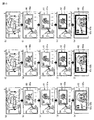
たとえば、特許文献1では、ステップアップ予告演出として、1枚目のウインドウ画面を表示している状態のもとで、発展(進展)可能な全てのウインドウ画面を表示させ、遊技者に大当りの期待感を示唆するようにしたものが開示されている(段落番号0009、図5)。
For example, in
しかし、前述したような従来のステップアップ予告演出では、1枚目のウインドウ画面が表示された時点でステップアップ予告の発展先がある程度判明してしまい、遊技者の期待感を十分に高めることができないという問題があった。 However, in the conventional step-up notice effect as described above, the development destination of the step-up notice becomes clear to some extent when the first window screen is displayed, and the player's expectation can be sufficiently enhanced. There was a problem that I could not.
本発明は、かかる実情に鑑み考え出されたものであり、その目的は、ステップアップ予告演出に関し、遊技の興趣を向上させることができる遊技機を提供することである。 The present invention has been conceived in view of such circumstances, and an object of the present invention is to provide a gaming machine that can improve the interest of the game with respect to a step-up notice effect.
(1) 所定条件の成立に基づいて遊技者にとって有利な有利状態に制御する遊技機(パチンコ遊技機1)であって、
前記有利状態に制御するか否かを決定する事前決定手段(遊技制御用マイクロコンピュータ560、図9のS60)と、
前記有利状態に制御される可能性を予告する予告演出として1段階から複数段階の予告ステップよりなるステップアップ予告演出を実行する予告演出実行手段(演出制御用マイクロコンピュータ100、図19のS504〜S507)と、
前記ステップアップ予告演出において実行され得る予告態様を表示する予告態様事前表示手段(演出制御用マイクロコンピュータ100、図19のS504〜S507)とを備え、
前記予告演出実行手段は、
前記ステップアップ予告演出において、少なくとも前記予告態様事前表示手段により表示された予告態様により予告演出を実行する通常制御(演出制御用マイクロコンピュータ100、図12〜図14)と、前記予告態様事前表示手段により表示された予告態様と異なる予告態様により予告演出を実行する特定制御(演出制御用マイクロコンピュータ100、図12、図15)と、のいずれかにより前記ステップアップ予告演出を実行し、
前記予告態様事前表示手段により表示された予告態様の種類に応じて、前記特定制御により前記ステップアップ予告演出を実行する確率を異ならせる(演出制御用マイクロコンピュータ100、図17、図18)。
(1) A gaming machine (pachinko gaming machine 1) that controls to an advantageous state advantageous to a player based on establishment of a predetermined condition ,
The a priori decision means to decide whether to control the advantageous state (game control microcomputer 560, S60 in FIG. 9),
Preliminary effect execution means (
Notice embodiment predisplay unit (
The notice effect execution means includes:
In the step-up notice effect, the normal control (the
Depending on the type of notice mode displayed by the notice mode pre-display means, the probability of executing the step-up notice effect is varied by the specific control (
このような構成によれば、予告態様事前表示手段により表示された予告態様の種類に応じて、特定制御によりステップアップ予告演出を実行する確率を異ならせるので、遊技者に対して、ステップアップ予告演出において実行され得る予告態様に興味を持たせることができるとともに、予告態様と異なる予告態様でステップアップ予告演出が実行される場合もあるのでステップアップ予告演出自体にも興味を持たせることができ、遊技の興趣が向上する。 According to such a configuration, since the probability of executing the step-up notice effect by the specific control is changed according to the type of the notice form displayed by the notice form prior display means , the step-up notice is given to the player. You can be interested in the notice mode that can be executed in the performance, and in some cases, the step-up notice effect may be executed in a different notice mode from the notice mode, so you can also be interested in the step-up notice effect itself. , The fun of gaming is improved.
(2) 前記(1)の遊技機において、
前記予告態様事前表示手段は、次段階以降の予告ステップにおいて実行され得る予告態様を複数方向に表示する。
(3) 前記(1)または(2)の遊技機において、
前記特定制御は、所定段階の予告ステップまで前記通常制御と同じ予告演出を実行し、次段階の予告ステップから前記通常制御と異なる予告演出を実行する制御を含む。
(4) 前記(1)〜(3)のいずれかの遊技機において、
前記予告態様の種類には、第1の予告態様(たとえば、「白−白−白」)と、当該第1の予告態様よりも前記有利状態に制御される期待度が高い第2の予告態様(たとえば、「白−白−黒」)とがあり、
前記予告演出実行手段は、
前記予告態様事前表示手段により前記第1の予告態様(たとえば、「白−白−白」)が表示されたときには前記第2の予告態様(たとえば、「白−白−黒」)が表示されたときよりも高確率で前記第1の予告態様より前記有利状態への制御の期待度が高い予告態様で前記ステップアップ予告演出をする(図17に示すように、最初に「白−白−白」が表示された方が最初に「白−白−黒」が表示される場合よりも高い確率で「白−白−黒」とステップアップする)。
(2) In the gaming machine of (1),
The prior notice mode pre-display means displays the notice form that can be executed in the next and subsequent notice steps in a plurality of directions.
(3) In the gaming machine (1) or (2),
The specific control includes a control that executes the same notice effect as the normal control until the notice step at a predetermined stage, and executes a notice effect different from the normal control from the notice step at the next stage.
(4) In the gaming machine of any one of (1) to (3),
The types of the notice modes include a first notice mode (for example, “white-white-white”) and a second notice mode having a higher degree of expectation controlled to the advantageous state than the first notice mode. (For example, “white-white-black”),
The notice effect execution means includes:
When the first notice mode (for example, “white-white-white”) is displayed by the notice mode prior display means, the second notice mode (for example, “white-white-black”) is displayed. The step-up notice effect is performed in a notice mode that has a higher probability of control than the first notice form and has a higher degree of expectation of control to the advantageous state than the first notice form (as shown in FIG. ”Is displayed,“ white-white-black ”is stepped up with a higher probability than when“ white-white-black ”is displayed first).
このような構成によれば、第1の予告態様が表示されたときには第2の予告態様が表示されたときよりも高確率で第1の予告態様より有利状態への制御の期待度が高い予告態様でステップアップ予告演出をするので、低期待度である第1の予告態様が表示されたときにも、ステップアップ予告演出に期待を持つことができる。 According to such a configuration, when the first notice mode is displayed, the notice with a higher probability of control to the advantageous state than the first notice mode is more likely than when the second notice mode is displayed. Since the step-up notice effect is performed in the form, the step-up notice effect can be expected even when the first notice form having the low expectation is displayed.
(5) 前記(1)〜(4)のいずれかの遊技機において、
前記予告演出実行手段は、前記特定制御により前記ステップアップ予告演出を実行したとき(変形例の(10)に示すように、予告態様として最初に「白−白−白」と表示され、ステップアップ予告演出における各予告ステップで「黒」色の枠のウインドウが表示されるような特定制御によりステップアップ予告演出を実行したとき)には、前記通常制御により前記ステップアップ予告演出を実行したとき(変形例の(10)に示すように、予告態様として最初に「白−白−白」と表示され、ステップアップ予告演出における各予告ステップで「白」色の枠のウインドウが表示されるような通常制御によりステップアップ予告演出を実行したとき)よりも、多段階の前記ステップアップ予告演出を実行する(変形例の(10)に示すように、予告態様として最初に「白−白−白」と表示され、SU1で「白」、SU2で「白」、SU3で「白」と制御する通常制御の場合は、3段階でステップアップ予告演出を終了し、最初に「白−白−白」と表示され、SU1で「白」、SU2で「白」、SU3で「黒」と制御する特定制御の場合は、さらにSU4で「黒」と表示される)。
(5) In any one of the gaming machines (1) to (4),
When the step-up notice effect is executed by the specific control (as shown in (10) of the modified example), the notice effect execution means is initially displayed as “white-white-white” as the notice mode, When the step-up notice effect is executed by the specific control such that the window of the “black” color frame is displayed in each notice step in the notice effect, the step-up notice effect is executed by the normal control ( As shown in (10) of the modified example, “white-white-white” is initially displayed as the notice mode, and a window of “white” color is displayed at each notice step in the step-up notice effect. The step-up notice effect is executed in multiple stages than when the step-up notice effect is executed by the normal control (as shown in (10) of the modification, In the case of normal control in which “white-white-white” is initially displayed as the notification mode and “white” is controlled by SU1, “white” by SU2, and “white” by SU3, a step-up notice effect is provided in three stages. In the case of specific control in which “white-white-white” is first displayed, and “white” is controlled by SU1, “white” by SU2, and “black” by SU3, “black” is further displayed by SU4. )
このような構成によれば、特定制御によりステップアップ予告演出を実行したときには、通常制御によりステップアップ予告演出を実行したときよりも、多段階のステップアップ予告演出を実行するので、遊技の興趣が向上する。 According to such a configuration, when the step-up notice effect is executed by the specific control, the multi-step step-up notice effect is executed rather than when the step-up notice effect is executed by the normal control. improves.
(6) 前記(1)〜(5)のいずれかの遊技機において、
前記予告態様事前表示手段により表示された予告態様(変形例の(11)に示すように、最初に表示される予告態様として「白−白−白」が表示される)とは異なる予告態様(変形例の(11)に示すように、各予告ステップにおいて通常とは異なる「黒」色の枠の予告態様)で前記ステップアップ予告演出が実行される場合に、特定の演出(変形例の(11)に示すように、たとえば、異なる予告態様が実行される前にキャラクタ64の色やキャラクタ64の持つ袋65の色を変化させる、異なる予告態様が実行される前にウインドウを袋65から出す際の空気の色を変える、異なる予告態様が実行されるときにウインドウ枠を点滅させて「白」、「黒」を繰り返し枠の色がどちらになるか分からなくするなどの演出を実行する)を実行する特定演出実行手段(演出制御用マイクロコンピュータ100)をさらに備える。
(6) In the gaming machine of any one of (1) to (5),
A notice mode different from the notice form displayed by the notice form prior display means (as shown in the modified example (11), “white-white-white” is displayed as the notice form displayed first) ( As shown in (11) of the modified example, when the step-up notice effect is executed in the notice mode of “black” frame different from the normal in each notice step), a specific effect (( 11), for example, the color of the
このような構成によれば、予告態様事前表示手段により表示された予告態様とは異なる予告態様でステップアップ予告演出が実行される場合に、特定の演出が実行されるので、異なる予告態様に発展すること(発展したこと)を遊技者が理解しやすい。 According to such a configuration, when the step-up notice effect is executed in a different notice form from the notice form displayed by the notice form prior display means, the specific effect is executed, so that it develops into a different notice mode. It is easy for the player to understand what has been developed.
(7) 前記(1)〜(6)のいずれかの遊技機において、
前記予告態様事前表示手段は、前記ステップアップ予告演出において実行され得る予告態様の候補として複数の候補を表示した後(変形例の(12)に示すように、袋を複数出す)、いずれかの候補を特定する演出(変形例の(12)に示すように、複数の袋の中のいずれの袋を選ぶかという演出)が可能である。
(7) In any one of the gaming machines (1) to (6),
The prior notice mode pre-display means displays a plurality of candidates as candidates for the notice form that can be executed in the step-up notice effect (multiple bags as shown in (12) of the modification), An effect of specifying a candidate (an effect of selecting which bag among a plurality of bags as shown in (12) of the modification) is possible.
このような構成によれば、ステップアップ予告演出において実行され得る予告態様の候補として複数の候補を表示した後、いずれかの候補を特定する演出が可能であるので、いずれの候補が特定されるかについて遊技者に注目させることができる。 According to such a configuration, after displaying a plurality of candidates as candidates notice aspects that may be Oite executed to step up with the subject Starring unloading, since it is possible effect of identifying any of the candidate, which of the candidates The player can be focused on whether it is specified.
(8) 前記(1)〜(7)のいずれかの遊技機において、
前記予告演出実行手段は、表示している予告態様の次にステップアップする可能性のある次予告態様を示す演出表示を第一方向側に表示する(変形例の(13)に示すように、ルーレットによりステップアップを示すような演出が実行される場合に、右回りに回るときには、2段階目のステップアップの予告態様を表示させる)とともに、当該次予告態様の次以降にステップアップする可能性のある予告態様を示す演出表示を前記第一方向とは異なる第二方向に表示する(変形例の(13)に示すように、左回りに回るときには3段階目のステップアップの予告態様を表示する)。
(8) In the gaming machine of any one of (1) to (7),
The notice effect execution means displays an effect display indicating the next notice mode that may be stepped up next to the displayed notice form on the first direction side (as shown in (13) of the modification, When an effect that indicates step-up is performed by roulette, when turning clockwise, the second-step step-up notice mode is displayed), and the possibility of step-up after the next notice mode is possible An effect display indicating a certain notice mode is displayed in a second direction different from the first direction (as shown in (13) of the modification, a notice form of the third step up is displayed when turning counterclockwise. To do).
このような構成によれば、表示している予告態様の次にステップアップする可能性のある次予告態様を示す演出表示を第一方向側に表示するとともに、当該次予告態様の次以降にステップアップする可能性のある予告態様を示す演出表示を第一方向とは異なる第二方向に表示されるので、遊技者は次以降にステップアップすることを認識することができ、遊技の興趣が向上する。 According to such a configuration, an effect display indicating the next notice mode that may be stepped up next to the displayed notice form is displayed on the first direction side, and a step is performed after the next notice form. The effect display showing the notice mode that may be improved is displayed in the second direction different from the first direction, so that the player can recognize that he will step up from the next, and the interest of the game is improved To do.
(9) 前記(1)〜(8)のいずれかの遊技機において、
前記事前決定手段によって前記特定表示結果とすると決定されたか否かを画像表示により予告するための複数の予告演出のうち、識別情報の変動表示中に実行する予告演出を決定する予告演出決定手段(演出制御用マイクロコンピュータ100)と、
前記予告演出決定手段によって実行すると決定された所定の予告演出の表示態様を、通常表示態様とするか、または前記通常表示態様よりも前記特定表示結果が導出表示される可能性が高いことを示すとともに予告表示の一部または全部に各予告演出で共通のモチーフ態様(たとえば、桜柄)を出現させる特殊表示態様とするかを決定する予告態様決定手段(演出制御用マイクロコンピュータ100)と、
前記事前決定手段によって前記特定表示結果としないことに決定されている識別情報の変動表示中において、出現させる前記モチーフ態様の数を所定数未満(たとえば、3未満)に制限するモチーフ態様制限手段(演出制御用マイクロコンピュータ100)とを備え、
前記予告演出実行手段は、前記予告態様決定手段が決定した表示態様で、識別情報の変動表示中に前記予告演出決定手段によって実行すると決定された各予告演出をそれぞれ実行可能であり、
前記モチーフ態様制限手段は、所定の予告演出に対してあらかじめ定められた優先順位に従って出現させる前記モチーフ態様の数を前記所定数未満に制限し、前記優先順位は、実行割合が高い予告演出ほど制限対象となりやすいように定められている(変形例の(14)に示すように、演出制御用マイクロコンピュータ100は、実行割合が高い専用演出用のステップアップ予告演出で出現する桜柄を制限し、次に予め定められた書き替えテーブルに従って、共通演出用の予告演出の中で実行割合が高いものから順に桜柄を制限する)。
(9) In any of the gaming machines (1) to (8),
A notice effect determining means for determining a notice effect to be executed during a variable display of identification information among a plurality of notice effects for notifying by image display whether or not the specific display result has been decided by the prior decision means. (Production control microcomputer 100);
The display form of the predetermined notice effect determined to be executed by the notice effect determining means is set as the normal display form, or indicates that the specific display result is more likely to be derived and displayed than the normal display form. And a notice mode determining means (a
Motif mode limiting means for limiting the number of the motif modes to appear during the variable display of the identification information determined not to be the specific display result by the predetermining means to be less than a predetermined number (for example, less than 3). (Production control microcomputer 100),
The notice effect executing means is capable of executing each notice effect determined to be executed by the notice effect determining means during the display of the identification information in the display mode determined by the notice aspect determining means,
The motif mode restricting means limits the number of motif modes to appear according to a predetermined priority order for a predetermined notice effect, and the priority order is restricted for a notice effect with a higher execution ratio. (As shown in (14) of the modified example, the
このような構成によれば、予告演出においてモチーフ態様を出現させる演出を行う場合に、実行割合が低い予告演出でモチーフ態様が出現しなくなってしまう事態を抑制することができる。 According to such a structure, when performing the effect which makes a motif aspect appear in a notice effect, the situation where a motif aspect stops appearing in a notice effect with a low execution rate can be suppressed.
以下、本発明の実施の形態を、図面を参照して説明する。なお、遊技機の一例としてパチンコ遊技機を示すが、本発明はパチンコ遊技機に限られず、所定条件の成立に基づいて遊技者にとって有利な有利状態(特定遊技状態)に制御する遊技機であれば、どのような遊技機であってもよい。 Hereinafter, embodiments of the present invention will be described with reference to the drawings. Although a pachinko gaming machine is shown as an example of the gaming machine, the present invention is not limited to a pachinko gaming machine, and may be a gaming machine that controls to an advantageous state ( specific gaming state ) advantageous to a player based on establishment of a predetermined condition. Any game machine may be used.
[第1実施形態]
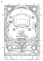
以下、本発明の実施の形態を、図面を参照して説明する。まず、遊技機の一例であるパチンコ遊技機1の全体の構成について説明する。図1はパチンコ遊技機1を正面からみた正面図である。図2は当り種別表である。
[First Embodiment]
Hereinafter, embodiments of the present invention will be described with reference to the drawings. First, the overall configuration of a
パチンコ遊技機1は、縦長の方形状に形成された外枠(図示せず)と、外枠の内側に開閉可能に取付けられた遊技枠とで構成される。また、パチンコ遊技機1は、遊技枠に開閉可能に設けられている額縁状に形成されたガラス扉枠2を有する。遊技枠は、外枠に対して開閉自在に設置される前面枠(図示せず)と、機構部品等が取付けられる機構板(図示せず)と、それらに取付けられる種々の部品(後述する遊技盤6を除く)とを含む構造体である。
The
ガラス扉枠2の下部表面には打球供給皿(上皿)3がある。打球供給皿3の下部には、打球供給皿3に収容しきれない遊技球を貯留する余剰球受皿4、および、打球を発射する打球操作ハンドル(操作ノブ)5等が設けられている。また、ガラス扉枠2の背面には、遊技盤6が着脱可能に取付けられている。遊技盤6は、それを構成する板状体と、その板状体に取付けられた種々の部品とを含む構造体である。また、遊技盤6の前面には、打込まれた遊技球が流下可能な遊技領域7が形成されている。
On the lower surface of the
余剰球受皿(下皿)4を形成する部材には、たとえば下皿本体の上面における手前側の所定位置(たとえば下皿の中央部分)等に、スティック形状(棒形状)に構成され、遊技者が把持して複数方向(前後左右)に傾倒する操作が可能なスティックコントローラ122が取付けられている。なお、スティックコントローラ122には、遊技者がスティックコントローラ122の操作桿を操作手(たとえば左手等)で把持した状態において、所定の操作指(たとえば人差し指等)で押引操作すること等により所定の指示操作が可能なトリガボタン125(図3参照)が設けられ、スティックコントローラ122の操作桿の内部には、トリガボタン125に対する押引操作等による所定の指示操作を検知するトリガセンサ121(図3参照)が内蔵されている。また、スティックコントローラ122の下部における下皿の本体内部等には、操作桿に対する傾倒操作を検知する傾倒方向センサユニット123(図3参照)が設けられている。また、スティックコントローラ122には、スティックコントローラ122を振動動作させるためのバイブレータ用モータ126(図3参照)が内蔵されている。
The member that forms the extra ball tray (lower tray) 4 is configured in a stick shape (bar shape), for example, at a predetermined position on the front side of the upper surface of the lower tray body (for example, the central portion of the lower tray). A
打球供給皿(上皿)3を形成する部材には、たとえば上皿本体の上面における手前側の所定位置(たとえばスティックコントローラ122の上方)等に、遊技者が押下操作等により所定の指示操作を可能なプッシュボタン120が設けられている。プッシュボタン120は、遊技者からの押下操作等による所定の指示操作を、機械的、電気的、あるいは、電磁的に、検出できるように構成されていればよい。プッシュボタン120の設置位置における上皿の本体内部等には、プッシュボタン120に対してなされた遊技者の操作行為を検知するプッシュセンサ124(図3参照)が設けられていればよい。図1に示す構成例では、プッシュボタン120とスティックコントローラ122の取付位置が、上皿及び下皿の中央部分において上下の位置関係にある。これに対して、上下の位置関係を保ったまま、プッシュボタン120及びスティックコントローラ122の取付位置を、上皿及び下皿において左右のいずれかに寄せた位置としてもよい。あるいは、プッシュボタン120とスティックコントローラ122との取付位置が上下の位置関係にはなく、たとえば左右の位置関係にあるものとしてもよい。
A member that forms the hitting ball supply tray (upper plate) 3 is operated by a player to perform a predetermined instruction operation by a pressing operation or the like at a predetermined position on the upper surface of the upper plate body (for example, above the stick controller 122). A
なお、本実施の形態では、遊技者が操作可能な操作手段の一例として、プッシュボタン120と、トリガボタン125を有するスティックコントローラ122とを設けた例を示した。しかし、これに限らず、操作手段としては、プッシュボタン120とスティックコントローラ122とのいずれか1つのみを設けてもよい。また、操作手段としては、レバースイッチ、および、ジョグダイヤル等のその他の操作手段を設けてもよい。
In the present embodiment, an example in which the
遊技領域7の中央付近には、各々を識別可能な複数種類の識別情報としての演出図柄を変動表示(可変表示ともいう)可能な演出表示装置9が設けられている。遊技領域7における演出表示装置9の右側方には、各々を識別可能な複数種類の識別情報としての第1特別図柄を変動表示する第1特別図柄表示器8aと、各々を識別可能な複数種類の識別情報としての第2特別図柄を変動表示する第2特別図柄表示器8bとが設けられている。
In the vicinity of the center of the
第1特別図柄表示器8aおよび第2特別図柄表示器8bのそれぞれは、数字および文字を変動表示可能な簡易で小型の表示器(たとえば7セグメントLED)で構成されている。演出表示装置9は、液晶表示装置(LCD)で構成されており、表示画面において、第1特別図柄または第2特別図柄の変動表示に同期した演出図柄の変動表示等の各種画像を表示する表示領域が設けられる。このような表示領域には、たとえば「左」,「中」,「右」の3つの装飾用(演出用)の演出図柄を変動表示する図柄表示領域が形成される。
Each of the first special
第1特別図柄表示器8aおよび第2特別図柄表示器8bのそれぞれは、主基板(遊技制御基板)に搭載されている遊技制御用マイクロコンピュータによって制御される。演出表示装置9は、演出制御基板に搭載されている演出制御用マイクロコンピュータによって制御される。第1特別図柄表示器8aで第1特別図柄の変動表示が実行されているときに、その変動表示に伴なって演出表示装置9で演出表示が実行され、第2特別図柄表示器8bで第2特別図柄の変動表示が実行されているときに、その変動表示に伴なって演出表示装置9で演出表示が実行されるので、遊技の進行状況を把握しやすくすることができる。
Each of the first
第1特別図柄表示器8aに特定表示結果としての大当り表示結果(大当り図柄)が導出表示されたとき、または、第2特別図柄表示器8bに特定表示結果としての大当り表示結果(大当り図柄)が導出表示されたときには、演出表示装置9においても、特定表示結果としての大当り表示結果(大当り図柄の組合せ)が導出表示される。このように変動表示の表示結果として特定表示結果が表示されたときには、遊技者にとって有利な価値(有利価値)が付与される有利状態としての特定遊技状態(大当り遊技状態)に制御される。
When the jackpot display result (bonus symbol) as the specific display result is derived and displayed on the first
また、演出表示装置9において、最終停止図柄(たとえば左右中図柄のうち中図柄)となる図柄以外の図柄が、所定時間継続して、大当り図柄(たとえば左中右の図柄が同じ図柄で揃った図柄の組合せ)と一致している状態で停止、揺動、拡大縮小もしくは変形している状態、または、複数の図柄が同一図柄で同期して変動したり、表示図柄の位置が入れ替わっていたりして、最終結果が表示される前で大当り発生の可能性が継続している状態(以下、これら状態をリーチ状態という。)で行なわれる演出をリーチ演出という。
Further, in the
ここで、リーチ状態は、演出表示装置9の表示領域において停止表示された演出図柄が大当り組合せの一部を構成しているときに未だ停止表示されていない演出図柄の変動が継続している表示状態、または、全部もしくは一部の演出図柄が大当り組合せの全部または一部を構成しながら同期して変動している表示状態である。言い換えると、リーチとは、複数の変動表示領域において識別情報が特定表示結果を構成しているが少なくとも一部の変動領域が変動表示中である状態をいう。この実施形態において、リーチ状態は、たとえば、左,右の図柄表示領域で同じ図柄が停止し、中の図柄表示領域で図柄が停止していない状態で形成される。リーチ状態が形成されるときの左,右の図柄表示領域で停止された図柄は、リーチ形成図柄、または、リーチ図柄と呼ばれる。
Here, in the reach state, when the effect symbols that are stopped and displayed in the display area of the
そして、リーチ状態における表示演出が、リーチ演出表示(リーチ演出)である。また、リーチの際に、通常と異なる演出がランプや音で行なわれることがある。この演出をリーチ演出という。また、リーチの際に、キャラクタ(人物等を模した演出表示であり、図柄(演出図柄等)とは異なるもの)を表示させたり、演出表示装置9の背景画像の表示態様(たとえば、色等)を変化させたりすることがある。このキャラクタの表示や背景の表示態様の変化をリーチ演出表示という。また、リーチの中には、それが出現すると、通常
のリーチ(ノーマルリーチ)に比べて、大当りが発生しやすいように設定されたものがある。このような特別のリーチをスーパーリーチという。また、リーチの中には、特別なスーパーリーチ以外のリーチとして、基本的なリーチであるノーマルリーチが含まれている。ノーマルリーチは、スーパーリーチよりも大当りが発生しにくいように設定されたものである。
The display effect in the reach state is reach effect display (reach effect). In addition, during the reach, an unusual performance may be performed with a lamp or sound. This production is called reach production. Further, in the case of reach, a character (an effect display imitating a person or the like, which is different from a design (effect design etc.)) or a display mode (for example, a color etc.) of the background image of the
演出表示装置9の右方には、各々を識別可能な識別情報としての第1特別図柄を変動表示する第1特別図柄表示器(第1変動表示部)8aが設けられている。第1特別図柄表示器8aは、0〜9の数字等の特別図柄を変動表示可能な簡易で小型の表示器(たとえば7セグメントLED)で実現されている。また、演出表示装置9の右方(第1特別図柄表示器8aの右隣)には、各々を識別可能な識別情報としての第2特別図柄を変動表示する第2特別図柄表示器(第2変動表示部)8bが設けられている。第2特別図柄表示器8bは、0〜9の数字等の特別図柄を変動表示可能な簡易で小型の表示器(たとえば7セグメントLED)で実現されている。
On the right side of the
以下、第1特別図柄と第2特別図柄とを特別図柄と総称することがあり、第1特別図柄表示器8aと第2特別図柄表示器8bとを特別図柄表示器(変動表示部)と総称することがある。
Hereinafter, the first special symbol and the second special symbol may be collectively referred to as a special symbol, and the first
なお、この実施の形態では、2つの特別図柄表示器8a,8bを備える場合を示しているが、遊技機は、特別図柄表示器を1つのみ備えるものであってもよい。
Although this embodiment shows a case where two
第1特別図柄または第2特別図柄の変動表示は、変動表示の実行条件である第1始動条件(第1実行条件)または第2始動条件(第2実行条件)が成立(たとえば、遊技球が第1始動入賞口13または第2始動入賞口14を通過(入賞を含む)したこと)した後、変動表示の開始条件(たとえば、保留記憶数が0でない場合であって、第1特別図柄および第2特別図柄の変動表示が実行されていない状態であり、かつ、大当り遊技が実行されていない状態)が成立したことに基づいて開始され、変動表示時間(変動時間)が経過すると表示結果(停止図柄)を導出表示する。本実施の形態では、特別図柄の変動表示に関し、第1特別図柄による第1実行条件と、第2特別図柄による第2実行条件との両方が成立しているときには、第2特別図柄の変動表示の開始条件が、第1特別図柄の変動表示の開始条件よりも優先的に成立し、第2特別図柄の変動表示が優先的に実行される。なお、遊技球が通過するとは、入賞口やゲート等の予め入賞領域として定められている領域を遊技球が通過したことであり、入賞口に遊技球が入った(入賞した)ことを含む概念である。また、表示結果を導出表示するとは、図柄(識別情報の例)を最終的に停止表示させることである。
In the variation display of the first special symbol or the second special symbol, the first start condition (first execution condition) or the second start condition (second execution condition) which is the execution condition of the variation display is established (for example, the game ball is After passing through the first
演出表示装置9の下方には、第1始動入賞口13を有する入賞装置が設けられている。第1始動入賞口13に入賞した遊技球は、遊技盤6の背面に導かれ、第1始動口スイッチ13aによって検出される。
A winning device having a first
また、第1始動入賞口(第1始動口)13を有する入賞装置の下方には、遊技球が入賞可能な第2始動入賞口14を有する可変入賞球装置15が設けられている。第2始動入賞口(第2始動口)14に入賞した遊技球は、遊技盤6の背面に導かれ、第2始動口スイッチ14aによって検出される。可変入賞球装置15は、ソレノイド16によって開状態とされる。可変入賞球装置15が開状態になることによって、遊技球が第2始動入賞口14に入賞可能になり(始動入賞し易くなり)、遊技者にとって有利な状態になる。可変入賞球装置15が開状態になっている状態では、第1始動入賞口13よりも、第2始動入賞口14に遊技球が入賞しやすい。また、可変入賞球装置15が閉状態になっている状態では、遊技球は第2始動入賞口14に入賞しない。したがって、可変入賞球装置15が閉状態になっている状態では、第2始動入賞口14よりも、第1始動入賞口13に遊技球が入賞しやすい。なお、可変入賞球装置15が閉状態になっている状態において、入賞はしづらいものの、入賞することは可能である(すなわち、遊技球が入賞しにくい)ように構成されていてもよい。以下、第1始動入賞口13と第2始動入賞口14とを総称して始動入賞口または始動口ということがある。
A variable winning
第2特別図柄表示器8bの上方には、第2始動入賞口14に入った有効入賞球数すなわち第2保留記憶数を表示する4つの表示器からなる第2特別図柄保留記憶表示器18bが設けられている。第2特別図柄保留記憶表示器18bは、有効始動入賞がある毎に、点灯する表示器の数を1増やす。そして、第2特別図柄表示器8bでの変動表示が開始される毎に、点灯する表示器の数を1減らす。
Above the second
また、第2特別図柄保留記憶表示器18bのさらに上方には、第1始動入賞口13に入った有効入賞球数すなわち第1保留記憶数(保留記憶を、始動記憶または始動入賞記憶ともいう。)を表示する4つの表示器からなる第1特別図柄保留記憶表示器18aが設けられている。第1特別図柄保留記憶表示器18aは、有効始動入賞がある毎に、点灯する表示器の数を1増やす。そして、第1特別図柄表示器8aでの変動表示が開始される毎に、点灯する表示器の数を1減らす。
Further, above the second special symbol
遊技機には、遊技者が打球操作ハンドル5を操作することに応じて駆動モータを駆動し、駆動モータの回転力を利用して遊技球を遊技領域7に発射する打球発射装置(図示せず)が設けられている。打球発射装置から発射された遊技球は、遊技領域7を囲むように円形状に形成された打球レールを通って遊技領域7に入り、その後、遊技領域7を下りてくる。遊技球が第1始動入賞口13に入り第1始動口スイッチ13aで検出されると、第1特別図柄の変動表示を開始できる状態であれば(たとえば、特別図柄の変動表示が終了し、第1特別図柄の変動表示が開始可能となる第1の開始条件が成立したこと)、第1特別図柄表示器8aにおいて第1特別図柄の変動表示(変動)が開始されるとともに、演出表示装置9において演出図柄の変動表示が開始される。すなわち、第1特別図柄および演出図柄の変動表示は、第1始動入賞口13への入賞に対応する。第1特別図柄の変動表示を開始できる状態でなければ、第1保留記憶数が上限値に達していないことを条件として、第1保留記憶数を1増やす。
In the gaming machine, a ball striking device (not shown) that drives a driving motor in response to a player operating the batting operation handle 5 and uses the rotational force of the driving motor to launch a gaming ball to the gaming area 7. ) Is provided. A game ball launched from the ball striking device enters the
遊技球が第2始動入賞口14に入り第2始動口スイッチ14aで検出されると、第2特別図柄の変動表示を開始できる状態であれば(たとえば、特別図柄の変動表示が終了し、第2特別図柄の変動表示が開始可能となる第2の開始条件が成立したこと)、第2特別図柄表示器8bにおいて第2特別図柄の変動表示(変動)が開始されるとともに、演出表示装置9において演出図柄の変動表示が開始される。すなわち、第2特別図柄および演出図柄の変動表示は、第2始動入賞口14への入賞に対応する。第2特別図柄の変動表示を開始できる状態でなければ、第2保留記憶数が上限値に達していないことを条件として、第2保留記憶数を1増やす。
When the game ball enters the second
演出表示装置9は、第1特別図柄表示器8aによる第1特別図柄の変動表示時間中、および第2特別図柄表示器8bによる第2特別図柄の変動表示時間中に、装飾用(演出用)の図柄としての演出図柄の変動表示を行なう。第1特別図柄表示器8aにおける第1特別図柄の変動表示と、演出表示装置9における演出図柄の変動表示とは同期している。また、第2特別図柄表示器8bにおける第2特別図柄の変動表示と、演出表示装置9における演出図柄の変動表示とは同期している。また、第1特別図柄表示器8aにおいて大当り図柄が停止表示されるときと、第2特別図柄表示器8bにおいて大当り図柄が停止表示されるときには、演出表示装置9において大当り表示結果として大当りを想起させるような演出図柄の組合せが停止表示される。
The
また、演出表示装置9の表示画面の下部には、第1保留記憶数を表示する第1保留記憶表示部18cと、第2保留記憶数を表示する第2保留記憶表示部18dとが形成される。なお、第1保留記憶数と第2保留記憶数との合計である合計数(合算保留記憶数)を表示する領域(合算保留記憶表示部)が設けられるようにしてもよい。そのように、合計数を表示する合算保留記憶表示部が設けられているようにすれば、変動表示の開始条件が成立していない実行条件の成立数の合計を把握しやすくすることができる。
Further, a first reserved
また、図1に示すように、可変入賞球装置15の下方には、特別可変入賞球装置20が設けられている。特別可変入賞球装置20は開閉板を備え、第1特別図柄表示器8aに特定表示結果(大当り図柄)が導出表示されたときと、第2特別図柄表示器8bに特定表示結果(大当り図柄)が導出表示されたときに生起する特定遊技状態(大当り遊技状態)においてソレノイド21によって開閉板が開放状態に制御されることによって、入賞領域となる大入賞口が開放状態になる。大入賞口に入賞した遊技球はカウントスイッチ23で検出される。
Further, as shown in FIG. 1, a special variable winning
大当り遊技状態においては、特別可変入賞球装置20が開放状態と閉鎖状態とを繰返す繰返し継続制御が行なわれる。繰返し継続制御において、特別可変入賞球装置20が開放されている状態が、ラウンドと呼ばれる(以下、単にRともいう)。これにより、繰返し継続制御は、ラウンド制御とも呼ばれる。本実施の形態では、大当りの種別が複数設けられており、大当りとすることが決定されたときには、いずれかの大当り種別が選択される。
In the big hit gaming state, repeated continuous control is performed in which the special variable winning
演出表示装置9の左方には、各々を識別可能な普通図柄を変動表示する普通図柄表示器10が設けられている。この実施の形態では、普通図柄表示器10は、0〜9の数字を変動表示可能な簡易で小型の表示器(たとえば7セグメントLED)で実現されている。すなわち、普通図柄表示器10は、0〜9の数字(または、記号)を変動表示するように構成されている。また、小型の表示器は、たとえば方形状に形成されている。
On the left side of the
遊技球がゲート32を通過しゲートスイッチ32aで検出されると、普通図柄表示器10の表示の変動表示が開始される。そして、普通図柄表示器10における停止図柄が所定の図柄(当り図柄。たとえば、図柄「7」。)である場合に、可変入賞球装置15が所定回数、所定時間だけ遊技者にとって不利な閉状態から遊技者にとって有利な開状態に変化する。普通図柄表示器10の近傍には、ゲート32を通過した入賞球数を表示する4つのLEDによる表示部を有する普通図柄保留記憶表示器41が設けられている。ゲート32への遊技球の通過がある毎に、すなわちゲートスイッチ32aによって遊技球が検出される毎に、普通図柄保留記憶表示器41は点灯するLEDを1増やす。そして、普通図柄表示器10の変動表示が開始される毎に、点灯するLEDを1減らす。
When the game ball passes through the
遊技盤6の下部には、入賞しなかった打球が取込まれるアウト口26がある。また、遊技領域7の外側の左右上部および左右下部には、所定の音声出力として効果音や音声を発声する4つのスピーカ27が設けられている。遊技領域7の外周には、前面枠に設けられた枠LED28が設けられている。
At the lower part of the
また、プリペイドカードが挿入されることによって球貸しを可能にするプリペイドカードユニット(以下、単に「カードユニット」ともいう。)が、パチンコ遊技機1に隣接して設置される(図示せず)。 In addition, a prepaid card unit (hereinafter also simply referred to as “card unit”) that enables lending a ball by inserting a prepaid card is installed adjacent to the pachinko gaming machine 1 (not shown).
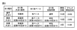
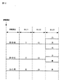
図2の当り種別表においては、大当りにおける当りの種別ごとに、大当り遊技状態の終了後の大当り確率、大当り遊技状態の終了後のベース、大当り遊技状態終了後の変動時間、大当りにおける開放回数(ラウンド数)、および、各ラウンドの開放時間が示されている。図2に示すように、この実施の形態では、ラウンド数が異なる大当り遊技状態として、15ラウンドの大当り遊技状態と2ラウンドの大当り遊技状態との複数種類の大当り遊技状態が設けられている。 In the hit type table of FIG. 2, for each hit type in the big hit, the big hit probability after the end of the big hit gaming state, the base after the end of the big hit gaming state, the variation time after the end of the big hit gaming state, the number of releases in the big hit ( The number of rounds) and the opening time of each round are shown. As shown in FIG. 2, in this embodiment, as the jackpot gaming state with different numbers of rounds, a plurality of types of jackpot gaming states of 15 rounds of jackpot gaming state and two rounds of jackpot gaming state are provided.
具体的に、15ラウンドの大当り遊技状態においては、特別可変入賞球装置20が、開放状態とされた後、所定の開放状態の終了条件(開放状態において所定期間(たとえば29秒間)が経過したこと、または、所定個数(たとえば10個)の入賞球が発生したという開放終了条件)が成立したことに応じて閉鎖状態とされる。そして、開放終了条件が成立すると、継続権が発生し、特別可変入賞球装置20の開放が再度行なわれる。継続権の発生は、大当り遊技状態における開放回数が予め定められた上限値となる15ラウンド(最終ラウンド)に達するまで繰返される。
Specifically, in the 15-round big hit game state, after the special variable winning
また、2ラウンドの大当り遊技状態においては、特別可変入賞球装置20が、開放状態とされた後、所定の開放状態の終了条件(開放状態において所定期間(たとえば0.5秒間)が経過したこと、または、所定個数(たとえば10個)の入賞球が発生したという開放終了条件)が成立したことに応じて閉鎖状態とされる。そして、開放終了条件が成立すると、継続権が発生し、特別可変入賞球装置20の開放が再度行なわれる。継続権の発生は、大当り遊技状態における開放回数が予め定められた上限値となる2ラウンド(最終ラウンド)に達するまで繰返される。
Also, in the two-round big hit gaming state, after the special variable winning
このように、2ラウンドの大当りは、大入賞口の開放回数が15ラウンドよりも少ない回数(この実施の形態では2回)まで許容されるが、大入賞口の開放時間が短い(たとえば、0.5秒間)大当り種類(種別)である。また、本実施の形態の場合は、2ラウンドの大当りとして、大入賞口の開放時間が極めて短く(0.5秒間)、実質的に大入賞口に入賞することが不可能であり、実質的に賞球(入賞に対して払出される景品球)が得られない当りが設けられている。 In this way, the big win of 2 rounds is allowed up to the number of times of opening the big prize opening is less than 15 rounds (2 times in this embodiment), but the opening time of the big prize opening is short (for example, 0 .5 seconds) type of jackpot (type). In the case of the present embodiment, as a big hit of two rounds, the opening time of the grand prize opening is extremely short (0.5 seconds), and it is substantially impossible to win the big prize opening. In addition, there is a win where a prize ball (a prize ball paid out for winning) cannot be obtained.
なお、2ラウンドの大当りとしては、実質的に賞球が得られない当りのみを設けてもよく、賞球を得ることができる当りのみを設けてもよく、実質的に賞球が得られない当りと賞球を得ることができる当りとの両方を設けてもよい。 In addition, as a big hit of two rounds, it is possible to provide only a hit where a prize ball cannot be obtained, or only a hit where a prize ball can be obtained. Both a win and a win from which a prize ball can be obtained may be provided.
「大当り」のうち、15ラウンドまたは2ラウンドの大当り遊技状態に制御された後、特別遊技状態として、通常状態(確変状態でない通常の遊技状態)に比べて大当りとすることに決定される確率が高い状態である確変状態(確率変動状態の略語であり、高確率状態ともいう)に移行する大当りの種類(種別)は、「確変大当り」と呼ばれる。本実施の形態では、15ラウンドの確変大当りを「確変大当り」と呼び、2ラウンドの確変大当りを後述するような理由で「突確大当り」と呼ぶ。また、本実施の形態では、特別遊技状態としては、確変状態に付随して、特別図柄や演出図柄の変動時間(変動表示期間)が非時短状態よりも短縮される時短状態に制御される場合がある。なお、特別遊技状態としては、確変状態とは独立して時短状態に制御される場合があるようにしてもよい。 Among the “big hits”, after being controlled to the big hit game state of 15 rounds or 2 rounds, the probability that the special game state is determined to be a big hit compared to the normal state (the normal game state which is not the probability change state) A type of jackpot (type) that shifts to a high probability state (an abbreviation of a probability variation state, also referred to as a high probability state) is called “probability big hit”. In the present embodiment, the 15-round probability variation big hit is called “probability big hit”, and the 2-round probability variation big hit is called “surprising big hit” for the reason described later. In the present embodiment, the special gaming state is controlled to a time-short state in which the variation time (variation display period) of the special symbol or the production symbol is shortened from the non-time-short state in association with the probability variation state. There is. Note that the special gaming state may be controlled to the short time state independently of the probability variation state.
このように、時短状態に移行することによって、特別図柄や演出図柄の変動時間が短縮されるので、時短状態となったときには、有効な始動入賞が発生しやすくなり大当り遊技が行なわれる可能性が高まる。 In this way, the transition time to the short-time state reduces the variation time of the special symbol and the production symbol. Therefore, when the short-time state is reached, it is easy for an effective start winning to occur, and a big hit game may be performed. Rise.
なお、「大当り」のうち、15ラウンドの大当り遊技状態に制御された後、確変状態に移行しない大当りの種類(種別)は、「通常大当り」と呼ばれる。 Note that the type of jackpot (type) that does not shift to the probability change state after being controlled to the 15-round jackpot gaming state among the “hits” is called “ordinary jackpot”.
また、特別遊技状態としては、確変状態または時短状態に付随して、可変入賞球装置15が開状態になる頻度を高くすることにより可変入賞球装置15に遊技球が進入する頻度を高くして可変入賞球装置15への入賞を容易化(高進入化、高頻度化)する電チューサポート制御状態に制御される場合がある。電チューサポート制御状態は、後述するように高ベース状態であるので、以下の説明においては、主として高ベース状態と呼ぶ。
Further, as the special game state, the frequency of the game ball entering the variable
ここで、電チューサポート制御について説明する。電チューサポート制御としては、普通図柄の変動時間(変動表示開始時から表示結果の導出表示時までの時間)を短縮して早期に表示結果を導出表示させる制御(普通図柄短縮制御)、普通図柄の停止図柄が当り図柄になる確率を高める制御(普通図柄確変制御)、可変入賞球装置15の開放時間を長くする制御(開放時間延長制御)、および、可変入賞球装置15の開放回数を増加させる制御(開放回数増加制御)が行なわれる。このような制御が行なわれると、当該制御が行なわれていないときと比べて、可変入賞球装置15が開状態となっている時間比率が高くなるので、第2始動入賞口14への入賞頻度が高まり、遊技球が始動入賞しやすくなる(特別図柄表示器8a,8bや演出表示装置9における変動表示の実行条件が成立しやすくなる)。また、このような制御によって第2始動入賞口14への入賞頻度が高まることにより、第2始動条件の成立頻度および/または第2特別図柄の変動表示の実行頻度が高まる遊技状態となる。
Here, electric Chu support control will be described. As electric support control, normal symbol variation time (time from the start of variation display to display result derivation display time) is shortened and the display result is derived and displayed at an early stage (normal symbol shortening control), normal symbol The control to increase the probability that the stop symbol will be a winning symbol (ordinary symbol probability changing control), the control to increase the opening time of the variable winning ball device 15 (opening time extension control), and the number of opening of the variable winning
このような電チューサポート制御により第2始動入賞口14への入賞頻度が高められた状態(高頻度状態)は、発射球数に対して入賞に応じて賞球として払出される遊技球数の割合である「ベース」が、当該制御が行なわれないときと比べて、高い状態であるので、「高ベース状態」と呼ばれる。また、このような制御が行なわれないときは、「低ベース状態」と呼ばれる。また、このような制御は、可変入賞球装置15、すなわち、電動チューリップにより入賞をサポートすることにより可変入賞球装置15への入賞を容易化する制御であり、「電チューサポート制御」と呼ばれる。
The state in which the winning frequency to the second
この実施の形態においては、大当り確率の状態を示す用語として、「高確率状態(確変状態)」と、「低確率状態(非確変状態)」とを用い、ベースの状態の組合せを示す用語として、「高ベース状態(電チューサポート制御状態)」と、「低ベース状態(非電チューサポート制御状態)」とを用いる。 In this embodiment, “high probability state (probability variation state)” and “low probability state (non-probability variation state)” are used as terms indicating the state of jackpot probability, and terms indicating a combination of base states are used. , “High base state (electric Chu support control state)” and “low base state (non-electric Chu support control state)” are used.
また、この実施の形態においては、大当り確率の状態およびベースの状態の組合せを示す用語として、「低確低ベース状態」、および、「高確高ベース状態」を用いる。「低確低ベース状態」とは、大当り確率の状態が低確率状態で、かつ、ベースの状態が低ベース状態であることを示す状態である。「高確高ベース状態」とは、大当り確率の状態が高確率状態で、かつ、ベースの状態が高ベース状態であることを示す状態である。 Further, in this embodiment, “low accuracy low base state” and “high accuracy high base state” are used as terms indicating a combination of the big hit probability state and the base state. The “low probability low base state” is a state indicating that the state of the big hit probability is the low probability state and the base state is the low base state. The “high probability high base state” is a state indicating that the state of the big hit probability is the high probability state and the base state is the high base state.
この実施の形態においては、高確率状態に制御されたときに、時短状態および高ベース状態に制御されるが、時短状態および高ベース状態は、制御の開始条件および終了条件が同じであるので、時短状態および高ベースに制御されている状態を、時短状態という用語で代表して示す場合があり、高ベース状態という用語で代表して示す場合がある。 In this embodiment, when controlled to the high probability state, it is controlled to the short time state and the high base state, but the short time state and the high base state have the same control start condition and end condition, The state of being controlled to the short time state and the high base may be represented by the term of the short time state, and may be represented by the term of the high base state.
図2に示すように、15ラウンドの大当りとしては、通常大当りと確変大当りとの複数種類の大当りが設けられている。また、2ラウンドの大当りとしては、突然確変大当り(以下、突確大当りという略称で呼ぶ)が設けられている。 As shown in FIG. 2, as the big hit of 15 rounds, a plurality of types of big hits, a normal big hit and a probable big hit, are provided. In addition, as the big hit of the two rounds, a sudden probability variation big hit (hereinafter referred to as an abbreviated big hit) is provided.
通常大当りは、15ラウンドの大当り遊技状態の終了後に、非確変状態、非時短状態、および、低ベース状態(低確低ベース状態)に制御される大当りである。 The normal jackpot is a jackpot that is controlled to the non-probability changing state, the non-time-short state, and the low base state (low probability low base state) after the end of the 15 rounds of the big hit gaming state.
確変大当りは、15ラウンドの大当り遊技状態の終了後に、確変状態、時短状態、および、高ベース状態(高確高ベース状態)に移行する制御が行なわれる大当りである。確変大当りにおいては、このような高確高ベース状態が、変動表示が100回という所定回数実行されるまでという条件と、次回の大当りが発生するまでという条件とのいずれか早い方の条件が成立するまでの期間継続する。 The probability variation jackpot is a jackpot in which control is performed to shift to the probability variation state, the time-short state, and the high base state (high probability high base state) after the end of the 15 rounds of the jackpot gaming state. In the probabilistic big hit, such a high-precise base state is satisfied, whichever is earlier, a condition that the fluctuation display is executed a predetermined number of times of 100 times or a condition that the next big hit occurs. It continues for a period until.
突確大当りは、2ラウンドの大当り遊技状態の終了後に、確変状態、時短状態、および、高ベース状態(高確高ベース状態)に移行する制御が行なわれる大当りである。確変大当りにおいては、このような高確高ベース状態が、変動表示が100回という所定回数実行されるまでという条件と、次回の大当りが発生するまでという条件とのいずれか早い方の条件が成立するまでの期間継続する。 The sudden hit big hit is a big hit in which, after the end of two rounds of the big hit gaming state, control is performed to shift to a probability changing state, a short time state, and a high base state (highly accurate high base state). In the probabilistic big hit, such a high-precise base state is satisfied, whichever is earlier, a condition that the fluctuation display is executed a predetermined number of times of 100 times or a condition that the next big hit occurs. It continues for a period until.
突確大当りは、ラウンド数が少なく(2回)、大入賞口の開放時間が極めて短い態様(0.5秒間開放)で大入賞口が開放されることにより、大当り遊技状態の終了後に確変状態となったことを報知する場合に、遊技者に対して突然に確変状態となったかのように見せることが可能なものであり、「突然確変大当り」と呼ばれる。また、「突然確変大当り」は、「突確」という略称で呼ばれる場合もある。突確大当りは、大当り遊技状態において、0.5秒間の開放が2回しか行なわれないため、実質的に第入賞口への入賞が得られず賞球が得られない当りである。また、突確大当りの代わりに、実質的に賞球が得られる開放パターンで大入賞口が開放される2ラウンドの確変大当りを設けてもよい。 In the big hit, the number of rounds is small (twice) and the opening of the big prize opening is very short (open for 0.5 seconds). When notifying that it has become, it is possible to make it appear to the player as if it has suddenly become a probable change state, which is called a “sudden probability change big hit”. Further, “suddenly probable big hit” is sometimes called “absolute accuracy”. In the big hit game state, the winning big hit is a hit where the winning for the first prize opening is not obtained and the winning ball is not obtained because the half-second opening is performed only twice. Further, instead of a sudden big hit, a two-round probable big hit in which a big winning opening is opened in an open pattern in which a winning ball is substantially obtained may be provided.
なお、大当りの他に、突確大当りと同様の開放回数および開放時間による開放パターンで大入賞口を開放する小当りを設けてもよい。小当りとなったときには、小当り遊技状態終了後に、大当り確率とベースとがともに、小当り遊技状態の開始前に対して変更されないようにする。このような小当りを設ければ、突確大当りと小当りとのそれぞれの当り遊技状態の終了後に確変状態となっているか否かを報知しないときには、開放パターンを見て突確大当りと小当りとのいずれが実行されたことが遊技者に認識されてしまったときでも、同じ開放パターンとなる当りが2種類あるので、確変状態となっているか否かが遊技者にとって把握しにくいものとなるため、実際には確変状態となっていないときでも遊技者の確変状態に対する期待感を高めることができ、遊技の興趣を向上させることができる。 In addition to the big hit, a small hit that opens the big winning opening may be provided by an opening pattern based on the number of times of opening and the opening time similar to the sudden big hit. When a small hit is made, after the small hit gaming state, both the big hit probability and the base are not changed from those before the start of the small hit gaming state. If such a small hit is provided, when it is not informed whether or not the probability change state has been made after the end of each hit gaming state of the sudden hit big hit and the small hit, seeing the open pattern, Even when the player recognizes which one has been executed, there are two types of hits that result in the same opening pattern, so it is difficult for the player to know whether or not it is in a probabilistic state. Even when the probability variation state is not actually set, the player's sense of expectation for the probability variation state can be increased, and the interest of the game can be improved.
図3は、主基板(遊技制御基板)31における回路構成の一例を示すブロック図である。なお、図3には、払出制御基板37および演出制御基板80等も示されている。主基板31には、プログラムにしたがってパチンコ遊技機1を制御する遊技制御用マイクロコンピュータ(遊技制御手段に相当)560が搭載されている。遊技制御用マイクロコンピュータ560は、ゲーム制御(遊技進行制御)用のプログラム等を記憶するROM54、ワークメモリとして使用される記憶手段としてのRAM55、プログラムにしたがって制御動作を行なうCPU56およびI/Oポート部57を含む。遊技制御用マイクロコンピュータ560は、ROM54およびRAM55が内蔵された1チップマイクロコンピュータである。遊技制御用マイクロコンピュータ560には、さらに、ハードウェア乱数(ハードウェア回路が発生する乱数)を発生する乱数回路503が内蔵されている。
FIG. 3 is a block diagram showing an example of the circuit configuration of the main board (game control board) 31. FIG. 3 also shows a
また、RAM55は、その一部または全部が電源基板910において作成されるバックアップ電源によってバックアップされている不揮発性記憶手段としてのバックアップRAMである。すなわち、遊技機に対する電力供給が停止しても、所定期間(バックアップ電源としてのコンデンサが放電してバックアップ電源が電力供給不能になるまで)は、RAM55の一部または全部の内容は保存される。特に、少なくとも、遊技状態すなわち遊技制御手段の制御状態に応じたデータ(特別図柄プロセスフラグ等)と未払出賞球数を示すデータは、バックアップRAMに保存される。
The
なお、遊技制御用マイクロコンピュータ560においてCPU56がROM54に格納されているプログラムにしたがって制御を実行するので、以下、遊技制御用マイクロコンピュータ560(またはCPU56)が実行する(または、処理を行なう)ということは、具体的には、CPU56がプログラムにしたがって制御を実行することである。このことは、主基板31以外の他の基板に搭載されているマイクロコンピュータについても同様である。
In the game control microcomputer 560, the
乱数回路503は、特別図柄の変動表示の表示結果により大当りとするか否か判定するための判定用の乱数を発生するために用いられるハードウェア回路である。乱数回路503は、初期値(たとえば、0)と上限値(たとえば、65535)とが設定された数値範囲内で、数値データを、設定された更新規則にしたがって更新し、ランダムなタイミングで発生する始動入賞時が数値データの読出(抽出)時であることに基づいて、読出される数値データが乱数値となる乱数発生機能を有する。また、遊技制御用マイクロコンピュータ560は、乱数回路503が更新する数値データの初期値を設定する機能を有している。
The
また、ゲートスイッチ32a、第1始動口スイッチ13a、第2始動口スイッチ14a、カウントスイッチ23からの検出信号を遊技制御用マイクロコンピュータ560に与える入力ドライバ回路58も主基板31に搭載されている。また、可変入賞球装置15を開閉するソレノイド16、および大入賞口を形成する特別可変入賞球装置20を開閉するソレノイド21を遊技制御用マイクロコンピュータ560からの指令にしたがって駆動する出力回路59も主基板31に搭載されている。
Further, an
また、遊技制御用マイクロコンピュータ560は、特別図柄を変動表示する第1特別図柄表示器8a、第2特別図柄表示器8b、普通図柄を変動表示する普通図柄表示器10、第1特別図柄保留記憶表示器18a、第2特別図柄保留記憶表示器18bおよび普通図柄保留記憶表示器41の表示制御を行なう。
Further, the game control microcomputer 560 includes a first
演出制御基板80は、演出制御用マイクロコンピュータ100、ROM102、RAM103、VDP109、および、I/Oポート部105等を搭載している。ROM102は、表示制御等の演出制御用のプログラムおよびデータ等を記憶する。RAM103は、ワークメモリとして使用される。ROM102およびRAM103は、演出制御用マイクロコンピュータ100に内蔵されてもよい。VDP109は、演出制御用マイクロコンピュータ100と共動して演出表示装置9の表示制御を行なう。
The
演出制御用マイクロコンピュータ100は、主基板31から演出制御基板80の方向への一方向にのみ信号を通過させる中継基板77を介して、遊技制御用マイクロコンピュータ560から演出内容を指示する演出制御コマンドを受信し、演出表示装置9の変動表示制御を行なう他、ランプドライバ基板35を介して、枠側に設けられている枠LED28の表示制御を行なうとともに、音声出力基板70を介してスピーカ27からの音出力の制御を行なう等、各種の演出制御を行なう。
The
また、演出制御用CPU101は、スティックコントローラ122のトリガボタン125に対する遊技者の操作行為を検出したことを示す情報信号としての操作検出信号を、トリガセンサ121から、入力ポート106を介して入力する。また、演出制御用CPU101は、プッシュボタン120に対する遊技者の操作行為を検出したことを示す情報信号としての操作検出信号を、プッシュセンサ124から、入力ポート106を介して入力する。また、演出制御用CPU101は、スティックコントローラ122の操作桿に対する技者の操作行為を検出したことを示す情報信号としての操作検出信号を、傾倒方向センサユニット123から、入力ポート106を介して入力する。また、演出制御用CPU101は、出力ポート105を介してバイブレータ用モータ126に駆動信号を出力することにより、スティックコントローラ122を振動動作させる。
In addition, the
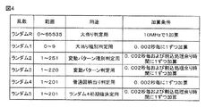
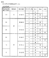
図4は、各乱数を示す説明図である。図4においては、乱数の種別、更新範囲、用途、および、加算条件が示されている。各乱数は、以下のように使用される。 FIG. 4 is an explanatory diagram showing each random number. FIG. 4 shows the type of random number, the update range, the usage, and the addition condition. Each random number is used as follows.
(1)ランダムR:大当りにするか否かを判定する当り判定用のランダムカウンタである。ランダムRは、10MHzで1ずつ更新され、0から加算更新されてその上限である65535まで加算更新された後再度0から加算更新される。(2)ランダム1(MR1):大当りの種類(種別、通常大当り、確変大当り、および、突確大当りのいずれかの種別)および大当り図柄を決定する(大当り種別判定用、大当り図柄決定用)。(3)ランダム2(MR2):変動パターンの種類(種別)を決定する(変動パターン種別判定用)。(4)ランダム3(MR3):変動パターン(変動時間)を決定する(変動パターン判定用)。(5)ランダム4(MR4):普通図柄に基づく当りを発生させるか否か決定する(普通図柄当り判定用)。(6)ランダム5(MR5):ランダム4の初期値を決定する(ランダム4初期値決定用)。 (1) Random R: A random counter for hit determination for determining whether or not to make a big hit. Random R is updated one by one at 10 MHz, is added and updated from 0, and is added and updated to its upper limit of 65535, and then is added and updated again from 0. (2) Random 1 (MR1): Determines the type of jackpot (any type of type, normal jackpot, probability variation jackpot, or sudden hit jackpot) and jackpot symbol (for jackpot type determination, jackpot symbol determination). (3) Random 2 (MR2): The type (type) of the variation pattern is determined (for variation pattern type determination). (4) Random 3 (MR3): A variation pattern (variation time) is determined (for variation pattern determination). (5) Random 4 (MR4): Determines whether or not to generate a hit based on the normal symbol (for normal symbol hit determination). (6) Random 5 (MR5): An initial value of random 4 is determined (for determining a random 4 initial value).
この実施の形態では、特定遊技状態である大当りとして、通常大当り、確変大当り、および、突確大当りという複数の種別が含まれている。したがって、大当り判定用乱数(ランダムR)の値に基づいて、大当りとする決定がされたときには、大当り種別判定用乱数(ランダム1)の値に基づいて、大当りの種別が、これらいずれかの大当り種別に決定される。さらに、大当りの種別が決定されるときに、同時に大当り種別判定用乱数(ランダム1)の値に基づいて、大当り図柄も決定される。したがって、ランダム1は、大当り図柄決定用乱数でもある。 In this embodiment, the big hit that is the specific gaming state includes a plurality of types of normal big hit, probability variation big hit, and sudden hit big hit. Therefore, when the big hit is determined based on the value of the big hit determination random number (random R), the big hit type is determined based on the value of the big hit type determination random number (random 1). Determined by type. Furthermore, when the type of jackpot is determined, the jackpot symbol is also determined based on the value of the jackpot type determination random number (random 1) at the same time. Therefore, random 1 is also a jackpot symbol determining random number.
また、変動パターンは、まず、変動パターン種別判定用乱数(ランダム2)を用いて変動パターン種別を決定し、変動パターン判定用乱数(ランダム3)を用いて、決定した変動パターン種別に含まれるいずれかの変動パターンに決定する。そのように、この実施の形態では、2段階の抽選処理によって変動パターンが決定される。変動パターン種別とは、複数の変動パターンをその変動態様の特徴にしたがってグループ化したものである。変動パターン種別には、1または複数の変動パターンが属している。 In addition, the variation pattern is first determined using the variation pattern type determination random number (random 2), and is included in the determined variation pattern type using the variation pattern determination random number (random 3). To determine the variation pattern. Thus, in this embodiment, the variation pattern is determined by a two-stage lottery process. The variation pattern type is a group of a plurality of variation patterns according to the characteristics of the variation mode. One or more variation patterns belong to the variation pattern type.
この実施の形態では、変動パターンが、リーチを伴なわない変動パターン種別である通常変動パターン種別と、リーチを伴なう変動パターン種別であるリーチ変動パターン種別とに種別分けされている。 In this embodiment, the variation patterns are classified into a normal variation pattern type that is a variation pattern type that does not involve reach and a reach variation pattern type that is a variation pattern type that involves reach.
このような変動パターン種別は、表示結果がはずれとなる場合に、時短状態であるときと、時短状態でないときとで、変動パターン種別の選択割合が異なるように設定されていることにより、時短状態であるときには、時短状態でないときと比べて、変動時間が短縮される。たとえば、時短状態では、時短状態でないときと比べて、変動時間の平均時間を短くするために、変動パターン種別のうち最も変動時間が短い変動パターン種別が選択される割合が高くなり、リーチ種別が選択されるときでも変動パターン種別のうち最も変動時間が短いノーマルリーチの変動パターンが選択される割合が高くなるように設定されることで、時短状態でないときと比べて、変動時間の平均時間が短くなる。 When the display result is out of order, such a variation pattern type is set so that the selection ratio of the variation pattern type is different depending on whether it is in the short-time state or not in the short-time state. When this is the case, the variation time is shortened compared to when the time is not short. For example, in the short-time state, in order to shorten the average time of the fluctuation time compared to the case where the time-short state is not, the ratio of the fluctuation pattern type having the shortest fluctuation time among the fluctuation pattern types is increased, and the reach type is Even when selected, the average time of the fluctuation time is shorter than when not in the short-time state by setting the ratio that the fluctuation pattern of the normal reach with the shortest fluctuation time is selected among the fluctuation pattern types to be higher. Become.
なお、このような変動パターン種別は、変動表示をする特別図柄の保留記憶数(第1特別図柄と第2特別図柄との合算保留記憶数)が所定数以上であるときと、所定数未満であるときとで選択割合が異なるように設定されることにより、変動表示をする各特別図柄の保留記憶数が所定数以上であるときには、各特別図柄の保留記憶数が所定数未満であるときと比べて、変動時間が短縮される保留数短縮制御が実行される。たとえば、保留数短縮制御状態では、保留数短縮制御状態でないときと比べて、通常変動パターン種別のような変動時間が短い変動パターン種別が選択される割合が高くなり、リーチ種別が選択されるときでもノーマルリーチのような変動時間が短いリーチの変動パターンが選択される割合が高くなるように設定されることで、保留数短縮制御状態でないときと比べて、変動時間の平均時間が短くなる。 In addition, such a variation pattern type is less than the predetermined number when the number of reserved memories of the special symbol for which the variation is displayed (the total number of reserved memories of the first special symbol and the second special symbol) is a predetermined number or more. When the number of reserved memories of each special symbol that is variably displayed is greater than or equal to a predetermined number by setting the selection ratio to be different from a certain time, and when the number of reserved memories of each special symbol is less than the predetermined number In comparison, the number-of-holds reduction control that reduces the variation time is executed. For example, in the hold number shortening control state, when the variation pattern type having a short variation time such as the normal variation pattern type is selected and the reach type is selected, compared to the case where the hold number shortening control state is not set. However, the average time of the fluctuation time is shortened by setting the ratio of selection of the fluctuation pattern of the reach having a short fluctuation time such as normal reach to be higher than that in the non-holding number shortening control state.
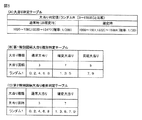
図5は、大当り判定テーブルおよび大当り種別判定テーブルを示す説明図である。図5(A)は、大当り判定テーブルを示す説明図である。大当り判定テーブルとは、ROM54に記憶されているデータの集まりであって、ランダムRと比較される大当り判定値が設定されているテーブルである。大当り判定テーブルには、通常状態(確変状態でない遊技状態、すなわち非確変状態)において用いられる通常時(非確変時)大当り判定テーブルと、確変状態において用いられる確変時大当り判定テーブルとがある。
FIG. 5 is an explanatory diagram showing a jackpot determination table and a jackpot type determination table. FIG. 5A is an explanatory diagram showing a jackpot determination table. The jackpot determination table is a collection of data stored in the
通常時大当り判定テーブルには、図5(A)の左欄に記載されている各数値が大当り判定値として設定され、確変時大当り判定テーブルには、図5(A)の右欄に記載されている各数値が大当り判定値として設定されている。確変時大当り判定テーブルに設定された大当り判定値は、通常時大当り判定テーブルに設定された大当り判定値と共通の大当り判定値(通常時大当り判定値または第1大当り判定値という)に、確変時固有の大当り判定値が加えられたことにより、確変時大当り判定テーブルよりも多い個数(10倍の個数)の大当り判定値(確変時大当り判定値または第2大当り判定値という)が設定されている。これにより、確変状態には、通常状態よりも高い確率で大当りとする判定がなされる。 Each value described in the left column of FIG. 5 (A) is set as a big hit determination value in the normal jackpot determination table, and is described in the right column of FIG. 5 (A) in the probability change big hit determination table. Each value is set as a big hit judgment value. The jackpot judgment value set in the jackpot judgment table at the time of probability change is the jackpot judgment value common to the jackpot judgment value set in the normal jackpot judgment table (referred to as the normal jackpot judgment value or the first jackpot judgment value). Due to the addition of the unique jackpot judgment value, a larger number (10 times the number of jackpot judgment values) than the probability change jackpot judgment table (referred to as the jackpot judgment value or the second jackpot judgment value at the time of probability change) is set. . As a result, the probability variation state is determined to be a big hit with a higher probability than the normal state.
CPU56は、所定の時期に、乱数回路503のカウント値を抽出して抽出値を大当り判定用乱数(ランダムR)の値と比較するのであるが、大当り判定用乱数値が図5(A)に示すいずれかの大当り判定値に一致すると、特別図柄に関して大当り(通常大当り、または、確変大当り)にすることに決定する。なお、図5(A)に示す「確率」は、大当りになる確率(割合)を示す。
The
図5(B),(C)は、ROM54に記憶されている大当り種別判定テーブルを示す説明図である。図5(B)は、遊技球が第1始動入賞口13に入賞したことに基づく保留記憶(第1保留記憶ともいう)を用いて大当り種別を決定する場合(第1特別図柄の変動表示が行なわれるとき)に用いる第1特別図柄大当り種別判定テーブル(第1特別図柄用)である。図5(C)は、遊技球が第2始動入賞口14に入賞したことに基づく保留記憶(第2保留記憶ともいう)を用いて大当り種別を決定する場合(第2特別図柄の変動表示が行なわれるとき)に用いる第2特別図柄大当り種別判定テーブルである。
FIGS. 5B and 5C are explanatory diagrams showing a jackpot type determination table stored in the
図5(B)、および、図5(C)の特別図柄大当り種別判定テーブルのそれぞれは、変動表示結果を大当り図柄にする旨の判定がなされたときに、大当り種別判定用の乱数(ランダム1)に基づいて、大当りの種別を「通常大当り」、「確変大当り」、「突確大当り」のうちのいずれかに決定するとともに、大当り図柄を決定するために参照される。 Each of the special symbol jackpot type determination tables of FIG. 5B and FIG. 5C is a random number (random 1) for determining the jackpot type when it is determined that the variable display result is a jackpot symbol. ), The type of jackpot is determined as one of “normal jackpot”, “probable big hit”, or “probable jackpot”, and is also referred to for determining the jackpot symbol.
図5(B)の第1特別図柄大当り種別判定テーブルには、ランダム1の値と比較される数値であって、「通常大当り」、「確変大当り」、「突確大当り」のそれぞれに対応した判定値(大当り種別判定値)が設定されている。図5(C)の第2特別図柄大当り種別判定テーブルには、ランダム1の値と比較される数値であって、「通常大当り」、「確変大当り」のそれぞれに対応した判定値(大当り種別判定値)が設定されている。 In the first special symbol jackpot type judgment table of FIG. 5 (B), there are numerical values to be compared with the random 1 value, and judgments corresponding to “normal jackpot”, “probable variation jackpot”, and “crash jackpot”. Value (big hit type judgment value) is set. In the second special symbol jackpot type determination table of FIG. 5 (C), there are numerical values to be compared with random 1 values, which are judgment values corresponding to “normal jackpot” and “probable variation jackpot” (jackpot type judgment). Value) is set.
また、図5(B),(C)に示すように、大当り種別判定値は、第1特別図柄および第2特別図柄の大当り図柄を決定する判定値(大当り図柄判定値)としても用いられる。「通常大当り」に対応した判定値は、第1特別図柄および第2特別図柄の大当り図柄の「3」に対応した判定値としても設定されている。「確変大当り」に対応した判定値は、第1特別図柄および第2特別図柄の大当り図柄の「7」に対応した判定値としても設定されている。「突確大当り」に対応した判定値は、第2特別図柄の大当り図柄の「5」に対応した判定値としても設定されている。 Further, as shown in FIGS. 5B and 5C, the big hit type determination value is also used as a determination value (big hit symbol determination value) for determining the big hit symbol of the first special symbol and the second special symbol. The determination value corresponding to “normal jackpot” is also set as the determination value corresponding to “3” of the jackpot symbol of the first special symbol and the second special symbol. The determination value corresponding to “probable big hit” is also set as the determination value corresponding to “7” of the big hit symbol of the first special symbol and the second special symbol. The determination value corresponding to the “surprise big hit” is also set as the determination value corresponding to the big hit symbol “5” of the second special symbol.
このような大当り種別大当り種別判定テーブルを用いて、CPU56は、大当り種別として、ランダム1の値が一致した大当り種別判定値に対応する種別を決定するともに、大当り図柄として、ランダム1の値が一致した大当り図柄を決定する。これにより、大当り種別と、大当り種別に対応する大当り図柄とが同時に決定される。
Using such a jackpot type jackpot type determination table, the
図5(B)の第1特別図柄大当り種別判定テーブルと、図5(C)の第2特別図柄大当り種別判定テーブルとでは、高確率状態となる大当りに決定される割合が同じであるが、第2特別図柄大当り種別判定テーブルの方が、第1特別図柄大当り種別判定テーブルよりも、大当り遊技状態におけるラウンド数が多い大当り(15ラウンドの大当り)が選択される割合が高く、また、大当り遊技状態における実質的な入賞可能数が多い大当り(15ラウンドの大当り)が選択される割合が高い。したがって、第2特別図柄の方が第1特別図柄よりも、大当りとなったときに、大入賞口への入賞に関して遊技者にとって有利度合いが高い(たとえば、実質的に入賞可能なラウンド数が多い、実質的な入賞可能数が多い等)有利状態としての大当り遊技状態に制御される。 In the first special symbol jackpot type determination table in FIG. 5 (B) and the second special symbol jackpot type determination table in FIG. 5 (C), the ratios determined for the jackpots that are in a high probability state are the same. The second special symbol jackpot type determination table has a higher ratio of selection of big hits (15 round big hits) with a larger number of rounds in the big hit gaming state than the first special symbol jackpot type determination table, and the jackpot game There is a high ratio of selecting big hits (15 round big hits) with a substantial number of possible winnings in the state. Therefore, when the second special symbol is a big hit than the first special symbol, the player has a higher degree of advantage with respect to winning the big prize opening (for example, there are substantially more rounds that can be won). The game is controlled to a big hit gaming state as an advantageous state.
なお、この実施の形態では、図5(C)の第2特別図柄大当り種別判定テーブルにおいて、突確大当りが選択されない例を示した。しかし、これに限らず、図5(C)の第2特別図柄大当り種別判定テーブルにおいては、突確大当りが選択可能であるが、図5(B)の第1特別図柄大当り種別判定テーブルよりも突確大当りの選択割合が高くなるようにデータを設定してもよい。 In the present embodiment, an example is shown in which the sudden big hit is not selected in the second special symbol big hit type determination table of FIG. However, the present invention is not limited to this, and in the second special symbol jackpot type determination table of FIG. 5C, the abrupt big hit can be selected, but more accurate than the first special symbol jackpot type determination table of FIG. 5B. Data may be set so that the selection ratio for jackpots is high.
図6は、遊技制御用マイクロコンピュータ560が送信する演出制御コマンドの内容の一例を示す説明図である。図6においては、演出制御コマンドについて具体的なコマンドデータと、コマンドの名称およびコマンドの指定内容との関係が示されている。演出制御コマンドの遊技制御用マイクロコンピュータ560においては、図6に示すように、遊技制御状態に応じて、各種の演出制御コマンドを演出制御用マイクロコンピュータ100へ送信する。
FIG. 6 is an explanatory diagram showing an example of the contents of the effect control command transmitted by the game control microcomputer 560. FIG. 6 shows specific command data regarding the effect control command, and the relationship between the name of the command and the designated content of the command. In the game control microcomputer 560 for effect control commands, various effect control commands are transmitted to the
図6のうち、主なコマンドを説明する。コマンド80XX(H)は、特別図柄の変動表示に対応して演出表示装置9において変動表示される演出図柄の変動パターンを指定する演出制御コマンド(変動パターンコマンド)である(それぞれ変動パターンXXに対応)。複数の変動パターンのそれぞれに対して一意な番号を付した場合に、その番号で特定される変動パターンのそれぞれに対応する変動パターンコマンドがある。「(H)」は16進数であることを示す。また、変動パターンを指定する演出制御コマンドは、変動開始を指定するためのコマンドでもある。したがって、演出制御用CPU101は、コマンド80XX(H)を受信すると、演出表示装置において演出図柄の変動表示を開始するように制御する。
Main commands in FIG. 6 will be described. The command 80XX (H) is an effect control command (variation pattern command) for designating a variation pattern of the effect symbol that is variably displayed on the
コマンド8C01(H)〜8C04(H)は、大当りとするか否か、および大当り種別を示す表示結果指定コマンドである。 Commands 8C01 (H) to 8C04 (H) are display result designation commands indicating whether or not to make a big hit and the type of big hit.
コマンド8D01(H)は、第1特別図柄の変動表示を開始することを示す第1図柄変動指定コマンドである。コマンド8D02(H)は、第2特別図柄の変動表示を開始することを示す第2図柄変動指定コマンドである。コマンド8F00(H)は、第1,第2特別図柄の変動を終了することを指定するコマンド(図柄確定指定コマンド)である。 The command 8D01 (H) is a first symbol variation designation command indicating that the variation display of the first special symbol is started. Command 8D02 (H) is a second symbol variation designation command indicating that the variation display of the second special symbol is started. The command 8F00 (H) is a command (design determination designation command) for designating to end the variation of the first and second special symbols.
コマンド95XX(H)は、始動入賞が生じたときの入賞時判定結果の内容を示すコマンド(入賞時判定結果指定コマンド)であり、入賞時判定結果のうち、大当りとなるか否か、および、大当りの種別の等の所定種類の判定結果を示すものである。 The command 95XX (H) is a command (a winning determination result designation command) indicating the contents of the winning determination result when the start winning is generated, and whether or not the winning determination result is a big hit, It shows the determination result of a predetermined type such as the type of jackpot.
次に、パチンコ遊技機1の動作について説明する。パチンコ遊技機1においては、主基板31における遊技制御用マイクロコンピュータ560が予め定められたメイン処理を実行すると、所定時間(たとえば2ms)毎に定期的にタイマ割込がかかりタイマ割込処理が実行されることにより、各種の遊技制御が実行可能となる。
Next, the operation of the
メイン処理においては、たとえば、必要な初期設定処理、通常時の初期化処理、通常時以外の遊技状態復旧処理、乱数回路設定処理(乱数回路503を初期設定)、表示用乱数更新処理(変動パターンの種別決定、変動パターン決定等の各種乱数の更新処理)、および、初期値用乱数更新処理(普通図柄当り判定用乱数発生カウンタのカウント値の初期値の更新処理)等が実行される。
In the main processing, for example, necessary initial setting processing, normal time initialization processing, game state restoration processing other than normal time, random number circuit setting processing (
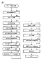
図7は、タイマ割込処理を示すフローチャートである。タイマ割込が発生すると、CPU56は、図7に示すステップS(以下、単に「S」と示す)20〜S34のタイマ割込処理を実行する。タイマ割込処理において、まず、電源断信号が出力されたか否か(オン状態になったか否か)を検出する電源断検出処理を実行する(S20)。次いで、入力ドライバ回路58を介して、ゲートスイッチ32a、第1始動口スイッチ13a、第2始動口スイッチ14aおよびカウントスイッチ23の検出信号を入力し、それらの状態判定を行なう(スイッチ処理:S21)。
FIG. 7 is a flowchart showing the timer interrupt process. When the timer interrupt occurs, the
次に、CPU56は、第1特別図柄表示器8a、第2特別図柄表示器8b、普通図柄表示器10、第1特別図柄保留記憶表示器18a、第2特別図柄保留記憶表示器18b、普通図柄保留記憶表示器41の表示制御を行なう表示制御処理を実行する(S22)。第1特別図柄表示器8a、第2特別図柄表示器8bおよび普通図柄表示器10については、S32,S33で設定される出力バッファの内容に応じて各表示器に対して駆動信号を出力する制御を実行する。
Next, the
また、遊技制御に用いられる普通図柄当り判定用乱数および大当り種別判定用乱数等の各判定用乱数を生成するための各カウンタのカウント値を更新する処理を行なう(判定用乱数更新処理:S23)。CPU56は、さらに、初期値用乱数および表示用乱数を生成するためのカウンタのカウント値を更新する処理を行なう(初期値用乱数更新処理,表示用乱数更新処理:S24,S25)。
In addition, a process of updating the count value of each counter for generating each determination random number such as a normal symbol determination random number and a big hit type determination random number used for game control is performed (determination random number update process: S23). . The
さらに、CPU56は、特別図柄プロセス処理を行なう(S26)。特別図柄プロセス処理では、第1特別図柄表示器8a、第2特別図柄表示器8b、および、大入賞口を所定の順序で制御するための特別図柄プロセスフラグにしたがって該当する処理を実行し、特別図柄プロセスフラグの値を、遊技状態に応じて更新する。
Further, the
次いで、普通図柄プロセス処理を行なう(S27)。普通図柄プロセス処理では、CPU56は、普通図柄表示器10の表示状態を所定の順序で制御するための普通図柄プロセスフラグにしたがって該当する処理を実行し、普通図柄プロセスフラグの値を、遊技状態に応じて更新する。
Next, the normal symbol process is performed (S27). In the normal symbol process, the
また、CPU56は、演出制御用マイクロコンピュータ100に演出制御コマンドを送出する処理を行なう(演出制御コマンド制御処理:S28)。さらに、CPU56は、たとえばホール管理用コンピュータに供給される大当り情報、始動情報、確率変動情報等のデータを出力する情報出力処理を行なう(S29)。
Further, the
また、CPU56は、第1始動口スイッチ13a、第2始動口スイッチ14aおよびカウントスイッチ23の検出信号に基づく賞球個数の設定等を行なう賞球処理を実行する(S30)。
Further, the
この実施の形態では、出力ポートの出力状態に対応したRAM領域(出力ポートバッファ)が設けられているのであるが、CPU56は、出力ポートの出力状態に対応したRAM領域におけるソレノイドのオン/オフに関する内容を出力ポートに出力する(S31:出力処理)。
In this embodiment, a RAM area (output port buffer) corresponding to the output state of the output port is provided. However, the
また、CPU56は、特別図柄プロセスフラグの値に応じて特別図柄の演出表示を行なうための特別図柄表示制御データを特別図柄表示制御データ設定用の出力バッファに設定する特別図柄表示制御処理を行なう(S32)。
Further, the
さらに、CPU56は、普通図柄プロセスフラグの値に応じて普通図柄の演出表示を行なうための普通図柄表示制御データを普通図柄表示制御データ設定用の出力バッファに設定する普通図柄表示制御処理を行なう(S33)。また、CPU56は、出力バッファに設定された表示制御データに応じて、S22において駆動信号を出力することによって、普通図柄表示器10における普通図柄の演出表示を実行する。
Further, the
その後、割込許可状態に設定し(S34)、処理を終了する。以上の制御によって、この実施の形態では、遊技制御処理は所定時間毎に起動されることになる。 Thereafter, the interrupt permission state is set (S34), and the process ends. With the above control, in this embodiment, the game control process is started every predetermined time.
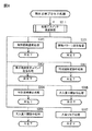
図8は、特別図柄プロセス処理(S26)を示すフローチャートである。特別図柄プロセス処理では、第1特別図柄表示器8aまたは第2特別図柄表示器8bおよび大入賞口を制御するための処理が実行される。特別図柄プロセス処理においては、始動口スイッチ通過処理を実行する(S311)。そして、内部状態に応じて、S300〜S307のうちのいずれかの処理を行なう。
FIG. 8 is a flowchart showing the special symbol process (S26). In the special symbol process, a process for controlling the first
遊技制御用マイクロコンピュータ560において、RAM55には、第1始動入賞口13への始動入賞に基づいて得られる大当り判定用乱数等の保留記憶データ(第1保留記憶データ)が記憶される第1保留記憶バッファと、第2始動入賞口14への始動入賞に基づいて得られる大当り判定用乱数等の保留記憶データ(第2保留記憶データ)が記憶される第2保留記憶バッファとが設けられている。これら各保留記憶バッファには、各保留記憶の記憶数の上限値(この例では4)に対応した保存領域が確保されている。
In the game control microcomputer 560, the
始動口スイッチ通過処理では、第1始動口スイッチ13aがオンしていれば、第1保留記憶数が上限値(たとえば、4)に達していないことを条件として、第1保留記憶データの記憶数を計数する第1保留記憶数カウンタの値を1増やし、乱数回路503やソフトウェア乱数を生成するためのカウンタから数値データ(たとえば、大当り判定用乱数、変動パターン種別判定用乱数、および、変動パターン判定用乱数)を抽出し、それらを、第1保留記憶バッファにおける保存領域に保存(格納)する処理を実行する。一方、第2始動口スイッチ14aがオンしていれば、第2保留記憶数が上限値(たとえば、4)に達していないことを条件として、第2保留記憶データの記憶数を計数する第2保留記憶数カウンタの値を1増やし、乱数回路503やソフトウェア乱数を生成するためのカウンタから数値データ(たとえば、大当り判定用乱数、変動パターン種別判定用乱数、および、変動パターン判定用乱数)を抽出し、それらを、第2保留記憶バッファにおける保存領域に保存(格納)する処理を実行する。
In the start port switch passing process, if the first
以下の保留記憶に関する説明に関しては、第1保留記憶バッファまたは第2保留記憶バッファに前述のような始動入賞に関する情報が記憶されることを「保留記憶される」と示す場合がある。また、第1保留記憶バッファに記憶される数値データを第1保留記憶情報と呼び、第2保留記憶バッファに記憶される数値データを第2保留記憶情報と呼ぶ場合がある。 With respect to the following description regarding the hold storage, the fact that the information related to the start winning as described above is stored in the first hold storage buffer or the second hold storage buffer may be indicated as “hold stored”. In addition, numerical data stored in the first reserved storage buffer may be referred to as first reserved storage information, and numerical data stored in the second reserved storage buffer may be referred to as second reserved storage information.
S300〜S307の処理は、以下のような処理である。特別図柄通常処理(S300)は、変動表示の表示結果を大当りとするか否かの決定、および、大当りとする場合の大当り種別の決定等を行なう処理である。変動パターン設定処理(S301)は、変動パターンの決定、および、決定された変動パターンに応じて変動時間を計時するための変動時間タイマの計時開始等の制御を行なう処理である。 The processing of S300 to S307 is as follows. The special symbol normal process (S300) is a process for determining whether or not the display result of the variable display is a big hit, and determining the big hit type in the case of the big hit. The variation pattern setting process (S301) is a process for performing control such as determination of a variation pattern and start of timing of a variation time timer for measuring variation time according to the determined variation pattern.
表示結果指定コマンド送信処理(S302)は、演出制御用マイクロコンピュータ100に、表示結果指定コマンドを送信する制御を行なう処理である。特別図柄変動中処理(S303)は、変動パターン設定処理で選択された変動パターンの変動時間が経過すると特別図柄停止処理にプロセスを進める処理である。特別図柄停止処理(S304)は、決定された変動パターンに対応する変動時間の経過が変動時間タイマにより計時されたときに第1特別図柄表示器8aまたは第2特別図柄表示器8bにおける変動表示を停止して停止図柄を導出表示させる処理である。
The display result designation command transmission process (S302) is a process for performing control to transmit a display result designation command to the
大入賞口開放前処理(S305)は、大当りの種別に応じて、特別可変入賞球装置20において大入賞口を開放する制御等を行なう処理である。大入賞口開放中処理(S306)は、大当り遊技状態中のラウンド表示の演出制御コマンドを演出制御用マイクロコンピュータ100に送信する制御や大入賞口の閉成条件の成立を確認する処理等を行なう処理である。大入賞口の閉成条件が成立し、かつ、まだ残りラウンドがある場合には、大入賞口開放前処理に移行する。また、全てのラウンドを終えた場合には、大当り終了処理に移行する。大当り終了処理(S307)は、大当り遊技状態が終了したことを遊技者に報知する表示制御を演出制御用マイクロコンピュータ100に行なわせるための制御等を行なう処理である。
The big winning opening opening pre-processing (S305) is a process of performing control for opening the big winning opening in the special variable winning
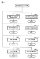
図9は、特別図柄プロセス処理における特別図柄通常処理(S300)を示すフローチャートである。特別図柄通常処理において、CPU56は、第1保留記憶バッファまたは第2保留記憶バッファに保留記憶データがあるかどうかを確認する(S51)。第1保留記憶バッファおよび第2保留記憶バッファのどちらにも保留記憶データがない場合には、処理を終了する。
FIG. 9 is a flowchart showing the special symbol normal process (S300) in the special symbol process. In the special symbol normal process, the
第1保留記憶バッファまたは第2保留記憶バッファに保留記憶データがあるときには、CPU56は、第2保留記憶バッファの方に保留記憶データがあるか否か確認する(S52)。第2保留記憶バッファに保留記憶データがあれば、特別図柄ポインタ(第1特別図柄について特別図柄プロセス処理を行なっているのか第2特別図柄について特別図柄プロセス処理を行なっているのかを示すフラグ)に「第2」を示すデータを設定する(S54)。一方、第2保留記憶バッファに保留記憶データがなければ、特別図柄ポインタに「第1」を示すデータを設定する(S53)。
When there is pending storage data in the first pending storage buffer or the second pending storage buffer, the
この実施の形態では、以下、特別図柄ポインタに「第1」を示すデータが設定されたか「第2」を示すデータが設定されたかに応じて、第1特別図柄表示器8aにおける第1特別図柄の変動表示と、第2特別図柄表示器8bにおける第2特別図柄の変動表示とを、共通の処理ルーチンを用いて実行する。特別図柄ポインタに「第1」を示すデータが設定されたときには、第1保留記憶バッファに記憶された保留記憶データに基づいて、第1特別図柄表示器8aにおける第1特別図柄の変動表示が行なわれる。一方、特別図柄ポインタに「第2」を示すデータが設定されたときには、第2保留記憶バッファに記憶された保留記憶データに基づいて、第2特別図柄表示器8bにおける第2特別図柄の変動表示が行なわれる。
In this embodiment, hereinafter, the first special symbol on the first
S52〜S54の制御により、第2保留記憶バッファ内に第2保留記憶のデータが1つでも存在すれば、その第2保留記憶のデータに基づいた第2特別図柄表示器8bの変動表示が、第1保留記憶のデータに基づいた第1特別図柄表示器8aの変動表示に優先して実行される。つまり、第2特別図柄の変動表示を開始するための第2の開始条件は、第1特別図柄の変動表示を開始するための第1の開始条件よりも優先的に成立する。
If there is at least one second reserved memory data in the second reserved memory buffer by the control of S52 to S54, the fluctuation display of the second
次いで、CPU56は、RAM55において、特別図柄ポインタが示す方の保留記憶数=1に対応する保存領域に格納されている各乱数値を読出してRAM55の保留記憶バッファに格納する(S55)。具体的には、CPU56は、特別図柄ポインタが「第1」を示している場合には、第1保留記憶バッファにおける第1保留記憶数=1に対応する保存領域に格納されている各乱数値を読出してRAM55の保留記憶バッファに格納する。また、CPU56は、特別図柄ポインタが「第2」を示している場合には、第2保留記憶バッファにおける第2保留記憶数=1に対応する保存領域に格納されている各乱数値を読出してRAM55の保留記憶バッファに格納する。
Next, the
そして、CPU56は、特別図柄ポインタが示す方の保留記憶数カウンタのカウント値を1減算し、かつ、各保存領域の内容をシフトする(S56)。具体的には、CPU56は、特別図柄ポインタが「第1」を示している場合には、第1保留記憶数カウンタのカウント値を1減算し、かつ、第1保留記憶バッファにおける各保存領域の内容をシフトする。また、特別図柄ポインタが「第2」を示している場合に、第2保留記憶数カウンタのカウント値を1減算し、かつ、第2保留記憶バッファにおける各保存領域の内容をシフトする。
Then, the
すなわち、CPU56は、特別図柄ポインタが「第1」を示している場合に、RAM55の第1保留記憶バッファにおいて第1保留記憶数=n(n=2,3,4)に対応する保存領域に格納されている各乱数値を、第1保留記憶数=n−1に対応する保存領域に格納する。また、特別図柄ポインタが「第2」を示す場合に、RAM55の第2保留記憶バッファにおいて第2保留記憶数=n(n=2,3,4)に対応する保存領域に格納されている各乱数値を、第2保留記憶数=n−1に対応する保存領域に格納する。
That is, when the special symbol pointer indicates “first”, the
よって、各第1保留記憶数(または、各第2保留記憶数)に対応するそれぞれの保存領域に格納されている各乱数値が抽出された順番は、常に、第1保留記憶数(または、第2保留記憶数)=1,2,3,4の順番と一致するようになっている。 Therefore, the order in which each random value stored in each storage area corresponding to each first reserved memory number (or each second reserved memory number) is extracted is always the first reserved memory number (or (Second reserved storage number) = 1, 2, 3, 4 in order.
RAM55に形成され合算保留記憶数を計数する合計保留記憶数カウンタのカウント値を1減算する(S57)。なお、CPU56は、カウント値が1減算される前の合算保留記憶数カウンタの値をRAM55の所定の領域に保存する。
One is subtracted from the count value of the total pending memory number counter formed in the
また、CPU56は、減算後の特別図柄ポインタが示す方の保留記憶数カウンタの値に基づいて、特別図柄ポインタが示す方の保留記憶数指定コマンドを演出制御用マイクロコンピュータ100に送信する制御を行なう(S59)。この場合、特別図柄ポインタに「第1」を示す値が設定されている場合には、CPU56は、第1保留記憶数指定コマンドを送信する制御を行なう。また、特別図柄ポインタに「第2」を示す値が設定されている場合には、CPU56は、第2保留記憶数指定コマンドを送信する制御を行なう。
Further, the
特別図柄通常処理では、最初に、第1始動入賞口13を対象として処理を実行することを示す「第1」を示すデータすなわち第1特別図柄を対象として処理を実行することを示す「第1」を示すデータ、または第2始動入賞口14を対象として処理を実行することを示す「第2」を示すデータすなわち第2特別図柄を対象として処理を実行することを示す「第2」を示すデータが、特別図柄ポインタに設定される。そして、特別図柄プロセス処理における以降の処理では、特別図柄ポインタに設定されているデータに応じた処理が実行される。よって、S300〜S307の処理を、第1特別図柄を対象とする場合と第2特別図柄を対象とする場合とで共通化することができる。
In the special symbol normal process, first, data indicating “first” indicating that the process is executed for the first
次いで、CPU56は、保留記憶バッファからランダムR(大当り判定用乱数)を読出し、大当り判定モジュールを実行する(S60)。なお、この場合、CPU56は、始動口スイッチ通過処理のS214や始動口スイッチ通過処理のS224で抽出し第1保留記憶バッファや第2保留記憶バッファに予め格納した大当り判定用乱数を読出し、大当り判定を行なう。大当り判定モジュールは、予め決められている大当り判定値(図5参照)と大当り判定用乱数とを比較し、それらが一致したら大当りとすることに決定する処理を実行するプログラムである。すなわち、大当り判定の処理を実行するプログラムである。
Next, the
大当り判定の処理では、遊技状態が確変状態(高確率状態)の場合は、遊技状態が非確変状態(通常遊技状態)の場合よりも、大当りとなる確率が高くなるように構成されている。具体的には、予め大当り判定値の数が多く設定されている確変時大当り判定テーブル(ROM54における図5(A)の右側の数値が設定されているテーブル)と、大当り判定値の数が確変時大当り判定テーブルよりも少なく設定されている通常時大当り判定テーブル(ROM54における図5(A)の左側の数値が設定されているテーブル)とが設けられている。そして、CPU56は、遊技状態が確変状態であるか否かを確認し、遊技状態が確変状態であるときは、確変時大当り判定テーブルを使用して大当りの判定の処理を行ない、遊技状態が通常遊態や時短状態であるときは、通常時大当り判定テーブルを使用して大当りの判定の処理を行なう。すなわち、CPU56は、大当り判定用乱数(ランダムR)の値が図5(A)に示すいずれかの大当り判定値に一致すると、特別図柄に関して大当りとすることに決定する。大当りとすることに決定した場合には(S60)、S71に移行する。なお、大当りとするか否か決定するということは、大当り遊技状態に移行させるか否か決定するということであるが、特別図柄表示器における停止図柄を大当り図柄とするか否か決定するということでもある。
The jackpot determination process is configured such that when the gaming state is in a probable change state (high probability state), the probability of winning a big hit is higher than in the case where the gaming state is a non-probability change state (normal game state). Specifically, a probability change jackpot determination table (a table in which the numerical values on the right side of FIG. 5A in the
なお、現在の遊技状態が確変状態であるか否かの確認は、確変フラグがセットされているか否かにより行なわれる。確変フラグは、遊技状態を確変状態に移行するときにセットされ、確変状態を終了するときにリセットされる。具体的に、確変フラグは、大当り遊技を終了する処理においてセットされ、その後、所定回数(100回)の変動表示が行なわれたという条件と、次回の大当りが決定されたという条件といずれか早い方の条件が成立したときに、特別図柄の変動表示を終了して停止図柄を停止表示するタイミングでリセットされる。 Note that whether or not the current gaming state is the probability variation state is determined by whether or not the probability variation flag is set. The probability variation flag is set when the gaming state is shifted to the probability variation state, and is reset when the probability variation state is terminated. Specifically, the probability variation flag is set in the process of ending the big hit game, and then the condition that the predetermined number of times (100 times) of the fluctuation display is performed, or the condition that the next big hit is determined, whichever comes first. When this condition is satisfied, the change display of the special symbol is terminated and the stop symbol is reset at the timing to stop display.
大当り判定用乱数(ランダムR)の値がいずれの大当り判定値にも一致しなければ(S60のN)、後述するS75に進む。 If the value of the jackpot determination random number (random R) does not match any of the jackpot determination values (N in S60), the process proceeds to S75 described later.
S60において大当り判定用乱数(ランダムR)の値がいずれかの大当り判定値に一致すればCPU56は、大当りであることを示す大当りフラグをセットする(S71)。なお、大当りフラグは、大当り遊技が終了するときにリセットされる。そして、大当り種別を複数種類のうちのいずれかに決定するために使用するテーブルとして、図5(B)の第1特別図柄大当り種別判定用テーブルおよび図5(C)の第2特別図柄大当り種別判定用テーブルのうち、いずれかのテーブルを選択する(S72)。具体的に、CPU56は、特別図柄ポインタが「第1」を示している場合には、図5(B)に示す第1特別図柄大当り種別判定用テーブルを選択する。
If the value of the big hit determination random number (random R) coincides with any of the big hit determination values in S60, the
また、CPU56は、特別図柄ポインタが「第2」を示している場合において、図5(C)の第2特別図柄大当り種別判定用テーブルを選択する。
When the special symbol pointer indicates “second”, the
次いで、CPU56は、始動口スイッチ通過処理で抽出し第1保留記憶バッファや第2保留記憶バッファに予め格納した大当り種別判定用乱数を読出し、S72で選択した大当り種別判定テーブルを用いて、保留記憶バッファに格納された大当り種別判定用の乱数(ンダム1)の値と一致する値に対応した大当り種別および大当り図柄を決定する(S73)。
Next, the
図5(B),(C)に示すように、第1特別図柄および第2特別図柄については、大当り種別ごとに大当り図柄が異なるように大当り種別と大当り図柄との関係が設定されており、大当り種別と大当り図柄とが同時に決定されるので、大当り図柄と、大当り種別に応じた遊技制御との対応関係が単純化するため、遊技制御の複雑化を防ぐことができる。 As shown in FIGS. 5B and 5C, for the first special symbol and the second special symbol, the relationship between the big hit type and the big hit symbol is set so that the big hit type is different for each big hit type, Since the big hit type and the big hit symbol are determined at the same time, the correspondence between the big hit symbol and the game control corresponding to the big hit type is simplified, so that the game control can be prevented from becoming complicated.
また、CPU56は、決定した大当りの種別を示す大当り種別データをRAM55における大当り種別バッファに設定する(S74)。たとえば、大当り種別が「通常大当り」の場合には、大当り種別データとして「01」が設定される。大当り種別が「確変大当り」の場合には、大当り種別データとして「02」が設定される。大当り種別が「突確大当り」の場合には、大当り種別データとして「03」が設定される。
Further, the
次いで、CPU56は、特別図柄の停止図柄を設定する(S75)。具体的には、大当りフラグがセットされていない場合には、はずれ図柄となる「−」を特別図柄の停止図柄として設定する。大当りフラグがセットされている場合には、大当り種別の決定結果に応じて、S73により決定された大当り図柄を特別図柄の停止図柄に設定する。すなわち、大当り種別が「通常大当り」に決定されたときには「3」を特別図柄の停止図柄に設定する。大当り種別が「確変大当り」に決定した場合には「7」を特別図柄の停止図柄に決定する。大当り種別が「突確大当り」に決定した場合には「5」を特別図柄の停止図柄に決定する。
Next, the
そして、特別図柄プロセスフラグの値を変動パターン設定処理(S301)に対応した値に更新する(S76)。 Then, the value of the special symbol process flag is updated to a value corresponding to the variation pattern setting process (S301) (S76).
前述した変動パターン設定処理(S301)においては、CPU56が、決定されている大当りの種類、または、はずれに応じて設けられた変動パターンを選択決定するための変動パターン種別決定用のデータテーブル、および、変動パターン決定用のデータテーブル(ROM54に記憶されているデータテーブル)を遊技状態に応じて選択的に用い、変動パターン種別決定用のランダムカウンタの値に基づいて変動パターン種別を選択決定し、変動パターン決定用のランダムカウンタの値に基づいて変動パターンを選択決定する。
In the above-described variation pattern setting process (S301), the
変動パターン設定処理で選択決定される変動パターンには、ノーマルリーチでリーチはずれとなるときの変動パターン、スーパーリーチでリーチはずれとなるときの変動パターン、非リーチはずれとなるときの変動パターン、ノーマルリーチで確変大当りまたは通常大当りとなるときの変動パターン、スーパーリーチで確変大当りまたは通常大当りとなるときの変動パターン、および、突確大当りとなるときの変動パターン等の各種の変動パターンが含まれている。ここで、リーチはずれとは、リーチとなった後にはずれ表示結果となることをいう。また、非リーチはずれとは、リーチとならずにはずれ表示結果となることをいう。そして、変動パターン設定処理(S301)においては、選択決定された変動パターンを指定する変動パターン指定コマンドが送信される。 The variation pattern selected and determined in the variation pattern setting process is the variation pattern when the reach is out of normal reach, the variation pattern when the reach is out of super reach, the variation pattern when out of non-reach, and the probability pattern with normal reach Various variation patterns are included such as a variation pattern when a big hit or a normal big hit, a variation pattern when a probable big hit or a normal big hit in super reach, and a variation pattern when a sudden big hit is reached. Here, “reach miss” means that a reach display result is obtained after reaching reach. Further, non-reach out means that the result of display is out of reach without reaching reach. In the variation pattern setting process (S301), a variation pattern designation command for designating the variation pattern selected and determined is transmitted.
前述した表示結果指定コマンド送信処理(S302)においては、CPU56が、決定されている大当りの種類、または、はずれに応じて、表示結果を指定する表示結果1指定〜表示結果4指定コマンドのいずれかの演出制御コマンド(図6参照)を送信する制御を行なう。
In the display result designation command transmission process (S302) described above, the
また、前述した特別図柄変動中処理(S303)においては、CPU56は、変動時間タイマを1減算し、変動時間タイマがタイムアウトしたら、特別図柄プロセスフラグの値を特別図柄停止処理(S304)に対応した値に更新し、特別図柄停止処理に進む。
In the special symbol changing process (S303) described above, the
そして、特別図柄変動停止処理(S304)においては、図柄確定指定コマンドを送信した後、大当りとすることが決定されているときには、特別図柄プロセスフラグの値を大入賞口開放前処理(S305)に対応した値に更新し大入賞口開放前処理に進み、一方、はずれとすることが決定されているときには、特別図柄プロセスフラグの値を特別図柄通常処理(S300)に対応した値に更新し大入賞口開放前処理に進む。また、本実施の形態では、確変状態が変動表示100回が実行されるまで継続するので、変動表示回数を計数するための処理が特別図柄変動停止処理において行なわれる。 Then, in the special symbol variation stop process (S304), if it is determined that a big hit will be made after the symbol confirmation designation command is transmitted, the value of the special symbol process flag is set to the big winning opening opening pre-processing (S305). The value is updated to the corresponding value, and the process proceeds to the pre-opening process for the big prize opening. On the other hand, when it is determined to be off, the special symbol process flag value is updated to a value corresponding to the special symbol normal process (S300). Proceed to the pre-opening process. Further, in the present embodiment, since the probability variation state continues until the variation display is executed 100 times, the process for counting the number of variation displays is performed in the special symbol variation stop process.
また、通常大当り、確変大当り、または、突確大当りすることが決定されたときには、大入賞口開放前処理、大入賞口開放前処理、および、大当り終了処理により大当り遊技状態の制御が行われる。確変大当りまたは突確大当りとすることが決定されたときは、大当り終了処理において、確変フラグおよび時短フラグがセットされることにより、確変状態および時短状態に制御されることとなる。 When it is determined that a normal big hit, a probable big hit, or a sudden big hit is determined, the big win gaming state control is performed by the big winning opening opening pre-processing, the big winning opening opening pre-processing, and the big winning end processing. When it is determined that the probability variation big hit or the sudden big hit is determined, the probability variation flag and the time reduction flag are set in the big hit end process, whereby the probability variation state and the time reduction state are controlled.
次に、演出制御手段としての演出制御用マイクロコンピュータ100の動作を説明する。図10は、演出制御基板80に搭載されている演出制御用マイクロコンピュータ100(具体的には、演出制御用CPU101)が実行する演出制御メイン処理を示すフローチャートである。
Next, the operation of the
演出制御基板80では、電源基板等から電源電圧の供給を受けると、演出制御用CPU101が起動して、図10のフローチャートに示すような演出制御メイン処理を実行する。図10に示す演出制御メイン処理を開始すると、演出制御用CPU101は、まず、所定の初期化処理を実行して(S701)、RAM103のクリアや各種初期値の設定、また演出制御基板80に搭載されたCTC(カウンタ/タイマ回路)のレジスタ設定等を行なう。その後、タイマ割込みフラグがオンとなっているか否かの判定を行なう(S702)。タイマ割込みフラグは、たとえばCTCのレジスタ設定に基づき、所定時間(たとえば2ミリ秒)が経過するごとにオン状態にセットされる。このとき、タイマ割込みフラグがオフであれば(S702のN)、S702の処理を繰り返し実行して待機する。
In the
また、演出制御基板80の側では、所定時間が経過するごとに発生するタイマ割込みとは別に、主基板31から演出制御コマンドを受信するための割込みが発生する。この割込みは、たとえば主基板31からの演出制御INT信号がオン状態となることにより発生する割込みである。演出制御INT信号がオン状態となることによる割込みが発生すると、演出制御用CPU101は、自動的に割込み禁止に設定するが、自動的に割込み禁止状態にならないCPUを用いている場合には、割込み禁止命令(DI命令)を発行することが望ましい。演出制御用CPU101は、演出制御INT信号がオン状態となることによる割込みに対応して、たとえば所定のコマンド受信割込み処理を実行する。このコマンド受信割込み処理では、I/Oに含まれる入力ポートのうちで、中継基板77を介して主基板31から送信された制御信号を受信する所定の入力ポートより、演出制御コマンドとなる制御信号を取込む。このとき取込まれた演出制御コマンドは、たとえば演出制御基板80に搭載されたRAM103における演出制御バッファ設定部に設けられた演出制御コマンド受信用バッファに格納する。一例として、演出制御コマンドが2バイト構成である場合には、1バイト目(MODE)と2バイト目(EXT)を順次に受信して演出制御コマンド受信用バッファに格納する。その後、演出制御用CPU101は、割込み許可に設定してから、コマンド受信割込み処理を終了する。
On the side of the
S702でタイマ割込みフラグがオンである場合には(S702のY)、タイマ割込みフラグをクリアしてオフ状態にするとともに(S703)、コマンド解析処理を実行する(S704)。遊技制御用マイクロコンピュータ560から送信された演出制御コマンドは、たとえば演出制御基板80に搭載されたRAM103における演出制御バッファ設定部に設けられた演出制御コマンド受信用バッファに格納する。一例として、演出制御コマンドが2バイト構成である場合には、1バイト目(MODE)と2バイト目(EXT)を順次に受信して演出制御コマンド受信用バッファに格納する。たとえば、始動入賞時受信コマンドバッファ(始動入賞時コマンド格納領域)を構成するデータが、演出制御バッファ設定部の所定領域に記憶される。始動入賞時受信コマンドバッファは、第1保留記憶情報に対応するデータを記憶する第1保留記憶用バッファと、第2保留記憶情報に対応するデータを記憶する第2保留記憶用バッファとを含む。第1保留記憶用バッファおよび第2保留記憶用バッファの各々は、保留記憶数の最大値(例えば「4」)に対応した格納領域(バッファ番号「1」〜「4」に対応した領域)が設けられている。
If the timer interrupt flag is on in S702 (Y in S702), the timer interrupt flag is cleared and turned off (S703), and command analysis processing is executed (S704). The effect control command transmitted from the game control microcomputer 560 is stored, for example, in an effect control command reception buffer provided in the effect control buffer setting unit in the
第1始動入賞口や第2始動入賞口への始動入賞があったときには、第1始動入賞指定コマンド、第2始動入賞指定コマンド、第1保留記憶数指定コマンド、第2保留記憶数指定コマンド等のコマンドが、主基板31から演出制御基板80へと送信される。
When there is a start prize at the first start prize slot or the second start prize slot, a first start prize designation command, a second start prize designation command, a first reserved memory number designation command, a second reserved memory number designation command, etc. Is transmitted from the
演出制御用CPU101は、始動入賞時に送信されるコマンドを受信したときに、第1始動入賞指定コマンドと第2始動入賞指定コマンドとのいずれであるかに基づいて、第1保留記憶情報に関するデータであるか、第2保留記憶情報に関するデータであるかを判断することにより、第1保留記憶用バッファと第2保留記憶用バッファとに振分け、始動入賞時に受信した順番で入賞時判定結果指定コマンドを、始動入賞時受信コマンドバッファの空き領域に格納していく。これにより、第1保留記憶情報に関しては、コマンド受信が正常に行なわれれば、第1保留記憶用バッファのバッファ番号「1」〜「4」のそれぞれに対応する格納領域にコマンドが格納されていく。また、第2保留記憶情報に関しては、コマンド受信が正常に行なわれれば、第2保留記憶用バッファのバッファ番号「1」〜「4」のそれぞれに対応する格納領域にコマンドが格納されていく。
The
第1保留記憶用バッファおよび第2保留記憶用バッファのそれぞれに格納されているコマンドは、第1特別図柄または第2特別図柄に対応して演出図柄の変動表示を開始する毎に、第1保留記憶用バッファおよび第2保留記憶用バッファのうち、変動表示を行なう特別図柄に対応するバッファにおいて、1つ目の格納領域(バッファ番号「1」に対応した領域)に格納されているものから削除され、以降の記憶内容がシフトされる。 Each time the command stored in each of the first reserved memory buffer and the second reserved memory buffer starts the variable display of the production symbol corresponding to the first special symbol or the second special symbol, Of the storage buffer and the second reserved storage buffer, the buffer corresponding to the special symbol for performing the variable display is deleted from the one stored in the first storage area (the area corresponding to the buffer number “1”). And the stored contents thereafter are shifted.
また、受信した演出制御コマンドが変動パターンコマンドであれば、演出制御用CPU101は、受信した変動パターンコマンドを、RAM103に形成されている変動パターンコマンド格納領域に格納する。また、受信した演出制御コマンドが表示結果指定コマンドであれば、演出制御用CPU101は、受信した表示結果指定コマンド示結果1指定コマンド〜表示結果4指定コマンド)を、RAM103に形成されている表示結果指定コマンド格納領域に格納する。
If the received effect control command is a variation pattern command, the
S704でコマンド解析処理を実行した後には、演出制御プロセス処理を実行する(S705)。S705の演出制御プロセス処理では、たとえば演出表示装置9の表示領域における演出画像の表示動作、スピーカ27からの音声出力動作、および枠LED28というような装飾発光体における点灯動作、演出用模型における駆動動作というような、各種の演出装置を用いた演出動作の制御内容について、主基板31から送信された演出制御コマンド等に応じた判定や決定、設定等が行なわれる。
After the command analysis process is executed in S704, an effect control process process is executed (S705). In the effect control process in S705, for example, an effect image display operation in the display area of the
S705の演出制御プロセス処理に続いて、演出用の乱数更新処理が実行され(S706)、演出制御に用いる各種の乱数値として、RAM103に設けられた演出制御カウンタ設定部のランダムカウンタによってカウントされる演出用乱数を示す数値データを、ソフトウェアにより更新する。演出制御用CPU101では、演出用乱数として、演出図柄の表示結果を決定するために用いるSR1−1(左演出図柄決定用),SR1−2(中演出図柄決定用),SR1−3(右演出図柄決定用)が用いられる。
Following the effect control process in S705, a random number update process for effect is executed (S706), and various random values used for effect control are counted by a random counter of the effect control counter setting unit provided in the
このような演出制御メイン処理が実行されることにより、演出制御用CPU101では、遊技制御用マイクロコンピュータ560から送信され、受信した演出制御コマンドに応じて、演出表示装置9、枠LED28等の各種ランプ、および、スピーカ27等の演出装置を制御することにより、遊技状態に応じた各種の演出制御が行なわれる。
By performing such effect control main processing, the
たとえば、演出制御用マイクロコンピュータ100においては、変動パターンコマンドを受信したときに、演出図柄の変動表示を開始させ、図柄確定指定コマンドを受信したときに、演出図柄の変動表示を停止させる。変動表示は、各変動パターンコマンドに対応する変動時間で実行されるように制御される。また、演出図柄の停止図柄は、表示結果指定コマンドに基づいて、はずれとなるか大当りとなるかの判別、および、大当りとなるときの大当り種別の判別を行ない、前述したような演出図柄の表示結果決定用の演出用乱数(SR1−1,SR1−2,SR1−3)を用いて決定される。
For example, in the
たとえば、「通常大当り」、および、「確変大当り」のような大当りとなるときには、大当り種別に対応して予め定められた大当り表示結果(ゾロ目の表示結果)が決定される。また、「突確大当り」となるときには、大当り図柄の組合せ以外の図柄の組合せよりなるチャンス目が表示結果として決定される。また、はずれとなるときには、ぞろ目とならない左,中,右の演出図柄の組合せをはずれ表示結果としてランダムに決定する。ただし、はずれとなるときにおいて、変動パターンコマンドがリーチとなることを指定するコマンドであるときには、変動表示中において左,右の図柄が揃ったリーチ図柄を形成することが可動なはずれ表示結果を決定し、変動パターンコマンドがリーチとならない(通常変動となる)ことを指定するコマンドであるときには、変動表示中において左,右の図柄が揃ったリーチ図柄を形成しないようなはずれ表示結果を決定する。 For example, when a big hit such as “ordinary big hit” or “probability big hit” is made, a predetermined big hit display result (a display result of a doublet) corresponding to the big hit type is determined. In addition, when the game is a “big hit big hit”, a chance that is a combination of symbols other than the big hit symbol combination is determined as a display result. Further, in the case of losing, the combination of the left, middle, and right effect symbols that do not become rough is randomly determined as the detachment display result. However, if the variation pattern command is a command that specifies that the reach is out of reach, it is possible to form a reach design in which the left and right symbols are aligned during the change display, and the movable display result is determined. When the variation pattern command is a command that specifies that the reach pattern is not reached (usually change), the display result is determined so as not to form a reach design in which the left and right symbols are aligned during the variation display.
また、変動パターンコマンドにおいてノーマルリーチが指定されたときには、各ノーマルリーチの種類に対応したリーチ演出が行なわれる。さらに、変動パターンコマンドにおいてスーパーリーチが指定されたときには、各スーパーリーチの種類に対応したリーチ演出が行なわれる。 When normal reach is specified in the variation pattern command, reach effects corresponding to each type of normal reach are performed. Furthermore, when super reach is designated in the variation pattern command, reach effects corresponding to each type of super reach are performed.
次いで、第1保留記憶表示部18cおよび第2保留記憶表示部18dの表示状態の制御を行なう保留記憶表示制御処理を実行する(S707)。その後、S702に移行する。
Next, a hold storage display control process for controlling the display states of the first hold
図11は、図10に示された演出制御メイン処理における演出制御プロセス処理(S705)を示すフローチャートである。演出制御プロセス処理では、演出制御用CPU101は、演出制御プロセスフラグの値に応じてS800〜S807のうちのいずれかの処理を行なう。各処理において、以下のような処理を実行する。なお、演出制御プロセス処理では、演出表示装置9の表示状態が制御され、演出図柄の変動表示が実現されるが、第1特別図柄の変動に同期した演出図柄の変動表示に関する制御も、第2特別図柄の変動に同期した演出図柄の変動表示に関する制御も、一つの演出制御プロセス処理において実行される。
FIG. 11 is a flowchart showing the effect control process (S705) in the effect control main process shown in FIG. In the effect control process, the
変動パターンコマンド受信待ち処理(S800):遊技制御用マイクロコンピュータ560から変動パターンコマンドを受信しているか否か確認する。具体的には、コマンド解析処理でセットされる変動パターンコマンド受信フラグがセットされているか否か確認する。変動パターンコマンドを受信していれば、演出制御プロセスフラグの値を演出図柄変動開始処理(S801)に対応した値に変更する。 Fluctuation pattern command reception waiting process (S800): It is confirmed whether or not a variation pattern command is received from the game control microcomputer 560. Specifically, it is confirmed whether or not the variation pattern command reception flag set in the command analysis process is set. If the variation pattern command has been received, the value of the effect control process flag is changed to a value corresponding to the effect symbol variation start process (S801).
演出図柄変動開始処理(S801):演出図柄(飾り図柄)の変動表示が開始されるように制御する。また、演出図柄の停止図柄(表示結果)をSR1−1〜SR1−3等に基づいて決定する。変動表示の開始時に、受信した変動パターンコマンドに対応して実行する変動表示の変動時間を計時する変動表示時間タイマの計時をスタートさせる。そして、演出制御プロセスフラグの値を演出図柄変動中処理(S802)に対応した値に更新する。 Effect symbol variation start processing (S801): Control is performed so that variation display of the effect symbol (decoration symbol) is started. Further, the stop symbol (display result) of the effect symbol is determined based on SR1-1 to SR1-3 and the like. At the start of the variation display, the timing of the variation display time timer that measures the variation time of the variation display executed in response to the received variation pattern command is started. Then, the value of the effect control process flag is updated to a value corresponding to the effect symbol changing process (S802).
演出図柄変動中処理(S802):変動パターンを構成する各変動状態(変動速度)の切替えタイミング等を制御するとともに、変動表示時間タイマにより計時される変動時間が終了したか否かを監視する。そして、変動時間が終了したか、または、全図柄停止を指示する演出制御コマンド(図柄確定指定コマンド)を受信したことに基づいて、変動表示を終了させるために、演出制御プロセスフラグの値を演出図柄変動停止処理(S803)に対応した値に更新する。 Production symbol variation processing (S802): Controls the switching timing of each variation state (variation speed) constituting the variation pattern and monitors whether or not the variation time counted by the variation display time timer has ended. Then, based on the fact that the fluctuation time has ended or that an effect control command (symbol confirmation designation command) for instructing all symbols to stop is received, the value of the effect control process flag is effected to end the variable display. It is updated to a value corresponding to the symbol variation stop process (S803).
演出図柄変動停止処理(S803):演出図柄(飾り図柄)の変動表示を停止し、変動表示の表示結果(停止図柄)を導出表示する制御を行なう。そして、演出制御プロセスフラグの値を大当り表示処理(S804)または変動パターンコマンド受信待ち処理(S800)に対応した値に更新する。 Effect symbol variation stop processing (S803): Control is performed to stop the variation display of the effect symbol (decoration symbol) and derive and display the display result (stop symbol) of the variation display. Then, the value of the effect control process flag is updated to a value corresponding to the jackpot display process (S804) or the variation pattern command reception waiting process (S800).
大当り表示処理(S804):変動時間の終了後、演出表示装置9に大当りの発生を報知するための大当り表示等の演出としてのファンファーレ演出を行なう制御等の表示制御を行なう。そして、演出制御プロセスフラグの値を大当り遊技中処理(S805)に対応した値に更新する。
Big hit display process (S804): After the end of the variation time, display control such as a fanfare effect as an effect such as a big hit display for notifying the
ラウンド中処理(S805):ラウンド中の表示制御を行なう。そして、ラウンド終了条件が成立したら、最終ラウンドが終了していなければ、演出制御プロセスフラグの値をラウンド後処理(S806)に対応した値に更新する。最終ラウンドが終了していれば、演出制御プロセスフラグの値を大当り終了処理(S807)に対応した値に更新する。 In-round processing (S805): Display control during round is performed. If the round end condition is satisfied, if the final round has not ended, the value of the effect control process flag is updated to a value corresponding to the post-round processing (S806). If the final round has ended, the value of the effect control process flag is updated to a value corresponding to the big hit end process (S807).
ラウンド後処理(S806):ラウンド間の表示制御を行なう。そして、ラウンド開始条件が成立したら、演出制御プロセスフラグの値をラウンド中処理(S805)に対応した値に更新する。 Post-round processing (S806): Display control between rounds is performed. If the round start condition is satisfied, the value of the effect control process flag is updated to a value corresponding to the in-round processing (S805).
大当り終了演出処理(S807):演出表示装置9において、大当り遊技状態が終了したことを遊技者に報知する表示制御を行なう。そして、演出制御プロセスフラグの値を変動パターンコマンド受信待ち処理(S800)に対応した値に更新する。
Big hit end effect processing (S807): In the
図12は、ステップアップ予告演出を示すタイミングチャートである。図12においては、ステップアップ予告演出としてSU3まで発展するパターンが示されている。 FIG. 12 is a timing chart showing the step-up notice effect. FIG. 12 shows a pattern that develops to SU3 as a step-up notice effect.
ここで、ステップアップ予告とは、リーチとなる前に実行される予告の一種であり、大当り遊技状態に制御される可能性があることを報知する予告演出として1段階から複数段階の予告ステップよりなる演出である。ここで述べる段階とは、ステップアップが発展するときの段階を示しており、1段階目をSU1(S1、ステップ1、ステップアップ1ともいう)、2段階目をSU2(S2、ステップ2、ステップアップ2ともいう)、3段階目をSU3(S3、ステップ3、ステップアップ3ともいう)とする。本実施の形態で示す予告ステップは、SU3までだが、これ以上の段階のステップアップが行なわれてもよい。また、段階とは、SU1からSU2へ発展することを1段階、SU2からSU3へ発展することを2段階としてもよい。なお、大当り遊技状態に制御される場合には、大当り遊技状態に制御されない場合よりも高い割合で予め定められた段階まで演出が変化すればよい。
Here, the step-up notice is a kind of notice that is executed before reaching the reach, and is a notice effect that informs that there is a possibility of being controlled to the big hit gaming state, from one stage to a plurality of notice steps. It is the production that becomes. The stage described here indicates a stage when step-up develops. The first stage is SU1 (also referred to as S1,
また、本実施の形態では、ステップアップ予告演出が実行される前にステップアップ予告演出の各予告ステップにおいて実行され得る予告態様を示唆する表示を行なう示唆演出が実行される。示唆演出では、後述する図13〜図15に示すように、キャラクタ64が持つ袋65の中にステップアップ予告演出の各予告ステップにおいて実行される演出に対応するウインドウ画面を複数枚表示する。また、このようなウインドウ画面の枠には、大当りの期待度に基づいて色が付けられており、本実施の形態ではたとえば、白色、灰色、黒色の順に大当り期待度が高く設定されている。
Further, in the present embodiment, the suggestion effect that performs a display suggesting the notice mode that can be executed in each notice step of the step-up notice effect is executed before the step-up notice effect is executed. In the suggestion effect, as shown in FIGS. 13 to 15 to be described later, a plurality of window screens corresponding to the effect executed in each notice step of the step-up notice effect are displayed in the
図12を参照して、ステップアップ予告演出においては、変動表示(特別図柄、演出図柄の変動表示)が開始された後、ステップアップ予告演出の前の段階で、示唆演出としてステップアップ予告演出の各予告ステップにおいて実行され得る予告態様が表示される。そして、たとえば白色の枠、白色の枠、白色の枠を示すウインドウ画面(以下、単に「白−白−白」とも称する)が表示された場合には、その後のステップアップ予告演出では、1段階目のSU1で白色の枠(以下、単に枠の色を「白」とも称する)のウインドウ画面が表示され、2段階目のSU2で白色の枠のウインドウ画面が表示され、3段階目のSU3で白色、灰色、黒色の中のいずれかの中から1つの色の枠のウインドウ画面が表示される。なお、「白−白−白」とは、左から右にステップアップ予告演出の各予告ステップで表示される予告態様の順番を示しているので、3段階目のSU3では、最初に表示された枠色と異なる枠色が表示されることがあることを示している。また、ここで述べる「最初」とは示唆演出において、キャラクタ64が持つ袋65の中のウインドウ画面が複数表示される演出が実行されるときを示している。
Referring to FIG. 12, in the step-up notice effect, the step-up notice effect is displayed as the suggestion effect at the stage before the step-up notice effect after the change display (special symbol, change indication of the effect symbol) is started. A notice mode that can be executed in each notice step is displayed. For example, when a window screen showing a white frame, a white frame, or a white frame (hereinafter also simply referred to as “white-white-white”) is displayed, the subsequent step-up notice effect is one step. The window screen of the white frame (hereinafter, simply referred to as “white”) is displayed at the eye SU1, the window screen of the white frame is displayed at the second stage SU2, and the window screen at the third stage SU3. A window screen of one color frame from among white, gray, and black is displayed. Note that “white-white-white” indicates the order of the notice mode displayed in each notice step of the step-up notice effect from the left to the right, so that it is displayed first in the third stage SU3. This indicates that a frame color different from the frame color may be displayed. In addition, “first” described here indicates a time when an effect in which a plurality of window screens in the
また、示唆演出として、最初に「白−白−灰」のウインドウ画面が表示されるときは、その後、1段階目のSU1で白色の枠のウインドウ画面が表示され、2段階目のSU2で白色の枠のウインドウ画面が表示され、3段階目のSU3で灰色、黒色のいずれかの色の枠のウインドウ画面が表示される。さらに、示唆演出として、最初に「白−白−黒」のウインドウ画面が表示されるときは、その後、1段階目のSU1で白色の枠のウインドウ画面が表示され、2段階目のSU2で白色の枠のウインドウ画面が表示され、3段階目のSU3で黒色の枠のウインドウ画面が表示される。つまり、最初に「白−白−黒」のウインドウ画面が表示されたときは、その後、最初の表示と異なった枠色の表示が行なわれることはない。言い換えると、最初に「白−白−黒」以外の示唆演出が実行されたとき、遊技者は、最終的に表示される枠の色が、最初に表示された予告態様と異なる表示になるかもしれないと期待を持つことができる。 As a suggestion effect, when the “white-white-gray” window screen is displayed for the first time, a white frame window screen is displayed at the first stage SU1, and white at the second stage SU2. A window screen with a frame of either gray or black is displayed at SU3 in the third stage. Further, when a “white-white-black” window screen is displayed for the first time as a suggestive effect, a white frame window screen is displayed at the first stage SU1, and white at the second stage SU2. A window screen with a black frame is displayed, and a window screen with a black frame is displayed at the third stage SU3. That is, when the “white-white-black” window screen is displayed for the first time, a frame color different from the initial display is not subsequently displayed. In other words, when a suggestion effect other than “white-white-black” is executed for the first time, the player may display the frame color that is finally displayed different from the initially displayed notice mode. If you don't, you can have expectations.
図13は、ステップアップ予告演出を示す説明図である。図13(a)に示すように演出表示装置9の表示領域では、「左」,「中」,「右」の演出図柄表示領域9L,9C,9Rにおいて図柄の変動が開始される。そして、図13(b)に示すようにキャラクタ64が演出表示装置9の表示領域に登場する。登場したキャラクタ64は、図13(c)に示すように持っていた袋65を表示領域の中央に拡げる演出を行なう。キャラクタ64が拡げた袋65の中身は、以降に実行されるステップアップ予告演出の各予告ステップで実行されるウインドウ画面(以下、単にウインドウともいう)が表示される(このように後に行なわれるステップアップ予告演出の態様を示唆する演出を示唆演出ともいう)。ウインドウ画面は、手前から順にSU1で表示されるウインドウ60、SU2で表示されるウインドウ61、SU3で表示されるウインドウ62と並んでいる。なお、ウインドウ62の後方には、ウインドウ63が表示されているが、本実施の形態ではステップアップ予告演出で表示されるウインドウ画面はSU3までであるので、ウインドウ63は表示されなくてもよい。
FIG. 13 is an explanatory diagram showing a step-up notice effect. As shown in FIG. 13 (a), in the display area of the
また、各ウインドウ60〜63には、それぞれ枠が設けられている。図13(c)に示すように、ウインドウ60の枠60aは白色、ウインドウ61の枠61aは白色、ウインドウ62の枠62aは白色、ウインドウ63の枠63aは白色となっており、このような表示により遊技者は、以降のステップアップ演出における各予告ステップで白色の枠のウインドウが表示されることを予め予測することができる。
Each of the
ステップアップ予告演出の1段階目のSU1では、図13(d)に示すようにキャラクタ64が持つ袋65から1段階目の予告ステップに対応するウインドウ60が飛び出す演出(袋65の中から空気とともに出るような演出)が実行される。SU1では、ウインドウ60の中にSU1用のキャラクタ60bが表示される。このときの枠60aの色は白色である。また、ステップアップ予告演出中も演出図柄の変動は実行されており、本実施の形態では演出表示装置9の表示領域の右下に小さく「左」,「中」,「右」の演出図柄表示領域9L,9C,9Rに対応して演出図柄が変動している様子が示される。このような表示をすることで遊技者はステップアップ予告演出に一層注目することができる。
In the first stage SU1 of the step-up notice effect, as shown in FIG. 13 (d), the effect that the
ステップアップ予告演出の2段階目のSU2では、SU1と同様に図13(e)に示すようにキャラクタ64が持つ袋65から2段階目の予告ステップに対応するウインドウ61が飛び出す演出が実行される。SU2では、ウインドウ61の中にSU2用のキャラクタ61bが表示される。このときの枠61aの色は白色である。次いで、ステップアップ予告演出の3段階目のSU3では、図13(f)に示すようにキャラクタ64が持つ袋65から3段階目の予告ステップに対応するウインドウ62が飛び出す演出が実行される。SU3では、ウインドウ62の中にSU3用のキャラクタ62bが表示される。このときの枠62aの色は白色である。
In the second stage SU2 of the step-up notice effect, an effect is performed in which the
さらに、SU3では、図13(g)に示されるようにウインドウ62が拡大表示される演出が行なわれ、SU3用のキャラクタ62bの態様が変更する(動きが変わる)とともに、SU3用のキャラクタ62bの横に“チャンス”の文字62cが表示される。このような文字が表示されることにより、遊技者はステップアップ予告演出の後に実行される演出に対して期待を持つことができる。その後、図13(h)に示されるように、縮小表示されていた「左」,「中」,「右」の演出図柄表示領域9L,9C,9Rを示す表示が図13(a)で示すような大きさで表示され、「左」,「右」の演出図柄表示領域9L,9Rに「7」を示す図柄が停止し、「中」の演出図柄表示領域9Cが未だ変動中であるリーチ状態での表示が行なわれる。このようなリーチ状態となった後に、さらに、リーチに関する演出が続行される。
Further, in SU3, as shown in FIG. 13 (g), an effect is displayed in which the
図13(a)〜(h)に示したように各予告ステップでは、最初に表示された袋65の中のウインドウの枠の表示態様(白−白−白)通りに白色の枠が順次表示されるような演出が行なわれた。このように、最初に表示された表示態様通りの枠の色で順次表示される演出を行なう制御を“通常制御”と呼ぶ。このように通常の制御では最初に表示された予告態様で以降のステップアップ予告演出が実行される。
As shown in FIGS. 13A to 13H, in each notice step, white frames are sequentially displayed according to the display mode (white-white-white) of the window frame in the
図14は、ステップアップ予告演出を示す説明図である。図14(a)〜(e)および図14(f)〜(j)に示す演出は、図13の(c)〜(g)の演出と対応する演出である。図14(a)に示すように、キャラクタ64が持つ袋65の中には、手前から順にSU1で表示されるウインドウ60、SU2で表示されるウインドウ61、SU3で表示されるウインドウ62が並んで表示されている。ウインドウ62の後方には、ウインドウ63が表示されている。各ウインドウ60〜63には、それぞれ枠が設けられている。図14(a)に示すように、ウインドウ60の枠60aは白色、ウインドウ61の枠61aは白色、ウインドウ62の枠62aは灰色(図中斜線で示す)である。
FIG. 14 is an explanatory diagram showing a step-up notice effect. The effects shown in FIGS. 14A to 14E and FIGS. 14F to 14J are effects corresponding to the effects of FIGS. 13C to 13G. As shown in FIG. 14A, in the
ステップアップ予告演出の1段階目のSU1では、図14(b)に示すように、ウインドウ60の中にSU1用のキャラクタ60bが表示される。このときの枠60aの色は白色である。ステップアップ予告演出の2段階目のSU2では、図14(c)に示すように、ウインドウ61の中にSU2用のキャラクタ61bが表示される。このときの枠61aの色は白色である。次いで、ステップアップ予告演出の3段階目のSU3では、図14(d)に示すように、ウインドウ62の中にSU3用のキャラクタ62bが表示される。このときの枠62aの色は灰色である。さらに、SU3では、図14(e)に示されるようにウインドウ62が拡大表示される演出が行なわれ、SU3用のキャラクタ62bの態様が変更する(動きが変わる)とともに、SU3用のキャラクタ62bの横に“アツイ!”の文字62cが表示される。灰色の枠は白色の枠より大当り期待度が高いことを示す枠であり、“アツイ!”の文字62cは、図13(g)で示す“チャンス”の文字62cより大当り期待度の高いことを示している。
In the first stage SU1 of the step-up notice effect, the
また、前述した図14(a)〜(e)と同様に、図14(f)では、キャラクタ64が持つ袋65の中には、手前から順にSU1で表示されるウインドウ60と、SU2で表示されるウインドウ61と、SU3で表示されるウインドウ62とが表示されている。なお、ウインドウ62の後方には、ウインドウ63が表示されている。各ウインドウ60〜63には、それぞれ枠が設けられている。図14(f)に示すように、ウインドウ60の枠60aは白色、ウインドウ61の枠61aは白色、ウインドウ62の枠62aは黒色となっている。
Similarly to FIGS. 14A to 14E described above, in FIG. 14F, in the
ステップアップ予告演出の1段階目のSU1では、図14(g)に示すように、ウインドウ60の中にSU1用のキャラクタ60bが表示される。このときの枠60aの色は白色である。ステップアップ予告演出の2段階目のSU2では、図14(h)に示すように、ウインドウ61の中にSU2用のキャラクタ61bが表示される。このときの枠61aの色は白色である。次いで、ステップアップ予告演出の3段階目のSU3では、図14(i)に示すように、ウインドウ62の中にSU3用のキャラクタ62bが表示される。このときの枠62aの色は黒色である。さらに、SU3では、図14(j)に示されるようにウインドウ62が拡大表示される演出が行なわれ、SU3用のキャラクタ62bの態様が変更する(動きが変わる)とともに、SU3用のキャラクタ62bの横に“大当り?”の文字62cが表示される。黒色の枠は灰色および白色の枠より大当り期待度が高いことを示す色であり、“大当り?”の文字62cは、“アツイ!”および“チャンス”の文字62cより大当り期待度の高いことを示している。
In the first stage SU1 of the step-up notice effect, the
図14(a)〜(e)および図14(f)〜(j)に示したように、ステップアップ予告演出において、各予告ステップでは、最初に表示された袋65の中のウインドウの枠通りの灰色および黒色の枠が表示されるような演出が行なわれた。このように通常の制御では最初に表示された予告態様で以降のステップアップ予告演出が実行される。なお、後述するが黒色の枠が最初に表示され、その後、SU3までステップアップ演出が実行されたときは、必ずステップアップ予告演出の最終段階で黒色の枠が表示される。
As shown in FIGS. 14A to 14E and FIGS. 14F to 14J, in each step-up notice effect, in each notice step, the window frame in the
図15は、ステップアップ予告演出を示す説明図である。図15(a)〜(e)、図15(f)〜(j)および図15(k)〜(o)に示す演出は、図13の(c)〜(g)の演出に対応する演出である。図15(a)に示すように、キャラクタ64が持つ袋65の中には、手前から順にSU1で表示されるウインドウ60、SU2で表示されるウインドウ61、SU3で表示されるウインドウ62と並んでいる。なお、ウインドウ62の後方には、ウインドウ63が表示されている。各ウインドウ60〜63には、それぞれ枠が設けられている。図15(a)に示すように、ウインドウ60の枠60aは白色、ウインドウ61の枠61aは白色、ウインドウ62の枠62aは白色である。
FIG. 15 is an explanatory diagram showing a step-up notice effect. The effects shown in FIGS. 15 (a) to 15 (e), 15 (f) to (j), and FIGS. 15 (k) to 15 (o) are effects corresponding to the effects of FIGS. 13 (c) to 13 (g). It is. As shown in FIG. 15A, in the
ステップアップ予告演出の1段階目のSU1では、図15(b)に示すように、ウインドウ60の中にSU1用のキャラクタ60bが表示される。このときの枠60aの色は白色である。ステップアップ予告演出の2段階目のSU2では、図15(c)に示すように、ウインドウ61の中にSU2用のキャラクタ61bが表示される。このときの枠61aの色は白色である。次いで、ステップアップ予告演出の3段階目のSU3では、図15(d)に示すように、ウインドウ62の中にSU3用のキャラクタ62bが表示される。このときの枠62aの色は灰色である。このように、ステップアップ予告演出の各予告ステップに対応するSU3において、最初に表示された白枠の予告態様とは異なる態様の灰色の枠のウインドウが表示される。その後、図15(e)に示されるようにウインドウ62が拡大表示される演出が行なわれ、SU3用のキャラクタ62bの態様が変更する(動きが変わる)とともに、SU3用のキャラクタ62bの横に“アツイ!”の文字62cが表示される。
In the first stage SU1 of the step-up notice effect, the
また、前述した図15(a)〜(e)と同様に、図15(f)では、キャラクタ64が持つ袋65の中には、手前から順にSU1で表示されるウインドウ60、SU2で表示されるウインドウ61、SU3で表示されるウインドウ62とが表示されている。なお、ウインドウ62の後方には、ウインドウ63が表示されている。各ウインドウ60〜63には、それぞれ枠が設けられている。図15(a)に示すように、ウインドウ60の枠60aは白色、ウインドウ61の枠61aは白色、ウインドウ62の枠62aは白色である。
Similarly to FIGS. 15A to 15E described above, in FIG. 15F, in the
ステップアップ予告演出の1段階目のSU1では、図15(g)に示すように、ウインドウ60の中にSU1用のキャラクタ60bが表示される。このときの枠60aの色は白色である。ステップアップ予告演出の2段階目のSU2では、図15(h)に示すように、ウインドウ61の中にSU2用のキャラクタ61bが表示される。このときの枠61aの色は白色である。次いで、ステップアップ予告演出の3段階目のSU3では、図15(i)に示すように、ウインドウ62の中にSU3用のキャラクタ62bが表示される。このときの枠62aの色は黒色である。このように、ステップアップ予告演出の各予告ステップに対応するSU3において、最初に表示された白色の枠の予告態様とは異なる態様の黒色の枠のウインドウが表示される。その後、図15(j)に示されるようにウインドウ62が拡大表示される演出が行なわれ、SU3用のキャラクタ62bの態様が変更する(動きが変わる)とともに、SU3用のキャラクタ62bの横に“大当り?”の文字62cが表示される。
In the first stage SU1 of the step-up notice effect, the
また、前述した図15(a)〜(e)と同様に、図15(k)では、キャラクタ64が持つ袋65の中には、手前から順にSU1で表示されるウインドウ60、SU2で表示されウインドウ61、SU3で表示されるウインドウ62とが表示されている。なお、ウインドウ62の後方には、ウインドウ63が表示されている。各ウインドウ60〜63には、それぞれ枠が設けられている。図15(a)に示すように、ウインドウ60の枠60aは白色、ウインドウ61の枠61aは白色、ウインドウ62の枠62aは灰色である。
Similarly to FIGS. 15A to 15E described above, in FIG. 15K, in the
ステップアップ予告演出の1段階目のSU1では、図15(l)に示すように、ウインドウ60の中にSU1用のキャラクタ60bが表示される。このときの枠60aの色は白色である。ステップアップ予告演出の2段階目のSU2では、図15(m)に示すように、ウインドウ61の中にSU2用のキャラクタ61bが表示される。このときの枠61aの色は白色である。次いで、ステップアップ予告演出の3段階目のSU3では、図15(n)に示すように、ウインドウ62の中にSU3用のキャラクタ62bが表示される。このときの枠62aの色は黒色である。このように、ステップアップ予告演出の各予告ステップに対応するSU3において、最初に表示された灰色の枠の予告態様とは異なる態様の黒色の枠のウインドウが表示される。その後、図15(o)に示されるようにウインドウ62が拡大表示される演出が行なわれ、SU3用のキャラクタ62bの態様が変更する(動きが変わる)とともに、SU3用のキャラクタ62bの横に“大当り?”の文字62cが表示される。
In the first stage SU1 of the step-up notice effect, the
図15(a)〜(e)、図15(f)〜(j)、図15(k)〜(o)に示したように、各予告ステップでは、最初に表示された袋65の中のウインドウの枠の表示態様とは異なる枠の色が表示されるような演出が行なわれた。このように、最初に表示された表示態様通りの枠の色とは異なる枠の色表示される(ステップアップ予告演出が実行される)演出を行なう制御を“特定制御”と呼ぶ。このような特定制御が実行されるときには、最初に表示された予告態様と異なる予告態様でステップアップ予告演出が実行されるので、遊技者に対して、ステップアップ予告演出が実行される前にそのステップアップ予告演出の各予告ステップにおいて実行され得る予告態様に興味を持たせることができる(示唆演出に対して興味をもたせることができる)。また、予告態様と異なる予告態様でステップアップ予告演出が実行される場合もあるのでステップアップ予告演出自体にも興味を持たせることができ、遊技の興趣が向上する。 As shown in FIGS. 15A to 15E, FIGS. 15F to 15J, and FIGS. 15K to 15O, in each notice step, There was an effect that a frame color different from the display mode of the window frame was displayed. In this way, the control for performing the effect of displaying the frame color different from the frame color according to the initially displayed display mode (the step-up notice effect is executed) is called “specific control”. When such specific control is executed, the step-up notice effect is executed in a different notice form from the initially displayed notice form. Therefore, before the step-up notice effect is executed for the player, the step-up notice effect is executed. An interest can be given to the notice mode that can be executed in each notice step of the step-up notice effect (the user can be interested in the suggestion effect). In addition, since the step-up notice effect may be executed in a different notice form from the notice form, the step-up notice effect itself can be interested, and the interest of the game is improved.
図16は、ステップアップ数決定テーブルを示す説明図である。ステップアップ予告演出におけるステップアップの段階を示すステップアップ数は、図16に示すステップアップ数決定テーブルによって決められる。ステップアップ数決定テーブルは、大当り時の場合とはずれ時の場合とに分けて設けられている。また、ステップアップ数決定テーブルはROM102に記憶されている。
FIG. 16 is an explanatory diagram of a step-up number determination table. The step-up number indicating the step-up stage in the step-up notice effect is determined by the step-up number determination table shown in FIG. The step-up number determination table is provided separately for the case of the big hit and the case of the big hit. The step-up number determination table is stored in the
図16(A)は、通常大当り表示結果、確変大当り表示結果、突確大当り表示結果のような大当りとなることが決定されているときに用いられる大当り時用のステップアップ数決定テーブルである。図16(B)は、はずれ表示結果となることが決定されているときに用いられるはずれ時用のステップアップ数決定テーブルである。図16(A),(B)はそれぞれステップアップ数について、「なし」の場合、「1ステップ」の場合、「2ステップ」の場合、および「3ステップ」の場合とが設けられている。また、ステップアップ予告演出におけるステップアップ数決定用の判定値として1〜100までの乱数値が割振られている。このようなステップアップ数決定用の乱数値は、図10のS706の処理において更新される。図16(A),(B)では、割振られた乱数値の割合を分かりやくするために、割振られた乱数値の個数により割振りが示されている。 FIG. 16A is a step-up number determination table for big hits that is used when it is decided that a big hit is made, such as a normal big hit display result, a probable variation big hit display result, or a sudden hit big hit display result. FIG. 16B is a step-up number determination table for a loss time used when it is determined that a loss display result is obtained. FIGS. 16A and 16B each have a step-up number of “none”, “1 step”, “2 steps”, and “3 steps”. Further, random numbers from 1 to 100 are assigned as determination values for determining the number of steps up in the step-up notice effect. Such a random number value for determining the step-up number is updated in the process of S706 of FIG. In FIGS. 16A and 16B, the allocation is shown by the number of allocated random values in order to make the ratio of the allocated random values easier to understand.
図16(A)に示すように、大当り時では、ステップアップ数として「なし」には20個の乱数値、「1ステップ」には10個の乱数値、「2ステップ」には、20個の乱数値、「3ステップ」には、50個の乱数値が割振られている。よって、大当り表示結果となる場合には、「3ステップ」が選ばれる割合が最も高く、複数段階までステップアップ予告演出が継続することが分かる。 As shown in FIG. 16A, in the case of a big hit, the number of step-ups is 20 random numbers for “none”, 10 random values for “1 step”, and 20 for “2 steps”. The random number value of “3 steps” is assigned 50 random number values. Therefore, in the case of the big hit display result, it can be seen that the ratio of “3 steps” is the highest and the step-up notice effect is continued up to a plurality of stages.
図16(B)に示すように、はずれ時では、ステップアップ数として「なし」には50個の乱数値、「1ステップ」には30個の乱数値、「2ステップ」には、20個の乱数値、「3ステップ」には、10個の乱数値が割振られている。よって、はずれ表示結果となる場合には、ステップアップ数として「なし」が選ばれる割合が高く、ステップアップが実行されない割合が高いことが分かる。また、実行されたとしても、ステップアップ数は小さいものが選ばれる割合が高いことが分かる。 As shown in FIG. 16B, at the time of loss, as the number of step-ups, “none” has 50 random numbers, “1 step” has 30 random values, and “2 steps” has 20 steps. 10 random numbers are assigned to the random number “3 steps”. Therefore, when the result is an outlier display result, it can be seen that “None” is selected as the number of step-ups and the rate at which step-up is not performed is high. Moreover, even if it is executed, it can be seen that the ratio of those having a small step-up number is high.
図17は、大当り時のステップアップ予告演出決定テーブルを示す説明図である。また、図18は、はずれ時のステップアップ予告演出決定テーブルを示す説明図である。ステップアップ予告演出の演出態様(演出内容)は、図17および図18に示す表によって決められる。図17,図18に示すように、ステップアップ予告演出決定テーブルは、大当り時の場合とはずれ時の場合とに分けて設けられている。また、ステップアップ数決定テーブルはROM102に記憶されている。
FIG. 17 is an explanatory diagram showing a step-up notice effect determination table for a big hit. Moreover, FIG. 18 is explanatory drawing which shows the step-up notice effect determination table at the time of loss. The effect form (effect content) of the step-up notice effect is determined by the tables shown in FIGS. 17 and 18. As shown in FIGS. 17 and 18, the step-up notice effect determination table is provided separately for the case of big hit and the case of deviation. The step-up number determination table is stored in the
図17(A)は、通常大当り表示結果、確変大当り表示結果、突確大当り表示結果となることが決定されているときに用いられる大当り時用のステップアップ予告演出決定テーブルである。図18(B)は、はずれ表示結果となることが決定されているときに用いられるはずれ時用のステップアップ予告演出決定テーブルである。図17(A)および図18(B)は、それぞれステップアップ予告演出で最終的に表示される予告ステップでのウインドウ枠(たとえば、図13(g)、以下、最終の表示と称する)と最初に表示される予告態様で示すウインドウ枠(たとえば、図13(c)、以下、最初の表示と称する)を決定するために用いられるテーブルである。 FIG. 17A is a step-up notice effect determination table for big hits used when it is determined that the normal big hit display result, the probability variation big hit display result, and the sudden big hit display result are determined. FIG. 18B is a step-up notice effect determination table for a loss time used when it is determined that a loss display result is obtained. FIGS. 17A and 18B are respectively a window frame (for example, FIG. 13G, hereinafter referred to as final display) in the notice step that is finally displayed in the step-up notice effect. This is a table used to determine a window frame (for example, FIG. 13C, hereinafter referred to as the first display) shown in the notice mode displayed on the screen.
最終的に表示されるウインドウ枠の色は、「白」、「灰」、「黒」の三色である。そして、それぞれに対して、ステップアップ予告演出の判定値として1〜200までの乱数値が割振られている。このようなステップアップ予告演出用の乱数値は、図10のS706の処理において更新される。図17(A)および図18(B)では、乱数値の割合を分かりやくするために、割振られた乱数値の個数により割振りが示されている。 The color of the window frame that is finally displayed is three colors of “white”, “gray”, and “black”. And the random value from 1 to 200 is assigned to each as the determination value of the step-up notice effect. Such a random number value for the step-up notice effect is updated in the process of S706 of FIG. In FIG. 17 (A) and FIG. 18 (B), in order to make the ratio of the random number values easy to understand, the allocation is shown by the number of allocated random number values.
図17(A)に示すように、大当り時では、最終的に表示されるウインドウ枠として「白」には40個の乱数値、「灰」には60個(40+20)の乱数値、「黒」には、100個(60+30+10)の乱数値が割振られている。よって、大当り表示結果となる場合には、最終的に表示されるウインドウ枠の色が「黒」となる割合が最も高く、次いで「灰」となる割合が高く、「白」となる割合が最も低い。つまり、大当り時には、大当り期待度の高い「黒」色の枠が表示され易くなるようにデータが設定されている。 As shown in FIG. 17A, at the time of big hit, as a window frame to be finally displayed, “white” has 40 random values, “gray” has 60 (40 + 20) random values, “black” ”Is assigned 100 (60 + 30 + 10) random number values. Therefore, when the jackpot display result is obtained, the ratio of the window frame to be finally displayed is “black” is the highest, the ratio of “ash” is the next highest, and the ratio of “white” is the highest. Low. That is, at the time of big hit, the data is set so that a “black” frame with a high expectation level for the big hit is easily displayed.
さらに、図17(A)に示すように最終的に「白」色の枠が表示される場合には、最初の表示は「白−白−白」の枠の予告態様のみが表示される。つまり、最初の表示が「白−白−白」となり、最終の表示が「白」となる場合には、40個の乱数値が割振られている。また、最終的に「灰」色の枠が表示される場合には、最初の表示は「白−白−白」または「白−白−灰」の2種類の枠の予告態様のうちのいずれかが表示される。最初の表示が「白−白−白」となり、最終の表示が「灰」となる場合には、40個の乱数値が割振られている。最初の表示が「白−白−灰」となり、最終の表示が「灰」となる場合には、20個の乱数値が割振られている。さらに、最終的に「黒」色の枠が表示される場合には、最初の表示は「白−白−白」、「白−白−灰」および「白−白−黒」の3種類の予告態様のうちのいずれかが表示される。最初の表示が「白−白−白」となり、最終の表示が「黒」となる場合には、60個の乱数値が割振られている。最初の表示が「白−白−灰」となり、最終の表示が「黒」となる場合には、30個の乱数値が割振られている。最初の表示が「白−白−黒」となり、最終の表示が「黒」となる場合には、10個の乱数値が割振られている。 Further, when a “white” color frame is finally displayed as shown in FIG. 17A, only the notice mode of the “white-white-white” frame is displayed as the first display. That is, when the first display is “white-white-white” and the final display is “white”, 40 random numbers are assigned. When the “gray” color frame is finally displayed, the first display is any one of the two types of notice modes of “white-white-white” or “white-white-gray”. Is displayed. When the first display is “white-white-white” and the final display is “gray”, 40 random numbers are assigned. When the first display is “white-white-gray” and the final display is “gray”, 20 random numbers are assigned. Further, when a “black” color frame is finally displayed, the first display is three types of “white-white-white”, “white-white-grey”, and “white-white-black”. One of the notice modes is displayed. When the first display is “white-white-white” and the final display is “black”, 60 random numbers are assigned. When the first display is “white-white-gray” and the final display is “black”, 30 random numbers are assigned. When the first display is “white-white-black” and the final display is “black”, ten random values are assigned.
このように、最終の表示が「灰」色の枠である場合には、最初の表示が「白−白−白」となる場合の方が最初の表示が「白−白−灰」となる場合より割合が高くなるように乱数値が割振られている。また、最終の表示が「黒」色の枠である場合には、最初の表示が「白−白−白」となる場合が最も高く、次いで、最初の表示が「白−白−灰」となる割合が高く、最初の表示が「白−白−黒」となる割合が最も低くなるように乱数値が割振られている。つまり、最初の表示が大当り期待度の低い「白−白−白」となる場合が他の場合と比べて高い割合で選択されるように乱数値が割振られている。よって、低期待度の予告態様が最初に表示されたときにも、大当り遊技状態への制御の期待度の高い「黒」色の枠のウインドウに発展する割合が高いので、ステップアップ予告演出に期待を持つことができる。 Thus, when the final display is a “gray” color frame, the first display is “white-white-gray” when the first display is “white-white-white”. Random values are assigned so that the ratio is higher than the case. When the final display is a “black” frame, the first display is most often “white-white-white”, and then the first display is “white-white-gray”. The random number values are assigned so that the ratio of the first display becomes “white-white-black” is the lowest. That is, the random number values are allocated so that the case where the first display is “white-white-white” with a low expectation level of the big hit is selected at a higher rate than the other cases. Therefore, even when the low-expectation notice mode is displayed for the first time, the percentage of development into a “black” frame window with high expectation of control to the big hit gaming state is high. You can have expectations.
また、図18(B)に示すように、はずれ時では、最終的に表示されるウインドウ枠として「白」には100個の乱数値、「灰」には60個(40+20)の乱数値、「黒」には、40個(24+10+6)の乱数値が割振られている。よって、はずれ表示結果となる場合には、最終的に表示されるウインドウ枠の色は「白」となる割合が最も高く、次いで「灰」となる割合が高く、「黒」となる割合が最も低い。つまり、はずれ時には、大当り期待度の低い「白」色の枠が表示され易くなるようにデータが設定されている。 Also, as shown in FIG. 18B, at the time of loss, as a window frame to be finally displayed, “white” has 100 random values, “gray” has 60 (40 + 20) random values, For “black”, 40 random numbers (24 + 10 + 6) are assigned. Therefore, when the result is an outlier display result, the color of the window frame that is finally displayed is “white” with the highest percentage, followed by “grey” with the highest percentage, and “black” with the highest percentage. Low. In other words, the data is set so that a “white” color frame with a low degree of expectation of jackpot is easily displayed at the time of a loss.
また、図18(B)に示すように最終的に「白」色の枠が表示される場合には、最初の表示は「白−白−白」の枠の予告態様のみが表示される。つまり、最初の表示が「白−白−白」となり、最終の表示が「白」となる場合には、100個の乱数値が割振られている。また、最終的に「灰」色の枠が表示される場合には、最初の表示は「白−白−白」または「白−白−灰」の2種類の枠の予告態様のうちのいずれかが表示される。最初の表示が「白−白−白」となり、最終の表示が「灰」となる場合には、40個の乱数値が割振られている。最初の表示が「白−白−灰」となり、最終の表示が「灰」となる場合には、20個の乱数値が割振られている。さらに、最終的に「黒」色の枠が表示される場合には、最初の表示は「白−白−白」、「白−白−灰」および「白−白−黒」の3種類の予告態様のうちのいずれかが表示される。最初の表示が「白−白−白」となり、最終の表示が「黒」となる場合には、24個の乱数値が割振られている。最初の表示が「白−白−灰」となり、最終の表示が「黒」となる場合には、10個の乱数値が割振られている。最初の表示が「白−白−黒」となり、最終の表示が「黒」となる場合には、6個の乱数値が割振られている。 When a “white” color frame is finally displayed as shown in FIG. 18B, only the notice mode of the “white-white-white” frame is initially displayed. That is, when the first display is “white-white-white” and the final display is “white”, 100 random numbers are assigned. When the “gray” color frame is finally displayed, the first display is any one of the two types of notice modes of “white-white-white” or “white-white-gray”. Is displayed. When the first display is “white-white-white” and the final display is “gray”, 40 random numbers are assigned. When the first display is “white-white-gray” and the final display is “gray”, 20 random numbers are assigned. Further, when a “black” color frame is finally displayed, the first display is three types of “white-white-white”, “white-white-grey”, and “white-white-black”. One of the notice modes is displayed. When the initial display is “white-white-white” and the final display is “black”, 24 random numbers are assigned. When the first display is “white-white-gray” and the final display is “black”, ten random values are assigned. When the first display is “white-white-black” and the final display is “black”, six random values are allocated.
このように、最終の表示が「灰」色の枠である場合には、最初の表示が「白−白−白」となる場合の方が最初の表示が「白−白−灰」となる場合より割合が高くなるように乱数値が割振られている。また、最終の表示が「黒」色の枠である場合には、最初の表示が「白−白−白」となる場合が最も高く、次いで、最初の表示が「白−白−灰」となる割合が高く、最初の表示が「白−白−黒」となる割合が最も低くなるように乱数値が割振られている。つまり、最初の表示が大当り期待度の低い「白−白−白」となる場合が他に比べて高い割合で選択されるように乱数値が割振られている。よって、低期待度の予告態様が最初に表示されたときにも、大当り遊技状態への制御の期待度の高い「黒」色の枠のウインドウに発展する割合が高いので、ステップアップ予告演出に期待を持つことができる。 Thus, when the final display is a “gray” color frame, the first display is “white-white-gray” when the first display is “white-white-white”. Random values are assigned so that the ratio is higher than the case. When the final display is a “black” frame, the first display is most often “white-white-white”, and then the first display is “white-white-gray”. The random number values are assigned so that the ratio of the first display becomes “white-white-black” is the lowest. That is, the random number values are assigned so that the case where the initial display is “white-white-white” with a low expectation level of the big hit is selected at a higher rate than the others. Therefore, even when the low-expectation notice mode is displayed for the first time, the percentage of development into a “black” frame window with high expectation of control to the big hit gaming state is high. You can have expectations.
なお、図17,図18において、最初の表示の右欄に示すステップアップ数およびSU1、SU2、SU3は、ステップアップ数が1、2、3の場合に、ステップアップ予告演出がどのように実行されるかを分かり易く示した表である。たとえば、最初の表示が「白−白−白」で最終の表示が「黒」である乱数値が抽出された場合、ステップアップ数が1のときにはSU1では「黒」となり、ステップアップ数が2のときにはSU1で「白」、SU2で「黒」となり、ステップアップ数が3のときにはSU1で「白」、SU2で「白」、SU3で「黒」と表示される。 In FIG. 17 and FIG. 18, the step-up number and SU1, SU2, and SU3 shown in the right column of the first display indicate how the step-up notice effect is executed when the number of step-ups is 1, 2, and 3. It is a table showing how it is done. For example, when a random number value with the first display “white-white-white” and the final display “black” is extracted, when the step-up number is 1, SU1 is “black” and the step-up number is 2. When the step-up number is 3, “white” is displayed with SU1, “white” with SU2, “black” with SU2, and “black” with SU3.
図19は、図11に示された演出制御プロセス処理における演出図柄変動開始処理(S801)を示すフローチャートである。演出図柄変動開始処理において、演出制御用CPU101は、まず、変動パターンコマンド格納領域から変動パターンコマンドを読み出す(S501)。次いで、演出制御用CPU101は、S501で読み出した変動パターンコマンド、および表示結果指定コマンド格納領域に格納されているデータ(すなわち、受信した表示結果指定コマンド)に応じて演出図柄の表示結果(停止図柄)を決定する(S502)。また、演出制御用CPU101は、決定した演出図柄の停止図柄を示すデータを演出図柄表示結果格納領域に格納する。なお、S502において、演出制御用CPU101は、受信した変動パターンコマンドにもとづいて大当りであるか否かを判定し、変動パターンコマンドのみにもとづいて演出図柄の停止図柄を決定するようにしてもよい。
FIG. 19 is a flowchart showing the effect symbol variation start process (S801) in the effect control process shown in FIG. In the effect symbol variation start process, the
受信した表示結果指定コマンドが「通常大当り」または「確変大当り」を示している場合には(受信した表示結果指定コマンドが表示結果2指定コマンド、または表示結果3指定コマンドである場合)、演出制御用CPU101は、停止図柄として3図柄が同じ図柄で揃った演出図柄の組合せを決定する。
When the received display result designation command indicates “ordinary big hit” or “probable big hit” (when the received display result designation command is a
また、受信した表示結果指定コマンドが「突然確変大当り」を示している場合には(受信した表示結果指定コマンドが表示結果4指定コマンドである場合)、演出制御用CPU101は、停止図柄として「135」などの演出図柄の組合せを決定する。そして、「はずれ」の場合には(受信した表示結果指定コマンドが表示結果1指定コマンドである場合)、上記以外の演出図柄の組み合わせを決定する。ただし、リーチ演出を伴う場合には、左右の2図柄が揃った演出図柄の組み合わせを決定する。また、演出表示装置9に導出表示される3図柄の組合せが演出図柄の「停止図柄」である。
When the received display result designation command indicates “suddenly probable big hit” (when the received display result designation command is the
演出制御用CPU101は、たとえば、停止図柄を決定するための乱数を抽出し、演出図柄の組合せを示すデータと数値とが対応付けられている停止図柄決定テーブルを用いて、演出図柄の停止図柄を決定する。すなわち、抽出した乱数に一致する数値に対応する演出図柄の組合せを示すデータを選択することによって停止図柄を決定する。
The
なお、演出図柄についても、大当りを想起させるような停止図柄(左中右が全て同じ図柄で揃った図柄の組み合わせ)を大当り図柄という。また、はずれを想起させるような停止図柄をはずれ図柄という。 In addition, as for the effect symbols, a stop symbol reminiscent of a big hit (a combination of symbols in which the left, middle and right are all the same symbols) is called a big hit symbol. In addition, a stop symbol that recalls a loss is called a loss symbol.
次いで、演出制御用CPU101は、演出図柄の変動表示中に演出表示装置9において予告演出を実行するか否かの決定および、予告演出の演出態様の設定をする予告演出設定処理を実行する(S503)。なお、予告演出設定処理では、簡略のため後述するステップアップ予告演出のみを設定する場合を示しているが、ステップアップ予告演出以外のボタン予告等の予告演出を設定するようにしてもよい。
Next, the
次いで、演出制御用CPU101は、S501で読出した変動パターンコマンドに基づく変動パターン、S502で決定した停止図柄、およびS503で決定した予告演出等を含む演出制御パターンに応じたプロセステーブルを選択する(S504)。そして、選択したプロセステーブルのプロセスデータ1におけるプロセスタイマをスタートさせる(S505)。
Next, the
S504で用いられるプロセステーブルとは、演出制御用CPU101が演出装置の制御を実行する際に参照するプロセスデータが設定されたテーブルである。すなわち、演出制御用CPU101は、プロセステーブルに設定されているプロセスデータに従って演出表示装置9等の演出装置(演出用部品)の制御を行なう。プロセステーブルは、プロセスタイマ設定値と表示制御実行データ、ランプ制御実行データおよび音番号データの組み合わせが複数集まったデータで構成されている。表示制御実行データには、演出図柄の変動表示の変動時間中の変動態様を構成する各変動の態様を示すデータ等が記載されている。具体的には、演出表示装置9の表示画面の変更に関わるデータが記載されている。また、プロセスタイマ設定値には、その変動の態様での変動時間が設定されている。演出制御用CPU101は、プロセステーブルを参照し、プロセスタイマ設定値に設定されている時間だけ表示制御実行データに設定されている変動の態様で演出図柄を表示させる制御を行なう。
The process table used in S504 is a table in which process data to be referred to when the
プロセステーブルは、演出制御基板80におけるROMに格納されている。また、プロセステーブルは、各変動パターンに応じて用意されている。なお、演出制御用CPU101は、予告演出を実行することに決定されている場合には、S504において予告演出に対応したプロセステーブルを選択する。
The process table is stored in the ROM of the
なお、リーチ演出を伴う変動パターンについて演出制御を実行する場合に用いられるプロセステーブルには、変動開始から所定時間が経過したときに左図柄を停止表示させ、さらに所定時間が経過すると右図柄を停止表示させることを示すプロセスデータが設定されている。なお、停止表示させる図柄をプロセステーブルに設定するのではなく、決定された停止図柄に応じて、図柄を表示するための画像を合成して生成するようにしてもよい。 In addition, in the process table used when effect control is executed for a variation pattern with reach effect, the left symbol is stopped when a predetermined time has elapsed from the start of the variation, and the right symbol is stopped when a predetermined time further elapses. Process data indicating that it is to be displayed is set. Instead of setting the symbols to be stopped and displayed in the process table, an image for displaying symbols may be synthesized and generated according to the determined stopped symbols.
また、演出制御用CPU101は、プロセスデータ1の内容(表示制御実行データ1、ランプ制御実行データ1、音番号データ1)に従って演出装置(演出用部品としての演出表示装置9、演出用部品としての各種ランプおよび演出用部品としてのスピーカ27)の制御を実行する(S506)。たとえば、演出表示装置9において変動パターンに応じた画像を表示させるために、VDP109に指令を出力する。また、各種ランプを点灯/消灯制御を行なわせるために、ランプドライバ基板35に対して制御信号(ランプ制御実行データ)を出力する。また、スピーカ27からの音声出力を行なわせるために、音声出力基板70に対して制御信号(音番号データ)を出力する。
In addition, the
次いで、演出制御用CPU101は、変動時間タイマに、変動パターンコマンドで特定される変動時間に相当する値を設定する(S507)。そして、演出制御用CPU101は、演出制御プロセスフラグの値を演出図柄変動中処理(S802)に対応した値にする(S508)。
Next, the
図20は、図19のS503で実行される予告演出設定処理を示すフローチャートである。予告演出設定処理において、演出制御用CPU101は、受信バッファのデータを確認することに基づいて、受信した変動パターンコマンドが大当りの変動パターンであるか否かを判定する(S601)。大当りの変動パターンであると判定された場合(S601のY)には、図16(A)に示す大当り用(大当り時)のステップアップ数決定テーブルにより、ステップアップステップアップ予告演出の有無およびステップアップ数を決定する(S602)。具体的には、演出制御用CPU101は、大当りと判定した場合に、判定値を読出して、判定値に対応するステップアップ予告演出の有無およびステップアップ数を決定する。次いで、演出制御用CPU101は、ステップアップ予告演出を実行することに決定したか否かを判定する(S603)。ステップアップ予告演出を実行することに決定されていない場合(S603のN)には、予告演出設定処理を終了する。
FIG. 20 is a flowchart showing the notice effect setting process executed in S503 of FIG. In the notice effect setting process, the
ステップアップ予告演出を実行することに決定されている場合(S603のY)には、図17(A)に示す大当り用(大当り時)のステップアップ予告演出決定テーブルにより、ステップアップ演出の種類を決定する(S604)。具体的には、演出制御用CPU101は、判定値を読出して、判定値に対応するステップアップ予告演出の種類を決定する。そして、演出制御用CPU101は、決定されたステップアップ数、最初の表示態様(予告態様)、最終の表示態様(予告態様)でステップアップ予告演出を行なうことに設定する(S605)。
When it is determined to execute the step-up notice effect (Y in S603), the type of step-up notice effect is determined by the step-up notice effect determination table for big hit (at the time of big hit) shown in FIG. Determine (S604). Specifically, the
S601において大当りの変動パターンであると判定されなかった(はずれの変動パターンとなると判定された)場合(S601のN)には、図16(B)に示すはずれ用(はずれ時)のステップアップ数決定テーブルにより、ステップアップ予告演出の有無およびステップアップ数を決定する(S606)。具体的には、演出制御用CPU101は、はずれと判定した場合に、判定値を読出して、判定値に対応するステップアップ予告演出の有無およびステップアップ数を決定する。次いで、演出制御用CPU101は、ステップアップ予告演出を実行することに決定したか否かを判定する(S607)。ステップアップ予告演出を実行することが決定されていない場合(S607のN)には、予告演出設定処理を終了する。
If it is not determined in S601 that the pattern is a big hit variation pattern (determined to be a variation pattern of loss) (N in S601), the number of step-ups for failure (at the time of loss) shown in FIG. The presence / absence of step-up notice effect and the number of step-ups are determined from the determination table (S606). Specifically, when it is determined that there is a deviation, the
テップアップ予告演出を実行することに決定されている場合(S607のY)には、図18(B)に示すはずれ用(はずれ時)のステップアップ予告演出決定テーブルにより、ステップアップ演出の種類を決定する(S608)。具体的には、演出制御用CPU101は、判定値を読出して、判定値に対応するステップアップ予告演出の種類を決定する。そして、演出制御用CPU101は、決定されたステップアップ数、最初の表示態様(予告態様)、最終の表示態様(予告態様)でステップアップ予告演出を行なうことに設定する(S605)。
If it is decided to execute the step-up notice effect (Y in S607), the type of step-up notice effect is determined by the step-up notice effect determination table for detachment (at the time of detachment) shown in FIG. 18B. Determine (S608). Specifically, the
次に、前述した実施の形態により得られる主な効果を説明する。
(1) 図17、図18に示すように、予告態様として最初の表示(図13に示す袋65の中のウインドウ60〜62の枠60a〜62a)の種類に応じて、ステップアップ予告演出の各予告ステップにおいて通常とは異なる色の枠で予告ステップが実行される(図15)確率が異なる。よって、ステップアップ予告演出が実行される前にそのステップアップ予告演出の各予告ステップにおいて実行され得る予告態様に興味を持たせることができるとともに、予告態様と異なる予告態様でステップアップ予告演出が実行される場合もあるので、ステップアップ予告演出自体にも興味を持たせることができ、遊技の興趣が向上する。
Next, main effects obtained by the embodiment described above will be described.
(1) As shown in FIG. 17 and FIG. 18, the step-up notice effect is produced according to the type of the initial display (
(2) 図17等に示すように予告態様として最初の表示に「白−白−白」が表示されたとき(図15(f)に示す袋65の中のウインドウ60〜62の枠60a〜62a)は、予告態様として最初の表示に「白−白−黒」が表示されたとき(図14(f)に示す袋65の中のウインドウ60〜62の枠60a〜62a)よりも高確率で「白−白−白」の予告態様より大当り遊技状態への制御の期待度の高い予告態様であるウインドウの枠の色が黒の予告態様でステップアップ予告演出を実行する。よって、低期待度である「白−白−白」の予告態様が表示されたときにも、ステップアップ予告演出に期待を持つことができる。
(2) When “white-white-white” is displayed in the initial display as a notice mode as shown in FIG. 17 and the like (
次に、以上に説明した実施の形態の変形例や特徴点等を以下に列挙する。
(1) 前述の実施の形態では、演出装置を制御する回路が搭載された基板として、演出制御基板80、音声出力基板70およびランプドライバ基板35が設けられているが、演出装置を制御する回路を1つの基板に搭載してもよい。さらに、演出表示装置9等を制御する回路が搭載された第1の演出制御基板(表示制御基板)と、その他の演出装置(ランプ、LED、スピーカ27R,27L等)を制御する回路が搭載された第2の演出制御基板との2つの基板を設けるようにしてもよい。
Next, modifications, feature points, and the like of the embodiment described above are listed below.
(1) In the above-described embodiment, the
(2) 前述の実施の形態では、遊技制御用マイクロコンピュータ560は、演出制御用マイクロコンピュータ100に対して直接コマンドを送信していたが、遊技制御用マイクロコンピュータ560が他の基板(たとえば、図3に示す音声出力基板70やランプドライバ基板35等、または音声出力基板70に搭載されている回路による機能とランプドライバ基板35に搭載されている回路による機能とを備えた音/ランプ基板)に演出制御コマンドを送信し、他の基板を経由して演出制御基板80における演出制御用マイクロコンピュータ100に送信されるようにしてもよい。その場合、他の基板においてコマンドが単に通過するようにしてもよいし、音声出力基板70、ランプドライバ基板35、音/ランプ基板にマイクロコンピュータ等の制御手段を搭載し、制御手段がコマンドを受信したことに応じて音声制御やランプ制御に関わる制御を実行し、さらに、受信したコマンドを、そのまま、またはたとえば簡略化したコマンドに変更して、演出表示装置9を制御する演出制御用マイクロコンピュータ100に送信するようにしてもよい。その場合でも、演出制御用マイクロコンピュータ100は、上記の実施の形態における遊技制御用マイクロコンピュータ560から直接受信した演出制御コマンドに応じて表示制御を行なうのと同様に、音声出力基板70、ランプドライバ基板35または音/ランプ基板から受信したコマンドに応じて表示制御を行なうことができる。このような構成の場合には、前述した実施の形態で演出制御用マイクロコンピュータ100が行なっていた各種決定については、同様に演出制御用マイクロコンピュータ100が行なうようにしてもよく、または、音声出力基板70、ランプドライバ基板35、または、音/ランプ基板に搭載したマイクロコンピュータ等の制御手段が行なうようにしてもよい。
(2) In the above-described embodiment, the game control microcomputer 560 directly transmits a command to the
(3) 前述の実施の形態においては、変動表示において実行する演出として、擬似連の演出を実行するようにしてもよい。擬似連とは、本来は1つの保留記憶に対応する1回の変動であるものの複数の保留記憶に対応する複数回の変動が連続して行なわれているように見せる演出表示である擬似連続変動を示す略語である。 (3) In the above-described embodiment, a pseudo-continuous effect may be executed as the effect executed in the variable display. The pseudo-continuous is a pseudo-continuous variation that is an effect display that makes it appear that a plurality of variations corresponding to a plurality of reserved memories are continuously performed although it is originally a variation corresponding to one reserved memory. Is an abbreviation for
(4) 前述の実施の形態においては、変動表示において実行する演出として、滑り演出を実行するようにしてもよい。滑りとは、変動表示において図柄の停止直前に図柄を停止予測位置から滑らせる演出表示をいう。 (4) In the above-described embodiment, a slip effect may be executed as an effect executed in the variable display. Slip refers to an effect display in which the symbol is slid from the predicted stop position immediately before the symbol stops in the variable display.
(5) 前述の実施の形態においては、変動時間およびリーチ演出の種類や擬似連の有無等の変動態様を示す変動パターンを演出制御用マイクロコンピュータ100に通知するために、変動を開始するときに1つの変動パターンコマンドを送信する例を示したが、2つ乃至それ以上のコマンドにより変動パターンを演出制御用マイクロコンピュータ100に通知する様にしてもよい。具体的には、2つのコマンドにより通知する場合、遊技制御用マイクロコンピュータ560は、1つ目のコマンドでは擬似連の有無、滑り演出の有無等、リーチとなる以前(リーチとならない場合には所謂第2停止の前)の変動時間や変動態様を示すコマンドを送信し、2つ目のコマンドではリーチの種類や再抽選演出の有無等、リーチとなった以降(リーチとならない場合には所謂第2停止の後)の変動時間や変動態様を示すコマンドを送信する様にしてもよい。この場合、演出制御用マイクロコンピュータ100は2つのコマンドの組合せから導かれる変動時間に基づいて変動表示における演出制御を行なうようにすればよい。なお、遊技制御用マイクロコンピュータ560の方では2つのコマンドのそれぞれにより変動時間を通知し、それぞれのタイミングで実行される具体的な変動態様については演出制御用マイクロコンピュータ100の方で選択を行なう様にしてもよい。2つのコマンドを送る場合、同一のタイマ割込内で2つのコマンドを送信する様にしてもよく、1つ目のコマンドを送信した後、所定期間が経過してから(例えば次のタイマ割込において)2つ目のコマンドを送信する様にしてもよい。なお、それぞれのコマンドで示される変動態様はこの例に限定されるわけではなく、送信する順序についても適宜変更可能である。このように2つ乃至それ以上のコマンドにより変動パターンを通知する様にすることで、変動パターンコマンドとして記憶しておかなければならないデータ量を削減することができる。
(5) In the above-described embodiment, when the change is started in order to notify the
(6) 前述した実施の形態は、入賞球の検出に応答して所定数の賞球を払い出す払出式遊技機に限定されるものではなく、次のように遊技球を封入し入賞球の検出に応答して得点を付与する封入式遊技機にも適用することができる。具体的に、上記の実施の形態の遊技機は、遊技者に景品として遊技球が払出され、遊技者が払出された遊技球(貸し球の場合もある)を遊技領域に発射して遊技が行なわれる遊技機であったが、プリペイドカードや会員カード等の遊技用記録媒体の記録情報により特定される大きさの遊技価値である度数を使用して、遊技に使用するための遊技得点を付与するとともに、付与された遊技得点または遊技による入賞により付与された遊技得点を使用して遊技機内に封入された遊技球を遊技領域に打込んで遊技者が遊技を行なう遊技機にも本発明を適用することができる。すなわち、始動領域を遊技媒体(遊技球)が通過した後に、変動表示の開始を許容する開始条件の成立に基づいて、各々を識別可能な複数種類の識別情報の変動表示を行ない表示結果を導出表示する変動表示装置を備え、該変動表示装置に特定表示結果が導出表示されたときに遊技者にとって有利な特定遊技状態に移行させる遊技機であるが、遊技得点が0でないときに遊技得点を使用して遊技機内に封入された遊技球を遊技領域に打込んで遊技が行なわれ、遊技球の打込みに応じて遊技得点を減算し、遊技領域に設けられた入賞領域に遊技球が入賞することに応じて遊技得点を加算する遊技機にも本発明を適用することができる。そのような遊技機は、遊技得点の加算に使用可能な遊技用価値の大きさを特定可能な情報が記録された遊技用記録媒体を挿入するための遊技用記録媒体挿入口と、遊技用記録媒体挿入口に挿入された遊技用記録媒体に記録されている記録情報の読出しを行なう遊技用記録媒体処理手段とを備えていてもよい。 (6) The embodiment described above is not limited to a payout type gaming machine that pays out a predetermined number of prize balls in response to detection of a prize ball, and the game balls are enclosed as follows. The present invention can also be applied to an enclosed game machine that gives points in response to detection. Specifically, in the gaming machine of the above-described embodiment, a game ball is paid out as a prize to the player, and the game ball (which may be a rental ball) that the player has paid out is launched into the game area. Although it was a gaming machine to be performed, a game score for use in a game is given using the number of game values of the size specified by the record information of a game recording medium such as a prepaid card or a membership card In addition, the present invention is also applied to a gaming machine in which a player plays a game by hitting a game ball enclosed in the gaming machine using the given game score or the game score given by winning a game. Can be applied. In other words, after the game medium (game ball) passes through the start area, based on the establishment of the start condition that allows the start of the variable display, a plurality of types of identification information that can be identified are displayed in a variable manner and a display result is derived. A game machine that includes a variable display device for displaying, and when the specific display result is derived and displayed on the variable display device, the game machine shifts to a specific game state that is advantageous to a player. A game ball encapsulated in the gaming machine is used to play the game area, and the game score is subtracted in response to the game ball being driven, and the game ball wins the winning area provided in the game area. Accordingly, the present invention can be applied to a gaming machine that adds game scores accordingly. Such a gaming machine includes a gaming recording medium insertion slot for inserting a gaming recording medium in which information capable of specifying the magnitude of gaming value that can be used to add gaming scores, and a gaming recording You may provide the game recording medium processing means which reads the recording information currently recorded on the game recording medium inserted in the medium insertion port.
(7) 前述した実施の形態は、パチンコ遊技機1の動作をシミュレーションするゲーム機などの装置にも適用することができる。前述した実施の形態を実現するためのプログラム及びデータは、コンピュータ装置等に対して、着脱自在の記録媒体により配布・提供される形態に限定されるものではなく、予めコンピュータ装置等の有する記憶装置にプリインストールしておくことで配布される形態を採っても構わない。さらに、本発明を実現するためのプログラム及びデータは、通信処理部を設けておくことにより、通信回線等を介して接続されたネットワーク上の、他の機器からダウンロードすることによって配布する形態を採っても構わない。そして、ゲームの実施形態も、着脱自在の記録媒体を装着することにより実行するものだけではなく、通信回線等を介してダウンロードしたプログラム及びデータを、内部メモリ等に一旦格納することにより実行可能とする形態、通信回線等を介して接続されたネットワーク上における、他の機器側のハードウェア資源を用いて直接実行する形態としてもよい。さらには、他のコンピュータ装置等とネットワークを介してデータの交換を行なうことによりゲームを実行するような形態とすることもできる。
(7) The above-described embodiment can also be applied to an apparatus such as a game machine that simulates the operation of the
(8) 前述の実施形態では、大当り種別として、15ラウンドの通常大当りと15ラウンドの確変大当りと2ラウンドの突確大当りを設けた例を示した。しかし、これに限らず、たとえば、15ラウンドの大当り、10ラウンドの大当り、5ラウンドの大当り、および、2ラウンドの大当りを設ける場合のように、3種類以上のラウンド数の大当り種別を設けてもよい。その場合には、たとえば、大当りの種別を、賞球が得られやすい大当り種別グループ(たとえば、15ラウンドの大当り、10ラウンドの大当り)と、賞球が得られにくい大当り種別グループ(たとえば、5ラウンドの大当り、2ラウンドの大当り)とに分類し、第2特別図柄の方が第1特別図柄よりも、賞球が得られやすい大当り種別グループの大当り種別が選択される割合が高くなるように設定してもよい。 (8) In the above-described embodiment, an example in which 15 rounds of normal big hits, 15 rounds of probable big hits, and 2 rounds of big hits are shown as the big hit types. However, the present invention is not limited to this. For example, a big hit type of three or more rounds may be provided, such as a big hit of 15 rounds, a big hit of 10 rounds, a big hit of 5 rounds, and a big hit of 2 rounds. Good. In that case, for example, the big hit type is classified into a big hit type group (for example, a big hit of 15 rounds, a big hit of 10 rounds) and a big hit type group (for example, 5 rounds) where it is difficult to obtain a winning ball. And the 2nd special symbol is set so that the ratio of the big hit type of the big hit type group where the prize ball is easily obtained is higher than the 1st special symbol. May be.
(9) 前述の実施形態では、ステップアップ数はSU3(3段階目)までであったが、ステップアップ数をSU4、SU5、それ以上とさらに複数段階まで増やしてもよい。また、最初に表示される予告態様として、4つのウインドウが表示される場合を示したが、3つしか表示されないようにしてもよい。また、4つ以上のウインドウを表示するようにしてもよい。 (9) In the above-described embodiment, the number of step-ups is up to SU3 (third stage). However, the number of step-ups may be increased to SU4, SU5, more than that and a plurality of stages. Moreover, although the case where four windows are displayed is shown as the notice mode displayed first, only three may be displayed. Further, four or more windows may be displayed.
(10) 前述の実施の形態においては、予告態様として最初に「白−白−白」と表示され、ステップアップ予告演出における各予告ステップで「黒」色の枠のウインドウが表示されるような特定制御によりステップアップ予告演出を実行したときには、予告態様として最初に「白−白−白」と表示され、ステップアップ予告演出における各予告ステップで「白」色の枠のウインドウが表示されるような通常制御によりステップアップ予告演出を実行したときよりも、多段階のステップアップ予告演出を実行するようにしてもよい。具体的には、ステップアップの段階として4段階まであるような場合に、予告態様として最初に「白−白−白」と表示され、SU1で「白」、SU2で「白」、SU3で「白」と制御する通常制御の場合は、3段階でステップアップ予告演出を終了し、最初に「白−白−白」と表示され、SU1で「白」、SU2で「白」、SU3で「黒」と制御する特定制御の場合は、さらにSU4で「黒」と表示されるようにしてもよい。このようにすれば、特定制御によりステップアップ予告演出を実行したときには、通常制御によりステップアップ予告演出を実行したときよりも、多段階のステップアップ予告演出を実行するので、遊技の興趣が向上する。 (10) In the above-described embodiment, “white-white-white” is initially displayed as the notice mode, and a window of “black” color is displayed at each notice step in the step-up notice effect. When a step-up notice effect is executed by specific control, “white-white-white” is initially displayed as a notice form, and a window of “white” color is displayed at each notice step in the step-up notice effect. A multi-step step-up notice effect may be executed as compared to when the step-up notice effect is executed by normal control. Specifically, when there are up to four stages as step-up stages, “white-white-white” is initially displayed as a notice mode, “white” at SU1, “white” at SU2, and “white” at SU3. In the case of normal control that controls “white”, the step-up notice effect is finished in three stages, and “white-white-white” is displayed first, “white” at SU1, “white” at SU2, and “white” at SU3. In the case of the specific control that controls “black”, “black” may be displayed in SU4. In this way, when the step-up notice effect is executed by the specific control, the multi-step step-up notice effect is executed rather than when the step-up notice effect is executed by the normal control, so that the interest of the game is improved. .
(11) 前述の実施の形態においては、最初に表示される予告態様として「白−白−白」が表示され、各予告ステップにおいて通常とは異なる「黒」色の枠の予告態様でステップアップ演出が実行される場合に、演出制御用マイクロコンピュータ100は、特定の演出を実行するようにしてもよい。たとえば、異なる予告態様が実行される前にキャラクタ64の色やキャラクタ64の持つ袋65の色を変化させる、異なる予告態様が実行される前にウインドウを袋65から出す際の空気の色を変える、異なる予告態様が実行されるときにウインドウ枠を点滅させて「白」、「黒」を繰り返し枠の色がどちらになるか分からなくするなどの演出を実行するようにしてもよい。また、「黒」色の枠が出る演出自体は同じだが、異なる態様が実行された後にウインドウに表示されるキャラクタ62bのセリフが異なるようにしてもよい。また、これらの演出を組み合わせてもよく、異なる態様が表示される場合に行なわれる演出であればどのようなものであってもよい。このようにすれば、通常の予告態様とは異なる予告態様でステップアップ予告演出が実行される場合に、特定の演出が実行されるので、異なる予告態様に発展すること(発展したこと)を遊技者が理解しやすい。
(11) In the above-described embodiment, “white-white-white” is displayed as the first notice mode to be displayed, and each notice step is stepped up in a notice mode of “black” color frame different from the normal one. When the effect is executed, the
(12) 前述の実施の形態においては、演出制御用マイクロコンピュータ100は、ステップアップ予告演出の各予告ステップにおいて実行され得る予告態様の候補として複数の候補を表示した後、いずれかの候補を特定する演出を実行するようにしてもよい。具体的には、ステップアップ予告演出が実行される前に行なわる示唆演出として、袋が複数あり、その中のいずれの袋を選ぶかという演出(いずれの候補に行くかを煽る演出)を実行してもよい。このようにすれば、ステップアップ予告演出の各予告ステップにおいて実行され得る予告態様の候補として複数の候補を表示した後、いずれかの候補を特定する演出が可能であるので、いずれの候補が特定されるかについて遊技者に注目させることができる。なお、このような場合には、予めステップアップ予告演出がどうような演出で実行されるのかが決まっており、その予告演出に対して複数の袋が出るような演出が実行されるような制御とすればよい。
(12) In the above-described embodiment, the
(13) 前述の実施の形態においては、表示している予告態様の次にステップアップする可能性のある次予告態様を示す演出表示を第一方向側に表示するとともに、当該次予告態様の次以降にステップアップする可能性のある予告態様を示す演出表示を第一方向とは異なる第二方向に表示するようにしてもよい。具体的には、ルーレットによりステップアップを示すような演出が実行される場合に、右回りに回るときには、2段階目のステップアップの予告態様を表示させ、左回りに回るときには3段階目のステップアップの予告態様を表示するようにすればよい。このようにすれば、遊技者は次以降にステップアップすることを認識することができ、遊技の興趣が向上する。また、二方向だけではなく三方向以上にステップアップするような演出を行なってもよいし、どの方向に進むかを煽る演出を実行するようにしてもよい。 (13) In the above-described embodiment, an effect display indicating the next notice mode that may be stepped up next to the displayed notice form is displayed on the first direction side, and the next notice form is displayed next. Thereafter, an effect display indicating a notice mode that may be stepped up may be displayed in a second direction different from the first direction. Specifically, when an effect that indicates step-up is executed by roulette, a second-step step-up notice mode is displayed when turning clockwise, and a third-step step when turning counterclockwise It is only necessary to display an advance notice mode. In this way, the player can recognize that he will step up from the next time on, and the interest of the game is improved. Further, it is possible to produce an effect of stepping up not only in two directions but also in three or more directions, or to produce an effect asking which direction to proceed.
(14) 前述の実施の形態においては、演出制御用マイクロコンピュータ100は、大当り表示結果とすると決定されたか否かを画像表示により予告するための複数の予告演出のうち、演出図柄の変動表示中に実行する予告演出を決定し、実行すると決定された所定の予告演出の表示態様を、通常表示態様とするか、または通常表示態様よりも大当り表示結果が導出表示される可能性が高いことを示すとともに予告表示の一部または全部に各予告演出で共通のモチーフ態様である桜柄を出現させる特殊表示態様とするかを決定する。さらに、大当り表示結果としないことに決定されている演出図柄の変動表示中において、出現させる桜柄の数をたとえば、3未満に制限する。そして、決定した表示態様で、演出図柄の変動表示中に実行すると決定された各予告演出をそれぞれ実行し、所定の予告演出に対してあらかじめ定められた優先順位に従って出現させる桜柄の数を3未満に制限し、その優先順位は、実行割合が高い予告演出ほど制限対象となりやすいように定められているようにしてもよい。このようにするには、たとえば、演出制御用マイクロコンピュータ100は、実行割合が高い専用演出用のステップアップ予告演出で出現する桜柄を制限し、次に予め定められた書き替えテーブルに従って、共通演出用の予告演出の中で実行割合が高いものから順に桜柄を制限するようにすればよい。このようにすれば、予告演出においてモチーフ態様を出現させる演出を行う場合に、実行割合が低い予告演出でモチーフ態様が出現しなくなってしまう事態を抑制することができる。
(14) In the above-described embodiment, the
(15) 前述の実施の形態では、キャラクタ64が持つ袋65の中に表示されるウインドウは、枠の色のみが分かるような場合を示したが、ウインドウの中にステップアップ予告演出で実行される各予告ステップで表示されるキャラクタが表示されるようにしてもよい。
(15) In the above-described embodiment, the window displayed in the
(16) 前述の実施の形態では、ウインドウ画面が各予告ステップに対応していたが、ウインドウ画面ではなく、シャボン玉が何個も浮かんでいてステップアップ毎にシャボン玉がはじけて次のシャボン玉が出てくるような演出としてもよい。このように、ステップアップ予告演出の各予告ステップおよび示唆演出で実行される予告態様は形態やステップアップの方法が特に限定されるものではなく、ステップアップ予告演出とステップアップ予告演出が実行されることを示すような演出であれば、どのように表示されてもよい。 (16) In the above-described embodiment, the window screen corresponds to each notice step. However, instead of the window screen, a number of soap bubbles float and the soap bubbles pop up at each step-up and the next soap bubble. It is also possible to produce such an effect. As described above, the form and step-up method are not particularly limited for the notice mode executed in each notice step and suggestive effect of the step-up notice effect, and the step-up notice effect and the step-up notice effect are executed. If it is the production which shows that, it may be displayed in any way.
(17) 前述の実施の形態では、最初に「白−白−白」と表示された場合に、2段階目は必ず「白」色の枠が表示されていたが、2段階目から異なる態様の枠である「灰」や「黒」色の枠が出現するようにしてもよいし(たとえば、SU1で白、SU2で黒、SU3で黒と変化する)、ステップアップの1段階目から異なる態様が表示されるようにしてもよい(たとえば、SU1で黒、SU2で黒、SU3で黒と変化する)。このようにすれば、演出のバリエーションが増加する。 (17) In the above-described embodiment, when “white-white-white” is initially displayed, a “white” color frame is always displayed in the second stage. A frame of “ash” or “black” may appear (for example, it changes to white at SU1, black at SU2, and black at SU3), and is different from the first step of step-up. The mode may be displayed (for example, black in SU1, black in SU2, black in SU3). If it does in this way, the variation of production will increase.
(18) 前述の実施の形態においては、袋65の中のウインドウの数が多いほど、大当り期待度が高くなるようにステップアップ予告演出を設定するようにしてもよい。このような場合に、袋65から出てくるウインドウの数は前述した実施の形態と同じ数としてもよい。
(18) In the above-described embodiment, the step-up notice effect may be set such that the greater the number of windows in the
(19) 前述の実施の形態においては、袋65の色自体を複数設け、その色によって大当りの期待度が異なるようにしてもよい。具体的には、袋65の色が青の場合は大当り期待度低、袋65の色が黄の場合は大当り期待度中、袋65の色が赤の場合は大当り期待度大とするようにしてもよい。
(19) In the above-described embodiment, a plurality of colors of the
(20) 前述の実施の形態においては、袋65の見え方により大当り期待度が異なるようにしてもよい。具体的には、袋65が透明の場合は大当り期待度が高く、袋65が半透明の場合は大当り期待度が低いようにしてもよい。
(20) In the embodiment described above, the degree of jackpot expectation may differ depending on how the
(21) 前述の実施の形態においては、袋65の中に示されるものが、ウインドウでは無くキャラクタなどとして、その出てくるキャラクタが異なる場合に、大当り期待度が高くなるようにしてもよい。具体的には、袋65の中にひよ子が複数入っており、ひよ子ばかりが出てくる場合よりも、袋から出てきたひよ子がにわとりに成長した(直接袋65からにわとりが出てきてもよい)方が大当り期待度が高くなるようにしてもよい。また、出てくるひよ子の数が多い場合に大当り期待度が高くなるようにしてもよい。
(21) In the above-described embodiment, what is shown in the
(22) 前述の実施の形態においては、示唆演出が実行される場合に袋65を持ったキャラクタを2人登場させ、その2人が戦うバトル演出が実行されるようにしてもよい。2人のキャラクタのうちの1人は良いキャラクタ、もう一人は悪いキャラクタとし、勝った方のキャラクタが持つ袋65の中に示される態様でステップアップ予告演出が実行されるようにしてもよい。このような演出が実行されるとき、袋65の中身は最初から表示されないようにし、1人のキャラクタが勝ったときに中身が表示されるようにしてもよい。また、悪いキャラクタが勝ったときは、その後ステップアップ予告演出が実行されないようにしてもよい。
(22) In the above-described embodiment, when the suggestion effect is executed, two characters having the
(23) なお、今回開示された実施の形態はすべての点で例示であって制限的なものではないと考えられるべきである。本発明の範囲は上記した説明ではなく特許請求の範囲によって示され、特許請求の範囲と均等の意味および範囲内でのすべての変更が含まれることが意図される。 (23) It should be understood that the embodiment disclosed this time is illustrative in all respects and not restrictive. The scope of the present invention is defined by the terms of the claims, rather than the description above, and is intended to include any modifications within the scope and meaning equivalent to the terms of the claims.
9 演出表示装置、560 遊技制御用マイクロコンピュータ、100 演出制御用マイクロコンピュータ。 9 effect display device, 560 game control microcomputer, 100 effect control microcomputer.
Claims (3)
前記有利状態に制御するか否かを決定する事前決定手段と、
前記有利状態に制御される可能性を予告する予告演出として1段階から複数段階の予告ステップよりなるステップアップ予告演出を実行する予告演出実行手段と、
前記ステップアップ予告演出において実行され得る予告態様を表示する予告態様事前表示手段とを備え、
前記予告演出実行手段は、
前記ステップアップ予告演出において、少なくとも前記予告態様事前表示手段により表示された予告態様により予告演出を実行する通常制御と、前記予告態様事前表示手段により表示された予告態様と異なる予告態様により予告演出を実行する特定制御と、のいずれかにより前記ステップアップ予告演出を実行し、
前記予告態様事前表示手段により表示された予告態様の種類に応じて、前記特定制御により前記ステップアップ予告演出を実行する確率を異ならせる、遊技機。 A gaming machine that controls an advantageous state advantageous to a player based on establishment of a predetermined condition ,
And pre-determining means for determine whether to control the advantageous state,
A notice effect executing means for executing a step-up notice effect comprising one to a plurality of notice steps as a notice effect for notifying the possibility of being controlled to the advantageous state ;
And a warning mode prior display means for displaying the advance notice mode that may be performed in the step-up announcement attraction,
The notice effect execution means includes:
In the step-up advance notice effect, at least a normal control for executing the notice effect by the notice mode displayed by the notice mode advance display means and a notice effect by a notice mode different from the notice mode displayed by the notice mode advance display means are provided. Execute the step-up notice effect by one of the specific control to be executed,
A gaming machine that varies the probability of executing the step-up notice effect by the specific control according to the kind of notice form displayed by the notice form prior display means.
Priority Applications (1)
| Application Number | Priority Date | Filing Date | Title |
|---|---|---|---|
| JP2012274760A JP5782425B2 (en) | 2012-12-17 | 2012-12-17 | Game machine |
Applications Claiming Priority (1)
| Application Number | Priority Date | Filing Date | Title |
|---|---|---|---|
| JP2012274760A JP5782425B2 (en) | 2012-12-17 | 2012-12-17 | Game machine |
Related Child Applications (1)
| Application Number | Title | Priority Date | Filing Date |
|---|---|---|---|
| JP2015138876A Division JP6200919B2 (en) | 2015-07-10 | 2015-07-10 | Game machine |
Publications (3)
| Publication Number | Publication Date |
|---|---|
| JP2014117454A JP2014117454A (en) | 2014-06-30 |
| JP2014117454A5 JP2014117454A5 (en) | 2014-08-21 |
| JP5782425B2 true JP5782425B2 (en) | 2015-09-24 |
Family
ID=51172843
Family Applications (1)
| Application Number | Title | Priority Date | Filing Date |
|---|---|---|---|
| JP2012274760A Active JP5782425B2 (en) | 2012-12-17 | 2012-12-17 | Game machine |
Country Status (1)
| Country | Link |
|---|---|
| JP (1) | JP5782425B2 (en) |
Cited By (1)
| Publication number | Priority date | Publication date | Assignee | Title |
|---|---|---|---|---|
| JP2015171665A (en) * | 2015-07-10 | 2015-10-01 | 株式会社三共 | Game machine |
Families Citing this family (18)
| Publication number | Priority date | Publication date | Assignee | Title |
|---|---|---|---|---|
| JP5785991B2 (en) * | 2013-06-17 | 2015-09-30 | 京楽産業.株式会社 | Game machine |
| JP2016002222A (en) * | 2014-06-16 | 2016-01-12 | 株式会社大一商会 | Game machine |
| JP2016030038A (en) * | 2014-07-28 | 2016-03-07 | 株式会社三共 | Game machine |
| JP6196594B2 (en) * | 2014-09-12 | 2017-09-13 | 株式会社三共 | Game machine |
| JP6307404B2 (en) * | 2014-09-26 | 2018-04-04 | 株式会社平和 | Game machine |
| JP2016086995A (en) * | 2014-10-31 | 2016-05-23 | 株式会社平和 | Game machine |
| JP6085327B2 (en) * | 2015-04-13 | 2017-02-22 | 京楽産業.株式会社 | Game machine |
| JP6700671B2 (en) * | 2015-04-13 | 2020-05-27 | 株式会社三共 | Amusement machine |
| JP7006894B2 (en) * | 2016-09-26 | 2022-01-24 | 株式会社サンセイアールアンドディ | Pachinko machine |
| JP7006893B2 (en) * | 2016-09-26 | 2022-01-24 | 株式会社サンセイアールアンドディ | Pachinko machine |
| JP6990379B2 (en) * | 2017-02-24 | 2022-01-12 | 株式会社サンセイアールアンドディ | Pachinko machine |
| JP6990378B2 (en) * | 2017-02-24 | 2022-01-12 | 株式会社サンセイアールアンドディ | Pachinko machine |
| JP2019030486A (en) * | 2017-08-08 | 2019-02-28 | 株式会社三共 | Game machine |
| JP6733102B2 (en) * | 2018-02-21 | 2020-07-29 | 株式会社サンセイアールアンドディ | Amusement machine |
| JP7111334B2 (en) * | 2018-02-28 | 2022-08-02 | 株式会社サンセイアールアンドディ | game machine |
| JP6842712B2 (en) * | 2018-10-05 | 2021-03-17 | 株式会社サンセイアールアンドディ | Game machine |
| JP6782501B2 (en) * | 2019-10-29 | 2020-11-11 | 株式会社サンセイアールアンドディ | Game machine |
| JP7385907B2 (en) * | 2019-10-29 | 2023-11-24 | 株式会社サンセイアールアンドディ | gaming machine |
Family Cites Families (2)
| Publication number | Priority date | Publication date | Assignee | Title |
|---|---|---|---|---|
| JP5315306B2 (en) * | 2010-08-20 | 2013-10-16 | 株式会社三共 | Game machine |
| JP5774872B2 (en) * | 2011-02-25 | 2015-09-09 | 株式会社三共 | Game machine |
-
2012
- 2012-12-17 JP JP2012274760A patent/JP5782425B2/en active Active
Cited By (1)
| Publication number | Priority date | Publication date | Assignee | Title |
|---|---|---|---|---|
| JP2015171665A (en) * | 2015-07-10 | 2015-10-01 | 株式会社三共 | Game machine |
Also Published As
| Publication number | Publication date |
|---|---|
| JP2014117454A (en) | 2014-06-30 |
Similar Documents
| Publication | Publication Date | Title |
|---|---|---|
| JP5782425B2 (en) | Game machine | |
| JP6244098B2 (en) | Game machine | |
| JP6438499B2 (en) | Game machine | |
| JP6283000B2 (en) | Game machine | |
| JP2018023661A (en) | Game machine | |
| JP6474376B2 (en) | Game machine | |
| JP6622751B2 (en) | Game machine | |
| JP6317554B2 (en) | Game machine | |
| JP5878853B2 (en) | Game machine | |
| JP6200919B2 (en) | Game machine | |
| JP2016202795A (en) | Game machine | |
| JP5871769B2 (en) | Game machine | |
| JP2018099448A (en) | Game machine | |
| JP6611270B2 (en) | Game machine | |
| JP6457461B2 (en) | Game machine | |
| JP2019005128A (en) | Game machine | |
| JP6332909B2 (en) | Game machine | |
| JP2019005127A (en) | Game machine | |
| JP6345429B2 (en) | Game machine | |
| JP2018114034A (en) | Game machine | |
| JP2018198634A (en) | Game machine | |
| JP2019013379A (en) | Game machine | |
| JP2018046963A (en) | Game machine | |
| JP6307530B2 (en) | Game machine | |
| JP2017127572A (en) | Game machine |
Legal Events
| Date | Code | Title | Description |
|---|---|---|---|
| A621 | Written request for application examination |
Free format text: JAPANESE INTERMEDIATE CODE: A621 Effective date: 20140327 |
|
| A521 | Request for written amendment filed |
Free format text: JAPANESE INTERMEDIATE CODE: A523 Effective date: 20140704 |
|
| A977 | Report on retrieval |
Free format text: JAPANESE INTERMEDIATE CODE: A971007 Effective date: 20150130 |
|
| A131 | Notification of reasons for refusal |
Free format text: JAPANESE INTERMEDIATE CODE: A131 Effective date: 20150203 |
|
| A521 | Request for written amendment filed |
Free format text: JAPANESE INTERMEDIATE CODE: A523 Effective date: 20150330 |
|
| TRDD | Decision of grant or rejection written | ||
| A01 | Written decision to grant a patent or to grant a registration (utility model) |
Free format text: JAPANESE INTERMEDIATE CODE: A01 Effective date: 20150630 |
|
| A61 | First payment of annual fees (during grant procedure) |
Free format text: JAPANESE INTERMEDIATE CODE: A61 Effective date: 20150717 |
|
| R150 | Certificate of patent or registration of utility model |
Ref document number: 5782425 Country of ref document: JP Free format text: JAPANESE INTERMEDIATE CODE: R150 |
|
| R250 | Receipt of annual fees |
Free format text: JAPANESE INTERMEDIATE CODE: R250 |
|
| R250 | Receipt of annual fees |
Free format text: JAPANESE INTERMEDIATE CODE: R250 |
|
| R250 | Receipt of annual fees |
Free format text: JAPANESE INTERMEDIATE CODE: R250 |
|
| R250 | Receipt of annual fees |
Free format text: JAPANESE INTERMEDIATE CODE: R250 |
|
| R250 | Receipt of annual fees |
Free format text: JAPANESE INTERMEDIATE CODE: R250 |
|
| R250 | Receipt of annual fees |
Free format text: JAPANESE INTERMEDIATE CODE: R250 |