JP4522818B2 - Game machine - Google Patents
Game machine Download PDFInfo
- Publication number
- JP4522818B2 JP4522818B2 JP2004314526A JP2004314526A JP4522818B2 JP 4522818 B2 JP4522818 B2 JP 4522818B2 JP 2004314526 A JP2004314526 A JP 2004314526A JP 2004314526 A JP2004314526 A JP 2004314526A JP 4522818 B2 JP4522818 B2 JP 4522818B2
- Authority
- JP
- Japan
- Prior art keywords
- symbol
- decorative
- displayed
- decorative symbol
- big hit
- Prior art date
- Legal status (The legal status is an assumption and is not a legal conclusion. Google has not performed a legal analysis and makes no representation as to the accuracy of the status listed.)
- Expired - Fee Related
Links
Images


Description
本発明は、遊技機に係り、特に、図柄表示手段を有し、遊技者にとって有利な特定遊技状態に移行する際に図柄表示手段に特定の表示を行う遊技機に関する。 The present invention relates to a gaming machine, and more particularly to a gaming machine that has a symbol display means and performs a specific display on the symbol display means when shifting to a specific gaming state that is advantageous to the player.
パチンコ機などの遊技機においては、遊技者の興味を増加させるために、通常の遊技を行う通常遊技状態のほか、通常遊技状態よりも遊技者にとって有利となる特定遊技状態(いわゆる大当り遊技状態)とを備えるものがある。特定遊技状態にあるときには、賞球をより多く得やすくなることから、遊技者は、通常遊技状態から特定遊技状態に移行することを目指して遊技を行い、興味を増大させるものである。 In a gaming machine such as a pachinko machine, in order to increase the player's interest, in addition to a normal gaming state in which a normal game is played, a specific gaming state (so-called jackpot gaming state) that is more advantageous to the player than the normal gaming state Some have Since it is easier to obtain more prize balls when in the specific game state, the player plays a game aiming to shift from the normal game state to the specific game state, and increases interest.
また、近年のパチンコ機では、液晶画面、7セグメント表示手段、ドット表示手段などの識別図柄を表示する図柄表示手段を有するものが一般的であり、通常遊技状態から特定遊技状態に移行する際には、特定遊技状態へ移行することを示すための特定の識別図柄(いわゆる大当り図柄)が図柄表示手段に表示されるものもある。さらに近年のパチンコ機では、単に識別図柄のみで特定遊技状態への移行を表示するのみでなく、装飾図柄を表示することにより、特定遊技状態への移行の過程という興味を遊技者に対して増大させたものもある。特定遊技状態に移行する際には、識別図柄のほか、装飾図柄にも特定の装飾図柄(大当り図柄)を表示して、遊技者に大きな優越感を与えるようにしている。 Moreover, in recent pachinko machines, it is common to have a symbol display means for displaying identification symbols such as a liquid crystal screen, a 7-segment display means, a dot display means, etc., and when shifting from a normal gaming state to a specific gaming state In some cases, a specific identification symbol (so-called jackpot symbol) for indicating transition to a specific gaming state is displayed on the symbol display means. Furthermore, recent pachinko machines not only display the transition to a specific gaming state using only an identification symbol, but also increase the interest of the player in the process of transitioning to a specific gaming state by displaying a decorative symbol. Some of them are When shifting to the specific gaming state, a specific decorative symbol (big hit symbol) is displayed not only on the identification symbol but also on the decorative symbol so as to give the player a great sense of superiority.
このような識別図柄および装飾図柄を表示する遊技機として、従来、特開平9−271563号公報に開示された遊技機がある。この遊技機は、識別図柄表示部(盤面の隅に設けられた7セグメント表示)と飾り図柄表示部(盤面中央に設けられた液晶画面)とを備えており、飾り図柄表示部を識別図柄表示部よりも視認し易く設定している。そして、識別図柄表示部で特定遊技状態(大当り)への移行を表示した後、飾り図柄表示部に大当り図柄を表示して、特定遊技状態への移行を遊技者に報知する。したがって、大当り決定後の長時間に亘って遊技者に期待感を持たせた後に大当りを報知する構成となるため、結果として射幸性の向上が招来できるというものである。
しかし、上記特許文献1に開示された遊技機では、識別図柄のほかに装飾図柄を用意しているが、大当りへの移行が行われる際には、必ず識別図柄および装飾図柄に特定の図柄が表示される。このため、大当りを望む遊技者は、装飾図柄の表示を見て、大当りの判別を行うことができるので、逆に装飾図柄で大当り装飾図柄(特定装飾図柄)以外の図柄が表示されている場合には、大当りとなっていないことを遊技者は認識する。したがって、大当り図柄以外の図柄が表示された時点で大当りに対する期待感が消失するので、遊技機に対する興味が小さくなるという問題があった。
However, in the gaming machine disclosed in
そこで、本発明の課題は、装飾図柄として特定装飾図柄(大当り装飾図柄)が表示されない場合であっても、遊技者に対する特定遊技状態への移行の期待感を維持させ、もって大きい興味を与えることができる遊技機を提供することにある。 Accordingly, an object of the present invention is to maintain a high level of interest by maintaining the player's expectation of transition to a specific gaming state even when a specific decorative symbol (big hit decorative symbol) is not displayed as a decorative symbol. It is to provide a gaming machine that can be used.
上記課題を解決した本発明に係る遊技機は、所定の識別図柄を表示する識別図柄表示装置と、識別図柄に関連する装飾図柄を表示する装飾図柄表示装置と、遊技状態として、通常遊技状態および通常遊技状態よりも遊技者にとって有利な特定遊技状態を有し、所定の移行条件が満たされた際、通常遊技状態から特定遊技状態に遊技状態を移行させる遊技状態移行手段と、所定の始動条件が満たされた際、識別図柄表示装置に表示された識別図柄を変動表示させ、その後停止させるとともに、所定の移行条件が満たされたときには、特定識別図柄を表示させる表示制御をする識別図柄表示制御手段と、所定の始動条件が満たされることを条件の一つとして、装飾図柄表示装置に表示される装飾図柄の変動表示を表示制御する装飾図柄表示制御手段と、を備える遊技機であって、複数種類の装飾図柄を記憶する装飾図柄記憶手段と、装飾図柄表示装置に停止表示される装飾表示図柄を、装飾図柄記憶手段に記憶された複数種類の装飾図柄の中から決定する装飾図柄決定手段と、所定の移行条件が満たされた際に、識別図柄が変動表示されるが、装飾図柄表示装置に停止表示されている装飾図柄を停止表示されたままとするフリーズ演出を行うか否かを判断するフリーズ演出判断手段と、をさらに備え、装飾図柄決定手段は、所定の移行条件が満たされた場合には、特定遊技状態への移行に対応する特定装飾図柄を決定し、所定の移行条件が満たされなかった場合には、特定装飾図柄以外の通常装飾図柄を決定し、装飾図柄表示制御手段は、所定の始動条件が満たされ、かつ所定の移行条件が満たされた上でフリーズ演出判断手段によってフリーズ演出を行うと判断された場合には、所定の識別図柄の変動表示が開始してから終了するまでの間、所定の識別図柄が変動表示を開始する前に停止表示されている装飾図柄を装飾図柄表示装置に停止表示されたままとし、所定の始動条件が満たされ、かつ所定の移行条件が満たされた上でフリーズ演出判断手段によってフリーズ演出を行うと判断されなかった場合には、所定の識別図柄の変動表示が行われている間、装飾図柄を変動表示させ、装飾図柄決定手段によって決定された装飾図柄を装飾図柄表示装置に停止表示させるものである。
A gaming machine according to the present invention that has solved the above problems includes an identification symbol display device that displays a predetermined identification symbol, a decoration symbol display device that displays a decoration symbol related to the identification symbol, and a normal gaming state and a gaming state. A game state transition means for shifting the game state from the normal game state to the specific game state when the predetermined transition condition is satisfied and the specific game state is more advantageous for the player than the normal game state; and a predetermined start condition When the condition is satisfied, the identification symbol displayed on the identification symbol display device is variably displayed and then stopped, and when the predetermined transition condition is satisfied, the identification symbol display control is performed to display the specific identification symbol. means and, as one condition that the predetermined start condition is satisfied, the decorative pattern display control hand to display control variable display of decorative symbols displayed on the decoration pattern display device A plurality of types of decorations stored in the decoration symbol storage means, the decoration symbol storage means for storing a plurality of types of decoration symbols, and the decoration display symbols to be stopped and displayed on the decoration symbol display device. The decorative symbol determining means for determining the symbol from among the symbols, and when the predetermined transition condition is satisfied, the identification symbol is variably displayed, but the decorative symbol that has been stopped on the decorative symbol display device remains stopped. A freeze effect determining means for determining whether or not to perform the freeze effect, and the decorative symbol determining means is a specific corresponding to the transition to the specific gaming state when a predetermined transition condition is satisfied When a decorative symbol is determined and a predetermined transition condition is not satisfied, a normal decorative symbol other than the specific decorative symbol is determined, and the decorative symbol display control means satisfies a predetermined start condition and a predetermined transition Article When it is determined to perform the freeze effect by freeze effect determination unit on which is satisfied, it starts during, predetermined identification symbols displayed variation from the start to the end of the variable display of predetermined identification symbol The decorative symbol that has been stopped before being displayed is stopped and displayed on the decorative symbol display device, the predetermined start condition is satisfied, and the predetermined transition condition is satisfied. If it is not determined to be performed, the decorative symbol is variably displayed while the predetermined identification symbol is variably displayed, and the decorative symbol determined by the decorative symbol determining means is stopped and displayed on the decorative symbol display device. Is.
本発明に係る遊技機においては、所定の移行条件が満たされた際にフリーズ演出を行うか否かを判断し、フリーズ演出を行うと判断された場合に、装飾図柄表示装置に停止表示されている装飾図柄を停止表示されたままとするフリーズ演出を行う。特定装飾図柄は、特定遊技状態(大当り遊技状態)に対応しているので、特定装飾図柄が表示されることにより、遊技者は、特定遊技状態に移行することを認識することができる。また、フリーズ演出が行われる場合には、装飾図柄表示装置に停止表示されている装飾図柄を停止表示されたままであり、特定装飾図柄以外の通常装飾図柄(はずれ装飾図柄)が停止表示されている。通常装飾図柄は、特定遊技状態に対応するものではないので、通常は、通常装飾図柄が表示されたとしても特定遊技状態に移行してはいない。ところが、フリーズ演出を行うと判断された場合には、停止表示されている通常装飾図柄を持って特定遊技状態に移行する。したがって、装飾図柄として特定装飾図柄が表示されない場合であっても、遊技者に対する特定遊技状態への移行の期待感を維持させ、もって大きい興味を与えることができる。 In the gaming machine according to the present invention, when a predetermined transition condition is satisfied, it is determined whether or not to perform a freeze effect, and when it is determined that a freeze effect is to be performed, the display is stopped and displayed on the decorative symbol display device. A freeze effect is performed in which the decorative design is stopped and displayed . Since the specific decorative symbol corresponds to the specific gaming state (big hit gaming state), the player can recognize that the specific decorative symbol is displayed by displaying the specific decorative symbol. In addition, when the freeze effect is performed , the decorative symbols that are stopped and displayed on the decorative symbol display device remain stopped, and normal decorative symbols (outside decorative symbols) other than the specific decorative symbols are stopped and displayed. . Since the normal decorative symbol does not correspond to the specific gaming state, normally, even if the normal decorative symbol is displayed, the normal decorative symbol is not shifted to the specific gaming state. However, when it is determined that the freeze effect is to be performed, the game state shifts to the specific game state with the normal decoration symbol that is stopped and displayed . Therefore, even when a specific decorative symbol is not displayed as a decorative symbol, it is possible to maintain a high level of interest by maintaining the player's expectation of transition to a specific gaming state.
ここで、装飾図柄表示制御手段は、フリーズ演出判断手段によってフリーズ演出を行うと判断され、装飾図柄を装飾図柄表示装置に停止表示されたままとしている場合には、特定遊技状態のときに該装飾図柄を変動表示させ、特定装飾図柄に差し換える差換変動表示制御手段をさらに有する態様とすることができる。 Here, the decoration symbol display control means is determined to perform the freeze effect by the freeze effect determination means, and when the decoration symbol remains stopped on the decoration symbol display device , varied display the decorative pattern can be a aspects, further comprising a Sa換variable display control means Sashikaeru the particular decoration pattern.
フリーズ演出判断手段によってフリーズ演出を行うと判断され、装飾図柄を停止表示している場合、遊技者は、本当に特定遊技状態に移行したことを確認し難い状態にある。そこで、特定遊技状態時に、装飾図柄表示装置に表示された通常装飾図柄(はずれ装飾図柄)を変動表示させ、特定装飾図柄(大当り装飾図柄)に差し換える。このように、装飾図柄表示装置に表示された装飾図柄を差し換えることにより、遊技者は、本当に特定遊技状態に移行したことを再確認することができる。
また、特定遊技状態に移行した際に開閉制御される第一大入賞口および第二大入賞口と、第一大入賞口および第二大入賞口の開放制御を行う大入賞口開閉制御手段と、が設けられており、装飾図柄記憶手段は、特定装飾図柄として、特定遊技状態終了後に通常遊技状態に移行する通常大当り図柄と、再度特定遊技状態に移行しやすい確変遊技状態に移行する確変大当り図柄とを記憶しており、フリーズ演出判断手段によってフリーズ演出を行うと判断されなかった場合、大入賞口開閉制御手段は、終了後に確変遊技状態に移行することとなる特定遊技状態中であることを条件として前記第一大入賞口の開閉制御を行い、フリーズ演出判断手段によってフリーズ演出を行うと判断され、装飾図柄を装飾図柄表示装置に停止表示されたまま特定遊技状態に移行した場合、大入賞口開閉制御手段は第二大入賞口の開閉制御を行い、その後の特定遊技状態中に大入賞口開閉制御手段が第一大入賞口の開閉制御を行う場合、差換変動表示制御手段は該装飾図柄を前記確変大当り図柄に差し換える態様とすることもできる。
When it is determined that the freeze effect is to be performed by the freeze effect determination means and the decorative symbol is stopped and displayed, the player is in a state where it is difficult to confirm that the game has really shifted to the specific game state. Therefore, in the specific gaming state, the normal decorative symbols (offset decorative symbols) displayed on the decorative symbol display device are variably displayed and replaced with the specific decorative symbols (big hit decorative symbols). In this manner, by replacing the decorative symbols displayed on the decorative symbol display device, the player can reconfirm that the player has really entered the specific gaming state.
A first prize winning opening and a second prize winning opening that are controlled to be opened and closed when the game state shifts to a specific gaming state; and a prize winning opening / closing control means for controlling the opening of the first prize winning opening and the second prize winning opening. , And the decorative symbol storage means has, as a specific decorative symbol, a normal jackpot symbol that shifts to the normal gaming state after the end of the specific gaming state, and a probability variable jackpot that shifts to the probability changing gaming state that is likely to shift to the specific gaming state again. The symbol is stored, and if it is not determined that the freeze effect is determined by the freeze effect determination means, the special prize opening / closing control means is in a specific gaming state that will shift to the probability-changing gaming state after completion. It performs switching control of the first special winning opening the condition, is determined to carry out the freezing effect by freeze effect determination unit, identified remain displayed stopped decorative symbol decoration pattern display apparatus Yu When transitioning to the state, the winning opening opening / closing control means performs opening / closing control of the second winning prize opening, and when the winning opening opening / closing control means performs opening / closing control of the first winning prize opening during the specific game state thereafter, The replacement variation display control means may be configured to replace the decorative symbol with the probability variation big hit symbol.
本発明に係る遊技機によれば、装飾図柄として特定装飾図柄が表示されない場合であっても、遊技者に対する特定遊技状態への移行の期待感を維持させ、もって大きい興味を与えることができる。 According to the gaming machine according to the present invention, even when a specific decorative symbol is not displayed as a decorative symbol, the player can maintain a sense of expectation of transition to a specific gaming state, and can be given great interest.
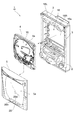
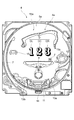
以下、本発明の好適な実施形態について図面を参照しながら説明する。なお、図面の説明において、同一または相当要素には同一の符号を付し、重複する説明は省略する。図1は本発明の第一の実施形態に係るパチンコ遊技機を正面側から示す斜視図、図2は図1に示すパチンコ遊技機の分解斜視図、図3は図1に示すパチンコ遊技機を背面側から示す斜視図、図4は図2に示す遊技盤の正面図、図5は図1に示すパチンコ遊技機の部分断面図である。 Preferred embodiments of the present invention will be described below with reference to the drawings. In the description of the drawings, the same or corresponding elements are denoted by the same reference numerals, and redundant description is omitted. 1 is a perspective view showing a pachinko gaming machine according to a first embodiment of the present invention from the front side, FIG. 2 is an exploded perspective view of the pachinko gaming machine shown in FIG. 1, and FIG. 3 is a perspective view of the pachinko gaming machine shown in FIG. FIG. 4 is a front view of the gaming board shown in FIG. 2, and FIG. 5 is a partial sectional view of the pachinko gaming machine shown in FIG.
(遊技機の構成)
図1に示すパチンコ遊技機1は、遊技場(ホール)の所定の設置枠に収容されて設置される外枠2を備えている。外枠2の正面側には、外枠2に対して回動可能に設けられたベースドア(内枠)3が配設され、ベースドア3内には、図2に示す遊技盤4が組み込まれている。また、外枠2の正面には、フロント扉5が設けられている。フロント扉5は、遊技盤4の正面を覆うとともに、ベースドア3の正面側に回動可能に設置されている。
(Composition of gaming machine)
A
また、パチンコ遊技機1には、プリペイドカードなどが挿入されると、当該プリペイドカードの残高に応じて、遊技球が貸し出されるように構成されたカードユニット84が隣接して併設されている。
Further, the
フロント扉5は、その中央の略全域にガラス板5aを備え、その内側の遊技盤4が視認可能な構成とされている。フロント扉5の下部には、カードユニット84のカード返却操作や遊技球の貸し出し(玉貸し)操作等を行う玉貸し操作関連ボタンを有する玉貸し操作パネル28が設けられている。また、この玉貸し操作パネル28には、所定の操作を行う決定ボタン20aおよび選択ボタン20b,20cが設けられている。
The
また、フロント扉5の下側には、外枠2に対して開閉可能な皿パネル6が設置されている。この皿パネル6の正面側には、カードユニット84により貸し出された遊技球および後述する入賞口に入球した場合に払い出される遊技球を受け止める上皿6aと、この上皿6aの満杯時に球出口6dの内方で溢れた遊技球を受け止める下皿6bと、この下皿6bの右側に設けられた発射ハンドル6cと、が配置されている。
A
発射ハンドル6cは、上皿6aに受け止められている遊技球を発射するためのもので、皿パネル6に対して回動自在に設けられ、遊技者は発射ハンドル6cを操作することによりパチンコ遊技を進めることができる。この発射ハンドル6cが遊技者によって握持され、かつ、時計回り方向へ回動操作されたときに、その回動角度に応じて、発射ハンドル6cの背面側に設けられた発射モータに電力が供給され、遊技球が遊技盤4に順次発射される。
The
発射された遊技球は、図4に示すように、遊技盤4の左側に設けられたガイドレール7により案内され、遊技盤4の上部に移動し、その後、図示しない遊技釘等との衝突によりその進行方向を変えながら遊技盤4の下方に向かって流下する。
As shown in FIG. 4, the launched game ball is guided by a
遊技盤4には、遊技状態において遊技球が流下する領域となる遊技領域4aが形成されており、この遊技領域4a内に、遊技球の流下方向を変更させる多数の遊技釘が設けられている。また、図3に示すように、遊技領域4a上において、遊技盤面を左右に仕切る中心線上であって、高さ方向の中央部には始動入賞口9が設けられている。さらに、その中心線の左側であって高さ方向の中央部には、普通図柄作動ゲート10が設けられている。
The
また、その中心線上であって、高さ方向の下部には、第一大入賞口11が設けられており、その中心線よりも右側であって高さ方向に若干高い位置(肩部)には、第二大入賞口12が設けられている。さらに、始動入賞口9の側方には、一般入賞口13a,13bが設けられている。また、遊技領域4aの中央部下端部には、アウト口14が設けられている。
In addition, a first
始動入賞口9は、遊技球が入賞可能とされている。始動入賞口9には、始動入賞口スイッチ9S(図6)が設けられており、始動入賞口9に遊技球が入賞することにより、始動入賞口スイッチ9Sが遊技球を検出する。始動入賞口スイッチ9Sが遊技球を検出すると、主制御回路30におけるメインCPU31では、大当り判定するための大当り判定用乱数値等の抽出を行う。
In the
この普通図柄作動ゲート10は、遊技球が通過可能とされており、遊技球が通過したことを条件として普通図柄当り判定用乱数値を抽出するトリガーとなる通過ゲートとされている。この普通図柄当り判定用乱数値の抽出により遊技状態が特定遊技状態の一つである普通図柄大当り遊技状態となったときに、始動入賞口9に具備されている1対の羽根(普通電動役物、チューリップ)9aが所定秒数開閉し、入賞がしやすくなる。
The normal
第一大入賞口11は、上述した大当り判定用乱数値の抽出により遊技状態が大当り状態となったときに、閉じているシャッタ(アタッカー)が所定条件の下で開閉する。第一大入賞口11は、このシャッタに遊技球が入球(入賞)すると、所定数の遊技球(例えば15個)が賞球として払出されるトリガーとなる入賞口とされている。
When the gaming state becomes a big hit state by extracting the big hit determination random number described above, the first big winning
第二大入賞口12は、上述した大当り判定乱数値の抽出により遊技状態が大当り遊技状態となったときに、1対の羽根(普通電動役物、チューリップ)12aが所定秒数開閉し、入賞がしやすくなる。第二大入賞口12は、この1対の羽根12aに遊技球が入球(入賞)すると、所定数の遊技球(例えば15個)が賞球として払出されるトリガーとなる入賞口とされている。
In the second
一般入賞口13a,13bは、遊技球が入球(入賞)すると、所定数の遊技球(例えば10個)が賞球として払出されるトリガーとなる入賞口とされている。
The general winning
アウト口14は、始動入賞口9、大入賞口11,12、一般入賞口13a,13bなどの何れにも入球しなかった遊技球を受け入れるものである。
The out
また、遊技盤4は、透光性基板15からなり、この透光性基板15は、たとえばポリカーボネートなどの合成樹脂あるいはその他の透明な部材(透光性部材)で形成された透明部を有している。ここで、「透明な部材」とは、光透過率が100%又はその部材を通して対象を視認可能な程度に光透過率が高いものをいう。本実施形態の遊技領域4aはその大半が透明遊技領域となっている。この透光性基板15には、遊技釘が少なくともその先端部を埋設されて固定され、この透光性基板15とフロント扉5のガラス板5aにより形成された領域が遊技領域4aとされている。そして、この透光性基板15の背面側には、図2および図5に示すように、各種画像情報を表示する大画面の表示領域16aを有する画像表示手段としての液晶表示装置16が配置されている。すなわち、この液晶表示装置16に表示された画像は、透光性基板15の略中央の遊技釘8が設けられていない部分と、その周辺の遊技釘8が設けられている部分を通して、遊技者がパチンコ遊技機1の正面側から視認することができる。
The
この表示領域16aには、図4に示すように、装飾図柄Dおよび本発明の識別図柄である特別図柄Jが表示される。特別図柄Jは、表示領域16aの隅に小さく表示され、遊技者が視認可能ではあるが、視認しにくい位置に表示される。特別図柄Jとしては、「−」、「3」、「7」の3種類の図柄が表示される。これらの特別図柄Jのうち、「3」、「7」が本発明の特定識別図柄である大当り図柄となる。特に、「3」は通常大当り図柄となり、「7」は確変大当り図柄となる。また、「−」ははずれ図柄となる。装飾図柄Dは、複数列(本実施形態においては3列)からなる右装飾図柄DR、中装飾図柄DC、および左装飾図柄DLで構成され、これらはすべて1桁の数字で表されており、その結果、装飾図柄Dは3桁の数字列で表示される。装飾図柄Dは、表示領域16aの中央部に3桁の数字で表示され、遊技者が視認し易い状態で大きく表示される。
In the
装飾図柄Dは、特別図柄Jに対応しており、特別図柄Jが「−」である場合には、3桁の数字列がゾロ目でない数字列(はずれ対応図柄)が停止表示され、特別図柄Jが「3」のときには、偶数の3桁からなるゾロ目の数字列(通常大当り対応図柄)が停止表示され、特別図柄Jが「7」のときには、奇数の3桁からなるゾロ目の数字列(確変大当り対応図柄)の停止表示がなされる。ただし、後に説明する「フリーズ演出」または「はずれ逆転演出」が行われる場合には、大当り遊技状態に移行するまでの間、特別図柄Jが「3」または「7」である場合でも、はずれ対応図柄が表示されることがある。この表示領域16aを有する液晶表示装置16が、本発明の識別図柄表示装置および装飾図柄表示装置となる。また、表示領域16aには、これらの特別図柄および装飾図柄の他にも、背景画像、キャラクタ画像、普通図柄画像等が表示される。
The decorative symbol D corresponds to the special symbol J, and when the special symbol J is “−”, the digit string in which the three-digit numeric character string is not flat is displayed in a stopped manner. When J is "3", the even-numbered three-digit number string (usually big hit symbol) is stopped and displayed. When the special symbol J is "7", the odd-numbered three-digit number The stop display of the column (probability big hit corresponding symbol) is made. However, if the “Freeze effect” or “Outside reverse effect” described later is performed, even if the special symbol J is “3” or “7” until the big hit gaming state is reached A symbol may be displayed. The liquid
また、透光性基板15の下部側の背面側には、図5に示すように、入賞口に入賞した遊技球を入賞球センサに案内する入賞球集合アッセンブリ17等の部材が配設されている。この入賞球集合アッセンブリ17等の部材を遊技者から視認不可能とすべく、透光性基板15の背面にたとえばCAB(セルロースアセトブチレート)から成るセルシートSSを張り、不透明領域としている。
Further, as shown in FIG. 5, members such as a winning
このように、透光性基板15は、その全部を透明部とする必要はなく、光透過率が低い部分や光透過率が0の領域を部分的に有する態様としてもよい。光透過率を低くしたり0にする手段としては、上記背面のセルシートSSの他に、表面に塗装、もしくは物理的蒸着法、化学的蒸着法等を施して模様層、色彩層を形成したり、あるいは、基材となる合成樹脂に染料や顔料を含浸させて、光透過率を低下させたものであってもよい。
Thus, the
液晶表示装置16は、図2に示すように、その表示領域16aに、特別図柄J、装飾図柄(飾り図柄)D、普通図柄、キャラクタ等を可変表示する。特別図柄Jは、大当りか否の判定の結果を示す図柄である。
As shown in FIG. 2, the liquid
また、ここで言う「可変表示」とは、変動可能に表示される概念であり、たとえば、実際に変動して表示される「変動表示」、実際に停止して表示される「停止表示」等を可能とするものである。また、これらの他に、単に特別図柄が出現するように仮に停止表示される「出現表示」、特別図柄ゲームの結果として特別図柄が表示される「導出表示」等を可能とするものである。 In addition, the “variable display” here is a concept that is displayed in a variable manner, for example, “variable display” that is actually changed, “stop display” that is actually stopped, and the like. Is possible. In addition to these, “appearance display” in which a special symbol is simply displayed so that a special symbol appears, “derivation display” in which a special symbol is displayed as a result of a special symbol game, and the like are possible.
さらに、パチンコ遊技機1は、図2に示すように、液晶表示装置16の上方に、所定の遊技状態となったことを遊技者に報知する効果音や音声などを出力するスピーカ18L,18R、図4に示すように、遊技盤4の下部に、所定の遊技状態となったことを所定のパターンで点灯・消灯することによって報知する装飾ランプ19L,19R、上述したカードユニット84により貸し出された遊技球および始動入賞口9、大入賞口11,12、一般入賞口13a,13bにより賞球された遊技球を上皿6aに払い出す払出装置81(図6参照)等を具備している。
Further, as shown in FIG. 2, the
また、パチンコ遊技機1の背面側には、図3に示すように、遊技者に有利な遊技状態(大当り遊技状態)に移行するか否かを判定する主制御回路30を備える主制御基板21、映像および音声等の演出を制御する副制御回路40を備える副制御基板22、遊技球の払出・発射を制御する払出・発射制御回路80を備える払出・発射制御基板23、電源を供給する電源供給ユニット24、電源スイッチ25、バックアップクリアスイッチ26およびモード切換スイッチ27が、それぞれ配置されている。
Further, on the back side of the
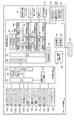
図6は、図1〜図5に示すパチンコ遊技機1の内部の構成を中心に示すブロック構成図である。パチンコ遊技機1は、上述した主制御回路30、副制御回路40、払出・発射制御回路80、電源供給ユニット24を中心に複数の構成要素を有し、この電源供給ユニット24は、主制御回路30、副制御回路40および払出・発射制御回路80にそれぞれ接続され各々への電力供給が可能とされている。主制御回路30は、1チップマイコンより構成されているメインCPU(Central Processing Unit)31、メインROM(Read Only Memory)32およびメインRAM(Random Access Memory)33を有し、他に初期リセット回路34とコマンド出力ポート35を有している。
FIG. 6 is a block configuration diagram illustrating mainly the internal configuration of the
メインCPU31は、後述する第一Vカウントスイッチ11Sなどから遊技球の検出信号を入力する一方、メインROM32に記憶されている制御プログラムにしたがい作動して、パチンコ遊技機1における大当り抽選や、賞球排出といったパチンコ遊技機1全体の動作制御を司り、コマンド出力ポート35を介して副制御回路40に各種のコマンドを送信する。メインCPU31は、大当り抽選の結果や遊技状態の消化などにより、通常遊技状態と通常遊技状態よりも遊技者にとって有利な特定遊技状態である大当り遊技状態との間を移行制御している。ここで、メインCPU31は、本発明の遊技状態移行手段を構成しており、大当り抽選に当選することが、通常遊技状態から特定遊技状態への移行を行う移行条件となる。
The
メインROM32には、メインCPU31が実行する制御プログラムと、恒久的なデータが記憶されている。また、メインROM32には、図7(a)に示す変動パターンテーブルおよび図7(b)に示す特別図柄決定テーブルが記憶されている。メインRAM33はメインCPU31が作動する際に用いるデータやプログラムが一時的に記憶されるようになっている。初期リセット回路34は、リセット信号をメインCPU31に定期的に出力する。このリセット信号により、メインCPU31は制御プログラムの先頭から処理を実行する。
The
また、主制御回路30には、第一Vカウントスイッチ11Sをはじめとする各スイッチ等が接続されている。第一Vカウントスイッチ11Sは第一大入賞口11内に設けられたVゾーンを通過した遊技球の個数を計測し、計測結果を示す検出信号を主制御回路30に出力する。第二Vカウントスイッチ12Sは、第二大入賞口12内に設けられたVゾーンを通過した遊技球の個数を計測し、計測結果を示す検出信号を主制御回路30に出力する。第一カウントスイッチ11CSは第一大入賞口11に入賞した遊技球の個数を計測し、計測結果を示す検出信号を主制御回路30に出力する。第二カウントスイッチ12CSは第二大入賞口12に入賞した遊技球の個数を計測し、計測結果を示す検出信号を主制御回路30に出力する。一般入賞口スイッチ13Sは各一般入賞口13a,13bに入賞した遊技球の検出信号を主制御回路30に出力する。作動ゲートスイッチ10Sは普通図柄作動ゲート10を通過する遊技球の検出信号を主制御回路30に出力する。始動入賞口スイッチ9Sは始動入賞口9に入賞した遊技球の検出信号を主制御回路30に出力する。遊技球が始動入賞口9に入賞し、始動入賞口スイッチ9Sが遊技球を検出することが、本発明の始動条件となる。
The main control circuit 30 is connected to each switch including the first V count switch 11S. The first
始動口ソレノイド9Lは始動入賞口9に設けられた一対の羽根9a,9aを開閉させ、第一大入賞口ソレノイド11Lは第一大入賞口11に設けられたシャッタを開閉させる。また、第二大入賞口ソレノイド12Lは第二大入賞口12に設けられた一対の羽根12a,12aを開閉させ、シーソーソレノイド11Mは第一大入賞口11に設けられた図示しないシーソーを駆動する。バックアップクリアスイッチ26は、電断時等におけるバックアップデータを操作者の操作に応じてクリアする。
The
パチンコ遊技機1では、始動入賞口スイッチ9Sが遊技球の入賞を検出して検出信号を出力したときに主制御回路30から副制御回路40に図柄指定コマンドを出力して、乱数抽出および抽出した乱数を用いた抽選処理を行わせ、その抽選結果に基づき、液晶表示装置16における特別図柄を用いた表示図柄を決定させている。
In the
また、主制御回路30におけるメインCPU31は、大当り抽選によって、はずれ、通常大当り、確変大当りを決定する。通常大当りおよび確変大当りにより、遊技状態は通常遊技状態よりも遊技者にとって有利な特定遊技状態に移行する。このうち、大当りが通常大当りである場合は、特定遊技状態終了後に、通常遊技状態に移行する。また、大当りが確変大当りである場合は、特定遊技状態終了後に、再度特定遊技状態に移行しやすい確変遊技状態に移行する。また、はずれとなった場合には、大入賞装置の開閉制御を行うことはないが、大当りとなった場合には、第一大入賞口11および第二大入賞口12を開閉制御する。
Further, the
副制御回路40は、主制御回路30からコマンドを入力し、その入力したコマンドにしたがい、液晶表示装置16を用いた識別図柄の可変表示、リーチ演出、予告演出といった演出に必要な制御を行う一方、所定の画像を液晶表示装置16に表示させる。また、副制御回路40は、スピーカ18L、18Rを用いた音声出力による演出や装飾ランプ19L、19Rを用いた点滅表示による演出を行うのに必要な制御も行う。
The sub-control circuit 40 inputs a command from the main control circuit 30 and performs control necessary for effects such as variable display of identification symbols, reach effects, and notice effects using the liquid
この副制御回路40は、サブCPU41を中心に構成され、サブROM42と、サブRAM43およびコマンド入力ポート48を有し、画像制御回路50と、音声制御回路60、およびランプ制御回路70を有している。また、副制御回路40には、モード切換スイッチ27が接続されている。
The sub-control circuit 40 is mainly composed of a sub-CPU 41, has a sub-ROM 42, a sub-RAM 43, and a
サブCPU41は、主制御回路30から入力したコマンドにしたがいサブROM42に記憶されているプログラムに沿った処理を実行し、画像制御回路50、音声制御回路60およびランプ制御回路70を作動させる一方、モード切換スイッチ27、選択ボタン20b,20c、決定ボタン20aからの信号にしたがい電源供給ユニット24を制御する。サブROM42にはサブCPU41が実行するプログラムと、恒久的なデータが記憶されている。
The
また、サブCPU41は、本発明の装飾図柄決定手段を構成し、サブROM42は、装飾図柄記憶手段を構成する。サブROM42には、図8(a)に示す表示パターンテーブル、図8(b)に示す当り装飾図柄決定テーブル、図8(c)に示す再変動表示パターン決定テーブル、図9(a)に示す左装飾図柄決定テーブル、図9(b)に示す右装飾図柄決定テーブル、および図9(c)に示す中装飾図柄決定テーブルが記憶されている。
Further, the
このうち、図8(b)に示す装飾図柄決定テーブルには、特別図柄が大当り図柄となった場合に対応する大当り対応図柄が記憶されており、主制御回路30から受信した図柄コマンドz1のときが通常大当り対応図柄であり、z2のときが確変大当り対応図柄である。また、図9(a)〜(c)に示す装飾図柄決定テーブルによって、特別図柄がはずれ図柄となった場合のはずれ対応図柄が生成される。また、サブRAM43はサブCPU41が作動する際に用いるデータやプログラムが記憶されている。
Among these, the decorative symbol determination table shown in FIG. 8B stores a big hit correspondence symbol corresponding to the case where the special symbol is a big hit symbol, and when the symbol command z1 received from the main control circuit 30 is received. Is a symbol corresponding to a normal big hit, and z2 is a symbol corresponding to a probable big hit. In addition, by the decorative symbol determination table shown in FIGS. 9A to 9C, a loss corresponding symbol is generated when the special symbol becomes a loss symbol. The
サブCPU41は、主制御回路30から出力される特別図柄決定テーブルから選択された図柄コマンドに応じた特別図柄を液晶表示装置16に表示させる。たとえば、はずれとなる図柄コマンドz0を受信した場合には、液晶表示装置16に特別図柄Jとして「−」を表示させる。また、通常大当りとなる図柄コマンドz1を受信した場合には、液晶表示装置16に特別図柄Jとして「3」を表示させる。さらに、確変大当りとなる図柄コマンドz2を受信した場合には、液晶表示装置16に特別図柄Jとして「7」を表示させる。
The
また、サブCPU41は、後に示す工程を経て決定される装飾図柄Dを液晶表示装置16に表示させる。したがってサブCPU41は、本発明の識別図柄表示制御手段および装飾図柄表示制御手段として機能する。さらに、サブCPU41は、本発明の条件判断手段および報知演出手段としても機能する。
Further, the
画像制御回路50は、VDP(Video Display Processor)51と、D/Aコンバータ52と、初期リセット回路53と、画像データROM(画像記憶手段)54a,54bとを有している。VDP51は、サブCPU41で決定された液晶表示装置16に表示させる内容に応じた画像を形成し、その形成された画像をD/Aコンバータ52に出力する。D/Aコンバータ52はVDP51から出力される画像データをD/A変換して、変換により得られたアナログ信号を液晶表示装置16に出力し、画像を表示させる。初期リセット回路53はサブCPU41からのリセット命令を受けて、VDP51を初期状態に戻す処理を実行する。画像データROM54aには、装飾図柄、特別図柄、キャラクタ、背景などを示す画像のデータ(画像データ)を記憶し、画像データROM54bには、各種画像データを液晶表示装置16に表示させるための画像データを記憶している。VDP51は、サブCPU41から出力される装飾図柄および特別図柄に対応する画像データを画像データROM54a,54bから読み出し、この画像データに基づく図柄等の画像を液晶表示装置16に表示させる。
The image control circuit 50 includes a VDP (Video Display Processor) 51, a D /
音声制御回路60は、音源IC61と、アンプ(以下「AMP」という)62と、音声データROM63とを有している。音源IC61は、サブCPU41からの指示にしたがい、音声データROM63に記憶されている音声データを用いて音声信号を生成する。AMP62は、音源IC61により生成された音声信号を適切なレベルに増幅し、増幅した音声信号をスピーカ18L、18Rに供給して音声を出力させる。音声データROM63は予告演出、リーチ演出、大当り演出などに用いられる音楽、音声、効果音などのデータ(音声データ)を記憶している。
The audio control circuit 60 includes a sound source IC 61, an amplifier (hereinafter referred to as “AMP”) 62, and an audio data ROM 63. The sound source IC 61 generates an audio signal using audio data stored in the audio data ROM 63 in accordance with an instruction from the
ランプ制御回路70は、装飾ランプ19L、19Rの点滅パターンを示す装飾データを記憶した装飾データROM71と、サブCPU41からの指示にしたがい、装飾データROM71に記憶されている装飾データを用いて装飾ランプ19L、19Rを点滅させるドライブ回路72とを有している。
The lamp control circuit 70 uses the decoration data ROM 71 that stores decoration data indicating the blinking pattern of the
払出・発射制御回路80は、主制御回路30の制御にしたがい払出装置81と、発射ハンドル6cおよび発射モータを有する発射装置82とを作動させて、所定数の遊技球を賞球として払出させるとともに、遊技球を遊技盤4上の遊技領域4aに向けて発射させる。
The payout /
電源供給ユニット24は、副制御回路40の制御にしたがい副制御回路40、主制御回路30および払出・発射制御回路80への電力供給を行うとともに、モード切換スイッチ27のONにより払出・発射制御回路80、主制御回路30への電力供給を制限する。
The power supply unit 24 supplies power to the sub control circuit 40, the main control circuit 30, and the payout /
(パチンコ遊技機の動作内容)
次に、パチンコ遊技機1の動作内容のうち、主制御回路30および副制御回路40による制御処理の手順について、図10〜図18までのフローチャートを参照して説明する。図10はパチンコ遊技機1において、電源を投入したあとに主制御回路30により繰返し実行されるメイン制御処理の動作手順を示すフローチャート(メインフローチャート)である。
(Operation details of pachinko machines)
Next, among the operation contents of the
(メイン制御処理の動作手順)
図10に示すように、パチンコ遊技機1は、電源投入に伴い主制御回路30のメインCPU31がメイン制御処理を開始し、初期設定処理を行い(S1)、次に、特別図柄制御処理(S2)を行う。この特別図柄制御処理については、後に説明する。その後、普通図柄制御処理を行い(S3)、続いて乱数更新処理を行う(S4)。以後、このステップS2〜ステップS4の工程を順次実行する繰返ルーチンに進む。
(Operation procedure of main control processing)
As shown in FIG. 10, in the
特別図柄制御処理は、図11に示すフローチャートのようにして行われる。特別図柄制御処理を開始すると、まず、制御状態フラグをロードする(S11)。この制御状態フラグは、液晶表示装置16における図柄の可変表示画像を用いた特別図柄ゲームの状態を示すフラグであって、メインCPU31が後続の各ステップS72〜S80までのいずれを実行するかを判定するためのデータが設定されている。
The special symbol control process is performed as shown in the flowchart of FIG. When the special symbol control process is started, first, a control state flag is loaded (S11). This control state flag is a flag indicating the state of the special symbol game using the symbol variable display image in the liquid
次に、特別図柄記憶チェック処理(S12)が図12に示すフローチャートの手順に沿って行われる。この特別図柄記憶チェック処理を開始すると、メインCPU31は、制御状態フラグが特別図柄記憶チェックを示すデータ“00”か否かを判断する(S21)。その結果、 “00”でなければ処理を終了する。また、“00”である場合には、保留個数が“0”か否かを判定する(S22)。その結果、保留個数が“0”であればデモ表示処理を行い(S23)、その後、処理を終了する。一方、保留個数が“0”でなければ、制御状態フラグに特別図柄変動時間管理を示すデータ“01”をセットする(S24)。
Next, a special symbol memory check process (S12) is performed according to the procedure of the flowchart shown in FIG. When the special symbol memory check process is started, the
制御状態フラグに特別図柄変動時間管理を示すデータ“01”をセットしたら、大当り判定用前処理を行う(S25)。このとき、メインCPU31は高確率フラグを読み出して大当り判定テーブルを選択し、大当り判定用乱数を用いて選択された大当り判定テーブルをサーチする。
When data “01” indicating special symbol variation time management is set in the control state flag, pre-processing for jackpot determination is performed (S25). At this time, the
それから、大当り判定用前処理において大当り判定テーブルをサーチした結果に基づいて、大当りであるか否かの判断を行う(S26)。その結果、大当りである場合には、大当り処理を行い(S27)、大当りでなければはずれ処理を行う(S28)。 Then, based on the result of searching the jackpot determination table in the jackpot determination pre-processing, it is determined whether or not it is a jackpot (S26). As a result, if it is a big hit, a big hit process is performed (S27), and if it is not a big hit, a loss process is performed (S28).
大当りの図柄決定処理では、遊技球が始動入賞口9に入賞するときに抽出される大当り用図柄乱数値から確変大当りか通常大当りかを判断し、通常大当りである場合には、図7(b)に示す特別図柄決定テーブルから特別図柄として「3」を選択するとともに図柄コマンドz1を選択して、副制御回路40に出力する。一方、確変大当りである場合には、特別図柄として「7」を選択するとともに図柄コマンドz2を選択して、副制御回路40に出力する。さらに、主制御回路30は遊技状態が特定遊技状態となる遊技状態コマンドを副制御回路40に出力する。
In the jackpot symbol determination process, it is determined whether the game game ball wins the
また、はずれ図柄の決定処理では、図7(b)に示す特別図柄決定テーブルから特別図柄として「−」を選択するとともに図柄コマンドz0を選択して、副制御回路40に出力する。さらに、主制御回路30は遊技状態が通常遊技状態となる遊技状態コマンドを副制御回路40に出力する。
Further, in the off symbol determination process, “−” is selected as the special symbol from the special symbol determination table shown in FIG. 7B and the
その後、メインCPU31は変動パターンの決定を行う(S29)。変動パターンの決定では、図7(a)に示す変動パターンテーブルにおける複数の乱数値のうちから1つを取得し、取得した乱数値に対応する変動パターンコマンドを決定して、決定した変動パターンコマンドを副制御回路40に出力する。変動パターンコマンドとしては、大当り判定処理の結果が大当りである場合にはh4からh8の中から1つが選択され、大当り判定処理の結果がはずれである場合には、h0〜h3の中から1つが選択される。その後、変動パターンテーブルで決定された変動パターンコマンドに対応する変動時間を待ち時間タイマにセットして処理を終了する。
Thereafter, the
図11に示すフローに戻り、特別図柄記憶チェック処理が済んだら、特別図柄変動時間管理処理を行う(S13)。特別図柄変動時間管理処理は、制御状態フラグが特別図柄変動時間管理を示すデータ“01”のときに以下の処理を行い、“01”でなければ行わないようになっている。すなわち、メインCPU31は待ち時間タイマが0でないときに、制御状態フラグに特別図柄表示時間管理を示すデータ“02”をセットし、確定後待ち時間(例えば1秒)を待ち時間タイマにセットする。
Returning to the flow shown in FIG. 11, after the special symbol storage check process is completed, the special symbol variation time management process is performed (S13). The special symbol variation time management process is performed when the control state flag is data “01” indicating the special symbol variation time management, and is not performed unless it is “01”. That is, when the waiting time timer is not 0, the
続いて、特別図柄表示時間管理処理を行う(S14)。特別図柄表示時間管理処理は、制御状態フラグが特別図柄表示時間管理を示すデータ“02”のときに以下の処理を行い、“02”でなければ行わないようになっている。すなわち、メインCPU31は待ち時間タイマが0でなく、大当りのときには制御状態フラグに大当り開始インターバル管理を示すデータ“03”をセットした上で、大当り開始インターバルに対応する時間(例えば10秒、以下「大当り開始対応時間」という)を待ち時間をセットし、大当りでないときは制御状態フラグに特別図柄ゲーム終了を示す値“03”をセットして処理を終了する。
Subsequently, a special symbol display time management process is performed (S14). The special symbol display time management process is performed when the control state flag is data “02” indicating special symbol display time management, and is not performed unless it is “02”. That is, the
さらに、大当り開始インターバル管理処理を行う(S15)。大当り開始インターバル管理処理では、制御状態フラグが大当り開始インターバル管理を示すデータ“03”であるときは、ステップS13でセットされた大当り開始対応時間だけ待機し、大当り開始対応時間が経過したのち、大入賞口の開放させるため、メインROM32から読み出されたデータに基づいてメインRAM33に位置づけられた変数を更新する。さらに、メインCPU31は大入賞口開放中を示すデータ“04”を制御状態フラグにセットし、開放上限時間(例えば30秒)を大入賞口時間タイマにセットする。
Further, a big hit start interval management process is performed (S15). In the big hit start interval management process, when the control state flag is data “03” indicating the big hit start interval management, the big hit start corresponding time set in step S13 is waited. In order to open the winning opening, the variables positioned in the
続いて、大入賞口再開放前待ち時間管理処理を行う(S16)。大入賞口再開放前待ち時間管理処理では、制御状態フラグが大入賞口再開放前待ち時間管理を示すデータ“06”であるときは、ラウンド間インターバルに対応する時間だけ待機する。メインCPU31はラウンド間インターバルに対応する時間を経過した場合に、大入賞口開放回数カウンタを“1”加算して更新し、大入賞口開放中を示すデータ“04”を制御状態フラグにセットし、開放上限時間(例えば30秒)を大入賞口時間タイマにセットする。
Subsequently, a waiting time management process before reopening the big winning opening is performed (S16). In the waiting time management process before reopening the big winning opening, when the control state flag is data “06” indicating the waiting time management before reopening the big winning opening, the process waits for the time corresponding to the interval between rounds. When the time corresponding to the interval between rounds has elapsed, the
さらに、大入賞口開放中処理を行う(S17)。大入賞口開放中処理では、制御状態フラグが大入賞口開放中を示すデータ“04”であるときに以下の処理を行い、“04”でなければ行わないようになっている。すなわち、メインCPU31は、大入賞口入賞カウンタが10以上であるか、開放上限時間を経過した(大入賞口時間タイマが“0”)のいずれかを満たすときに、大入賞口を閉鎖させるためメインRAM33に位置づけられた変数を更新する。また、メインCPU31は制御状態フラグが大入賞口内残留球監視を示すデータ“05”をセットして、大入賞口内残留球監視時間(例えば1秒)を待ち時間タイマにセットし、大入賞口内残留球監視時間を経過したのち、次のステップに進むように設定する。いずれかも満たしたと判定されないときは、上述の処理を実行することなく次のステップに進む。
Furthermore, a special winning opening opening process is performed (S17). In the special prize opening opening process, the following process is performed when the control status flag is data “04” indicating that the special prize opening is open, and if it is not “04”, it is not performed. That is, the
続いて、大入賞口内残留球監視処理を行う(S18)。大入賞口内残留球監視処理では制御状態フラグが大入賞口内残留球監視を示すデータ“05”であるときに以下の処理を行い、“05”でなければ行わないようになっている。メインCPU31は、大入賞口内残留球監視時間が経過したときに、大入賞口における特定領域を遊技球が通過しなかったこと、または大入賞口開放回数カウンタが15以上であるか(最終ラウンドか)否かの条件のいずれかを満たしたかどうかを判定し、いずれかを満たしているときは大当り終了インターバルを示すデータ“07”を制御状態フラグにセットして大当り終了インターバルに対応する時間(以下「大当り終了対応時間」という)を待ち時間タイマにセットする。これにより、大当り終了対応時間を経過したのち、大当りインターバル処理を実行するように設定する。いすれも満たされない場合は大入賞口再開放待ち時間管理を示すデータ“06”を制御状態フラグにセットする。また、ラウンド間インターバルに対応する時間を待ち時間タイマにセットし、その待ち時間を経過したのち、ステップS16における大入賞口再開放前待ち時間管理処理を実行するように設定する。
Subsequently, a special winning opening residual ball monitoring process is performed (S18). In the special winning opening residual ball monitoring process, the following processing is performed when the control state flag is data “05” indicating the special winning opening residual ball monitoring. The
それから、大当り終了インターバル処理を行う(S19)。大当り終了インターバル処理では制御状態フラグが大当り終了インターバルを示すデータ“07”であるときに以下の処理を行い、“07”でなければ行われないようになっている。メインCPU31は、大当り終了インターバルに対応する時間だけ待機して、特別図柄ゲーム終了を示すデータ“08”を制御状態フラグにセットする。メインCPU31は所定の確率変動条件を満たした場合(大当り図柄が確変大当り図柄になったとき)に、大当り確率を変動させるため、高確率フラグに所定のデータをセットする。
Then, a jackpot end interval process is performed (S19). In the big hit end interval processing, the following processing is performed when the control state flag is data “07” indicating the big hit end interval, and if it is not “07”, the processing is not performed. The
そして、特別図柄ゲーム終了処理を行う(S20)。制御状態フラグが特別図柄ゲーム終了処理を示すデータ“08”であるときに以下の処理を行い、“08”でなければ行わないようになっている。メインCPU31は、保留個数を示すデータを“1”減らすように更新し、大当り判定用乱数カウンタ、大当り停止態様選択用乱数カウンタの各カウント値を順次シフトさせる。ステップS80が終了すると、ステップS2の特別図柄制御処理が終了する。
Then, a special symbol game end process is performed (S20). The following processing is performed when the control state flag is data “08” indicating the special symbol game end processing, and if it is not “08”, the processing is not performed. The
こうして特別図柄制御処理が終了すると、図10に戻り、普通図柄制御処理を行う(S3)。普通図柄制御処理では、液晶表示装置16に表示される普通図柄に関する制御を行う。普通図柄制御処理を開始すると、普通図柄制御状態フラグを読出し、そのフラグに応じて普通図柄の変動時間、停止表示された普通図柄の態様を監視する。そして、その普通図柄の態様が所定の態様であるときは普通電動役物の開放、閉鎖を示す変数をメインRAM33に記憶して、普通図柄制御処理が終了する。
When the special symbol control process is thus completed, the process returns to FIG. 10 and the normal symbol control process is performed (S3). In the normal symbol control process, control related to the normal symbol displayed on the liquid
その後、乱数更新処理を行う(S4)。ここでは、はずれ図柄用乱数値、リーチ判定用乱数値、演出条件選択用乱数値などを所定の演算方法により更新する乱数更新処理を行って処理を終了する。そして、ステップS2に戻り繰返しルーチンが繰り返し行われる。 Thereafter, random number update processing is performed (S4). Here, random number update processing for updating the random symbol value for losing symbols, random value for reach determination, random number value for effect condition selection, and the like by a predetermined calculation method is performed, and the processing is terminated. Then, the process returns to step S2 and the repeat routine is repeated.
(副制御回路の動作手順)
次に、副制御回路40の動作について説明する。副制御回路40では、主制御回路30から送信されたコマンドを受信することにより、図柄制御、音制御、およびランプ制御等を行う。図13は、副制御回路40により繰返し実行されるサブ制御処理の手順を示すフローチャートである。
(Sub-control circuit operation procedure)
Next, the operation of the sub control circuit 40 will be described. The sub control circuit 40 performs a symbol control, a sound control, a lamp control, and the like by receiving a command transmitted from the main control circuit 30. FIG. 13 is a flowchart showing a procedure of sub control processing repeatedly executed by the sub control circuit 40.
図13に示すように、サブCPU41では、最初に所定の初期化処理を行い(S31)、次に乱数更新処理を行う(S32)。続いて、主制御回路30から出力されるコマンド解析制御処理を行い(S33)、このコマンド解析制御処理の結果に基づいて表示制御処理を行う(S34)。コマンド解析制御処理については、後に詳しく説明する。
As shown in FIG. 13, the
その後、音制御処理(S35)を行う。音制御処理では、主制御回路30からのコマンドに基づいてスピーカ18L,18Rから発生させる音声に関する音声制御処理を行う。この音声制御処理では、音源IC61は、音声データROM63から音声データを読み出し、音声データを所定の音声信号に変換して、その音声信号をAMP62に供給する。このAMP62は、音声信号を増幅して、スピーカ18L,18Rから音声を発生させる。
Thereafter, a sound control process (S35) is performed. In the sound control process, a sound control process related to the sound generated from the
続いて、ランプ制御処理行う(S36)。ランプ制御処理では、主制御回路30からのコマンドに基づいて装飾ランプ19L,19Rの点滅に関するランプ制御処理を実行する。このランプ制御処理では、サブCPU41は、装飾データROM71からランプ装飾パターンを読み出し、ドライブ回路72を介して、装飾ランプ19L,19Rを点滅させる。以降ステップS32〜ステップS36を繰り返し実行する。
Subsequently, a lamp control process is performed (S36). In the lamp control process, a lamp control process related to blinking of the
次に、主制御回路30から送信されたコマンドを受信した際の処理について説明する。図14に示すように、副制御回路40から主制御回路30から送信されたコマンドを受信したら、まず保護レジスタを退避する(S41)。次に、入力されたコマンドをサブRAM43における受信バッファに格納する(S42)。続いて、レジスタを復帰させる(S43)。こうしてコマンドを受信した際の処理は終了する。 Next, processing when a command transmitted from the main control circuit 30 is received will be described. As shown in FIG. 14, when a command transmitted from the main control circuit 30 is received from the sub control circuit 40, the protection register is first saved (S41). Next, the input command is stored in the reception buffer in the sub RAM 43 (S42). Subsequently, the register is restored (S43). Thus, the process upon receiving the command ends.
続いて、図13のステップS33に示すコマンド解析制御処理について説明する。図15は、コマンド解析制御処理の手順を示すフローチャートである。図15に示すように、コマンド解析制御処理では、まず副制御回路40が主制御回路30から変動パターンコマンドを受信したか否かを判断する(S51)。その結果、変動パターンコマンドを受信していれば、表示パターンの決定処理を行う(S52)。表示パターンの決定処理については、後に説明する。そして、表示パターンの決定処理を行った後、コマンド解析制処理を終了する。 Next, the command analysis control process shown in step S33 of FIG. 13 will be described. FIG. 15 is a flowchart illustrating a procedure of command analysis control processing. As shown in FIG. 15, in the command analysis control process, first, the sub-control circuit 40 determines whether or not a variation pattern command has been received from the main control circuit 30 (S51). As a result, if a variation pattern command has been received, display pattern determination processing is performed (S52). The display pattern determination process will be described later. Then, after the display pattern determination process is performed, the command analysis control process is terminated.
一方、変動パターンコマンドを受信していないと判断した場合には、図柄コマンドを受信しているか否かを判断する(S53)。その結果、図柄コマンドを受信していると判断した場合には、装飾図柄の決定処理を行う(S54)。装飾図柄の決定処理については、後に説明する。そして、装飾図柄の決定処理を行った後、コマンド解析制処理を終了する。一方、図柄コマンドを受信していないと判断した場合には、図柄確定コマンドを受信しているか否かを判断する(S55)。その結果、図柄確定コマンドを受信していると判断した場合には、図柄確定処理を行う(S56)。そして、図柄確定処理を行った後、コマンド解析制処理を終了する。一方、図柄確定コマンドを受信していないと判断した場合には、大当り遊技状態コマンドを受信しているか否かを判断する(S57)。 On the other hand, if it is determined that a variation pattern command has not been received, it is determined whether a symbol command has been received (S53). As a result, if it is determined that the symbol command has been received, a decorative symbol determination process is performed (S54). The decoration symbol determination process will be described later. Then, after performing the decorative symbol determination process, the command analysis control process is terminated. On the other hand, if it is determined that the symbol command has not been received, it is determined whether a symbol confirmation command has been received (S55). As a result, if it is determined that the symbol confirmation command has been received, symbol determination processing is performed (S56). Then, after performing the symbol determination process, the command analysis control process is terminated. On the other hand, if it is determined that the symbol confirmation command has not been received, it is determined whether or not a jackpot gaming state command has been received (S57).
その結果、大当り遊技状態コマンドを受信していると判断した場合には、本発明の差換変動表示である大当り中再変動処理を行い(S58)、遊技状態コマンドに対応するデータをセットする(S59)。大当り中再変動については、後に説明する。一方、大当り遊技状態コマンドを受信していないと判断した場合には、受信したコマンドに対応する処理を実行した後(S60)、コマンド解析制御処理を終了する。 As a result, if it is determined that the big hit gaming state command is received, the big change during the big hit which is the replacement fluctuation display of the present invention is performed (S58), and the data corresponding to the gaming state command is set (S58). S59). The re-variation during jackpot will be explained later. On the other hand, if it is determined that the jackpot gaming state command has not been received, the process corresponding to the received command is executed (S60), and the command analysis control process is terminated.
続いて表示パターンの決定処理について説明する。図16は、表示パターンの決定処理の手順を示すフローチャートである。図16に示すように、表示パターン決定処理においては、受信した変動パターンコマンドが大当りに対応する変動パターンコマンド(h4〜h8)であるか否かを判断する(S61)。その結果、受信した変動パターンコマンドがh0〜h3のいずれかであり、大当りに対応する変動パターンコマンドでないと判断した場合にははずれの表示パターン決定処理を行う(S62)。はずれの表示パターン決定処理では、0〜9のうちの1つの乱数値を取得し、図8(a)に示す表示パターンテーブルに、出力されたコマンド番号と取得した乱数値とを参照して表示パターンおよび表示内容を決定する。 Next, display pattern determination processing will be described. FIG. 16 is a flowchart illustrating a procedure of display pattern determination processing. As shown in FIG. 16, in the display pattern determination process, it is determined whether or not the received variation pattern command is a variation pattern command (h4 to h8) corresponding to the jackpot (S61). As a result, if it is determined that the received variation pattern command is one of h0 to h3 and is not the variation pattern command corresponding to the big hit, the display pattern determination process for losing is performed (S62). In the display pattern determination process for out-of-range, one random number value from 0 to 9 is acquired and displayed in the display pattern table shown in FIG. 8A with reference to the output command number and the acquired random number value. Determine the pattern and display contents.
一方、変動パターンコマンドがh4〜h8のいずれかであり、大当りに対応するものであると判断した場合には、フリーズ演出を行うか否かを決めるのフリーズ演出決定処理を行う(S63)。フリーズ演出の決定処理においては、フリーズ演出決定用乱数値を利用する。ここでは、所定の乱数範囲が予め設定されており、この乱数範囲から一の乱数値を取得する。この取得された乱数値がフリーズ演出を行うとして決められた乱数値である場合にはフリーズ演出を行い、決められた乱数値ではない場合には、フリーズ演出を行わない。 On the other hand, if it is determined that the variation pattern command is any one of h4 to h8 and corresponds to the big hit, freeze effect determination processing for determining whether or not to perform the freeze effect is performed (S63). In the determination process of the freeze effect, a random value for determining the freeze effect is used. Here, a predetermined random number range is set in advance, and one random number value is acquired from this random number range. When the acquired random number value is a random value determined to perform the freeze effect, the freeze effect is performed, and when it is not the determined random value, the freeze effect is not performed.
こうして、フリーズ演出決定処理を行ったら、フリーズ演出を行うか否かを判断する(S64)。その結果、フリーズ演出を行わないと判断した場合には、大当りの表示パターンの決定処理を行う(S65)。大当りの表示パターン決定処理では、0〜9のうちの1つの乱数値を取得し、図8(a)に示す表示パターンテーブルに、出力されたコマンド番号と取得した乱数値とを参照して表示パターンおよび表示内容を決定する。 When the freeze effect determination process is thus performed, it is determined whether or not the freeze effect is performed (S64). As a result, when it is determined that the freeze effect is not performed, the big hit display pattern determination process is performed (S65). In the jackpot display pattern determination process, one random number value from 0 to 9 is acquired and displayed in the display pattern table shown in FIG. 8A with reference to the output command number and the acquired random number value. Determine the pattern and display contents.
一方、フリーズ演出を行うと判断した場合には、フリーズ演出の表示パターン決定処理を行う(S66)。フリーズ演出の表示パターン決定処理では、特別図柄が変動を開始する前において、停止表示されている装飾図柄を、特別図柄の変動表示が開始された後、特別図柄を変動表示させている間、そのまま停止表示させておく。 On the other hand, when it is determined that a freeze effect is to be performed, a display pattern determination process for the freeze effect is performed (S66). In the display pattern determination process of freeze effect, before the special symbol starts to change, the decorative symbol that is stopped is displayed as it is while the special symbol is variably displayed after the special symbol change display is started. Stop display.
装飾図柄の変動表示を始める前には、液晶表示装置16には、図4に示すように、変動表示を始める前の3桁の数字が表示された状態にある。フリーズ演出以外の演出では、特別図柄が変動表示されると、装飾図柄も変動表示され特別図柄が停止表示されるまでの間、装飾図柄の変動表示も継続する。これに対して、フリーズ演出の表示パターンが決定されると、特別図柄の変動表示が行われても、装飾図柄の変動表示を行わないようにする。
Before starting the variable display of the decorative symbols, the liquid
こうして、各表示パターンのいずれかを決定したら、決定した表示パターンに対応する表示パターンデータをセットする(S67)。このようにして表示パターンの決定処理が終了する。 When any one of the display patterns is determined in this way, display pattern data corresponding to the determined display pattern is set (S67). In this way, the display pattern determination process ends.
続いて、図15に示すフローチャートのステップS54における装飾図柄の決定処理について図17を参照して説明する。図17は、装飾図柄決定処理の手順を示すフローチャートである。 Next, the decorative symbol determination process in step S54 of the flowchart shown in FIG. 15 will be described with reference to FIG. FIG. 17 is a flowchart showing the procedure of the decorative symbol determination process.
図17に示すように、装飾図柄決定処理においては、まず、大当りの図柄コマンドを受信したか否かを判断する(S71)。その結果、受信した図柄コマンドがz0であり、大当りの図柄コマンドを受信していないと判断した場合には、はずれ用装飾図柄決定処理を行う(S72)。はずれ用装飾図柄決定処理では、図9に示す装飾図柄決定用テーブルから、左右中のそれぞれの数字を選択し、液晶表示装置16に表示させる図柄を左右中のそれぞれについて決める。ここで、左右中のすべての数字が同一であるか否かを判断して、同一でない場合には、選択された数字で決定され、同一であると判断した場合には、再度左右中のすべての数字を選択しなおして、同一とならなくなるまで繰り返し、同一とならなかった数字で決定される。
As shown in FIG. 17, in the decorative symbol determination process, first, it is determined whether or not a jackpot symbol command has been received (S71). As a result, when it is determined that the received symbol command is z0 and no jackpot symbol command has been received, a decorative symbol determination process for detachment is performed (S72). In the decorative symbol determination process for detachment, the left and right numbers are selected from the decorative symbol determination table shown in FIG. 9, and the symbols to be displayed on the liquid
一方、大当りの図柄コマンドを受信したと判断した場合には、出力された変動パターンコマンドがh8であるか否かを判断する(S73)。その結果、出力された変動パターンコマンドがh8である場合には、本発明の特殊表示条件としてのはずれ逆転演出が行われるため、はずれ用装飾図柄決定処理が行われる(S72)。はずれ逆転演出とは、装飾図柄としてはずれ図柄を表示しておきながら、大当りとなる演出である。ここでのはずれ用装飾図柄決定処理は、大当りの図柄コマンドを受信していない場合と同様にして行われる。はずれ逆転演出については、後に説明する。 On the other hand, if it is determined that the jackpot symbol command has been received, it is determined whether or not the output variation pattern command is h8 (S73). As a result, when the output variation pattern command is h8, the off-set reverse effect is performed as the special display condition of the present invention, and the off-set decorative symbol determination process is performed (S72). The off-line reverse effect is an effect that is a big hit while displaying the off-line symbol as a decorative symbol. Here, the decorative symbol determination process for detachment is performed in the same manner as when the jackpot symbol command is not received. The loss reversal effect will be described later.
また、変動パターンコマンドがh4〜h7であり、h8ではないと判断した場合には、大当り用装飾図柄決定処理を行う(S74)。大当り用装飾図柄決定処理では、主制御回路30から出力された図柄コマンドがz1であるかz2であるかを判断し、図柄コマンドがz1である場合には通常大当りであり、図8(b)に示す乱数値を取得して、その乱数値に対応する装飾図柄、具体的には、3桁の偶数をゾロ目表示した装飾図柄を装飾図柄決定テーブルから選択して、装飾図柄を決定する。また、図柄コマンドがz2である場合には確変大当りであり、図8(b)に示す乱数値を取得して、その乱数値に対応する装飾図柄、具体的には、3桁の奇数をゾロ目表示した装飾図柄を装飾図柄決定テーブルして、装飾図柄を決定する。 On the other hand, if it is determined that the variation pattern command is h4 to h7 and not h8, a big hit decoration symbol determination process is performed (S74). In the big hit decorative symbol determination process, it is determined whether the symbol command output from the main control circuit 30 is z1 or z2, and when the symbol command is z1, it is usually a big hit, and FIG. Is selected from the decorative design determination table, and a decorative design corresponding to the random value is selected from the decorative design determination table to determine the decorative design. Further, when the symbol command is z2, it is a probable big hit, the random value shown in FIG. 8B is acquired, and a decorative symbol corresponding to the random value, specifically, a three-digit odd number is zeroed. The decorative design determined table is used to determine the decorative design.
このようにして、はずれ用装飾図柄決定処理または大当り用装飾図柄決定処理を行ったら、決定した装飾図柄に対応するデータをセットする(S75)。このようにして、装飾図柄決定処理が終了する。 In this way, when the off-set decorative symbol determination process or the big hit decorative symbol determination process is performed, data corresponding to the determined decorative symbol is set (S75). In this way, the decorative symbol determination process ends.
図15に示すフローチャートのステップS58の大当り中再変動処理について説明する。図18は、大当り中再変動処理の手順を示すフローチャートである。図18に示すように、大当り中再変動処理では、まず、遊技状態コマンドとして、大当り遊技状態コマンドを受信しているか否かを判断する(S81)。その結果、大当り遊技状態コマンドを受信していないと判断した場合には、大当り中再変動処理を終了する。また、大当り遊技状態コマンドを受信していると判断した場合には、ステップS52における表示パターン決定処理(図16)でフリーズ演出が決定されているか否かを判断する(S82)。その結果、フリーズ演出が決定されていない場合には、はずれ逆転演出が決定されているか否かを判断する(S83)。はずれ逆転演出が決定されているか否かの判断は、主制御回路30から出力された変動パターンコマンドがh8であるか否かによって行われる。その結果、変動パターンコマンドがh4〜h7でありはずれ逆転演出が決定されていない場合、大当り用装飾図柄決定処理が行われているので、液晶表示装置には、3桁のゾロ目の数字が表示されており、装飾図柄として、大当りを示す装飾図柄が表示される。したがって、はずれ逆転演出が決定されていない場合には、処理を終了する。 The big hit re-variation process in step S58 of the flowchart shown in FIG. 15 will be described. FIG. 18 is a flowchart showing the procedure of the re-variation process during the big hit. As shown in FIG. 18, in the big hit re-variation process, first, it is determined whether or not a big hit gaming state command is received as a gaming state command (S81). As a result, when it is determined that the jackpot gaming state command has not been received, the re-variation process during the jackpot is terminated. If it is determined that the jackpot gaming state command is received, it is determined whether or not the freeze effect is determined in the display pattern determination process (FIG. 16) in step S52 (S82). As a result, when the freeze effect is not determined, it is determined whether or not the reverse rotation effect is determined (S83). The determination as to whether or not the reverse rotation effect has been determined is made based on whether or not the variation pattern command output from the main control circuit 30 is h8. As a result, when the variation pattern command is h4 to h7 and the reverse rotation effect is not determined, the big-decoration decorative symbol determination processing is performed, so the liquid crystal display device displays a three-digit number of the second digit. As a decorative pattern, a decorative pattern indicating a big hit is displayed. Therefore, when the outlier reverse effect is not determined, the process is terminated.
また、ステップS82またはステップS83でフリーズ演出またははずれ逆転演出がされると判断した場合には、大当り用装飾図柄決定処理を行う(S84)。フリーズ演出またははずれ逆転演出が決定されている場合には、ほとんどの場合、大当り遊技中、大当り遊技状態に対応する3桁の数字がゾロ目表示された状態とはなっていない。したがって、改めて大当り用装飾図柄決定処理を行って、大当り用装飾図柄を表示制御する。大当り用装飾図柄決定処理は、上述の場合と同様にして行うことができる。 On the other hand, if it is determined in step S82 or step S83 that a freeze effect or a reverse rotation effect is to be performed, a big hit decorative symbol determination process is performed (S84). When the freeze effect or the reverse rotation effect is determined, in most cases, the three-digit number corresponding to the big hit game state is not in a state where the double win game is displayed. Therefore, the big hit decorative symbol determination process is performed again to control the display of the big hit decorative symbol. The big hit decoration design determination process can be performed in the same manner as described above.
大当り用装飾図柄決定処理が済んだら、再変動パターン決定処理を行う(S85)。再変動パターン決定処理では、図8(c)に示す再変動表示パターンテーブルにおける複数の乱数値(0〜9)のうちの一つを取得し、取得した乱数値に対応する表示内容を再変動パターンとして決定する。 After the big hit decoration design determination process is completed, a re-variation pattern determination process is performed (S85). In the re-variation pattern determination process, one of a plurality of random values (0 to 9) in the re-variation display pattern table shown in FIG. 8C is acquired, and the display content corresponding to the acquired random value is re-variable. Determine as a pattern.
その後、装飾図柄に対応する大当り用装飾図柄の図柄データをセットし(S86)、さらに、決定した再変動パターンに対応するデータをセットし(S87)、大当り再変動処理を終了する。 Thereafter, the symbol data for the big hit decorative symbol corresponding to the decorative symbol is set (S86), further the data corresponding to the determined re-variation pattern is set (S87), and the big hit re-variation processing is terminated.
続いて、フリーズ演出、大当り中再変動、およびはずれ逆転演出について説明するが、その前に通常の特別図柄ゲームの流れについて説明する。特別図柄ゲームでは、始動入賞口9に遊技球が入賞し、始動入賞口スイッチ9Sが遊技球の検出信号を主制御回路30に出力すると、主制御回路30では大当り抽選を行う。主制御回路30は、その抽選結果から図7(a)に示す変動パターンテーブルからコマンド番号および図7(b)に示す特別図柄決定テーブルから図柄コマンドを選択し、それぞれ副制御回路40に送信する。
Next, the freeze effect, the big change during the big hit, and the reverse rotation effect will be described. Before that, the flow of the normal special symbol game will be described. In the special symbol game, when the game ball wins the
副制御回路40では、変動パターンのコマンド番号および図柄コマンドを受信し、図8(a)に示す表示パターンテーブルから表示パターンを選択するとともに、図8(b)または図9に示す各テーブルから装飾図柄を選択する。 The sub control circuit 40 receives the command number and symbol command of the variation pattern, selects a display pattern from the display pattern table shown in FIG. 8A, and decorates from each table shown in FIG. 8B or FIG. Select a design.
表示領域16aにおいては、始動入賞口9に遊技球が入賞する前は、図19(a)に示すように、装飾図柄DL,DR,DCおよび特別図柄Jは、いずれも停止表示されている。この状態から、始動入賞口9に遊技球が入賞すると、図19(b)に示すように、装飾図柄DL,DR,DCおよび特別図柄Jが変動表示を開始する。
In the
それから、図19(c)に示すように、左装飾図柄DLが停止表示される。このときには、中装飾図柄DC、右装飾図柄DR、および特別図柄Jは変動表示している。その後、右装飾図柄DRが停止表示され、続いて中装飾図柄DCおよび特別図柄Jが停止表示される。ここで、主制御回路30における大当り抽選の結果がはずれである場合には、図19(d)に示すように、左右中装飾図柄DL,DR,DCで異なる数字、この例では、「512」が表示される。これらの数字は、副制御回路40における図9(a)〜(c)に示す各装飾図柄決定テーブルから選択された数字である。また、特別図柄Jとしては「−」の記号が表示される。 Then, as shown in FIG. 19C, the left decorative symbol DL is stopped and displayed. At this time, the middle decorative symbol DC, the right decorative symbol DR, and the special symbol J are variably displayed. Thereafter, the right decorative symbol DR is stopped and displayed, and then the middle decorative symbol DC and the special symbol J are stopped and displayed. Here, when the result of the big hit lottery in the main control circuit 30 is out of place, as shown in FIG. 19 (d), different numbers are used for the left and right decorative symbols DL, DR, DC, in this example, “512”. Is displayed. These numbers are numbers selected from the decorative design determination tables shown in FIGS. 9A to 9C in the sub control circuit 40. In addition, the symbol “-” is displayed as the special symbol J.
一方、大当り抽選での結果が大当りである場合には、図19(e)に示すように、左右中装飾図柄DL,DR,DCに同一の数字、この例では「555」が表示される。また、特別図柄Jとしては、「7」が表示される。その後、大当りが確変大当りである場合には、図4に示す第一大入賞口11が開放制御される。また、大当りが通常大当りである場合には、第二大入賞口12が開放制御される。
On the other hand, when the result of the big hit lottery is a big hit, as shown in FIG. 19 (e), the same number, “555” in this example, is displayed on the left and right middle decorative symbols DL, DR, and DC. As the special symbol J, “7” is displayed. Thereafter, when the big hit is a probable big hit, the first big winning
それでは、次に、フリーズ演出について説明する。主制御回路30の大当り抽選の結果が大当りであり、副制御回路40のサブCPU41における制御ルーチンの図16のステップS63でフリーズ演出を行うと判断された場合には、表示領域16aには、次のような表示がなされる。まず、図20(a)に示すように、表示領域16aには、左右中装飾図柄DL,DR,DCおよび特別図柄Jが停止表示されている。この状態から、図20(b)に示すように、特別図柄Jが変動表示を開始するが、左右中装飾図柄DL,DR,DCは、いずれも停止表示されたままとなっている。
Next, the freeze effect will be described. If the result of the big hit lottery of the main control circuit 30 is a big hit and it is determined that a freeze effect is to be performed in step S63 of FIG. 16 of the control routine in the
それから、特別図柄Jの変動表示時間が経過すると、図20(c)に示すように、特別図柄Jが停止表示される。ここで、抽選結果は大当りであることから、特別図柄Jには大当り図柄である「3」または「7」が表示されるが、ここでは特別図柄Jが確変大当り図柄である「7」が表示された例を示している。その後、第二大入賞口12が開放する。
Then, when the fluctuation display time of the special symbol J elapses, the special symbol J is stopped and displayed as shown in FIG. Here, since the lottery result is a big hit, the special symbol J displays “3” or “7” which is a big hit symbol, but here, the special symbol J displays “7” which is a probable big hit symbol. An example is shown. Thereafter, the second
ところで、表示領域16aでは、装飾図柄Dが遊技者から視認しやすい位置に配置されており、特別図柄Jは遊技者から視認しにくい位置に配置されているため、遊技者は、装飾図柄Dを見ながら大当り遊技状態に移行するか否かを判断している。フリーズ演出が行われる際には、特別図柄Jの変動表示には気づかず、変動表示されるはずの装飾図柄Dが変動表示されない状態となるので、遊技者に対して、一瞬、パチンコ遊技機1が故障したような錯覚を与える。
By the way, in the
それから、しばらくこの故障したような錯覚を維持させたまま、遊技状態が大当り遊技状態となって第二大入賞口12が開放する。その後、表示領域16aに、図20(d)に示すように、大当り報知表示がなされる。この大当り報知表示によって、遊技者に対して、故障ではなく大当りしたことを報知している。
Then, while maintaining the illusion that this failure has occurred for a while, the gaming state becomes a big hit gaming state and the second
こうして、遊技者は、初めてパチンコ遊技機1の故障ではなく、大当り遊技状態に移行したことを認識する。したがって、装飾図柄Dの変動表示から大当り図柄が表示されるというプロセスを経ることなく、突然大当りとなるという突飛な感じを遊技者に与えることができる。したがって、大当りまでの工程の単調さを少なくし、遊技者に大きい興味を与えることができる。
In this way, the player recognizes that it is not the failure of the
また、フリーズ演出を行い、大当り遊技状態に移行した後は、表示領域16aには、装飾図柄として大当り図柄が表示されていないことになる。そこで、大当り遊技状態に移行した後に、大当り再変動を行って、大当りが確変大当りか通常大当りかを報知する。
Further, after performing the freeze effect and shifting to the jackpot gaming state, the jackpot symbol is not displayed as a decorative symbol in the
次に、大当り中再変動について説明する。大当り遊技状態では、大入賞口の開閉が複数回、たとえば15回繰り返される(以後、n回目の開放動作にある状態をnラウンドという)。この大当り遊技状態のとき、図21(a)に示すように、第一ラウンドでは、表示領域16aの左上部分にラウンド数を示す「1R」の文字が表示されるとともに、左右中装飾図柄DL,DR,DCは、それぞれ変動表示を行っている。この変動表示とともに、「確変なるか?」といったメッセージ表示を行い、遊技者に対して確変に対する期待感を高めている。
Next, re-variation during jackpot will be described. In the big hit gaming state, the opening / closing of the big prize opening is repeated a plurality of times, for example, 15 times (hereinafter, the state in the n-th opening operation is referred to as n rounds). In this big hit game state, as shown in FIG. 21 (a), in the first round, characters “1R” indicating the number of rounds are displayed in the upper left part of the
次の第二ラウンドでは、右上部にラウンド数を示す「2R」の表示がなされるとともに、左右中装飾図柄DL,DR,DCが停止表示される。このときの停止表示図柄としては、大当りが確変大当りである場合には、図8(b)に示す乱数値の取得結果に対応する3桁の奇数のゾロ目からなる装飾図柄が差換表示され、図21(b)に示す例では、「777」この3桁の奇数がゾロ目からなる大当り対応図柄が差換表示される。さらには、「ヤッタネ!」といったメッセージ表示がなされる。以後、第三ラウンドでは、図21(c)に示すように、ラウンド数を示す「3R」、第nラウンドでは、ラウンド数を示す「nR」が表示されろとともに、確変大当りであることを示す「777」の大当り対応図柄が表示される。 In the next second round, “2R” indicating the number of rounds is displayed in the upper right part, and the left and right middle decorative symbols DL, DR, and DC are stopped and displayed. As a stop display symbol at this time, when the big hit is a probable big hit, a decorative symbol consisting of an odd number of three digits corresponding to the random number acquisition result shown in FIG. In the example shown in FIG. 21 (b), “777” is a replacement display of the big hit corresponding symbol in which the three-digit odd number is a doublet. In addition, a message such as “Yattane!” Is displayed. Thereafter, as shown in FIG. 21C, “3R” indicating the number of rounds is displayed in the third round, and “nR” indicating the number of rounds is displayed in the nth round, indicating that it is a probable big hit. A jackpot corresponding symbol of “777” is displayed.
また、図示はしないが、大当りが通常大当りである場合には、図21(b)に示す左右中装飾図柄DL,DR,DCがそれぞれ偶数表示となり、通常大当り対応図柄が表示される。さらには、図21(c)に示す「ヤッタネ!」というメッセージに代えて「残念!」といったメッセージが表示される。このようにして、大当り中再変動が行われ、大当り対応図柄が差換表示される。 Although not shown, when the big hit is a normal big hit, the left and right middle decorative symbols DL, DR, and DC shown in FIG. 21B are displayed as even numbers, and the normal big hit corresponding symbol is displayed. Furthermore, a message such as “Sorry!” Is displayed in place of the message “Yattane!” Shown in FIG. In this way, re-fluctuation during the big hit is performed, and the big hit corresponding symbol is replaced and displayed.
このように、大当りが確変大当りであった場合には、確変大当り対応図柄が表示された3ラウンド以降、第二大入賞口12に代えて、第一大入賞口11が開放制御される。このように、第一大入賞口11が開放制御されることにより、遊技者は、盤面右側に遊技球を打ち出すことによって大当り遊技状態を消化する。この盤面右側への打ち出しを促すことにより、遊技者に対して、確変大当りをしたことに対する優越感を与えることができる。
In this way, when the big hit is a probable big hit, the first
続いて、本発明の特徴的演出であるはずれ逆転演出について説明する。主制御回路30の大当り抽選の結果が大当りであり、副制御回路40のサブCPU41における制御ルーチンの図17のステップS73で変動パターンコマンドがh8であり、はずれ逆転演出を行う場合には、表示領域16aには、次のような表示がなされる。表示領域16aには、図22(a)に示すように、左右中装飾図柄DL,DR,DCおよび特別図柄Jが停止表示されている。この状態から、図22(b)に示すように、左右中装飾図柄DL,DR,DCおよび特別図柄Jが変動表示を開始する。
Next, the loss reversal effect that is a characteristic effect of the present invention will be described. When the result of the big hit lottery of the main control circuit 30 is a big hit, the change pattern command is h8 in step S73 of FIG. 17 of the control routine in the
それから、所定の変動表示時間が経過すると、図22(c)に示すように、左右中装飾図柄DL,DR,DCおよび特別図柄Jが停止表示される。このとき、左右中装飾図柄DL,DR,DCにはたとえば「512」といったはずれ対応図柄が表示されている。その一方、特別図柄Jとしては大当り図柄である「7」が表示されている。それから、第一大入賞口11が開放する。
Then, when a predetermined variation display time has elapsed, as shown in FIG. 22C, the left and right middle decorative symbols DL, DR, DC and the special symbol J are stopped and displayed. At this time, for example, “512” is displayed on the left / right middle decorative symbols DL, DR, and DC. On the other hand, as the special symbol J, “7” which is a jackpot symbol is displayed. Then, the first
通常、遊技者は装飾図柄Dを見ながら遊技を行っており、装飾図柄Dが大当り図柄であるかはずれ図柄であるかによって、大当りか否かを判断している。ところが、このはずれ逆転演出では、装飾図柄Dには、はずれ対応図柄が表示されているものの、第一大入賞口11が開放して、大当り状態に移行する。このため、装飾図柄にはずれ対応図柄が表示され、大当り対応図柄が表示されない場合でも、遊技者に大当り遊技状態への移行の期待感を維持させることができ、もって大きい興味を与えることができる。
Usually, a player plays a game while watching the decorative symbol D, and determines whether or not the game is a big hit depending on whether the decorative symbol D is a big hit symbol or a distant symbol. However, in this lost reverse effect, the decorative symbol D displays a symbol corresponding to the loss, but the first
また、本実施形態では、はずれ逆転演出を行うにあたり、図9(a)〜(c)に示すはずれ用の装飾図柄決定テーブルを用いている。このため、別途はずれ逆転演出用のテーブルを記憶しておく必要がないので、その分サブROM42の記憶容量を消費しないようにすることができる。
Further, in the present embodiment, the decorative pattern determination table for detachment shown in FIGS. 9A to 9C is used in performing the detachment reverse effect. For this reason, it is not necessary to separately store a table for the reverse rotation effect, so that the storage capacity of the
このようにしてはずれ逆転演出を経て大当り遊技状態に移行した後は、上記フリーズ演出を経た場合と同様にして、図22(d)に示すように、表示領域16aには、大当り遊技状態に移行することを遊技者に報知するための大当り報知表示がなされる。その後、差換表示演出が行われ、特別図柄Jが「3」である通常大当りの場合には、大当り遊技中に、通常大当り対応図柄である3桁の偶数の表示がなされる。また、特別図柄Jが「7」である確変大当りの場合には、確変大当り対応図柄である3桁の奇数の表示がなされる。そして、確変大当りである場合には、第三ラウンド以降、第二大入賞口12に代えて、第一大入賞口11が開放制御される。
After the transition to the big hit gaming state through the reverse rotation effect in this way, as shown in FIG. 22 (d), the
以上、本発明の好適な実施形態について説明したが、本発明は上記実施形態に限定されるものではない。たとえば、上記実施形態では、大入賞口として、第一大入賞口および第二大入賞口の2つを設けているが、1つの大入賞口とする態様とすることもできる。また、フリーズ演出とはずれ逆転演出の双方を備えているが、はずれ逆転演出のみを備える態様とすることもできる。また、上記実施形態では、確変大当りの際、フリーズ演出とはずれ逆転演出を行った場合には、まず第二大入賞口12を開放させ、確変大当り対応図側柄を表示した後から第一大入賞口11を開放させているが、第二大入賞口12を開放させることなく、当初から第一大入賞口11を開放させる態様とすることもできる。
The preferred embodiment of the present invention has been described above, but the present invention is not limited to the above embodiment. For example, in the above-described embodiment, the first prize winning opening and the second prize winning opening are provided as the prize winning openings. Moreover, although both the freeze effect and the reverse rotation effect are provided, it is also possible to adopt an aspect including only the reverse effect. Further, in the above embodiment, when a reverse effect is performed that is different from the freeze effect in the case of a probable big hit, the second
さらに、上記実施形態では、大当り遊技状態での再変動表示を行っているが、この再変動表示を行わない態様とすることもできる。この際、大当り遊技状態に確変大当り遊技状態および通常大当り遊技状態がある場合には、大当り遊技遊技状態時に、いずれの大当り遊技状態にあるかを表示する態様とすることもできる。また、上記実施形態では、はずれ逆転演出用のコマンドを用意してはずれ逆転演出を行うようにしているが、制御フローの中ではずれ逆転演出を行うか否かを判断する態様とすることもできる。さらに、上記実施形態では、液晶表示装置が識別図柄表示装置および装飾図柄表示装置を兼ねているが、識別図柄表示装置および装飾図柄表示装置を別個の表示装置とすることもできる。 Furthermore, in the said embodiment, although the re-change display in the big hit game state is performed, it can also be set as the aspect which does not perform this re-change display. At this time, when the big hit game state includes a probable big hit game state and a normal big hit game state, it is possible to display which big hit game state is displayed during the big hit game state. In the above embodiment, the command for the reverse rotation effect is prepared and the reverse rotation effect is performed. However, in the control flow, it may be determined whether or not the reverse rotation effect is performed. . Furthermore, in the above-described embodiment, the liquid crystal display device also serves as the identification symbol display device and the decorative symbol display device. However, the identification symbol display device and the decorative symbol display device may be separate display devices.
また、上記実施形態では、はずれ逆転演出を行う際、はずれ図柄コマンドz0を受信した場合と共通の装飾図柄決定用テーブル(図9)を用いて装飾図柄を決定しているが、はずれ逆転演出専用の装飾図柄決定用テーブルを別途用意しておくこともできる。 Further, in the above embodiment, when performing the missed reverse effect, the decorative symbol is determined using the same ornament symbol determining table (FIG. 9) as when the missed symbol command z0 is received. A decorative design determination table can be prepared separately.
1…パチンコ遊技機、4…遊技盤、11…第一大入賞口、12…第二大入賞口、16…液晶表示装置、16a…表示領域、21…主制御基板、22…副制御基板、30…主制御回路、31…メインCPU、40…副制御回路、41…サブCPU、50…画像制御回路、60…音声制御回路、70…ランプ制御回路、80…払出・発射制御回路、D…装飾図柄、DC…中装飾図柄、DL…左装飾図柄、DR…右装飾図柄、J…特別図柄。
DESCRIPTION OF
Claims (3)
複数種類の装飾図柄を記憶する装飾図柄記憶手段と、前記装飾図柄表示装置に停止表示される装飾表示図柄を、前記装飾図柄記憶手段に記憶された複数種類の装飾図柄の中から決定する装飾図柄決定手段と、前記所定の移行条件が満たされた際に、前記識別図柄が変動表示されるが、前記装飾図柄表示装置に停止表示されている装飾図柄を停止表示されたままとするフリーズ演出を行うか否かを判断するフリーズ演出判断手段と、をさらに備え、
前記装飾図柄決定手段は、前記所定の移行条件が満たされた場合には、特定遊技状態への移行に対応する特定装飾図柄を決定し、前記所定の移行条件が満たされなかった場合には、前記特定装飾図柄以外の通常装飾図柄を決定し、
前記装飾図柄表示制御手段は、前記所定の始動条件が満たされ、かつ所定の移行条件が満たされた上で前記フリーズ演出判断手段によってフリーズ演出を行うと判断された場合には、前記所定の識別図柄の変動表示が開始してから終了するまでの間、前記所定の識別図柄が変動表示を開始する前に停止表示されている装飾図柄を前記装飾図柄表示装置に停止表示されたままとし、
前記所定の始動条件が満たされ、かつ所定の移行条件が満たされた上で前記フリーズ演出判断手段によってフリーズ演出を行うと判断されなかった場合には、前記所定の識別図柄の変動表示が行われている間、前記装飾図柄を変動表示させ、前記装飾図柄決定手段によって決定された装飾図柄を前記装飾図柄表示装置に停止表示させることを特徴とする遊技機。 An identification symbol display device that displays a predetermined identification symbol, a decoration symbol display device that displays a decoration symbol related to the identification symbol, and a game state that is more advantageous to the player than the normal gaming state and the normal gaming state A gaming state transition means for transitioning a gaming state from the normal gaming state to the specific gaming state when a predetermined transition condition is satisfied, and when the predetermined starting condition is satisfied, the identification symbol The identification symbol displayed on the display device is variably displayed and then stopped, and when the predetermined transition condition is satisfied, the identification symbol display control means for performing display control for displaying the specific identification symbol, and the predetermined start Decorative symbol display control means for controlling display of a variation display of the decorative symbol displayed on the decorative symbol display device, on condition that the condition is satisfied A gaming machine having a,
A decorative symbol storage means for storing a plurality of types of decorative symbols, and a decorative symbol for determining a decorative display symbol to be stopped and displayed on the decorative symbol display device from a plurality of types of decorative symbols stored in the decorative symbol storage device When the determination means and the predetermined transition condition are satisfied, the identification symbol is variably displayed, but a freeze effect is provided in which the decorative symbol stopped on the decorative symbol display device remains stopped. A freeze effect judging means for judging whether or not to perform,
The decorative design determining means determines a specific decorative design corresponding to the transition to the specific gaming state when the predetermined transition condition is satisfied, and when the predetermined transition condition is not satisfied, Determine a normal decorative design other than the specific decorative design,
When the predetermined start condition is satisfied and the predetermined transition condition is satisfied, the decorative design display control means determines the predetermined identification when it is determined that the freeze effect is determined by the freeze effect determination means. Between the start and end of the variable display of the symbol, the decorative symbol that is stopped before the predetermined identification symbol starts the variable display remains stopped on the decorative symbol display device,
If the predetermined start condition is satisfied and the predetermined transition condition is satisfied and the freeze effect determining means does not determine that the freeze effect is to be performed, the predetermined identification symbol is displayed in a variable manner. During this period, the decorative symbol is displayed in a variable manner, and the decorative symbol determined by the decorative symbol determining means is stopped and displayed on the decorative symbol display device.
前記フリーズ演出判断手段によってフリーズ演出を行うと判断されなかった場合、前記大入賞口開閉制御手段は、終了後に前記確変遊技状態に移行することとなる前記特定遊技状態中であることを条件として前記第一大入賞口の開閉制御を行い、
前記フリーズ演出判断手段によってフリーズ演出を行うと判断され、前記装飾図柄を前記装飾図柄表示装置に停止表示されたまま前記特定遊技状態に移行した場合、前記大入賞口開閉制御手段は前記第二大入賞口の開閉制御を行い、その後の特定遊技状態中に前記大入賞口開閉制御手段が前記第一大入賞口の開閉制御を行う場合、前記差換変動表示制御手段は該装飾図柄を前記確変大当り図柄に差し換える請求項2に記載の遊技機。 A first prize winning opening and a second prize winning opening that are controlled to open and close when the game state shifts to the specific gaming state, and a prize winning opening / closing control means for controlling the opening of the first prize winning opening and the second prize winning opening. And the decorative symbol storage means shifts to the normal jackpot symbol that shifts to the normal gaming state after the end of the specific gaming state and the probability change gaming state that is easy to shift to the specific gaming state again as the specific decorative symbol. Remembers the probable big hit symbol to be
If it is not determined that the freeze effect is determined by the freeze effect determination means, the special prize opening / closing control means is on the condition that it is in the specific game state that will shift to the probability variable game state after the end. The opening and closing control of the first big prize opening
Wherein it is determined to perform the freezing effect by freeze effect determination unit, when said decorative pattern has shifted to the specific game state remains stopped and displayed on the decorative pattern display apparatus, the special winning opening and closing control means the second large performs opening and closing control of the winning hole, then in the case where said special winning opening and closing control means during a particular game state controls the opening and closing of the first special winning opening, the Sa換variable display control means wherein the decorative pattern probability variation The gaming machine according to claim 2, wherein the gaming machine is replaced with a jackpot symbol.
Priority Applications (1)
| Application Number | Priority Date | Filing Date | Title |
|---|---|---|---|
| JP2004314526A JP4522818B2 (en) | 2004-10-28 | 2004-10-28 | Game machine |
Applications Claiming Priority (1)
| Application Number | Priority Date | Filing Date | Title |
|---|---|---|---|
| JP2004314526A JP4522818B2 (en) | 2004-10-28 | 2004-10-28 | Game machine |
Publications (3)
| Publication Number | Publication Date |
|---|---|
| JP2006122340A JP2006122340A (en) | 2006-05-18 |
| JP2006122340A5 JP2006122340A5 (en) | 2006-12-14 |
| JP4522818B2 true JP4522818B2 (en) | 2010-08-11 |
Family
ID=36717617
Family Applications (1)
| Application Number | Title | Priority Date | Filing Date |
|---|---|---|---|
| JP2004314526A Expired - Fee Related JP4522818B2 (en) | 2004-10-28 | 2004-10-28 | Game machine |
Country Status (1)
| Country | Link |
|---|---|
| JP (1) | JP4522818B2 (en) |
Families Citing this family (1)
| Publication number | Priority date | Publication date | Assignee | Title |
|---|---|---|---|---|
| JP5433485B2 (en) * | 2010-04-06 | 2014-03-05 | 京楽産業.株式会社 | Pachinko machine |
Family Cites Families (6)
| Publication number | Priority date | Publication date | Assignee | Title |
|---|---|---|---|---|
| JP2002360822A (en) * | 2001-06-07 | 2002-12-17 | Daiichi Shokai Co Ltd | Game machine |
| JP2003284839A (en) * | 2002-03-28 | 2003-10-07 | Ace Denken:Kk | Game machine |
| JP2003340010A (en) * | 2002-05-28 | 2003-12-02 | Heiwa Corp | Game control device for pachinko game machine |
| JP4368567B2 (en) * | 2002-10-18 | 2009-11-18 | サミー株式会社 | Bullet ball machine |
| JP4368568B2 (en) * | 2002-10-18 | 2009-11-18 | サミー株式会社 | Bullet ball machine |
| JP4358528B2 (en) * | 2003-02-07 | 2009-11-04 | 株式会社三共 | Game machine |
-
2004
- 2004-10-28 JP JP2004314526A patent/JP4522818B2/en not_active Expired - Fee Related
Also Published As
| Publication number | Publication date |
|---|---|
| JP2006122340A (en) | 2006-05-18 |
Similar Documents
| Publication | Publication Date | Title |
|---|---|---|
| JP2006334026A (en) | Game machine | |
| JP2006296670A (en) | Game machine | |
| JP2006334022A (en) | Game machine | |
| JP2007061195A (en) | Game machine | |
| JP2007159999A (en) | Game machine and program for game | |
| JP4594119B2 (en) | Gaming machines and programs for gaming machines | |
| JP2006122455A (en) | Game machine | |
| JP2006305141A (en) | Game machine | |
| JP4751416B2 (en) | Game machine | |
| JP2006311967A (en) | Game machine | |
| JP2008253419A (en) | Game machine | |
| JP2006305139A (en) | Game machine | |
| JP2006334023A (en) | Game machine | |
| JP2006204780A (en) | Game machine and its program | |
| JP4522818B2 (en) | Game machine | |
| JP3998680B2 (en) | Game machine | |
| JP2006320576A (en) | Game machine and game program | |
| JP2006122339A (en) | Game machine | |
| JP2006122454A (en) | Game machine | |
| JP2006230788A (en) | Game machine | |
| JP2006305168A (en) | Game machine | |
| JP4275129B2 (en) | Bullet ball machine | |
| JP2007075282A (en) | Game machine | |
| JP2007159993A (en) | Game machine and program for game | |
| JP4594118B2 (en) | Gaming machines and programs for gaming machines |
Legal Events
| Date | Code | Title | Description |
|---|---|---|---|
| A521 | Written amendment |
Free format text: JAPANESE INTERMEDIATE CODE: A523 Effective date: 20061027 |
|
| A871 | Explanation of circumstances concerning accelerated examination |
Free format text: JAPANESE INTERMEDIATE CODE: A871 Effective date: 20061027 |
|
| A975 | Report on accelerated examination |
Free format text: JAPANESE INTERMEDIATE CODE: A971005 Effective date: 20061116 |
|
| A131 | Notification of reasons for refusal |
Free format text: JAPANESE INTERMEDIATE CODE: A131 Effective date: 20061121 |
|
| A521 | Written amendment |
Free format text: JAPANESE INTERMEDIATE CODE: A523 Effective date: 20070116 |
|
| A02 | Decision of refusal |
Free format text: JAPANESE INTERMEDIATE CODE: A02 Effective date: 20070417 |
|
| A521 | Written amendment |
Free format text: JAPANESE INTERMEDIATE CODE: A523 Effective date: 20070613 |
|
| A911 | Transfer to examiner for re-examination before appeal (zenchi) |
Free format text: JAPANESE INTERMEDIATE CODE: A911 Effective date: 20070621 |
|
| A912 | Re-examination (zenchi) completed and case transferred to appeal board |
Free format text: JAPANESE INTERMEDIATE CODE: A912 Effective date: 20070803 |
|
| RD02 | Notification of acceptance of power of attorney |
Free format text: JAPANESE INTERMEDIATE CODE: A7422 Effective date: 20091202 |
|
| A521 | Written amendment |
Free format text: JAPANESE INTERMEDIATE CODE: A523 Effective date: 20100420 |
|
| A01 | Written decision to grant a patent or to grant a registration (utility model) |
Free format text: JAPANESE INTERMEDIATE CODE: A01 |
|
| A61 | First payment of annual fees (during grant procedure) |
Free format text: JAPANESE INTERMEDIATE CODE: A61 Effective date: 20100526 |
|
| R150 | Certificate of patent or registration of utility model |
Ref document number: 4522818 Country of ref document: JP Free format text: JAPANESE INTERMEDIATE CODE: R150 Free format text: JAPANESE INTERMEDIATE CODE: R150 |
|
| FPAY | Renewal fee payment (event date is renewal date of database) |
Free format text: PAYMENT UNTIL: 20130604 Year of fee payment: 3 |
|
| R250 | Receipt of annual fees |
Free format text: JAPANESE INTERMEDIATE CODE: R250 |
|
| R250 | Receipt of annual fees |
Free format text: JAPANESE INTERMEDIATE CODE: R250 |
|
| R250 | Receipt of annual fees |
Free format text: JAPANESE INTERMEDIATE CODE: R250 |
|
| R250 | Receipt of annual fees |
Free format text: JAPANESE INTERMEDIATE CODE: R250 |
|
| R250 | Receipt of annual fees |
Free format text: JAPANESE INTERMEDIATE CODE: R250 |
|
| R250 | Receipt of annual fees |
Free format text: JAPANESE INTERMEDIATE CODE: R250 |
|
| R250 | Receipt of annual fees |
Free format text: JAPANESE INTERMEDIATE CODE: R250 |
|
| R250 | Receipt of annual fees |
Free format text: JAPANESE INTERMEDIATE CODE: R250 |
|
| LAPS | Cancellation because of no payment of annual fees |