JP4480395B2 - 薄い被加工物を結合させるためのセルフタッピングねじ、ブランク、方法、及びそれらを作成するためのダイ及び方法 - Google Patents
薄い被加工物を結合させるためのセルフタッピングねじ、ブランク、方法、及びそれらを作成するためのダイ及び方法 Download PDFInfo
- Publication number
- JP4480395B2 JP4480395B2 JP2003527277A JP2003527277A JP4480395B2 JP 4480395 B2 JP4480395 B2 JP 4480395B2 JP 2003527277 A JP2003527277 A JP 2003527277A JP 2003527277 A JP2003527277 A JP 2003527277A JP 4480395 B2 JP4480395 B2 JP 4480395B2
- Authority
- JP
- Japan
- Prior art keywords
- screw
- thread
- section
- die
- tapered
- Prior art date
- Legal status (The legal status is an assumption and is not a legal conclusion. Google has not performed a legal analysis and makes no representation as to the accuracy of the status listed.)
- Expired - Lifetime
Links
- 238000000034 method Methods 0.000 title claims abstract description 14
- 238000005304 joining Methods 0.000 title claims abstract description 7
- 238000010079 rubber tapping Methods 0.000 title abstract description 18
- 239000000463 material Substances 0.000 claims abstract description 27
- 238000000465 moulding Methods 0.000 claims description 10
- 230000004323 axial length Effects 0.000 claims description 4
- 239000002184 metal Substances 0.000 claims description 4
- 230000008878 coupling Effects 0.000 claims description 2
- 238000010168 coupling process Methods 0.000 claims description 2
- 238000005859 coupling reaction Methods 0.000 claims description 2
- 238000004519 manufacturing process Methods 0.000 abstract description 6
- 238000005096 rolling process Methods 0.000 description 5
- 230000015572 biosynthetic process Effects 0.000 description 4
- 238000004873 anchoring Methods 0.000 description 3
- 230000008569 process Effects 0.000 description 3
- 238000013459 approach Methods 0.000 description 2
- 230000014759 maintenance of location Effects 0.000 description 2
- 230000007246 mechanism Effects 0.000 description 2
- 238000007493 shaping process Methods 0.000 description 2
- 230000009471 action Effects 0.000 description 1
- 238000007792 addition Methods 0.000 description 1
- 230000009286 beneficial effect Effects 0.000 description 1
- 230000015556 catabolic process Effects 0.000 description 1
- 230000008859 change Effects 0.000 description 1
- 239000003795 chemical substances by application Substances 0.000 description 1
- 238000006731 degradation reaction Methods 0.000 description 1
- 230000032798 delamination Effects 0.000 description 1
- 238000013461 design Methods 0.000 description 1
- 238000009826 distribution Methods 0.000 description 1
- 238000005553 drilling Methods 0.000 description 1
- 230000000694 effects Effects 0.000 description 1
- 238000001125 extrusion Methods 0.000 description 1
- 238000005259 measurement Methods 0.000 description 1
- 230000003534 oscillatory effect Effects 0.000 description 1
- 230000000750 progressive effect Effects 0.000 description 1
- 230000009467 reduction Effects 0.000 description 1
- 238000011160 research Methods 0.000 description 1
- 230000009466 transformation Effects 0.000 description 1
Images


Classifications
-
- F—MECHANICAL ENGINEERING; LIGHTING; HEATING; WEAPONS; BLASTING
- F16—ENGINEERING ELEMENTS AND UNITS; GENERAL MEASURES FOR PRODUCING AND MAINTAINING EFFECTIVE FUNCTIONING OF MACHINES OR INSTALLATIONS; THERMAL INSULATION IN GENERAL
- F16B—DEVICES FOR FASTENING OR SECURING CONSTRUCTIONAL ELEMENTS OR MACHINE PARTS TOGETHER, e.g. NAILS, BOLTS, CIRCLIPS, CLAMPS, CLIPS OR WEDGES; JOINTS OR JOINTING
- F16B25/00—Screws that cut thread in the body into which they are screwed, e.g. wood screws
-
- B—PERFORMING OPERATIONS; TRANSPORTING
- B21—MECHANICAL METAL-WORKING WITHOUT ESSENTIALLY REMOVING MATERIAL; PUNCHING METAL
- B21H—MAKING PARTICULAR METAL OBJECTS BY ROLLING, e.g. SCREWS, WHEELS, RINGS, BARRELS, BALLS
- B21H3/00—Making helical bodies or bodies having parts of helical shape
- B21H3/02—Making helical bodies or bodies having parts of helical shape external screw-threads ; Making dies for thread rolling
- B21H3/027—Rolling of self-tapping screws
-
- F—MECHANICAL ENGINEERING; LIGHTING; HEATING; WEAPONS; BLASTING
- F16—ENGINEERING ELEMENTS AND UNITS; GENERAL MEASURES FOR PRODUCING AND MAINTAINING EFFECTIVE FUNCTIONING OF MACHINES OR INSTALLATIONS; THERMAL INSULATION IN GENERAL
- F16B—DEVICES FOR FASTENING OR SECURING CONSTRUCTIONAL ELEMENTS OR MACHINE PARTS TOGETHER, e.g. NAILS, BOLTS, CIRCLIPS, CLAMPS, CLIPS OR WEDGES; JOINTS OR JOINTING
- F16B25/00—Screws that cut thread in the body into which they are screwed, e.g. wood screws
- F16B25/001—Screws that cut thread in the body into which they are screwed, e.g. wood screws characterised by the material of the body into which the screw is screwed
- F16B25/0021—Screws that cut thread in the body into which they are screwed, e.g. wood screws characterised by the material of the body into which the screw is screwed the material being metal, e.g. sheet-metal or aluminium
-
- F—MECHANICAL ENGINEERING; LIGHTING; HEATING; WEAPONS; BLASTING
- F16—ENGINEERING ELEMENTS AND UNITS; GENERAL MEASURES FOR PRODUCING AND MAINTAINING EFFECTIVE FUNCTIONING OF MACHINES OR INSTALLATIONS; THERMAL INSULATION IN GENERAL
- F16B—DEVICES FOR FASTENING OR SECURING CONSTRUCTIONAL ELEMENTS OR MACHINE PARTS TOGETHER, e.g. NAILS, BOLTS, CIRCLIPS, CLAMPS, CLIPS OR WEDGES; JOINTS OR JOINTING
- F16B25/00—Screws that cut thread in the body into which they are screwed, e.g. wood screws
- F16B25/0036—Screws that cut thread in the body into which they are screwed, e.g. wood screws characterised by geometric details of the screw
- F16B25/0078—Screws that cut thread in the body into which they are screwed, e.g. wood screws characterised by geometric details of the screw with a shaft of non-circular cross-section or other special geometric features of the shaft
-
- F—MECHANICAL ENGINEERING; LIGHTING; HEATING; WEAPONS; BLASTING
- F16—ENGINEERING ELEMENTS AND UNITS; GENERAL MEASURES FOR PRODUCING AND MAINTAINING EFFECTIVE FUNCTIONING OF MACHINES OR INSTALLATIONS; THERMAL INSULATION IN GENERAL
- F16B—DEVICES FOR FASTENING OR SECURING CONSTRUCTIONAL ELEMENTS OR MACHINE PARTS TOGETHER, e.g. NAILS, BOLTS, CIRCLIPS, CLAMPS, CLIPS OR WEDGES; JOINTS OR JOINTING
- F16B35/00—Screw-bolts; Stay-bolts; Screw-threaded studs; Screws; Set screws
- F16B35/04—Screw-bolts; Stay-bolts; Screw-threaded studs; Screws; Set screws with specially-shaped head or shaft in order to fix the bolt on or in an object
- F16B35/041—Specially-shaped shafts
Description
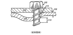
更なる技術的背景として、図3は、頭に隣接した逆ねじ山テーパに伴う特定の欠点をほぼ回避することにより保持強度及び振動による緩みに対する耐性を増大させる、例示的なねじ300を示している。該ねじ及びそれに関連する実施形態については、本出願と同日に出願された本出願人の「SELF-TAPPING SCREW AND METHOD FOR JOINING THIN WORKPIECES」(発明者:Alan Pritchard)と題する米国特許出願第09/952,091号に開示されている。端的に言えば、ねじ300は、頭302、テーパ付き谷底部分304(本体に沿って頭302に向かう方向で半径方向外方に向かってテーパが付けられたもの)、中央本体部分306、テーパ付きエントリ部分308、及び例示的なエントリポイント310(セルフドリリングポイント等)を含む。
II. 小葉型ブランクの成形
上述の原理(例えば、テーパ付き谷底部分及び多リードねじ山)は、多小葉型のねじ山を形成する断面を有するねじに一般に適用することができる。かかる多少葉型の断面は、丸くない(非円形の)周辺を画定する奇数個(3,5,7個等)の小葉から一般に構成される。一般に、小葉型ねじが、適当な大きさのパイロット孔にねじ込まれる際には、該小葉が材料を可塑的に変形させてロールフォーミングによるねじ山を形成する。かかるねじ山は、一定の度合いのスプリングバックに従う成形を維持し、これにより、振動による緩みを有利に低減させる保持圧がねじに加えられる。かかる小葉を3個有する多少葉型の断面の一例が、Research Engineering and Manufacturing Inc. (Middletown, RI and Conti Fastners AG of Switzerland) により開発され同社から入手可能なTrilobular (R) シリーズのセルフタッピングねじである。
III. ねじ形成
図9及び図10は、完成したねじ(符号902で示す)を作製するためのブランク405上のねじ山の形成を詳細に示したものである。この実施形態では、ねじ902は、頭410の直ぐ下でブランクの軸に沿って平坦なロールフォーミングダイ908,910により係合される。これらのダイは、一方のダイプレート908が他方のダイプレート910に対して横方向(矢印1002)に移動される際に、3つの部分(502,504,506)の各々におけるブランク表面の可塑的な変形を生じさせるのに十分な圧力(矢印912)を加える。該ダイプレートの移動中に、該ダイプレート間の間隔は、互いに対面するダイ形成面間の等距離の中央線により示すように一定に維持される。ダイが、偏心した断面のブランクに係合するため、該ダイ908の動きにより、振動するブランクの転動が生じることになる。詳細には、転動するブランク/ねじの中心軸512は、中心線1004の上下に交互に延びる経路1008をたどる。しかし、ダイ間の距離が一定であるため、平坦なアンビルマイクロメータを使用した断面の測定値は、完成したねじの外周全体について一定の大きさを示す傾向を有するものとなる。
IV. 結合アセンブリ
図14に詳細に示すように、完成した転動によるねじ902は、第1の薄い被加工物1402と第2の固定材用の被加工物1404とからなるアセンブリを共に結合させる。頭410は、第1の被加工物1402に対して堅く圧縮される。図示のように2つ又は3つ以上の別個の螺旋コイル、スクロール、又はリードねじ山1406,1408がねじ902に形成されている。これらは、ねじシャフトに沿って同じ軸方向位置に配置された直径方向で対向するねじ山輪郭1406,1408によって表されている。上述のように、完成したねじは、任意の小葉型の断面領域(3,5,9,11その他の個数の小葉)からなるものである。テーパ付き谷底部分906は、固定材1404に係合し、該固定材1404を前後方向に押し出して(押し出し位置1405を参照)、該固定材1404とねじ山1406等との間に更なるねじ係合を提供することに留意されたい。該押し出しは、部分的にはテーパ付き谷底部分におけるねじ山の谷が頭に向かって外方へテーパしているために生じ、一方、ねじ山の頂は、少なくとも本体部分の隣接部分の頂とほぼ同じ直径を維持する(及び頭の近くの断面が一層完全な円形になる)。このため、ねじが薄い固定材1404内に締め付けられるにつれて、該固定材1404が、図示するように、テーパ付き谷底部分のねじ山の谷に対して、軸方向前方及び後方に移動する位置へと次第に圧縮されていく。
Claims (12)
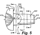
- 薄い被加工物(1402,1404)を結合させるためのねじ(300)であって、該ねじ(300)が所定の中心軸(512)の周りに形成された複数のリードねじ山(312)及び頭(302)を有しており、第1の被加工物(1402)が第2の被加工物(1404)上に載置され、該第2の被加工物(1404)が薄い固定材を画定し、該ねじ(300)が、多小葉型の断面を画定する本体部分(306)と、多小葉型の断面を画定する円錐ポイント部分(502)とを含み、
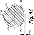
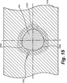
頭(302)に直ぐ隣接して配置されたテーパ付き谷底部分(304)であって、前記頭(302)と前記本体部分(306)との間にあり、及び変動する断面を画定し、該変動する断面が、前記頭(302)に隣接する最近円断面から前記小葉型の本体部分(306)に隣接する多小葉型の断面まで変動する、テーパ付き谷底部分(304)を特徴とし、
前記複数のリードねじ山(312)が、前記円錐ポイント部分(502)、前記本体部分(306)、及び前記テーパ付き谷底部分(304)に沿って配置され、及び一定のねじ山輪郭を有しており、前記中心軸(512)から各リードねじ山(312)の頂まで測定した半径方向距離が、前記テーパ付き谷底部分(304)と該テーパ付き谷底部分(304)に隣接する前記本体部分(306)の少なくとも一部とに沿って一定に維持され、
前記本体部分(306)、前記円錐ポイント部分(502)、及び前記テーパ付き谷底部分(304)の各々が、前記頭(302)から前記中心軸(512)に沿って前記第1の被加工物(1402)及び前記第2の被加工物(1404)を通って延びるよう構成され、前記リードねじ山(312)が、前記第2の被加工物(1404)と係合して、前記テーパ付き谷底部分(304)が該第2の被加工物(1404)に係合した状態で該第2の被加工物(1404)を前記第1の被加工物(1402)及び頭(302)に対して強制的に圧縮させるようになっている、ねじ(300)。 - 回転軸(512)に沿って測定した隣接するねじ山(312)の頂間の距離が軸方向ピッチ(P)を画定し、前記テーパ付き谷底部分(304)が該軸方向ピッチ(P)の少なくとも2倍の軸方向長さを有する、請求項1に記載のねじ(300)。
- 回転軸(512)に沿って測定した隣接するねじ山(312)の頂間の距離が軸方向ピッチ(P)を画定し、前記テーパ付き谷底部分(304)が該軸方向ピッチ(P)の3.5倍以下の軸方向長さを有する、請求項1に記載のねじ(300)。
- 請求項1ないし請求項4の何れか一項に記載のねじ(300)の使用方法であって、
所定の中心軸(512)の周りに形成されたねじ山(312)及び頭(302)を有するねじ(300)を使用して少なくとも第1の薄い被加工物(1402)と第2の薄い被加工物(1404)とを結合させ、該ねじ(300)が、多小葉型のねじ山形成断面を画定する本体部分(306)と、前記頭(302)に直ぐ隣接して配置されたテーパ付き谷底部分(304)であって、前記頭(302)と前記本体部分(306)との間にあり、及び該頭(302)に隣接する最近円断面から前記本体部分(306)に隣接する最大の小葉型を有する多小葉型の断面まで変動する断面を画定する、テーパ付き谷底部分(304)と、多小葉型のねじ山形成断面を画定する円錐ポイント部分(502)と、前記ねじ本体(306)及び前記テーパ付き谷底部分(304)に沿って配置された一定のねじ山輪郭(1406,1408)を有するリードねじ山(1406,1408)とを含み、前記回転軸(512)から各ねじ山の頂までの一定の半径方向距離が、前記テーパ付き谷底部分(304)と該テーパ付き谷底部分(304)に隣接する前記本体部分(306)の少なくとも一部との両方に沿って維持されており、該方法が、
ねじ(300)を回転させると共にその回転軸(512)に沿って前記第1の被加工物(1402)及び前記第2の被加工物(1404)の方向に圧力を加え、前記リードねじ山(1406,1408)が、前記テーパ付き谷底部分(304)において前記第2の被加工物(1404)と係合して、該第2の被加工物(1404)が前記第1の被加工物(1402)及び前記頭(302)を強制的に圧縮し、
前記第1の薄い被加工物(1402)が前記テーパ付き谷底部分(304)により画定される多小葉型の断面間で弛緩する際に外力による緩みに対する耐性を提供する、
ねじ(300)の使用方法。 - 前記ねじ(300)が、前記ねじ本体(306)に沿って配置された前記ねじ山によって一連の雌ねじ山(1406,1408)を形成する、請求項4に記載の薄い被加工物を結合させるための方法。
- 多小葉型のねじブランク上にねじ山を形成するための一対のロールフォーミングダイであって、
ねじ山をロールフォーミングするための1つ又は2つ以上の直線状の溝を有する第1のダイ(908)であって、その一端に向かう外方テーパを有し、該外方テーパが、ねじ頭に直ぐ隣接するねじブランクのテーパ付き谷底部分のねじ山のロールフォーミングを可能とするよう形成されている、第1のダイ(908)と、
該第1のダイ(908)と対面する第2のダイ(910)であって、該第1のダイが、該第2のダイ(910)との間に一定の間隔を置いて該第2のダイ(910)に対して移動可能であり、該第2のダイ(910)が、ねじ山をロールフォーミングするための1つ又は2つ以上の直線状の溝を有しており、及びその一端に向かう外方テーパを有しており、該外方テーパが、前記ねじブランクの前記テーパ付き谷底部分のねじ山のロールフォーミングを可能とするよう形成されている、第2のダイ(910)と
を含み、本体部分上のねじ山の外径と実質的に同じ外径のねじ山が、前記テーパ付き谷底部分に設けられ、
前記第1のダイ(908)の前記外方テーパ及び前記第2のダイ(910)の外方テーパが、それぞれ、前記テーパ付き谷底部分上にねじ山を形成するよう構成されており、該テーパ付き谷底部分が、前記頭へと向かう最近円部分から前記本体部分に隣接する最大小葉部分へと変化するものである、
一対のロールフォーミングダイ。 - 前記第1のダイ(908)及び前記第2のダイ(910)が、前記ねじブランク上に複数の別個のリードねじ山を形成するよう構成されている、請求項6に記載の一対のロールフォーミングダイ。
- 前記第1のダイ(908)の前記外方テーパ及び前記第2のダイ(910)の前記外方テーパが、それぞれ、前記テーパ付き谷底部分上にねじ山を形成するよう構成されており、該ねじ山が、前記本体部分上のねじ山の外径と実質的に同じ外径を有し、頂間におけるねじ山の谷が、前記本体部分から軸方向に前記頭に向かって連続的に増大する半径方向外方のテーパを画定する、請求項6又は請求項7に記載の一対のロールフォーミングダイ。
- 前記ブランクがヘッダダイ(402)により金属シャフトから形成され、該ヘッダダイ(402)が、
実質的に直線状のブランクを受容する成形用ダイキャビティ(404)であって、軸を通る断面を有し、及び、
i) 前記ブランクの頭に直ぐ隣接して円形の断面を画定し、及びそこから離隔して本体部分へと延びる、テーパ部分と、
ii) 多小葉型の断面を画定する本体部分と、
iii) 該本体部分から延び、及び多小葉型の断面を画定する、円錐ポイント部分と
を画定するダイ内壁を含む、成形用ダイキャビティ(404)を含む、
請求項6ないし請求項8の何れか一項に記載の一対のロールフォーミングダイ。 - 請求項6ないし請求項9の何れか一項に記載のロールフォーミングダイを用いて薄い被加工物を結合させるためのねじを作成するための方法であって、
一対のダイ間に小葉型の本体部分を有する頭付きブランクを挿入し、該一対のダイの各々の一方の側に設けられた一組の直線状の溝及びテーパ領域が、前記頭付きブランクの頭に直ぐ隣接してその円形のテーパ部分上に配置されるよう構成されており、
前記一対のダイから前記頭付きブランクに圧縮力を加え、
前記一対のダイの一方を直線方向に移動させることにより前記頭付きブランクを該一対のダイ間で転動させ、これにより該ブランクの中心軸が前記ダイ間の空間の中心線に対して振動する経路を画定し、該ダイが前記頭付きブランクを可塑的に変形させることにより前記ねじ本体と前記テーパ部分上のテーパ付き谷底部分との上に一組のねじ山を形成し、
前記本体部分上のねじ山の外径と実質的に同じ外径のねじ山が前記テーパ付き谷底部分に設けられ、
前記頭付きブランクの前記テーパ付き谷底部分に沿って可変断面を形成し、該可変断面が、前記頭に隣接する最近円断面から前記本体に隣接する最大小葉型断面まで変動するものである、
ねじの作成方法。 - 前記移動ステップが、少なくとも2つの別個のリードねじ山を前記頭付きブランク上に形成することを含む、請求項10に記載の方法。
- 金属シャフトにヘッダダイを適用することにより頭付きブランクを成形するステップを更に含み、該ヘッダダイが、
実質的に直線状のブランクを受容する成形用ダイキャビティであって、軸を通る断面を有し、及び、
i) 前記ブランクの頭に近接して円形の断面を画定し、及びそこから離隔して本体部分へと延びる、テーパ部分と、
ii) 多小葉型の断面を画定する本体部分と、
iii) 該本体部分から延び、及び多小葉型の断面を画定する、円錐ポイント部分と
を画定するダイ内壁を含む、成形用ダイキャビティを含むものである、
請求項10又は請求項11の何れか一項に記載の方法。
Applications Claiming Priority (2)
| Application Number | Priority Date | Filing Date | Title |
|---|---|---|---|
| US09/952,157 US6494656B1 (en) | 2001-09-13 | 2001-09-13 | Self-tapping screw, blank and method for joining thin workpieces and production method for the same |
| PCT/EP2002/008960 WO2003023239A1 (en) | 2001-09-13 | 2002-08-09 | Self-tapping screw, blank, method and dies for making the same and method for joining thin workpieces |
Publications (3)
| Publication Number | Publication Date |
|---|---|
| JP2005502835A JP2005502835A (ja) | 2005-01-27 |
| JP2005502835A5 JP2005502835A5 (ja) | 2006-01-05 |
| JP4480395B2 true JP4480395B2 (ja) | 2010-06-16 |
Family
ID=25492634
Family Applications (1)
| Application Number | Title | Priority Date | Filing Date |
|---|---|---|---|
| JP2003527277A Expired - Lifetime JP4480395B2 (ja) | 2001-09-13 | 2002-08-09 | 薄い被加工物を結合させるためのセルフタッピングねじ、ブランク、方法、及びそれらを作成するためのダイ及び方法 |
Country Status (11)
| Country | Link |
|---|---|
| US (2) | US6494656B1 (ja) |
| EP (1) | EP1425514B1 (ja) |
| JP (1) | JP4480395B2 (ja) |
| KR (1) | KR100959296B1 (ja) |
| CN (1) | CN1306174C (ja) |
| AT (1) | ATE328210T1 (ja) |
| CA (1) | CA2446242C (ja) |
| DE (1) | DE60211920T2 (ja) |
| ES (1) | ES2269752T3 (ja) |
| SG (1) | SG125144A1 (ja) |
| WO (1) | WO2003023239A1 (ja) |
Cited By (1)
| Publication number | Priority date | Publication date | Assignee | Title |
|---|---|---|---|---|
| US9267528B2 (en) | 2012-06-26 | 2016-02-23 | Topura Co., Ltd. | Tapping screw |
Families Citing this family (33)
| Publication number | Priority date | Publication date | Assignee | Title |
|---|---|---|---|---|
| GB9926968D0 (en) * | 1999-11-15 | 2000-01-12 | Univ London | Treatment of neurological disorders |
| US6799483B2 (en) * | 2001-05-15 | 2004-10-05 | Patrick Andreas Petri | Method and mechanism for converting vibration induced rotation into translational motion |
| US20030210970A1 (en) * | 2002-03-26 | 2003-11-13 | Bechtel Frank W. | Radius gimlet point anti-stripout screw |
| US6940209B2 (en) * | 2003-09-08 | 2005-09-06 | New Scale Technologies | Ultrasonic lead screw motor |
| US7170214B2 (en) | 2003-09-08 | 2007-01-30 | New Scale Technologies, Inc. | Mechanism comprised of ultrasonic lead screw motor |
| US7309943B2 (en) * | 2003-09-08 | 2007-12-18 | New Scale Technologies, Inc. | Mechanism comprised of ultrasonic lead screw motor |
| DE102004034246B4 (de) * | 2004-07-15 | 2008-04-24 | Sfs Intec Holding Ag | Schraube |
| US20060090325A1 (en) * | 2004-11-02 | 2006-05-04 | Bernard Jeremy R | Vehicle powertrain joints comprising self-tapping fasteners |
| WO2007048267A1 (de) * | 2005-10-28 | 2007-05-03 | Medartis, Ag | Gewinde formende schraube |
| DE102008033509A1 (de) * | 2008-07-07 | 2010-01-14 | Arnold Umformtechnik Gmbh & Co. Kg | Schraube |
| DE102009002078A1 (de) * | 2009-04-01 | 2010-10-07 | Ford Global Technologies, LLC, Dearborn | Verbindungsvorrichtung |
| DE102010000702A1 (de) * | 2010-01-06 | 2011-07-07 | Arnold Umformtechnik GmbH & Co. KG, 74670 | Gewindeformende Schraube und ihre Verwendung |
| US8529178B2 (en) | 2010-02-19 | 2013-09-10 | Nucor Corporation | Weldless building structures |
| US9004835B2 (en) | 2010-02-19 | 2015-04-14 | Nucor Corporation | Weldless building structures |
| IT1403796B1 (it) * | 2011-01-12 | 2013-10-31 | Savio Spa | "sistema di fissaggio di accessori su telai in materiale metallico per porte, finestre e simili" |
| JP2012182378A (ja) * | 2011-03-02 | 2012-09-20 | Tokyo Electron Ltd | プローブカードの位置決め機構及び検査装置 |
| PL2657547T3 (pl) * | 2012-04-24 | 2014-08-29 | Nedschroef Fraulautern Gmbh | Śruba |
| US9016994B2 (en) * | 2013-02-11 | 2015-04-28 | James Michael Platt | Threaded fastener |
| DE102013106758B4 (de) | 2013-06-27 | 2022-06-09 | Aesculap Aktiengesellschaft | Unrunde Pedikelschraube |
| TWI555920B (zh) * | 2014-07-17 | 2016-11-01 | Screw structure improvement | |
| US9488210B2 (en) * | 2014-09-30 | 2016-11-08 | Ford Global Technologies, Llc | Flow drill screw assembly and method |
| JP5770399B1 (ja) * | 2015-03-02 | 2015-08-26 | クラウン精密工業株式会社 | 自己タップねじ及びその製造方法 |
| US10125805B2 (en) * | 2015-04-21 | 2018-11-13 | Sungwoo Hitech Co., Ltd | Rivet screw drill |
| CN105134731B (zh) * | 2015-09-25 | 2017-04-12 | 安徽工程大学 | 一种紧定于金属薄壁壳体的无螺纹塑料自攻螺钉 |
| DE102015222281A1 (de) * | 2015-11-12 | 2017-05-18 | Arnold Umformtechnik Gmbh & Co. Kg | Gewindeformende Schraube |
| WO2017102290A1 (en) * | 2015-12-15 | 2017-06-22 | Electrolux Appliances Aktiebolag | Cooking oven |
| CA3211072A1 (en) | 2016-05-02 | 2017-11-02 | Asia Fastening (Us), Inc. | Double threaded standoff fastener |
| DE102016211444A1 (de) * | 2016-06-27 | 2017-12-28 | Arnold Umformtechnik Gmbh & Co. Kg | Verbindungselement und Verfahren zum Verbinden mindestens zweier Werkstücke |
| CN107816483A (zh) * | 2017-02-05 | 2018-03-20 | 超捷紧固系统(上海)股份有限公司 | 公制自攻防松螺钉及其制造方法 |
| TWI622710B (zh) * | 2017-05-02 | 2018-05-01 | 徐敏豪 | 薄鐵板用的螺絲 |
| US11686337B2 (en) | 2018-12-31 | 2023-06-27 | Robert E. Stewart | Faceted lobular threads |
| IT201900022686A1 (it) * | 2019-12-02 | 2021-06-02 | Wm System Srl | Vite e metodo di assemblaggio mediante detta vite |
| WO2023077011A1 (en) * | 2021-10-27 | 2023-05-04 | Semblex Corporation | Torque reducing flow drilling fastener for thick materials and method of using such fastener |
Family Cites Families (41)
| Publication number | Priority date | Publication date | Assignee | Title |
|---|---|---|---|---|
| US23409A (en) | 1859-03-29 | Improved manufacture of wood-screws | ||
| US1872166A (en) | 1930-11-06 | 1932-08-16 | Muhlig Ludwik | Screw |
| US3918345A (en) * | 1961-06-27 | 1975-11-11 | Res Eng & Mfg | Thread forming fasteners |
| GB1022355A (en) * | 1962-08-31 | 1966-03-09 | Res Eng & Mfg | Self-tapping screw with lobular work-entering end and methods for manufacturing same |
| US3180126A (en) * | 1962-11-14 | 1965-04-27 | Textron Ind Inc | Self-tapping screw and method of manufacture |
| US3978760A (en) * | 1970-01-19 | 1976-09-07 | Research Engineering & Manufacturing, Inc. | Self-thread forming threaded fasteners and blanks for making same |
| US3945272A (en) * | 1970-01-30 | 1976-03-23 | Nl Industries Inc. | Thread-rolling method, thread-rolling dies, and method of manufacturing the dies |
| US3661046A (en) | 1970-11-09 | 1972-05-09 | Illinois Tool Works | Combination screw |
| US3812639A (en) | 1973-03-26 | 1974-05-28 | Illinois Tool Works | Locking and strip-resistant fastener |
| US3949641A (en) | 1974-11-04 | 1976-04-13 | The Steel Company Of Canada, Limited | Self-drilling screw |
| GB1537701A (en) | 1976-01-09 | 1979-01-04 | Avdel Ltd | Drills and self-drilling screws |
| US4034586A (en) * | 1976-05-24 | 1977-07-12 | Colt Industries Operating Corporation | Thread rolling die and method of thread rolling |
| US4310272A (en) * | 1980-01-18 | 1982-01-12 | Textron Inc. | Threaded fastener and structural joint attained therewith |
| US4368552A (en) | 1980-11-04 | 1983-01-18 | Crown Screw Corporation | Method of making self tapping thread forming screw |
| JPS589513U (ja) * | 1981-07-14 | 1983-01-21 | 株式会社青山製作所 | タツピンねじ |
| DE3272798D1 (en) * | 1982-02-18 | 1986-10-02 | Conti Fasteners Ag | Screw |
| DE3332570A1 (de) * | 1983-09-09 | 1985-03-28 | Friedr. Boesner GmbH, 5450 Neuwied | Verfahren zur herstellung von selbstformenden und selbstsichernden schrauben mit zusaetzlicher abdicht- und/oder stell-eigenschaft |
| US5252016A (en) | 1989-11-13 | 1993-10-12 | Isolink Inc. | Fixing element for low strength materials |
| US5061135A (en) | 1990-08-28 | 1991-10-29 | Research Engineering & Manufacturing, Inc. | Thread tapping screw |
| US5356253A (en) * | 1992-04-29 | 1994-10-18 | Whitesell Neil L | Sheet metal screw |
| US5183359A (en) | 1992-05-12 | 1993-02-02 | Illinois Tool Works Inc. | Rotary fastener with anti-strip-out nibs |
| CA2125357C (en) | 1993-06-09 | 1999-01-12 | David James Roberts | Self-drilling screw |
| US5456685A (en) | 1994-02-14 | 1995-10-10 | Smith & Nephew Dyonics, Inc. | Interference screw having a tapered back root |
| US5518352A (en) | 1994-10-17 | 1996-05-21 | Lieggi; Martin | Relief screw |
| CN2215621Y (zh) * | 1994-12-22 | 1995-12-20 | 胡来忠 | 一种带齿牙的铁钉 |
| JPH08226424A (ja) * | 1995-02-18 | 1996-09-03 | Terufumi Nojigawa | タッピンねじおよびその製造方法 |
| US5599149A (en) | 1995-02-28 | 1997-02-04 | Anchor Bolt And Screw Company | Self-tapping floor screw |
| JP3046746B2 (ja) * | 1995-06-14 | 2000-05-29 | ミネベア株式会社 | ねじ及びねじの製造方法 |
| JP3050789B2 (ja) * | 1996-01-08 | 2000-06-12 | 株式会社青山製作所 | タッピンねじ |
| US6319270B1 (en) | 1996-08-05 | 2001-11-20 | Arthrex, Inc. | Headed bioabsorbable tissue anchor |
| US5722808A (en) | 1996-09-11 | 1998-03-03 | Conti Fasteners Ag | Threaded fastener system |
| KR100276352B1 (ko) * | 1996-11-29 | 2000-12-15 | 하시모토 히사오 | 구동나사 |
| CN1045814C (zh) * | 1997-01-21 | 1999-10-20 | 陈河田 | 尖锥部具有多头不同导程螺牙的自攻牙螺钉 |
| JP3934165B2 (ja) | 1997-07-29 | 2007-06-20 | エヨト フェルビンドゥングステヒニク ゲーエムベーハー ウント ツェーオー カーゲー | タッピンねじを備えたねじ |
| JP3020904B2 (ja) * | 1997-11-06 | 2000-03-15 | クラウン精密工業株式会社 | 自己タップねじ |
| US5909992A (en) | 1998-07-02 | 1999-06-08 | Wu; Tsan-Hsing | Self-tapping screw for fastening a metal corrugated board |
| US5921735A (en) * | 1998-08-19 | 1999-07-13 | Phillips Screw Company | Lobular fastener with rectilinear pitch profile |
| DE19857311A1 (de) * | 1998-12-11 | 2000-06-15 | Ejot Verbindungstech Gmbh & Co | Selbstfurchende Schraube |
| US6089806A (en) | 1999-01-25 | 2000-07-18 | Conti Fasteners | Blank for self-tapping fastener |
| US6045312A (en) * | 1999-03-17 | 2000-04-04 | Illinois Tool Works Inc. | Fastener having primary and secondary threads |
| JP4294802B2 (ja) * | 1999-07-30 | 2009-07-15 | 日本パワーファスニング株式会社 | 薄板締結用の座金付きドリルねじ |
-
2001
- 2001-09-13 US US09/952,157 patent/US6494656B1/en not_active Expired - Lifetime
-
2002
- 2002-08-09 KR KR1020047003648A patent/KR100959296B1/ko active IP Right Grant
- 2002-08-09 ES ES02758456T patent/ES2269752T3/es not_active Expired - Lifetime
- 2002-08-09 WO PCT/EP2002/008960 patent/WO2003023239A1/en active IP Right Grant
- 2002-08-09 JP JP2003527277A patent/JP4480395B2/ja not_active Expired - Lifetime
- 2002-08-09 CN CNB02811602XA patent/CN1306174C/zh not_active Expired - Lifetime
- 2002-08-09 AT AT02758456T patent/ATE328210T1/de not_active IP Right Cessation
- 2002-08-09 DE DE60211920T patent/DE60211920T2/de not_active Expired - Lifetime
- 2002-08-09 CA CA2446242A patent/CA2446242C/en not_active Expired - Lifetime
- 2002-08-09 SG SG200500999A patent/SG125144A1/en unknown
- 2002-08-09 EP EP02758456A patent/EP1425514B1/en not_active Expired - Lifetime
- 2002-10-03 US US10/264,195 patent/US6712708B2/en not_active Expired - Lifetime
Cited By (1)
| Publication number | Priority date | Publication date | Assignee | Title |
|---|---|---|---|---|
| US9267528B2 (en) | 2012-06-26 | 2016-02-23 | Topura Co., Ltd. | Tapping screw |
Also Published As
| Publication number | Publication date |
|---|---|
| DE60211920T2 (de) | 2006-10-19 |
| WO2003023239A1 (en) | 2003-03-20 |
| KR100959296B1 (ko) | 2010-05-26 |
| CA2446242A1 (en) | 2003-03-20 |
| CN1306174C (zh) | 2007-03-21 |
| DE60211920D1 (de) | 2006-07-06 |
| ES2269752T3 (es) | 2007-04-01 |
| SG125144A1 (en) | 2006-09-29 |
| CN1527908A (zh) | 2004-09-08 |
| EP1425514A1 (en) | 2004-06-09 |
| JP2005502835A (ja) | 2005-01-27 |
| CA2446242C (en) | 2010-10-26 |
| ATE328210T1 (de) | 2006-06-15 |
| US6712708B2 (en) | 2004-03-30 |
| EP1425514B1 (en) | 2006-05-31 |
| US6494656B1 (en) | 2002-12-17 |
| US20030049095A1 (en) | 2003-03-13 |
| KR20040039350A (ko) | 2004-05-10 |
Similar Documents
| Publication | Publication Date | Title |
|---|---|---|
| JP4480395B2 (ja) | 薄い被加工物を結合させるためのセルフタッピングねじ、ブランク、方法、及びそれらを作成するためのダイ及び方法 | |
| US6089806A (en) | Blank for self-tapping fastener | |
| US3978760A (en) | Self-thread forming threaded fasteners and blanks for making same | |
| US3878759A (en) | Bi-lobular self-thread forming fastener | |
| CN100416114C (zh) | 攻丝辅助固定元件和方法 | |
| JP2005502835A5 (ja) | ||
| US3530760A (en) | Thread-forming screw | |
| US3935785A (en) | Thread swaging screw | |
| US3875780A (en) | Method of making a thread forming screw | |
| US3996834A (en) | Fastening element | |
| JPH0663531B2 (ja) | スターファスナーの改良 | |
| JP2004504944A (ja) | 軽量ねじ締結具およびねじ転造ダイス | |
| JPH0646044B2 (ja) | 非対称形状のねじ山成形用ねじと、その製造方法 | |
| US3218905A (en) | Self-tapping or thread-forming screw | |
| CA2077733C (en) | Thread forming method and apparatus | |
| EP1270963B1 (en) | Fastener | |
| CN104963927A (zh) | 一种翻铆自锁螺母及其加工方法 | |
| US5182937A (en) | Seam-free thread rolling dies | |
| US6135892A (en) | Method of forming a short point anti-cross threading member | |
| JPS6025213B2 (ja) | ねじ山の形の内側に閉じられた螺旋空洞を有する弾性ねじの製造方法と工具 | |
| TW202144099A (zh) | 用於製造異型桿之方法 | |
| TW201447119A (zh) | 螺絲和混凝上螺絲的製造方法 | |
| RU30639U1 (ru) | Резьбонакатывающая крепежная деталь, инструмент для ее изготовления | |
| TWI224655B (en) | Clinch-type blind nut | |
| GB1562385A (en) | Thread forming members |
Legal Events
| Date | Code | Title | Description |
|---|---|---|---|
| A521 | Request for written amendment filed |
Free format text: JAPANESE INTERMEDIATE CODE: A523 Effective date: 20050808 |
|
| A621 | Written request for application examination |
Free format text: JAPANESE INTERMEDIATE CODE: A621 Effective date: 20050808 |
|
| A131 | Notification of reasons for refusal |
Free format text: JAPANESE INTERMEDIATE CODE: A131 Effective date: 20080729 |
|
| A601 | Written request for extension of time |
Free format text: JAPANESE INTERMEDIATE CODE: A601 Effective date: 20081028 |
|
| A602 | Written permission of extension of time |
Free format text: JAPANESE INTERMEDIATE CODE: A602 Effective date: 20081105 |
|
| A521 | Request for written amendment filed |
Free format text: JAPANESE INTERMEDIATE CODE: A523 Effective date: 20090113 |
|
| A131 | Notification of reasons for refusal |
Free format text: JAPANESE INTERMEDIATE CODE: A131 Effective date: 20090303 |
|
| A601 | Written request for extension of time |
Free format text: JAPANESE INTERMEDIATE CODE: A601 Effective date: 20090603 |
|
| A602 | Written permission of extension of time |
Free format text: JAPANESE INTERMEDIATE CODE: A602 Effective date: 20090610 |
|
| A521 | Request for written amendment filed |
Free format text: JAPANESE INTERMEDIATE CODE: A523 Effective date: 20090723 |
|
| A131 | Notification of reasons for refusal |
Free format text: JAPANESE INTERMEDIATE CODE: A131 Effective date: 20090929 |
|
| A521 | Request for written amendment filed |
Free format text: JAPANESE INTERMEDIATE CODE: A523 Effective date: 20091224 |
|
| TRDD | Decision of grant or rejection written | ||
| A01 | Written decision to grant a patent or to grant a registration (utility model) |
Free format text: JAPANESE INTERMEDIATE CODE: A01 Effective date: 20100302 |
|
| A01 | Written decision to grant a patent or to grant a registration (utility model) |
Free format text: JAPANESE INTERMEDIATE CODE: A01 |
|
| A61 | First payment of annual fees (during grant procedure) |
Free format text: JAPANESE INTERMEDIATE CODE: A61 Effective date: 20100316 |
|
| FPAY | Renewal fee payment (event date is renewal date of database) |
Free format text: PAYMENT UNTIL: 20130326 Year of fee payment: 3 |
|
| R150 | Certificate of patent or registration of utility model |
Ref document number: 4480395 Country of ref document: JP Free format text: JAPANESE INTERMEDIATE CODE: R150 Free format text: JAPANESE INTERMEDIATE CODE: R150 |
|
| FPAY | Renewal fee payment (event date is renewal date of database) |
Free format text: PAYMENT UNTIL: 20130326 Year of fee payment: 3 |
|
| FPAY | Renewal fee payment (event date is renewal date of database) |
Free format text: PAYMENT UNTIL: 20140326 Year of fee payment: 4 |
|
| R250 | Receipt of annual fees |
Free format text: JAPANESE INTERMEDIATE CODE: R250 |
|
| R250 | Receipt of annual fees |
Free format text: JAPANESE INTERMEDIATE CODE: R250 |
|
| R250 | Receipt of annual fees |
Free format text: JAPANESE INTERMEDIATE CODE: R250 |
|
| R250 | Receipt of annual fees |
Free format text: JAPANESE INTERMEDIATE CODE: R250 |
|
| R250 | Receipt of annual fees |
Free format text: JAPANESE INTERMEDIATE CODE: R250 |
|
| R250 | Receipt of annual fees |
Free format text: JAPANESE INTERMEDIATE CODE: R250 |
|
| R250 | Receipt of annual fees |
Free format text: JAPANESE INTERMEDIATE CODE: R250 |
|
| R250 | Receipt of annual fees |
Free format text: JAPANESE INTERMEDIATE CODE: R250 |
|
| R250 | Receipt of annual fees |
Free format text: JAPANESE INTERMEDIATE CODE: R250 |
|
| R250 | Receipt of annual fees |
Free format text: JAPANESE INTERMEDIATE CODE: R250 |
|
| EXPY | Cancellation because of completion of term |