JP4480395B2 - Self-tapping screws, blanks, methods, and dies and methods for making them for joining thin workpieces - Google Patents
Self-tapping screws, blanks, methods, and dies and methods for making them for joining thin workpieces Download PDFInfo
- Publication number
- JP4480395B2 JP4480395B2 JP2003527277A JP2003527277A JP4480395B2 JP 4480395 B2 JP4480395 B2 JP 4480395B2 JP 2003527277 A JP2003527277 A JP 2003527277A JP 2003527277 A JP2003527277 A JP 2003527277A JP 4480395 B2 JP4480395 B2 JP 4480395B2
- Authority
- JP
- Japan
- Prior art keywords
- screw
- thread
- section
- die
- tapered
- Prior art date
- Legal status (The legal status is an assumption and is not a legal conclusion. Google has not performed a legal analysis and makes no representation as to the accuracy of the status listed.)
- Expired - Lifetime
Links
- 238000000034 method Methods 0.000 title claims abstract description 14
- 238000005304 joining Methods 0.000 title claims abstract description 7
- 238000010079 rubber tapping Methods 0.000 title abstract description 18
- 239000000463 material Substances 0.000 claims abstract description 27
- 238000000465 moulding Methods 0.000 claims description 10
- 230000004323 axial length Effects 0.000 claims description 4
- 239000002184 metal Substances 0.000 claims description 4
- 230000008878 coupling Effects 0.000 claims description 2
- 238000010168 coupling process Methods 0.000 claims description 2
- 238000005859 coupling reaction Methods 0.000 claims description 2
- 238000004519 manufacturing process Methods 0.000 abstract description 6
- 238000005096 rolling process Methods 0.000 description 5
- 230000015572 biosynthetic process Effects 0.000 description 4
- 238000004873 anchoring Methods 0.000 description 3
- 230000008569 process Effects 0.000 description 3
- 238000013459 approach Methods 0.000 description 2
- 230000014759 maintenance of location Effects 0.000 description 2
- 230000007246 mechanism Effects 0.000 description 2
- 238000007493 shaping process Methods 0.000 description 2
- 230000009471 action Effects 0.000 description 1
- 238000007792 addition Methods 0.000 description 1
- 230000009286 beneficial effect Effects 0.000 description 1
- 230000015556 catabolic process Effects 0.000 description 1
- 230000008859 change Effects 0.000 description 1
- 239000003795 chemical substances by application Substances 0.000 description 1
- 238000006731 degradation reaction Methods 0.000 description 1
- 230000032798 delamination Effects 0.000 description 1
- 238000013461 design Methods 0.000 description 1
- 238000009826 distribution Methods 0.000 description 1
- 238000005553 drilling Methods 0.000 description 1
- 230000000694 effects Effects 0.000 description 1
- 238000001125 extrusion Methods 0.000 description 1
- 238000005259 measurement Methods 0.000 description 1
- 230000003534 oscillatory effect Effects 0.000 description 1
- 230000000750 progressive effect Effects 0.000 description 1
- 230000009467 reduction Effects 0.000 description 1
- 238000011160 research Methods 0.000 description 1
- 230000009466 transformation Effects 0.000 description 1
Images


Classifications
-
- F—MECHANICAL ENGINEERING; LIGHTING; HEATING; WEAPONS; BLASTING
- F16—ENGINEERING ELEMENTS AND UNITS; GENERAL MEASURES FOR PRODUCING AND MAINTAINING EFFECTIVE FUNCTIONING OF MACHINES OR INSTALLATIONS; THERMAL INSULATION IN GENERAL
- F16B—DEVICES FOR FASTENING OR SECURING CONSTRUCTIONAL ELEMENTS OR MACHINE PARTS TOGETHER, e.g. NAILS, BOLTS, CIRCLIPS, CLAMPS, CLIPS OR WEDGES; JOINTS OR JOINTING
- F16B25/00—Screws that cut thread in the body into which they are screwed, e.g. wood screws
-
- B—PERFORMING OPERATIONS; TRANSPORTING
- B21—MECHANICAL METAL-WORKING WITHOUT ESSENTIALLY REMOVING MATERIAL; PUNCHING METAL
- B21H—MAKING PARTICULAR METAL OBJECTS BY ROLLING, e.g. SCREWS, WHEELS, RINGS, BARRELS, BALLS
- B21H3/00—Making helical bodies or bodies having parts of helical shape
- B21H3/02—Making helical bodies or bodies having parts of helical shape external screw-threads ; Making dies for thread rolling
- B21H3/027—Rolling of self-tapping screws
-
- F—MECHANICAL ENGINEERING; LIGHTING; HEATING; WEAPONS; BLASTING
- F16—ENGINEERING ELEMENTS AND UNITS; GENERAL MEASURES FOR PRODUCING AND MAINTAINING EFFECTIVE FUNCTIONING OF MACHINES OR INSTALLATIONS; THERMAL INSULATION IN GENERAL
- F16B—DEVICES FOR FASTENING OR SECURING CONSTRUCTIONAL ELEMENTS OR MACHINE PARTS TOGETHER, e.g. NAILS, BOLTS, CIRCLIPS, CLAMPS, CLIPS OR WEDGES; JOINTS OR JOINTING
- F16B25/00—Screws that cut thread in the body into which they are screwed, e.g. wood screws
- F16B25/001—Screws that cut thread in the body into which they are screwed, e.g. wood screws characterised by the material of the body into which the screw is screwed
- F16B25/0021—Screws that cut thread in the body into which they are screwed, e.g. wood screws characterised by the material of the body into which the screw is screwed the material being metal, e.g. sheet-metal or aluminium
-
- F—MECHANICAL ENGINEERING; LIGHTING; HEATING; WEAPONS; BLASTING
- F16—ENGINEERING ELEMENTS AND UNITS; GENERAL MEASURES FOR PRODUCING AND MAINTAINING EFFECTIVE FUNCTIONING OF MACHINES OR INSTALLATIONS; THERMAL INSULATION IN GENERAL
- F16B—DEVICES FOR FASTENING OR SECURING CONSTRUCTIONAL ELEMENTS OR MACHINE PARTS TOGETHER, e.g. NAILS, BOLTS, CIRCLIPS, CLAMPS, CLIPS OR WEDGES; JOINTS OR JOINTING
- F16B25/00—Screws that cut thread in the body into which they are screwed, e.g. wood screws
- F16B25/0036—Screws that cut thread in the body into which they are screwed, e.g. wood screws characterised by geometric details of the screw
- F16B25/0078—Screws that cut thread in the body into which they are screwed, e.g. wood screws characterised by geometric details of the screw with a shaft of non-circular cross-section or other special geometric features of the shaft
-
- F—MECHANICAL ENGINEERING; LIGHTING; HEATING; WEAPONS; BLASTING
- F16—ENGINEERING ELEMENTS AND UNITS; GENERAL MEASURES FOR PRODUCING AND MAINTAINING EFFECTIVE FUNCTIONING OF MACHINES OR INSTALLATIONS; THERMAL INSULATION IN GENERAL
- F16B—DEVICES FOR FASTENING OR SECURING CONSTRUCTIONAL ELEMENTS OR MACHINE PARTS TOGETHER, e.g. NAILS, BOLTS, CIRCLIPS, CLAMPS, CLIPS OR WEDGES; JOINTS OR JOINTING
- F16B35/00—Screw-bolts; Stay-bolts; Screw-threaded studs; Screws; Set screws
- F16B35/04—Screw-bolts; Stay-bolts; Screw-threaded studs; Screws; Set screws with specially-shaped head or shaft in order to fix the bolt on or in an object
- F16B35/041—Specially-shaped shafts
Abstract
Description
本発明は、セルフタッピングねじに関し、特に、セルフタッピングねじ、セルフタッピングねじ用のブランク、及び適当なロールフォーミングダイを使用してセルフタッピングねじを形成するための方法に関するものである。 The present invention relates to self-tapping screws, and more particularly to a method for forming self-tapping screws using self-tapping screws, blanks for self-tapping screws, and suitable roll forming dies.
従来のセルフタッピングねじ製品は、薄いシート状の金属部品の組み立てに使用する場合に、ねじ締付けトルクを比較的小さい値に抑制する必要性に伴う問題に起因して、その作用の信頼性が不十分なものとなる、ということが当業者に認識されている。締付けトルクに必要とされる抑制は、組み立て中に固定材が剥離してねじが空回りする可能性を最小限にするために必要である。固定材は、結合される組み立て部品のうち、ねじ頭の下側から最も遠くに移動する部分である。かかる剥離及び空回りは、アセンブリのクランプ負荷を失わせ、続いてアセンブリの劣化を生じさせるものとなる。 Conventional self-tapping screw products, when used for assembling thin sheet metal parts, are unreliable due to problems associated with the need to keep the screw tightening torque relatively low. Those skilled in the art will recognize that this will be sufficient. The restraint required for the tightening torque is necessary to minimize the possibility that the fixing material will peel off during assembly and the screw will idle. The fixing member is a part of the assembled part to be moved farthest from the lower side of the screw head. Such delamination and idling can cause the assembly to lose its clamping load and subsequently cause degradation of the assembly.
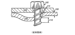
図1は、従来の、薄いシート状の金属部品104,106を結合して1つの結合されたアセンブリにするために使用される従来の一条ねじ山を有するセルフタッピングねじ102に共通して生じる欠点を示している。該ねじは、従来の円形の断面を含むものである。
FIG. 1 illustrates the disadvantages commonly associated with a conventional self-tapping
ねじ頭から最も離れて位置するねじ固定材106は、ねじの軸方向ピッチ110と同じか又はそれよりも小さい幅108を有するものであり(本書では概して「薄い」被加工物と称す)、一般に螺旋又はねじ山の前面112が固定材106を変形させ、該固定材は、隣接する螺旋、スクロール、又はねじ山間の間隔に従うようになる。この種の固定材及びアセンブリは、最も効果的な結合クランプ負荷を生じさせることができない。加えて、不適切なねじ山の係合接触が生じることになる。
The
一条ねじ山構成の特定の欠点を克服するために、薄い材料を結合するために使用する際には、頭付きブランクの周囲に形成された多条ねじ山を有する断面が真円のねじが、最近使用されてきた。多条ねじの使用は、固定材を一層良好に捉える傾向を有するものとなり、これにより、固定材のパイロット孔の周囲の複数の場所での一層分散した係合が提供されて、固定材がねじ山間に捕捉されることが防止される。 To overcome certain disadvantages of the single thread configuration, when used to bond thin materials, a thread with a round cross section having a multi-thread thread formed around a headed blank, It has been used recently. The use of multi-threaded screws tends to better capture the fixing material, thereby providing more distributed engagement at multiple locations around the pilot hole in the fixing material, so that the fixing material is threaded. It is prevented from being trapped in the mountains.
しかし、多条ねじを使用する場合であっても、該多条ねじの単独での使用は完璧な解決策とはならない。図2は、薄い被加工物を結合させる場合における、(断面が円形又は非円形の)一条ねじ山又は多条ねじ山を有する従来のねじに関する依然と存在する欠点を明らかに示したものである。典型的なねじ200は、ねじ頭206の下側204に対して可能な限り近接して平行なコア直径202を維持するものである。この実施形態は、アセンブリの性能を低下させ得るものである。製造上の制約により、一般に、ねじ頭206の下側204に隣接してねじ山の頂の充填不足が生じ、このため、不特定の調整することができないねじ山の逆テーパ208が生じることになる。かかる場合、ねじのエントリポイントに一層近いねじ山の頂は、ねじ頭に一層近いねじ山の頂よりも直径が大きくなる。このねじ山の逆テーパ208は、アセンブリの雌ねじと雄ねじとの間にギャップ210を生じさせるという欠点を有するものである。このギャップ210は、結合された構造体の重要な領域におけるねじの係合接触が低減するという結果を招き、その結果として、予想される適用トルクを下回るトルクでアセンブリが破壊されることになる。
However, even when multiple threads are used, the use of the multiple threads alone is not a perfect solution. FIG. 2 clearly illustrates the still existing drawbacks associated with conventional screws with single or multiple threads (circular or non-circular cross-section) when joining thin workpieces. . A
(上述したような)円形断面のねじを使用することがこれまで好まれてきた。非円形断面のねじを使用してねじ山の形成で特定の利点を達成することが可能であるが、一般に、非円形断面(市販のロールフォーミングセルフタッピング多葉型ねじ等)の使用は、アセンブリにとって不利であると考えられてきた。かかる非円形断面は、1つのアセンブリへと結合された際に加えられるトルクに対して必要とされる抵抗強度に欠けるものと見なされている。 The use of circular cross-section screws (as described above) has been preferred so far. Although it is possible to achieve certain advantages in thread formation using non-circular cross-section screws, in general, the use of non-circular cross-sections (such as commercially available roll-forming self-tapping multileaf screws) Has been considered disadvantageous to Such non-circular cross-sections are considered lacking the required strength of resistance to torque applied when combined into one assembly.
したがって、本発明の目的は、非円形断面のブランクを使用してかかるねじを形成し、これにより有利なねじ山形成特性及び望ましい多葉ねじ山を有する有利な多葉ねじを作製するための、セルフタッピングねじ及びそれに関連する方法を提供することにある。このねじは、多葉であるにもかかわらず、また結合されたアセンブリの「クランプ結合領域」に全体的に非円形の断面部分を使用するにもかかわらず、各葉間で材料が緩む場合の振動による緩みに対して良好に抗するものとなる。 Accordingly, it is an object of the present invention to form such a screw using a non-circular cross-section blank, thereby creating an advantageous multileaf screw having advantageous threading characteristics and desirable multileaf threads. It is to provide a self-tapping screw and a related method. This screw is suitable for loose material between each leaf, despite the fact that it is multi-leafed and uses a generally non-circular cross-section in the “clamped joint area” of the joined assembly. Good resistance against loosening caused by vibration.
本発明は、頭つき多葉型ブランク、該ブランクからセルフタッピングねじを製造する方法、及びその結果として得られる薄い被加工物を結合させるための多葉型セルフタッピングねじであって、円錐形の先端及び本体部分において望ましいねじ山形成特性を呈し、及び頭の近傍で振動による緩みに対して改善された抵抗を呈する、多葉型セルフタッピングねじを提供することにより、従来技術の欠点を克服するものである。前記ブランク及び製造方法の結果として得られるねじは、ねじ頭と本体部分との間にテーパ付き谷底部分を含み、該テーパ付き谷底部分は、頭の下側に隣接するほぼ円形から該テーパ付き谷底部分とねじ本体との交差部分における最大円外れ度の(又は小葉型の)断面まで変動する断面を有する。この形状が、本体部分からテーパ付き谷底部分を介してほぼ一定を維持するねじ山の外形輪郭、及び複数の螺旋コイル(食い付き部のねじ山)の形状と組み合わされて、薄い固定材におけるねじのしっかりとした保持が確実となり、この場合、固定材は、谷底部分の周囲において軸方向で前後に押し出される。 The present invention relates to a multi-leaf type blank with a head, a method of manufacturing a self-tapping screw from the blank, and a multi-leaf type self-tapping screw for joining the resulting thin workpieces. Overcoming the shortcomings of the prior art by providing a multi-leaf self-tapping screw that exhibits desirable thread-forming properties at the tip and body portions, and exhibits improved resistance to vibration loosening near the head. Is. The screw resulting from the blank and the manufacturing method includes a tapered valley bottom portion between the screw head and the body portion, the tapered valley bottom portion from the generally circular shape adjacent the underside of the head to the tapered valley bottom. It has a cross section that varies up to the maximum out-of-round (or lobular) cross section at the intersection of the section and the screw body. This shape is combined with the external profile of the thread that remains substantially constant from the main body part through the tapered valley bottom part, and the shape of the plurality of helical coils (chamfer thread), so that the screw in the thin fixing material In this case, the fixing member is pushed back and forth in the axial direction around the valley bottom portion.
一実施形態では、全体的に円形又は小葉型の断面のワイヤ又はロッドをヘッダーダイのダイキャビティ内に打ち込むことにより、頭付きブランクが成形される。該ワイヤ又はロッドは、ヘッダキャビティ内に打ち込まれる際に、可塑的に変形して、4つの部分(すなわち、頭、円錐形のエントリ部分、本体部分、及びテーパ付き部分)を有する所望の完成したブランクとなる。ダイキャビティは、完成したブランクの本体部分及び円錐形のエントリ部分が多葉型の断面で形成されると共にテーパ付き部分が頭に隣接して本質的に円形の断面を有するように、適当な断面を有している。 In one embodiment, the headed blank is formed by driving a generally circular or leaflet cross-section wire or rod into the die cavity of the header die. The wire or rod plastically deforms as it is driven into the header cavity and has the desired completed with four parts (ie, head, conical entry part, body part, and tapered part). It will be blank. The die cavity has a suitable cross-section such that the finished blank body portion and conical entry portion are formed with a multi-lobed cross-section and the tapered portion has an essentially circular cross-section adjacent to the head. have.
小葉型ねじを形成するために、完成したブランクは、十分な圧力を加えてブランク表面の可塑的な変形を生じさせる横方向に移動するロールフォーミングダイにより係合される。該ダイは、等しい距離に維持され、これにより、ブランクの小葉型の断面に起因して、複数のダイのうちの1つが他のダイに対して横方向に移動する際の該ブランクの揺動する回転が生成される。このロールフォーミングプロセスは、テーパ付き谷底部分の領域に、本体部分とほぼ一定の外形を維持するねじ山パターンを形成するものとなる。但し、その(谷底の)内径(ねじ山の各々の谷)は、頭に向かって外方へと連続的にテーパーの付いたものとなる。加えて、テーパ付き谷底部分には、この態様では、本体部分の近傍で所望の最大円外れが提供され、頭の下側に隣接してほぼ円形の断面が提供される。このテーパ付き谷底部分に沿った円外れの変動は、頭の近傍の一層大きな直径の領域に存在する成形圧力が低下する結果として得られるものである。 To form the leaflet screw, the finished blank is engaged by a laterally moving roll forming die that applies sufficient pressure to cause plastic deformation of the blank surface. The dies are maintained at equal distances so that the blank swings as one of the dies moves laterally relative to the other die due to the leaflet cross-section of the blank. A rotation is generated. This roll forming process forms a thread pattern in the region of the tapered valley bottom portion that maintains a substantially constant profile with the body portion. However, the inner diameter of each (valley bottom) (each valley of the thread) is continuously tapered outward toward the head. In addition, the tapered valley bottom portion is, in this aspect, provided with a desired maximum off-line near the body portion and is provided with a generally circular cross section adjacent to the underside of the head. This out-of-circle variation along the tapered valley bottom is the result of a reduction in the molding pressure present in the larger diameter region near the head.
本発明により形成されるねじは、頭に隣接して新規のテーパ付き谷底部分を提供し、該テーパ付き谷底部分は、該ねじにより結合されている材料が小葉間で弛緩する際に、振動その他の外力の影響による緩みに対する機械的な抵抗を生成する、変動する断面を有する。 The screw formed in accordance with the present invention provides a new tapered valley bottom portion adjacent to the head, the taper valley bottom portion vibrating, etc. as the material bound by the screw relaxes between the leaflets. It has a variable cross section that creates mechanical resistance against loosening due to the effects of external forces.
I. 原理の概要
更なる技術的背景として、図3は、頭に隣接した逆ねじ山テーパに伴う特定の欠点をほぼ回避することにより保持強度及び振動による緩みに対する耐性を増大させる、例示的なねじ300を示している。該ねじ及びそれに関連する実施形態については、本出願と同日に出願された本出願人の「SELF-TAPPING SCREW AND METHOD FOR JOINING THIN WORKPIECES」(発明者:Alan Pritchard)と題する米国特許出願第09/952,091号に開示されている。端的に言えば、ねじ300は、頭302、テーパ付き谷底部分304(本体に沿って頭302に向かう方向で半径方向外方に向かってテーパが付けられたもの)、中央本体部分306、テーパ付きエントリ部分308、及び例示的なエントリポイント310(セルフドリリングポイント等)を含む。
I. Overview of Principle As a further technical background, FIG. 3 illustrates an exemplary increase in retention strength and resistance to loosening due to vibration by substantially avoiding certain disadvantages associated with a reverse thread taper adjacent to the head. A
ねじの本体306には、その外周に沿って複数の連続的な螺旋コイル、スクロール、又はねじ山312が配置されている。該ねじ山(螺旋コイル)は外径Dを有している。一実施形態では、Dの大きさは、1.6〜10mmの範囲内とすることができる。しかし、本書で指定する上述その他の範囲は、本発明によるねじの典型的な用途の一例を示したものに過ぎない。本書に記載する原理は、あらゆる種類及び/又は大きさのねじ及びそれに対応する材料に適用することが可能である。
A plurality of continuous spiral coils, scrolls, or
一実施形態では、本体306に沿って配置された2つの別個の連続する螺旋コイル、スクロール、又はねじ山(「多リードねじ山」とも称す)が存在することが可能であり、この場合には、ねじはツイン又はダブルリードタイプのものであるが、これ以外の数の別個のねじ山を利用することも可能であることが考慮されている。この実施形態では、複数のねじ山の使用は、固定材の変形を更に防止する働きをする。本書で用いる用語「ねじ山」は、円筒形状のシャフト又は本体に沿って螺旋状に巻き付く全体的な連続する1つ又は2つ以上の構造、又はねじの断面で別個の輪郭をなす山及び谷からなる構造の何れも指し得るものであることに留意されたい。該用語を用いた文脈は、その一般的な用語の2つの用法の違いを読み手が区別するのを助けるものとなろう。
In one embodiment, there can be two separate continuous helical coils, scrolls, or threads (also referred to as “multi-lead threads”) disposed along the
例示的な実施形態では、本発明のねじのテーパ付き谷底部分304は、頭302とねじの本体306との間で軸方向に配置され、軸方向ピッチPの少なくとも2倍、好ましくは約3.5倍以下の軸方向長さWを有する。テーパ付き谷底部分304は、頭302に隣接して最大直径Rを有し、ねじの谷底の直径Bに等しい直径まで下方に向かって先細りになっている。角度φは、テーパ付き谷底部分304が本体306に対してなす角度である。この角度φは、約6〜15°、好ましくは約8〜10°の間とすべきである。
In an exemplary embodiment, the threaded
テーパ付き谷底部分304上にねじ山312が配設され、ねじ及びねじ山の外径Dがテーパ付き谷底部分304及びねじ本体306に沿ってほぼ同じ大きさとなるようになっている。頭(テーパ付き谷底部分を含む)とエントリポイント領域との間の全てのねじ山がほぼ同じ外径を有することが好ましい場合もあるが、代替的な実施形態では、特定の被加工物の厚さ及び材料に関連して特定の有益な効果が得られるように、エントリポイントに近い領域とテーパ付き谷底部分から離れた部分とで異なるねじ山の直径及び輪郭を採用することが可能であることが考慮されている。このため、ねじ山が、テーパ付き谷底部分と該テーパ付き谷底部分に直ぐ隣接するねじ本体部分(該隣接部分は、テーパ付き谷底部分から少なくともねじ山ピッチの4倍の距離だけエントリポイントに向かって延びている)とでほぼ同じ外径を有している場合について考察することとする。
II. 小葉型ブランクの成形
上述の原理(例えば、テーパ付き谷底部分及び多リードねじ山)は、多小葉型のねじ山を形成する断面を有するねじに一般に適用することができる。かかる多少葉型の断面は、丸くない(非円形の)周辺を画定する奇数個(3,5,7個等)の小葉から一般に構成される。一般に、小葉型ねじが、適当な大きさのパイロット孔にねじ込まれる際には、該小葉が材料を可塑的に変形させてロールフォーミングによるねじ山を形成する。かかるねじ山は、一定の度合いのスプリングバックに従う成形を維持し、これにより、振動による緩みを有利に低減させる保持圧がねじに加えられる。かかる小葉を3個有する多少葉型の断面の一例が、Research Engineering and Manufacturing Inc. (Middletown, RI and Conti Fastners AG of Switzerland) により開発され同社から入手可能なTrilobular (R) シリーズのセルフタッピングねじである。
A
II. Molding of Leaflet Blanks The principles described above (e.g., tapered valley bottom and multiple lead threads) can be generally applied to screws having a cross-section forming a multiple leaflet thread. Such somewhat leaf-shaped cross-sections are generally composed of an odd number (3, 5, 7 etc.) of small leaves defining a non-round (non-circular) periphery. In general, when a leaflet screw is screwed into an appropriately sized pilot hole, the leaflet plastically deforms the material to form a thread formed by roll forming. Such threads maintain a shape that follows a certain degree of springback, thereby applying a holding pressure to the screw that advantageously reduces loosening due to vibration. An example of a somewhat leaf-shaped cross section with three such leaflets is the Trilobular (R) series of self-tapping screws developed and available from Research Engineering and Manufacturing Inc. (Middletown, RI and Conti Fastners AG of Switzerland). is there.
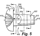
頭付きブランクの冷間成形は、本発明の位置実施形態に関連する完成したねじを最終的に形成するために使用されるものであり、これを図4に示す。このブランクは、典型的には3個の小葉型の断面を有するブランクであるが、それ以外の個数の小葉を用いることも明らかに考慮されている。形成用ダイキャビティ404を有する硬質のヘッダダイ402が示されている。成形プロセスは、典型的には、ほぼ円形の又は小葉型の断面を有する所定の大きさのワイヤ又はロッドの切断片がダイキャビティ内に配置されたときに開始される。多くの場合、異なる成形段階を表す3個又は4個以上の異なるダイキャビティが1ラインで使用され、その1つのダイキャビティから別のダイキャビティへとブランクが漸次移動されることになる。本例示の実施形態では、最終成形ダイ402が示されている。そのダイキャビティ404は、所望の完成したブランク形状と一致する大きさに形成された孔である。該ダイキャビティ404は、未完成のブランクが内部に打ち込まれて図示するような所望の完成したブランク405へと可塑的に変形される際にダイキャビティの変形が生じないよう十分な厚さ及び硬度を有する側壁を有している。勿論、ダイキャビティ404の横断面(図示せず)は、以下で詳述するように、所望のブランク断面(円形又は多小葉型の周辺)を画定するものである。
Cold forming of the headed blank is used to finally form the finished screw associated with the position embodiment of the present invention, as shown in FIG. This blank is typically a blank having three leaflet-shaped cross sections, but the use of other numbers of leaflets is clearly contemplated. A rigid header die 402 having a forming
ダイキャビティ404内の完成したブランク405の成形は、ラム又はパンチ406により加えられる複数回の打撃で生じることが多い。例示的なパンチ406は、典型的には強力な機械的なアクチュエータ(図示せず)により駆動され、ブランクを高圧で打撃してブランク頭と完成した内部のブランク形状とを同時に形成する。複数のダイキャビティを漸次用いる場合と同様に、ブランク405の成形時に複数の異なる形状のパンチを使用することが可能である。この場合、各パンチは、完成したブランク頭410の形状に漸進的に近くなっていく形状を有するものとなる。この実施形態では、ブランク頭410は、Phillips駆動構造412(断面で示す)を含む。しかし、該駆動構造は、あらゆる所望の形状とすることが可能であり、代替的に、(例えば)標準的な凹上の十字スロット、六葉型駆動凹部、又は六角ソケット凹部とすることが可能である。その他にも、ブランクは、あらゆる外部的又は内部的なレンチ係合用の頭駆動用形状を設けることが可能なものであり、又は適切かつ適当な機構を介してねじにトルクを伝達することを可能とする他のあらゆる機構を含むことが可能である。可動突き出しピン414を使用して、ブランクの先端を停止させ、及び完成したブランクを(後述する)ねじ山形成ダイへと導くチャネルその他の搬送手段へとイジェクトすることが可能である、ということに留意されたい。
Molding of the finished blank 405 within the
ダイキャビティ404は、本発明の様々な実施形態に従って少なくとも4つの別個の形状のブランク部分を生成する。冷間成形による完成した頭付きブランク405のそれらの部分を図5に示し、以下で詳述する。例示的な一実施形態によれば、かかる部分は、円錐ポイント(又は「エントリ」)部分502、本体部分504、及び頭410に隣接するテーパ部分506、及び頭自体を含む。
The
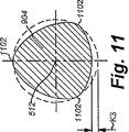
円錐ポイント部分502、本体部分504、及びテーパ部分506における全体的な断面が、図6、図7、及び図8にそれぞれ示されている。概して言えば、ねじブランクは、先端510から頭410へと連続的にテーパ付けされた形状を画定する。例示的なブランクの特徴となる3小葉型の断面形状が、図6及び図7の断面(それぞれ小葉602,702を参照)に一層明瞭に示されている。該小葉602,702は、軸512を中心とし、それぞれ同軸円606,706(仮想線で示す)内に位置する。小葉602,702間の「谷」領域は、(それぞれ)円外れ間隔K1,K2だけ間隔を置く。本書に記載するように「円外れ」が大きくなるほど値Kが大きくなる。これはまた、本発明の教示によれば、「小葉性」の度合いとも称することができる。
Overall cross sections at the
同様に、図8は、テーパ部分506の軸方向のほぼ中間点を横切る断面を示している。この軸512を中心とする断面は、本質的に円形であり、該部分に沿った円形の輪郭を表している。また図5を参照すると、テーパ部分506は、本体部分504から頭410の下側514に近づくにつれて外方へとテーパがついている。該テーパの増大の度合いは、形成されたねじ山の軸方向ピッチ(図14のピッチAPを参照)の約2倍以上であり、その軸方向長さは、好ましくは、形成されたねじ山の軸方向ピッチ(AP)の3.5倍である値WB以下である。
III. ねじ形成
図9及び図10は、完成したねじ(符号902で示す)を作製するためのブランク405上のねじ山の形成を詳細に示したものである。この実施形態では、ねじ902は、頭410の直ぐ下でブランクの軸に沿って平坦なロールフォーミングダイ908,910により係合される。これらのダイは、一方のダイプレート908が他方のダイプレート910に対して横方向(矢印1002)に移動される際に、3つの部分(502,504,506)の各々におけるブランク表面の可塑的な変形を生じさせるのに十分な圧力(矢印912)を加える。該ダイプレートの移動中に、該ダイプレート間の間隔は、互いに対面するダイ形成面間の等距離の中央線により示すように一定に維持される。ダイが、偏心した断面のブランクに係合するため、該ダイ908の動きにより、振動するブランクの転動が生じることになる。詳細には、転動するブランク/ねじの中心軸512は、中心線1004の上下に交互に延びる経路1008をたどる。しかし、ダイ間の距離が一定であるため、平坦なアンビルマイクロメータを使用した断面の測定値は、完成したねじの外周全体について一定の大きさを示す傾向を有するものとなる。
Similarly, FIG. 8 shows a cross section that crosses approximately the midpoint of the tapered
III. Thread Formation FIGS. 9 and 10 show in detail the formation of threads on the blank 405 to produce the finished screw (designated 902). In this embodiment, the
特に図9を参照すると、形成されたテーパ付き谷底部分906の領域におけるダイ908,910には、特徴的な外方テーパ920が設けられる。この外方テーパは、ブランクのテーパ部分に作用し、その結果として、本体部分904におけるねじ山の頂に対して比較的一定の外径(破線914参照)を維持するねじ山輪郭の頂を有するねじ山パターンを形成するが、破線916で示すような内径(各ねじ山輪郭の谷)は、頭410に向かって特徴的な円錐状の外方テーパを呈するものとなる。ブランクが転動する際に移動するダイ908,910の作用によって大きな部分に連続するテーパが形成される。更に、一連のブランク材料は、ダイの形状に基づいて、図9(及び後述する図15)に示す一層連続的な外観を呈する。この外方にテーパした形状は、従来技術において一般に見られた頭の近傍の望ましくない充填不足とは全く対照的なものである。
With particular reference to FIG. 9, the
ここで図11ないし図13に一層詳細に示す転動するねじ902の断面を参照する。図11を参照すると、本体部分904は、複数の小葉1102とその間に位置する「谷」との間の円外れ値K3を示している。
Reference is now made to the cross-section of the rolling
ねじ山が形成されたテーパ付き谷底部分906のうち本体904に隣接する部分を詳細に示す図12の断面は、小葉1202間の縮小された(しかし依然として大きな)円外れ値K4を示している。転動するダイは、先細りの増大に比例して(テーパが頭の下側514に近づくにつれて)低下した圧力を加えることが一般に理解されよう。したがって、頭の下側に比較的近い図13の断面では、比較的小さい円外れ値K5が示されている。この小さな(最小の)円外れ断面形状は、本説明の目的では「最近円断面」と称することができる。実施形態によっては、最近円断面は、本質的に円形とすることが可能である。このため、該用語は、かかる代替例も含むものとして解釈されるべきである。
The cross section of FIG. 12 detailing the portion of the threaded tapered
明らかに、上述のブランクの振動性の転動運動は、ロールフォーミングダイの影響下では、頭の下側に隣接するテーパの付いた円形の断面の最終的な形成に影響を与える傾向を有するものとなる。本書で用いるブランク及びねじ形成ダイの組み合わせは、クランプ結合領域に円形の断面を有するねじに伴う振動による緩みに対して向上した耐性を有する多小葉型ねじの有利なねじ山形成特性を有するねじを結果的に生じるものとなることもまた明らかである。この最近円断面は、部分的にはテーパ付き谷底部分の結果として得られ、該テーパ付き谷底部分は、その領域における形成圧力を有利に低下させるものである。
IV. 結合アセンブリ
図14に詳細に示すように、完成した転動によるねじ902は、第1の薄い被加工物1402と第2の固定材用の被加工物1404とからなるアセンブリを共に結合させる。頭410は、第1の被加工物1402に対して堅く圧縮される。図示のように2つ又は3つ以上の別個の螺旋コイル、スクロール、又はリードねじ山1406,1408がねじ902に形成されている。これらは、ねじシャフトに沿って同じ軸方向位置に配置された直径方向で対向するねじ山輪郭1406,1408によって表されている。上述のように、完成したねじは、任意の小葉型の断面領域(3,5,9,11その他の個数の小葉)からなるものである。テーパ付き谷底部分906は、固定材1404に係合し、該固定材1404を前後方向に押し出して(押し出し位置1405を参照)、該固定材1404とねじ山1406等との間に更なるねじ係合を提供することに留意されたい。該押し出しは、部分的にはテーパ付き谷底部分におけるねじ山の谷が頭に向かって外方へテーパしているために生じ、一方、ねじ山の頂は、少なくとも本体部分の隣接部分の頂とほぼ同じ直径を維持する(及び頭の近くの断面が一層完全な円形になる)。このため、ねじが薄い固定材1404内に締め付けられるにつれて、該固定材1404が、図示するように、テーパ付き谷底部分のねじ山の谷に対して、軸方向前方及び後方に移動する位置へと次第に圧縮されていく。
Obviously, the oscillatory rolling motion of the blank described above tends to affect the final formation of a tapered circular cross section adjacent to the underside of the head under the influence of a roll forming die. It becomes. The blank and thread forming die combination used in this document is a screw having the advantageous thread forming characteristics of a multi-leaflet screw that has improved resistance to vibration loosening associated with a screw having a circular cross-section in the clamp coupling area. It is also clear that it will result. This recent circular cross section is obtained in part as a result of a tapered valley bottom, which advantageously reduces the forming pressure in that region.
IV. Joining Assembly As shown in detail in FIG. 14, the finished rolling
繰り返しになるが、2つ又は3つ以上の対向するコイル又はリード手段の使用は、固定材の所与の断面に沿った複数の位置が固定されることを意味している。この固定は、最近円の断面と一層円外れの大きい断面との間のテーパ付き谷底部分の領域で達成され、これにより、振動その他の外力による緩みに対する耐性が向上する。完成したねじでは、ねじ山1406,1408等が、隣接するねじ山間の距離である軸方向ピッチAPを画定する。図5に関して上述したように、テーパ付き谷底部分の長さWBは、一実施形態では軸方向ピッチAPの少なくとも2倍である。別の例示的な実施形態では、テーパ付き谷底部分の長さWBは、軸方向ピッチAPの3.5倍以下となる。
Again, the use of two or more opposing coils or lead means means that a plurality of positions along a given cross-section of the fixture are fixed. This fixation is achieved in the region of the tapered valley bottom between the most recent circular cross-section and the more out-of-circular cross-section, thereby improving resistance to loosening due to vibrations and other external forces. In the finished screw,
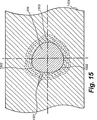
固定材1404の断面における力の分布を図15に示す。詳細には、固定材1404内に存在するねじのテーパ付き谷底部分906は、各小葉1502の付近に応力勾配の集中を呈する一連の応力線1501により分類される応力パターンを生成する。この実施形態では3つの小葉1502が示されていることに留意されたい。
FIG. 15 shows the force distribution in the cross section of the fixing
交互に生じる応力の弛緩領域と集中領域とにより、振動その他の外力に基づく固定材からのねじの緩みに対する機械的耐性が向上する。 The stress relaxation region and the concentration region that occur alternately improve the mechanical resistance against the loosening of the screw from the fixing member based on vibration or other external force.
上記では、本発明の特定の実施形態を詳細に説明したが、本発明の思想及び範囲から逸脱することなく様々な変更や追加を実施することが可能である。例えば、セルフタッピングねじ山の設計を変更することが可能であり、また代替的な実施形態において代替的なねじ山形成輪郭に置換することが可能である。同様に、連続する螺旋コイル又はねじ山の数等を広範に変更することが可能である。更に、ねじの材料及び硬度、並びに下方に位置するシート状の固定シート材の材料を変更することが可能である。したがって、必要な場合には、所定のタイプの特定の固定材と係合する際に加えられるトルクに(破損せずに)耐えることができるようねじ材料が処理される。かかる処理には、表面硬化及び/又は導入点硬化が含まれる。したがって、上記説明は、本発明の例示としてのみ捉えられるべきものを意味するものであって本発明の範囲を制限するものではない。 While specific embodiments of the invention have been described in detail above, various changes and additions can be made without departing from the spirit and scope of the invention. For example, the design of the self-tapping thread can be changed and can be replaced with an alternative threading profile in alternative embodiments. Similarly, the number of continuous helical coils or threads can be varied widely. Furthermore, it is possible to change the material and hardness of the screw, and the material of the sheet-like fixed sheet material located below. Thus, if necessary, the thread material is treated so that it can withstand (without breaking) the torque applied when engaging a particular type of fixed material. Such treatment includes surface curing and / or introductory point curing. Therefore, the above description is meant only to be taken as an example of the present invention and does not limit the scope of the present invention.
Claims (12)
頭(302)に直ぐ隣接して配置されたテーパ付き谷底部分(304)であって、前記頭(302)と前記本体部分(306)との間にあり、及び変動する断面を画定し、該変動する断面が、前記頭(302)に隣接する最近円断面から前記小葉型の本体部分(306)に隣接する多小葉型の断面まで変動する、テーパ付き谷底部分(304)を特徴とし、
前記複数のリードねじ山(312)が、前記円錐ポイント部分(502)、前記本体部分(306)、及び前記テーパ付き谷底部分(304)に沿って配置され、及び一定のねじ山輪郭を有しており、前記中心軸(512)から各リードねじ山(312)の頂まで測定した半径方向距離が、前記テーパ付き谷底部分(304)と該テーパ付き谷底部分(304)に隣接する前記本体部分(306)の少なくとも一部とに沿って一定に維持され、
前記本体部分(306)、前記円錐ポイント部分(502)、及び前記テーパ付き谷底部分(304)の各々が、前記頭(302)から前記中心軸(512)に沿って前記第1の被加工物(1402)及び前記第2の被加工物(1404)を通って延びるよう構成され、前記リードねじ山(312)が、前記第2の被加工物(1404)と係合して、前記テーパ付き谷底部分(304)が該第2の被加工物(1404)に係合した状態で該第2の被加工物(1404)を前記第1の被加工物(1402)及び頭(302)に対して強制的に圧縮させるようになっている、ねじ(300)。A screw (300) for joining a thin workpiece (1402, 1404), wherein the screw (300) is formed around a predetermined central axis (512) and a plurality of lead threads (312) and The head (302) has a first workpiece (1402) placed on the second workpiece (1404), and the second workpiece (1404) has a thin fixing material. And wherein the screw (300) includes a body portion (306) defining a multilobal cross section and a conical point portion (502) defining a multilobal cross section;
A tapered valley bottom portion (304) disposed immediately adjacent to the head (302), between the head (302) and the body portion (306) and defining a varying cross section; Characterized by a tapered valley bottom portion (304), wherein the varying cross-section varies from a closest circular cross-section adjacent to the head (302) to a multi-leaflet cross-section adjacent to the leaflet-shaped body portion (306);
The plurality of lead threads (312) are disposed along the conical point portion (502), the body portion (306), and the tapered valley bottom portion (304) and have a constant thread profile. A radial distance measured from the central axis (512) to the top of each lead screw thread (312) is the tapered valley bottom portion (304) and the main body portion adjacent to the tapered valley bottom portion (304). Along with at least a portion of (306),
Each of the body portion (306), the conical point portion (502), and the tapered valley bottom portion (304) extends from the head (302) along the central axis (512) to the first workpiece. (1402) and the second workpiece (1404), and the lead thread (312) engages the second workpiece (1404) and is tapered. With the valley bottom portion (304) engaged with the second workpiece (1404), the second workpiece (1404) is moved relative to the first workpiece (1402) and the head (302). Screw (300), which is designed to be forced to compress.
所定の中心軸(512)の周りに形成されたねじ山(312)及び頭(302)を有するねじ(300)を使用して少なくとも第1の薄い被加工物(1402)と第2の薄い被加工物(1404)とを結合させ、該ねじ(300)が、多小葉型のねじ山形成断面を画定する本体部分(306)と、前記頭(302)に直ぐ隣接して配置されたテーパ付き谷底部分(304)であって、前記頭(302)と前記本体部分(306)との間にあり、及び該頭(302)に隣接する最近円断面から前記本体部分(306)に隣接する最大の小葉型を有する多小葉型の断面まで変動する断面を画定する、テーパ付き谷底部分(304)と、多小葉型のねじ山形成断面を画定する円錐ポイント部分(502)と、前記ねじ本体(306)及び前記テーパ付き谷底部分(304)に沿って配置された一定のねじ山輪郭(1406,1408)を有するリードねじ山(1406,1408)とを含み、前記回転軸(512)から各ねじ山の頂までの一定の半径方向距離が、前記テーパ付き谷底部分(304)と該テーパ付き谷底部分(304)に隣接する前記本体部分(306)の少なくとも一部との両方に沿って維持されており、該方法が、
ねじ(300)を回転させると共にその回転軸(512)に沿って前記第1の被加工物(1402)及び前記第2の被加工物(1404)の方向に圧力を加え、前記リードねじ山(1406,1408)が、前記テーパ付き谷底部分(304)において前記第2の被加工物(1404)と係合して、該第2の被加工物(1404)が前記第1の被加工物(1402)及び前記頭(302)を強制的に圧縮し、
前記第1の薄い被加工物(1402)が前記テーパ付き谷底部分(304)により画定される多小葉型の断面間で弛緩する際に外力による緩みに対する耐性を提供する、
ねじ(300)の使用方法。Use of the screw (300) according to any one of claims 1 to 4,
A screw (300) having a thread (312) and a head (302) formed about a predetermined central axis (512) is used to at least a first thin workpiece (1402) and a second thin workpiece. A workpiece (1404) coupled to the body (306) defining a multi-leaflet threaded cross-section and a tapered portion disposed immediately adjacent to the head (302) A valley bottom portion (304) between the head (302) and the body portion (306), and from a nearest circular cross-section adjacent to the head (302) adjacent to the body portion (306) A tapered valley bottom portion (304) defining a cross-section varying to a multi-leaflet cross-section having a leaflet shape, a conical point portion (502) defining a multi-leaflet thread-forming cross-section, and the screw body ( 306) and a lead thread (1406, 1408) having a constant thread profile (1406, 1408) disposed along the tapered valley bottom portion (304), each thread from the rotational axis (512). A constant radial distance to the top of the mountain is maintained along both the tapered valley bottom portion (304) and at least a portion of the body portion (306) adjacent to the tapered valley bottom portion (304). And the method is
The screw (300) is rotated and pressure is applied in the direction of the first work piece (1402) and the second work piece (1404) along the rotation axis (512) so that the lead thread ( 1406, 1408) engage with the second workpiece (1404) at the tapered valley bottom portion (304), and the second workpiece (1404) becomes the first workpiece (1404). 1402) and the head (302) are forcibly compressed,
Providing resistance to loosening due to external forces when the first thin workpiece (1402) relaxes between multi-leaflet sections defined by the tapered valley bottom portion (304);
How to use the screw (300).
ねじ山をロールフォーミングするための1つ又は2つ以上の直線状の溝を有する第1のダイ(908)であって、その一端に向かう外方テーパを有し、該外方テーパが、ねじ頭に直ぐ隣接するねじブランクのテーパ付き谷底部分のねじ山のロールフォーミングを可能とするよう形成されている、第1のダイ(908)と、
該第1のダイ(908)と対面する第2のダイ(910)であって、該第1のダイが、該第2のダイ(910)との間に一定の間隔を置いて該第2のダイ(910)に対して移動可能であり、該第2のダイ(910)が、ねじ山をロールフォーミングするための1つ又は2つ以上の直線状の溝を有しており、及びその一端に向かう外方テーパを有しており、該外方テーパが、前記ねじブランクの前記テーパ付き谷底部分のねじ山のロールフォーミングを可能とするよう形成されている、第2のダイ(910)と
を含み、本体部分上のねじ山の外径と実質的に同じ外径のねじ山が、前記テーパ付き谷底部分に設けられ、
前記第1のダイ(908)の前記外方テーパ及び前記第2のダイ(910)の外方テーパが、それぞれ、前記テーパ付き谷底部分上にねじ山を形成するよう構成されており、該テーパ付き谷底部分が、前記頭へと向かう最近円部分から前記本体部分に隣接する最大小葉部分へと変化するものである、
一対のロールフォーミングダイ。A pair of roll forming dies for forming a screw thread on a multi-leaflet type screw blank,
A first die (908) having one or more linear grooves for roll forming a screw thread, having an outward taper toward one end thereof, the outer taper being a screw A first die (908) configured to allow roll forming of a thread in a tapered valley bottom portion of a screw blank immediately adjacent to the head;
A second die (910) facing the first die (908), the first die being spaced apart from the second die (910) by the second die (910); The second die (910) has one or more linear grooves for roll forming the threads, and A second die (910) having an outward taper toward one end, the outward taper being configured to allow roll forming of a thread of the tapered valley bottom portion of the screw blank. wherein the door outer diameter substantially the thread of the same outer diameter of the threads on the body portion, provided in the tapered trough bottom,
The outer taper of the first die (908) and the outer taper of the second die (910) are each configured to form a thread on the tapered valley bottom portion, the taper The attached valley bottom part changes from the nearest circular part toward the head to the largest leaflet part adjacent to the main body part,
A pair of roll forming dies.
実質的に直線状のブランクを受容する成形用ダイキャビティ(404)であって、軸を通る断面を有し、及び、
i) 前記ブランクの頭に直ぐ隣接して円形の断面を画定し、及びそこから離隔して本体部分へと延びる、テーパ部分と、
ii) 多小葉型の断面を画定する本体部分と、
iii) 該本体部分から延び、及び多小葉型の断面を画定する、円錐ポイント部分と
を画定するダイ内壁を含む、成形用ダイキャビティ(404)を含む、
請求項6ないし請求項8の何れか一項に記載の一対のロールフォーミングダイ。The blank is formed from a metal shaft by a header die (402), the header die (402)
A molding die cavity (404) for receiving a substantially straight blank, having a cross-section through an axis; and
i) a tapered portion defining a circular cross-section immediately adjacent to the head of the blank and extending away from it to the body portion;
ii) a body portion defining a multi-leaflet cross section;
iii) includes a mold die cavity (404) that includes a die inner wall defining a conical point portion extending from the body portion and defining a multi-leaflet cross-section;
A pair of roll forming dies according to any one of claims 6 to 8 .
一対のダイ間に小葉型の本体部分を有する頭付きブランクを挿入し、該一対のダイの各々の一方の側に設けられた一組の直線状の溝及びテーパ領域が、前記頭付きブランクの頭に直ぐ隣接してその円形のテーパ部分上に配置されるよう構成されており、
前記一対のダイから前記頭付きブランクに圧縮力を加え、
前記一対のダイの一方を直線方向に移動させることにより前記頭付きブランクを該一対のダイ間で転動させ、これにより該ブランクの中心軸が前記ダイ間の空間の中心線に対して振動する経路を画定し、該ダイが前記頭付きブランクを可塑的に変形させることにより前記ねじ本体と前記テーパ部分上のテーパ付き谷底部分との上に一組のねじ山を形成し、
前記本体部分上のねじ山の外径と実質的に同じ外径のねじ山が前記テーパ付き谷底部分に設けられ、
前記頭付きブランクの前記テーパ付き谷底部分に沿って可変断面を形成し、該可変断面が、前記頭に隣接する最近円断面から前記本体に隣接する最大小葉型断面まで変動するものである、
ねじの作成方法。A method for creating a thread for coupling the thin workpiece using a roll forming die according to any one of claims 6 to 9,
A headed blank having a leaflet-shaped main body portion is inserted between a pair of dies, and a pair of linear grooves and a tapered region provided on one side of each of the pair of dies are provided on the headed blank. It is configured to be placed on its circular taper immediately adjacent to the head,
Apply compressive force to the headed blank from the pair of dies,
The headed blank is rolled between the pair of dies by moving one of the pair of dies in a linear direction, whereby the central axis of the blank vibrates with respect to the center line of the space between the dies. Defining a path, the die plastically deforming the headed blank to form a set of threads on the screw body and a tapered valley bottom portion on the tapered portion;
A thread having an outer diameter substantially the same as the outer diameter of the thread on the body portion is provided in the tapered valley bottom portion;
Forming a variable cross section along the tapered valley bottom portion of the headed blank, the variable cross section varying from a nearest circular cross section adjacent to the head to a maximum leaflet cross section adjacent to the body;
How to create a screw.
実質的に直線状のブランクを受容する成形用ダイキャビティであって、軸を通る断面を有し、及び、
i) 前記ブランクの頭に近接して円形の断面を画定し、及びそこから離隔して本体部分へと延びる、テーパ部分と、
ii) 多小葉型の断面を画定する本体部分と、
iii) 該本体部分から延び、及び多小葉型の断面を画定する、円錐ポイント部分と
を画定するダイ内壁を含む、成形用ダイキャビティを含むものである、
請求項10又は請求項11の何れか一項に記載の方法。Forming a headed blank by applying a header die to the metal shaft, the header die comprising:
A molding die cavity for receiving a substantially straight blank, having a cross section through an axis; and
i) a tapered portion defining a circular cross-section proximate to the head of the blank and extending away from it to the body portion;
ii) a body portion defining a multi-leaflet cross section;
iii) includes a molding die cavity including a die inner wall defining a conical point portion extending from the body portion and defining a multi-leaflet cross section.
12. A method according to any one of claims 10 or 11 .
Applications Claiming Priority (2)
| Application Number | Priority Date | Filing Date | Title |
|---|---|---|---|
| US09/952,157 US6494656B1 (en) | 2001-09-13 | 2001-09-13 | Self-tapping screw, blank and method for joining thin workpieces and production method for the same |
| PCT/EP2002/008960 WO2003023239A1 (en) | 2001-09-13 | 2002-08-09 | Self-tapping screw, blank, method and dies for making the same and method for joining thin workpieces |
Publications (3)
| Publication Number | Publication Date |
|---|---|
| JP2005502835A JP2005502835A (en) | 2005-01-27 |
| JP2005502835A5 JP2005502835A5 (en) | 2006-01-05 |
| JP4480395B2 true JP4480395B2 (en) | 2010-06-16 |
Family
ID=25492634
Family Applications (1)
| Application Number | Title | Priority Date | Filing Date |
|---|---|---|---|
| JP2003527277A Expired - Lifetime JP4480395B2 (en) | 2001-09-13 | 2002-08-09 | Self-tapping screws, blanks, methods, and dies and methods for making them for joining thin workpieces |
Country Status (11)
| Country | Link |
|---|---|
| US (2) | US6494656B1 (en) |
| EP (1) | EP1425514B1 (en) |
| JP (1) | JP4480395B2 (en) |
| KR (1) | KR100959296B1 (en) |
| CN (1) | CN1306174C (en) |
| AT (1) | ATE328210T1 (en) |
| CA (1) | CA2446242C (en) |
| DE (1) | DE60211920T2 (en) |
| ES (1) | ES2269752T3 (en) |
| SG (1) | SG125144A1 (en) |
| WO (1) | WO2003023239A1 (en) |
Cited By (1)
| Publication number | Priority date | Publication date | Assignee | Title |
|---|---|---|---|---|
| US9267528B2 (en) | 2012-06-26 | 2016-02-23 | Topura Co., Ltd. | Tapping screw |
Families Citing this family (33)
| Publication number | Priority date | Publication date | Assignee | Title |
|---|---|---|---|---|
| GB9926968D0 (en) * | 1999-11-15 | 2000-01-12 | Univ London | Treatment of neurological disorders |
| US6799483B2 (en) * | 2001-05-15 | 2004-10-05 | Patrick Andreas Petri | Method and mechanism for converting vibration induced rotation into translational motion |
| US20030210970A1 (en) * | 2002-03-26 | 2003-11-13 | Bechtel Frank W. | Radius gimlet point anti-stripout screw |
| US6940209B2 (en) * | 2003-09-08 | 2005-09-06 | New Scale Technologies | Ultrasonic lead screw motor |
| US7170214B2 (en) | 2003-09-08 | 2007-01-30 | New Scale Technologies, Inc. | Mechanism comprised of ultrasonic lead screw motor |
| US7309943B2 (en) * | 2003-09-08 | 2007-12-18 | New Scale Technologies, Inc. | Mechanism comprised of ultrasonic lead screw motor |
| DE102004034246B4 (en) * | 2004-07-15 | 2008-04-24 | Sfs Intec Holding Ag | screw |
| US20060090325A1 (en) * | 2004-11-02 | 2006-05-04 | Bernard Jeremy R | Vehicle powertrain joints comprising self-tapping fasteners |
| WO2007048267A1 (en) * | 2005-10-28 | 2007-05-03 | Medartis, Ag | Thread-forming screw |
| DE102008033509A1 (en) * | 2008-07-07 | 2010-01-14 | Arnold Umformtechnik Gmbh & Co. Kg | screw |
| DE102009002078A1 (en) * | 2009-04-01 | 2010-10-07 | Ford Global Technologies, LLC, Dearborn | Connecting device for connecting mudguard with e.g. door strut, has screw whose external thread is inserted via internal thread of opening in non-cutting deformation state, where screw exhibits screw head and threaded shaft |
| DE102010000702A1 (en) * | 2010-01-06 | 2011-07-07 | Arnold Umformtechnik GmbH & Co. KG, 74670 | Thread forming screw and its use |
| US8529178B2 (en) | 2010-02-19 | 2013-09-10 | Nucor Corporation | Weldless building structures |
| US9004835B2 (en) | 2010-02-19 | 2015-04-14 | Nucor Corporation | Weldless building structures |
| IT1403796B1 (en) * | 2011-01-12 | 2013-10-31 | Savio Spa | "FASTENING SYSTEM FOR ACCESSORIES ON METAL MATERIAL FRAMES FOR DOORS, WINDOWS AND THE LIKE" |
| JP2012182378A (en) * | 2011-03-02 | 2012-09-20 | Tokyo Electron Ltd | Positioning mechanism and inspection device of probe card |
| PL2657547T3 (en) * | 2012-04-24 | 2014-08-29 | Nedschroef Fraulautern Gmbh | Screw |
| US9016994B2 (en) * | 2013-02-11 | 2015-04-28 | James Michael Platt | Threaded fastener |
| DE102013106758B4 (en) | 2013-06-27 | 2022-06-09 | Aesculap Aktiengesellschaft | Out-of-round pedicle screw |
| TWI555920B (en) * | 2014-07-17 | 2016-11-01 | Screw structure improvement | |
| US9488210B2 (en) * | 2014-09-30 | 2016-11-08 | Ford Global Technologies, Llc | Flow drill screw assembly and method |
| JP5770399B1 (en) * | 2015-03-02 | 2015-08-26 | クラウン精密工業株式会社 | Self-tapping screw and manufacturing method thereof |
| US10125805B2 (en) * | 2015-04-21 | 2018-11-13 | Sungwoo Hitech Co., Ltd | Rivet screw drill |
| CN105134731B (en) * | 2015-09-25 | 2017-04-12 | 安徽工程大学 | Threadless plastic self-tapping screw tightly fixed on metal thin-wall casing |
| DE102015222281A1 (en) * | 2015-11-12 | 2017-05-18 | Arnold Umformtechnik Gmbh & Co. Kg | Thread forming screw |
| WO2017102290A1 (en) * | 2015-12-15 | 2017-06-22 | Electrolux Appliances Aktiebolag | Cooking oven |
| CA3211072A1 (en) | 2016-05-02 | 2017-11-02 | Asia Fastening (Us), Inc. | Double threaded standoff fastener |
| DE102016211444A1 (en) * | 2016-06-27 | 2017-12-28 | Arnold Umformtechnik Gmbh & Co. Kg | Connecting element and method for connecting at least two workpieces |
| CN107816483A (en) * | 2017-02-05 | 2018-03-20 | 超捷紧固系统(上海)股份有限公司 | Metric system self tapping backing-up screw and its manufacture method |
| TWI622710B (en) * | 2017-05-02 | 2018-05-01 | 徐敏豪 | Screw for a thin iron plate |
| US11686337B2 (en) | 2018-12-31 | 2023-06-27 | Robert E. Stewart | Faceted lobular threads |
| IT201900022686A1 (en) * | 2019-12-02 | 2021-06-02 | Wm System Srl | SCREW AND METHOD OF ASSEMBLY BY MEANS OF THE SCREW |
| WO2023077011A1 (en) * | 2021-10-27 | 2023-05-04 | Semblex Corporation | Torque reducing flow drilling fastener for thick materials and method of using such fastener |
Family Cites Families (41)
| Publication number | Priority date | Publication date | Assignee | Title |
|---|---|---|---|---|
| US23409A (en) | 1859-03-29 | Improved manufacture of wood-screws | ||
| US1872166A (en) | 1930-11-06 | 1932-08-16 | Muhlig Ludwik | Screw |
| US3918345A (en) * | 1961-06-27 | 1975-11-11 | Res Eng & Mfg | Thread forming fasteners |
| GB1022355A (en) * | 1962-08-31 | 1966-03-09 | Res Eng & Mfg | Self-tapping screw with lobular work-entering end and methods for manufacturing same |
| US3180126A (en) * | 1962-11-14 | 1965-04-27 | Textron Ind Inc | Self-tapping screw and method of manufacture |
| US3978760A (en) * | 1970-01-19 | 1976-09-07 | Research Engineering & Manufacturing, Inc. | Self-thread forming threaded fasteners and blanks for making same |
| US3945272A (en) * | 1970-01-30 | 1976-03-23 | Nl Industries Inc. | Thread-rolling method, thread-rolling dies, and method of manufacturing the dies |
| US3661046A (en) | 1970-11-09 | 1972-05-09 | Illinois Tool Works | Combination screw |
| US3812639A (en) | 1973-03-26 | 1974-05-28 | Illinois Tool Works | Locking and strip-resistant fastener |
| US3949641A (en) | 1974-11-04 | 1976-04-13 | The Steel Company Of Canada, Limited | Self-drilling screw |
| GB1537701A (en) | 1976-01-09 | 1979-01-04 | Avdel Ltd | Drills and self-drilling screws |
| US4034586A (en) * | 1976-05-24 | 1977-07-12 | Colt Industries Operating Corporation | Thread rolling die and method of thread rolling |
| US4310272A (en) * | 1980-01-18 | 1982-01-12 | Textron Inc. | Threaded fastener and structural joint attained therewith |
| US4368552A (en) | 1980-11-04 | 1983-01-18 | Crown Screw Corporation | Method of making self tapping thread forming screw |
| JPS589513U (en) * | 1981-07-14 | 1983-01-21 | 株式会社青山製作所 | Tatsu pin screw |
| DE3272798D1 (en) * | 1982-02-18 | 1986-10-02 | Conti Fasteners Ag | Screw |
| DE3332570A1 (en) * | 1983-09-09 | 1985-03-28 | Friedr. Boesner GmbH, 5450 Neuwied | METHOD FOR PRODUCING SELF-SHAPING AND SELF-LOCKING SCREWS WITH ADDITIONAL SEALING AND / OR SETTING PROPERTIES |
| US5252016A (en) | 1989-11-13 | 1993-10-12 | Isolink Inc. | Fixing element for low strength materials |
| US5061135A (en) | 1990-08-28 | 1991-10-29 | Research Engineering & Manufacturing, Inc. | Thread tapping screw |
| US5356253A (en) * | 1992-04-29 | 1994-10-18 | Whitesell Neil L | Sheet metal screw |
| US5183359A (en) | 1992-05-12 | 1993-02-02 | Illinois Tool Works Inc. | Rotary fastener with anti-strip-out nibs |
| CA2125357C (en) | 1993-06-09 | 1999-01-12 | David James Roberts | Self-drilling screw |
| US5456685A (en) | 1994-02-14 | 1995-10-10 | Smith & Nephew Dyonics, Inc. | Interference screw having a tapered back root |
| US5518352A (en) | 1994-10-17 | 1996-05-21 | Lieggi; Martin | Relief screw |
| CN2215621Y (en) * | 1994-12-22 | 1995-12-20 | 胡来忠 | Iron nail with teeth |
| JPH08226424A (en) * | 1995-02-18 | 1996-09-03 | Terufumi Nojigawa | Tapping screw and manufacture thereof |
| US5599149A (en) | 1995-02-28 | 1997-02-04 | Anchor Bolt And Screw Company | Self-tapping floor screw |
| JP3046746B2 (en) * | 1995-06-14 | 2000-05-29 | ミネベア株式会社 | Screw and screw manufacturing method |
| JP3050789B2 (en) * | 1996-01-08 | 2000-06-12 | 株式会社青山製作所 | Tapping screw |
| US6319270B1 (en) | 1996-08-05 | 2001-11-20 | Arthrex, Inc. | Headed bioabsorbable tissue anchor |
| US5722808A (en) | 1996-09-11 | 1998-03-03 | Conti Fasteners Ag | Threaded fastener system |
| KR100276352B1 (en) * | 1996-11-29 | 2000-12-15 | 하시모토 히사오 | Driving screw |
| CN1045814C (en) * | 1997-01-21 | 1999-10-20 | 陈河田 | Screw with multiple different lead screw tooth at pointed cone |
| JP3934165B2 (en) | 1997-07-29 | 2007-06-20 | エヨト フェルビンドゥングステヒニク ゲーエムベーハー ウント ツェーオー カーゲー | Screw with tapping screw |
| JP3020904B2 (en) * | 1997-11-06 | 2000-03-15 | クラウン精密工業株式会社 | Self tapping screw |
| US5909992A (en) | 1998-07-02 | 1999-06-08 | Wu; Tsan-Hsing | Self-tapping screw for fastening a metal corrugated board |
| US5921735A (en) * | 1998-08-19 | 1999-07-13 | Phillips Screw Company | Lobular fastener with rectilinear pitch profile |
| DE19857311A1 (en) * | 1998-12-11 | 2000-06-15 | Ejot Verbindungstech Gmbh & Co | Self-tapping screw |
| US6089806A (en) | 1999-01-25 | 2000-07-18 | Conti Fasteners | Blank for self-tapping fastener |
| US6045312A (en) * | 1999-03-17 | 2000-04-04 | Illinois Tool Works Inc. | Fastener having primary and secondary threads |
| JP4294802B2 (en) * | 1999-07-30 | 2009-07-15 | 日本パワーファスニング株式会社 | Drill screw with washer for thin plate fastening |
-
2001
- 2001-09-13 US US09/952,157 patent/US6494656B1/en not_active Expired - Lifetime
-
2002
- 2002-08-09 KR KR1020047003648A patent/KR100959296B1/en active IP Right Grant
- 2002-08-09 ES ES02758456T patent/ES2269752T3/en not_active Expired - Lifetime
- 2002-08-09 WO PCT/EP2002/008960 patent/WO2003023239A1/en active IP Right Grant
- 2002-08-09 JP JP2003527277A patent/JP4480395B2/en not_active Expired - Lifetime
- 2002-08-09 CN CNB02811602XA patent/CN1306174C/en not_active Expired - Lifetime
- 2002-08-09 AT AT02758456T patent/ATE328210T1/en not_active IP Right Cessation
- 2002-08-09 DE DE60211920T patent/DE60211920T2/en not_active Expired - Lifetime
- 2002-08-09 CA CA2446242A patent/CA2446242C/en not_active Expired - Lifetime
- 2002-08-09 SG SG200500999A patent/SG125144A1/en unknown
- 2002-08-09 EP EP02758456A patent/EP1425514B1/en not_active Expired - Lifetime
- 2002-10-03 US US10/264,195 patent/US6712708B2/en not_active Expired - Lifetime
Cited By (1)
| Publication number | Priority date | Publication date | Assignee | Title |
|---|---|---|---|---|
| US9267528B2 (en) | 2012-06-26 | 2016-02-23 | Topura Co., Ltd. | Tapping screw |
Also Published As
| Publication number | Publication date |
|---|---|
| DE60211920T2 (en) | 2006-10-19 |
| WO2003023239A1 (en) | 2003-03-20 |
| KR100959296B1 (en) | 2010-05-26 |
| CA2446242A1 (en) | 2003-03-20 |
| CN1306174C (en) | 2007-03-21 |
| DE60211920D1 (en) | 2006-07-06 |
| ES2269752T3 (en) | 2007-04-01 |
| SG125144A1 (en) | 2006-09-29 |
| CN1527908A (en) | 2004-09-08 |
| EP1425514A1 (en) | 2004-06-09 |
| JP2005502835A (en) | 2005-01-27 |
| CA2446242C (en) | 2010-10-26 |
| ATE328210T1 (en) | 2006-06-15 |
| US6712708B2 (en) | 2004-03-30 |
| EP1425514B1 (en) | 2006-05-31 |
| US6494656B1 (en) | 2002-12-17 |
| US20030049095A1 (en) | 2003-03-13 |
| KR20040039350A (en) | 2004-05-10 |
Similar Documents
| Publication | Publication Date | Title |
|---|---|---|
| JP4480395B2 (en) | Self-tapping screws, blanks, methods, and dies and methods for making them for joining thin workpieces | |
| US6089806A (en) | Blank for self-tapping fastener | |
| US3978760A (en) | Self-thread forming threaded fasteners and blanks for making same | |
| US3878759A (en) | Bi-lobular self-thread forming fastener | |
| CN100416114C (en) | Tapping assist fastening element and method | |
| JP2005502835A5 (en) | ||
| US3530760A (en) | Thread-forming screw | |
| US3935785A (en) | Thread swaging screw | |
| US3875780A (en) | Method of making a thread forming screw | |
| US3996834A (en) | Fastening element | |
| JPH0663531B2 (en) | Star fastener improvements | |
| JP2004504944A (en) | Lightweight screw fasteners and thread rolling dies | |
| JPH0646044B2 (en) | Asymmetric thread forming screw and manufacturing method thereof | |
| US3218905A (en) | Self-tapping or thread-forming screw | |
| CA2077733C (en) | Thread forming method and apparatus | |
| EP1270963B1 (en) | Fastener | |
| CN104963927A (en) | Flanging and riveting self-locking nut and machining method thereof | |
| US5182937A (en) | Seam-free thread rolling dies | |
| US6135892A (en) | Method of forming a short point anti-cross threading member | |
| JPS6025213B2 (en) | Method and tools for manufacturing elastic screws with a helical cavity closed inside the shape of a thread | |
| TW202144099A (en) | Method for manufacturing a profiled rod | |
| TW201447119A (en) | Method for producing screws and concrete screw | |
| RU30639U1 (en) | Thread-rolling fastener, tool for its manufacture | |
| TWI224655B (en) | Clinch-type blind nut | |
| GB1562385A (en) | Thread forming members |
Legal Events
| Date | Code | Title | Description |
|---|---|---|---|
| A521 | Request for written amendment filed |
Free format text: JAPANESE INTERMEDIATE CODE: A523 Effective date: 20050808 |
|
| A621 | Written request for application examination |
Free format text: JAPANESE INTERMEDIATE CODE: A621 Effective date: 20050808 |
|
| A131 | Notification of reasons for refusal |
Free format text: JAPANESE INTERMEDIATE CODE: A131 Effective date: 20080729 |
|
| A601 | Written request for extension of time |
Free format text: JAPANESE INTERMEDIATE CODE: A601 Effective date: 20081028 |
|
| A602 | Written permission of extension of time |
Free format text: JAPANESE INTERMEDIATE CODE: A602 Effective date: 20081105 |
|
| A521 | Request for written amendment filed |
Free format text: JAPANESE INTERMEDIATE CODE: A523 Effective date: 20090113 |
|
| A131 | Notification of reasons for refusal |
Free format text: JAPANESE INTERMEDIATE CODE: A131 Effective date: 20090303 |
|
| A601 | Written request for extension of time |
Free format text: JAPANESE INTERMEDIATE CODE: A601 Effective date: 20090603 |
|
| A602 | Written permission of extension of time |
Free format text: JAPANESE INTERMEDIATE CODE: A602 Effective date: 20090610 |
|
| A521 | Request for written amendment filed |
Free format text: JAPANESE INTERMEDIATE CODE: A523 Effective date: 20090723 |
|
| A131 | Notification of reasons for refusal |
Free format text: JAPANESE INTERMEDIATE CODE: A131 Effective date: 20090929 |
|
| A521 | Request for written amendment filed |
Free format text: JAPANESE INTERMEDIATE CODE: A523 Effective date: 20091224 |
|
| TRDD | Decision of grant or rejection written | ||
| A01 | Written decision to grant a patent or to grant a registration (utility model) |
Free format text: JAPANESE INTERMEDIATE CODE: A01 Effective date: 20100302 |
|
| A01 | Written decision to grant a patent or to grant a registration (utility model) |
Free format text: JAPANESE INTERMEDIATE CODE: A01 |
|
| A61 | First payment of annual fees (during grant procedure) |
Free format text: JAPANESE INTERMEDIATE CODE: A61 Effective date: 20100316 |
|
| FPAY | Renewal fee payment (event date is renewal date of database) |
Free format text: PAYMENT UNTIL: 20130326 Year of fee payment: 3 |
|
| R150 | Certificate of patent or registration of utility model |
Ref document number: 4480395 Country of ref document: JP Free format text: JAPANESE INTERMEDIATE CODE: R150 Free format text: JAPANESE INTERMEDIATE CODE: R150 |
|
| FPAY | Renewal fee payment (event date is renewal date of database) |
Free format text: PAYMENT UNTIL: 20130326 Year of fee payment: 3 |
|
| FPAY | Renewal fee payment (event date is renewal date of database) |
Free format text: PAYMENT UNTIL: 20140326 Year of fee payment: 4 |
|
| R250 | Receipt of annual fees |
Free format text: JAPANESE INTERMEDIATE CODE: R250 |
|
| R250 | Receipt of annual fees |
Free format text: JAPANESE INTERMEDIATE CODE: R250 |
|
| R250 | Receipt of annual fees |
Free format text: JAPANESE INTERMEDIATE CODE: R250 |
|
| R250 | Receipt of annual fees |
Free format text: JAPANESE INTERMEDIATE CODE: R250 |
|
| R250 | Receipt of annual fees |
Free format text: JAPANESE INTERMEDIATE CODE: R250 |
|
| R250 | Receipt of annual fees |
Free format text: JAPANESE INTERMEDIATE CODE: R250 |
|
| R250 | Receipt of annual fees |
Free format text: JAPANESE INTERMEDIATE CODE: R250 |
|
| R250 | Receipt of annual fees |
Free format text: JAPANESE INTERMEDIATE CODE: R250 |
|
| R250 | Receipt of annual fees |
Free format text: JAPANESE INTERMEDIATE CODE: R250 |
|
| R250 | Receipt of annual fees |
Free format text: JAPANESE INTERMEDIATE CODE: R250 |
|
| EXPY | Cancellation because of completion of term |