JP4420998B2 - Game machine - Google Patents
Game machine Download PDFInfo
- Publication number
- JP4420998B2 JP4420998B2 JP04918699A JP4918699A JP4420998B2 JP 4420998 B2 JP4420998 B2 JP 4420998B2 JP 04918699 A JP04918699 A JP 04918699A JP 4918699 A JP4918699 A JP 4918699A JP 4420998 B2 JP4420998 B2 JP 4420998B2
- Authority
- JP
- Japan
- Prior art keywords
- state
- parameter
- game
- value
- address
- Prior art date
- Legal status (The legal status is an assumption and is not a legal conclusion. Google has not performed a legal analysis and makes no representation as to the accuracy of the status listed.)
- Expired - Fee Related
Links
Images


Description
【0001】
【発明の属する技術分野】
本発明は、パチンコ遊技機やコイン遊技機等の遊技機に関し、特に、表示状態が変化可能な可変表示装置を含み、可変表示装置における表示結果があらかじめ定められた特定の表示態様となった場合に所定の遊技価値が付与可能となる遊技機に関する。
【0002】
【従来の技術】
遊技機として、表示状態が変化可能な可変表示部を有する可変表示装置が設けられ、可変表示部の表示結果があらかじめ定められた特定の表示態様となった場合に遊技者に有利となる大当り遊技状態に移行するように構成されたものがある。可変表示装置には複数の可変表示部があり、通常、複数の可変表示部の表示結果を時期を異ならせて表示するように構成されている。可変表示部には、例えば、特別図柄が可変表示される。
【0003】
可変表示部の表示結果があらかじめ定められた特定の表示態様の組合せとなることを、通常、「大当り」という。なお、遊技価値とは、遊技機の遊技領域に設けられた可変入賞球装置の状態が打球が入賞しやすい遊技者にとって有利な状態になることや、遊技者にとって有利な状態となるための権利を発生させたりすることである。
【0004】
大当りが発生すると、例えば、大入賞口が所定回数開放して打球が入賞しやすい大当り遊技状態に移行する。そして、各開放期間において、所定個(例えば10個)の大入賞口への入賞があると大入賞口は閉成する。そして、大入賞口の開放回数は、所定回数(例えば16ラウンド)に固定されている。なお、各開放について開放時間(例えば29.5秒)が決められ、入賞数が所定個に達しなくても開放時間が経過すると大入賞口は閉成する。また、大入賞口が閉成した時点で所定の条件(例えば、大入賞口内に設けられているVゾーンへの入賞)が成立していない場合には、所定回数に達していなくても大当り遊技状態は終了する。
【0005】
また、「大当り」の組合せ以外の「はずれ」の表示態様の組合せのうち、複数の可変表示部の表示結果のうちの一部が未だに導出表示されていない段階において、既に表示結果が導出表示されている可変表示部の表示態様が特定の表示態様の組合せとなる表示条件を満たしている状態を「リーチ」という。遊技者は、大当りをいかにして発生させるかを楽しみつつ遊技を行う。
【0006】
遊技機には、所定の条件が成立すると、大当りを発生させる確率を向上させるものがある。所定の条件が成立するのは、例えば、特別図柄の停止図柄の組み合わせが所定の図柄(確変図柄)の組み合わせとなった場合である。大当りを発生させる確率が向上している状態を確率変動(確変)状態と呼ぶ。確変状態に移行する機能を有する遊技機では、遊技者は、確変状態に移行する条件となる特別図柄の組み合わせをいかにして発生させるかを楽しみつつ遊技を行う。
【0007】
また、遊技機には普通図柄を可変表示するものがある。普通図柄は、特別図柄に比較すると簡易な図柄や数字である。そして、所定の条件が成立すると普通図柄の可変表示が開始され、停止図柄が当たり図柄に一致すると、いわゆる電動役物が開状態になって遊技球が入賞しやすい状態になる。この場合、上述した確変状態では普通図柄の可変表示期間が短縮されたり電動役物の開放時間が長くされたりすることもある。その他にも、確変状態とそうでない状態とでは異なる遊技制御がなされる場合がある。
なお、上述した各遊技制御は遊技制御手段によって実行され、遊技制御手段は一般にマイクロコンピュータを含む構成になっているのでは、各遊技制御はマイクロコンピュータが実行するプログラムによって実現される。
【0008】
【発明が解決しようとする課題】
通常、遊技機に搭載可能なプログラム格納領域(ROM)の容量には制限があるので、各遊技制御を実現するためのプログラム量を少なくすることができれば、全体としてより複雑な演出の遊技を実現することができる。しかし、一般にプログラム容量を圧縮しようとすると、プログラム内容が複雑化する傾向がある。より短いステップ数で各機能を実現しようとするからである。プログラム内容が複雑化すると、ある機種のプログラムを他機種に流用することが難しくなってくる。
【0009】
遊技機開発の期間は短いことが好ましいが、プログラムの流用を容易にすることができれば、結果として遊技機開発期間を短縮できる。しかしながら、より遊技効果の高い演出を実現しようとすると、上述したような理由からプログラムを他機種に流用することが難しくなる。以上のことから、より複雑な遊技演出を実現できるプログラムを低容量で実現でき、かつ、そのプログラムを他機種へ容易に流用できるように構成することは、遊技機において大きな課題になっている。
【0010】
そこで、本発明は、プログラム容量が低減され、かつプログラム変更も容易になった遊技制御手段を備えた遊技機を提供することを目的とする。
【0011】
【課題を解決するための手段】
本発明による遊技機は、遊技者の操作にもとづいて遊技を行うとともに、可変表示装置の表示結果が特定の表示態様の組合せになったときに遊技者に有利な特定遊技状態に移行可能な遊技機であって、普通図柄を可変表示する可変表示器を備え、遊技の進行を制御するCPUはROMに格納されている遊技制御プログラムにもとづいて遊技制御を行い、遊技者に所定の遊技価値が付与可能となる状態を生じやすい特別遊技状態とそれ以外の通常状態とで異なる格納領域に、遊技制御を行うプログラム部分で使用される複数のパラメータがそれぞれ設定された状態変数テーブルがROMに格納され、状態変数テーブル中で、通常状態の各パラメータとそれに対応する特別遊技状態の各パラメータとはそれぞれ同一順序で設定され、かつ、通常状態の各パラメータの先頭アドレスからのアドレス差は特別遊技状態の各パラメータの先頭アドレスからのアドレス差と同一であるように設定され、CPUは、特定遊技状態に移行させる前に特別遊技状態にするか否か判定し、該特定遊技状態が終了したときに、特別遊技状態にすると判定されている場合には特別遊技状態の各パラメータの先頭アドレスを示すデータを保存し、特別遊技状態にしないと判定されている場合には通常状態の各パラメータの先頭アドレスを示すデータを保存し、次に特定遊技状態に移行されて該特定遊技状態が終了するまで先頭アドレスを示すデータの保存状態を変更せず、可変表示装置に表示結果が導出表示されていない段階で既に表示結果が導出表示されている表示態様が特定の表示態様の組合せとなる表示条件を満たしているリーチ状態を複数種類のうちから選択する選択処理を実行し、状態変数テーブルには、遊技媒体が入賞しやすい状態と入賞しにくい状態とに可変可能な可変入賞球装置の動作条件を決めるための普通図柄の変動時間を特定可能な情報と、可変入賞球装置の動作時間を示す情報と、特別遊技状態を示す発光体の点灯パターンを特定可能な情報と、選択処理でいずれのリーチ種類とするのか選択するためのリーチ選択用データとが含まれ、CPUは、保存されている先頭アドレスを示すデータに対して読み出すパラメータに対応するアドレス差であって通常状態でも特別遊技状態でも同一のアドレス差を、保存されている先頭アドレスを示すデータに加算した値を用いてアドレス指定を行うことによって状態変数テーブルから当該パラメータを入手し、入手したパラメータに従って演出装置を制御することを特徴とする。
【0019】
状態変数テーブルには、遊技者に所定の遊技価値が付与可能となる状態(例えば大当り状態)を発生させるか否か判定するための判定値は含まれないことが好ましい。
【0020】
【発明の実施の形態】
以下、本発明の一実施形態を図面を参照して説明する。
まず、遊技機の一例であるパチンコ遊技機の全体の構成について説明する。図1はパチンコ遊技機1を正面からみた正面図、図2はパチンコ遊技機1の内部構造を示す全体背面図、図3はパチンコ遊技機1の遊技盤を背面からみた背面図である。なお、ここでは、遊技機の一例としてパチンコ遊技機を示すが、本発明はパチンコ遊技機に限られず、例えばコイン遊技機等であってもよい。
【0021】
図1に示すように、パチンコ遊技機1は、額縁状に形成されたガラス扉枠2を有する。ガラス扉枠2の下部表面には打球供給皿3がある。打球供給皿3の下部には、打球供給皿3からあふれた景品玉を貯留する余剰玉受皿4と打球を発射する打球操作ハンドル(操作ノブ)5が設けられている。ガラス扉枠2の後方には、遊技盤6が着脱可能に取り付けられている。また、遊技盤6の前面には遊技領域7が設けられている。
【0022】
遊技領域7の中央付近には、複数種類の図柄を可変表示するための可変表示部9と7セグメントLEDによる可変表示器10とを含む可変表示装置8が設けられている。この実施の形態では、可変表示部9には、「左」、「中」、「右」の3つの図柄表示エリアがある。可変表示装置8の側部には、打球を導く通過ゲート11が設けられている。
【0023】
通過ゲート11を通過した打球は、玉出口13を経て始動入賞口14の方に導かれる。通過ゲート11と玉出口13との間の通路には、通過ゲート11を通過した打球を検出するゲートスイッチ12がある。また、始動入賞口14に入った入賞球は、遊技盤6の背面に導かれ、始動口スイッチ17によって検出される。また、始動入賞口14の下部には開閉動作を行う可変入賞球装置15が設けられている。可変入賞球装置15は、ソレノイド16によって開状態とされる。
【0024】
可変入賞球装置15の下部には、特定遊技状態(大当り状態)においてソレノイド21によって開状態とされる開閉板20が設けられている。この実施の形態では、開閉板20が大入賞口を開閉する手段となる。開閉板20から遊技盤6の背面に導かれた入賞球のうち一方(Vゾーン)に入った入賞球はVカウントスイッチ22で検出される。また、開閉板20からの入賞球はカウントスイッチ23で検出される。
【0025】
可変表示装置8の下部には、始動入賞口14に入った入賞球数を表示する4個の表示部を有する始動入賞記憶表示器18が設けられている。この例では、4個を上限として、始動入賞がある毎に、始動入賞記憶表示器18は点灯している表示部を1つずつ増やす。そして、可変表示部9の可変表示が開始される毎に、点灯している表示部を1つ減らす。
【0026】
遊技盤6には、複数の入賞口19,24が設けられている。遊技領域7の左右周辺には、遊技中に点滅表示される装飾ランプ25が設けられ、下部には、入賞しなかった打球を吸収するアウト口26がある。また、遊技領域7の外側の左右上部には、効果音を発する2つのスピーカ27が設けられている。遊技領域7の外周には、遊技効果LED28aおよび遊技効果ランプ28b,28cが設けられている。
【0027】
そして、この例では、一方のスピーカ27の近傍に、景品玉払出時に点灯する賞球ランプ51が設けられ、他方のスピーカ27の近傍に、補給玉が切れたときに点灯する玉切れランプ52が設けられている。さらに、図1には、パチンコ遊技台1に隣接して設置され、プリペイドカードが挿入されることによって玉貸しを可能にするカードユニット50も示されている。
【0028】
打球発射装置から発射された打球は、打球レールを通って遊技領域7に入り、その後、遊技領域7を下りてくる。打球が通過ゲート11を通ってゲートスイッチ12で検出されると、可変表示器10の表示数字(普通図柄)が連続的に変化する状態になる。また、打球が始動入賞口14に入り始動口スイッチ17で検出されると、図柄(特別図柄)の変動を開始できる状態であれば、可変表示部9内の図柄が回転を始める。図柄の変動を開始できる状態でなければ、始動入賞記憶を1増やす。なお、始動入賞記憶については、後で詳しく説明する。
【0029】
可変表示部9内の画像の回転は、一定時間が経過したときに停止する。停止時の画像の組み合わせが大当り図柄の組み合わせであると、大当り遊技状態に移行する。すなわち、開閉板20が、一定時間経過するまで、または、所定個数(例えば10個)の打球が入賞するまで開放する。そして、開閉板20の開放中に打球が特定入賞領域に入賞しVカウントスイッチ22で検出されると、継続権が発生し開閉板20の開放が再度行われる。この継続権の発生は、所定回数(例えば15ラウンド)許容される。
【0030】
停止時の可変表示部9内の画像の組み合わせが確率変動を伴う大当り図柄の組み合わせである場合には、次に大当りとなる確率が高くなる。すなわち、高確率状態(確変状態)という遊技者にとってさらに有利な状態となる。
【0031】
また、可変表示器10における停止図柄が所定の図柄(当り図柄)である場合に、可変入賞球装置15が所定時間だけ開状態になる。さらに、高確率状態では、可変表示器10における停止図柄が当り図柄になる確率が高められるとともに、可変入賞球装置15の開放時間と開放回数が高められる。
【0032】
次に、パチンコ遊技機1の裏面の構造について図2を参照して説明する。
可変表示装置8の背面では、図2に示すように、機構板36の上部に景品玉タンク38が設けられ、パチンコ遊技機1が遊技機設置島に設置された状態でその上方から景品玉が景品玉タンク38に供給される。景品玉タンク38内の景品玉は、誘導樋39を通って玉払出装置に至る。
【0033】
機構板36には、中継基板30を介して可変表示部9を制御する可変表示制御ユニット29、基板ケース32に覆われ遊技制御用マイクロコンピュータ等が搭載された遊技制御基板(主基板)31、可変表示制御ユニット29と遊技制御基板31との間の信号を中継するための中継基板33、および景品玉の払出制御を行う払出制御用マイクロコンピュータ等が搭載された賞球基板37が設置されている。さらに、機構板36には、モータの回転力を利用して打球を遊技領域7に発射する打球発射装置34と、スピーカ27および遊技効果ランプ・LED28a,28b,28cに信号を送るためのランプ制御基板35が設置されている。
【0034】
また、図3はパチンコ遊技機1の遊技盤を背面からみた背面図である。遊技盤6の裏面には、図3に示すように、各入賞口および入賞球装置に入賞した入賞玉を所定の入賞経路に沿って導く入賞玉集合カバー40が設けられている。入賞玉集合カバー40に導かれる入賞玉のうち、開閉板20を経て入賞したものは、玉払出装置97が相対的に多い景品玉数(例えば15個)を払い出すように制御される。始動入賞口14を経て入賞したものは、玉払出装置(図3において図示せず)が相対的に少ない景品玉数(例えば6個)を払い出すように制御される。そして、その他の入賞口24および入賞球装置を経て入賞したものは、玉払出装置が相対的に中程度の景品玉数(例えば10個)を払い出すように制御される。なお、図3には、中継基板33が例示されている。
【0035】
賞球払出制御を行うために、入賞球検出スイッチ99、始動口スイッチ17およびVカウントスイッチ22からの信号が、主基板31に送られる。主基板31に入賞球検出スイッチ99のオン信号が送られると、主基板31から賞球基板37に賞球個数信号が送られる。入賞があったことは入賞球検出スイッチ99で検出されるが、その場合に、主基板31から、賞球基板37に賞球個数信号が与えられる。
【0036】
例えば、始動口スイッチ17のオンに対応して入賞球検出スイッチ99がオンすると、賞球個数信号に「6」が出力され、カウントスイッチ23またはVカウントスイッチ22のオンに対応して入賞球検出スイッチ99がオンすると、賞球個数信号に「15」が出力される。そして、それらのスイッチがオンしない場合に入賞球検出スイッチ99がオンすると、賞球個数信号に「10」が出力される。
【0037】
図4は、主基板31における回路構成の一例を示すブロック図である。なお、図4には、賞球制御基板37、ランプ制御基板35、音声制御基板70、発射制御基板91および表示制御基板80も示されている。主基板31には、プログラムに従ってパチンコ遊技機1を制御する基本回路53と、ゲートスイッチ12、始動口スイッチ17、Vカウントスイッチ22、カウントスイッチ23および入賞球検出スイッチ99からの信号を基本回路53に与えるスイッチ回路58と、可変入賞球装置15を開閉するソレノイド16および開閉板20を開閉するソレノイド21を基本回路53からの指令に従って駆動するソレノイド回路59と、始動記憶表示器18の点灯および滅灯を行うとともに7セグメントLEDによる可変表示器10と装飾ランプ25とを駆動するランプ・LED回路60とを含む。
【0038】
また、基本回路53から与えられるデータに従って、大当りの発生を示す大当り情報、可変表示部9の画像表示開始に利用された始動入賞球の個数を示す有効始動情報、確率変動が生じたことを示す確変情報等をホール管理コンピュータ等のホストコンピュータに対して出力する情報出力回路64を含む。
【0039】
基本回路53は、ゲーム制御用のプログラム等を記憶するROM54、ワークメモリとして使用されるRAM55、制御用のプログラムに従って制御動作を行うCPU56およびI/Oポート部57を含む。なお、ROM54,RAM55はCPU56に内蔵されている場合もある。
【0040】
さらに、主基板31には、電源投入時に基本回路53をリセットするための初期リセット回路65と、定期的(例えば、2ms毎)に基本回路53にリセットパルスを与えてゲーム制御用のプログラムを先頭から再度実行させるための定期リセット回路66と、基本回路53から与えられるアドレス信号をデコードしてI/Oポート部57のうちのいずれかのI/Oポートを選択するための信号を出力するアドレスデコード回路67とが設けられている。
なお、玉払出装置97から主基板31に入力されるスイッチ情報もあるが、図4ではそれらは省略されている。
【0041】
遊技球を打撃して発射する打球発射装置は発射制御基板91上の回路によって制御される駆動モータ94で駆動される。そして、駆動モータ94の駆動力は、操作ノブ5の操作量に従って調整される。すなわち、発射制御基板91上の回路によって、操作ノブ5の操作量に応じた速度で打球が発射されるように制御される。
【0042】
次に遊技機の動作について説明する。
図5は、主基板31における基本回路53の動作を示すフローチャートである。上述したように、この処理は、定期リセット回路66が発するリセットパルスによって、例えば2ms毎に起動される。基本回路53が起動されると、基本回路53は、まず、クロックモニタ制御を動作可能状態にするために、CPU56に内蔵されているクロックモニタレジスタをクロックモニタイネーブル状態に設定する(ステップS1)。なお、クロックモニタ制御とは、入力されるクロック信号の低下または停止を検出すると、CPU56の内部で自動的にリセットを発生する制御である。
【0043】
次いで、CPU56は、スタックポインタの指定アドレスをセットするためのスタックセット処理を行う(ステップS2)。この例では、スタックポインタに00FFHが設定される。そして、システムチェック処理を行う(ステップS3)。システムチェック処理では、CPU56は、RAM55にエラーが含まれているか判定し、エラーが含まれている場合には、RAM55を初期化するなどの処理を行う。
【0044】
次に、表示制御基板80に送出されるコマンドデータをRAM55の所定の領域に設定する処理を行った後に(表示制御データ設定処理:ステップS4)、コマンドデータを表示制御コマンドデータとして出力する処理を行う(表示制御データ出力処理:ステップS5)。
【0045】
次いで、各種出力データの格納領域の内容を各出力ポートに出力する処理を行う(データ出力処理:ステップS6)。また、ランプタイマを1減ずる処理を行い、ランプタイマがタイムアウトしたら(=0になったら)、ランプデータポインタを更新するとともに新たな値をランプタイマに設定する(ランプタイマ処理:ステップS7)。
【0046】
また、ランプデータポインタが示すアドレスのデータ、ホール管理用コンピュータに出力される大当り情報、始動情報、確率変動情報などの出力データを格納領域に設定する出力データ設定処理を行う(ステップS8)。さらに、パチンコ遊技機1の内部に備えられている自己診断機能によって種々の異常診断処理が行われ、その結果に応じて必要ならば警報が発せられる(エラー処理:ステップS9)。
【0047】
次に、遊技制御に用いられる大当り判定用乱数等の各判定用乱数を示す各カウンタを更新する処理を行う(ステップS10)。
図6は、各乱数を示す説明図である。各乱数は、以下のように使用される。
(1)ランダム1:大当りを発生させるか否か決定する(大当り判定用=特別図柄決定用)
(2)ランダム2−1〜2−3:左右中のはずれ図柄決定用
(3)ランダム3:大当り時の図柄の組合せを決定する(大当り図柄決定用=特別図柄判定用)
(4)ランダム4:はずれ時にリーチするか否か決定する(リーチ判定用)
(5)ランダム5:大当り予告を行うか否か決定する(大当り予告用)
(6)ランダム6:リーチ種類を決定する(リーチ用)
【0048】
なお、遊技効果を高めるために、上記(1)〜(6)の乱数以外の乱数も用いられている。
ステップS10では、CPU56は、(1)の大当たり判定用乱数および(3)の大当り図柄判定用乱数を生成するためのカウンタのカウントアップ(1加算)を行う。すなわち、それらが判定用乱数である。
【0049】
次に、CPU56は、特別図柄プロセス処理を行う(ステップS11)。特別図柄プロセス制御では、遊技状態に応じてパチンコ遊技機1を所定の順序で制御するための特別図柄プロセスフラグに従って該当する処理が選び出されて実行される。そして、特別図柄プロセスフラグの値は、遊技状態に応じて各処理中に更新される。また、普通図柄プロセス処理を行う(ステップS12)。普通図柄プロセス処理では、7セグメントLEDによる可変表示器10を所定の順序で制御するための普通図柄プロセスフラグに従って該当する処理が選び出されて実行される。そして、普通図柄プロセスフラグの値は、遊技状態に応じて各処理中に更新される。
【0050】
さらに、CPU56は、スイッチ回路58を介して、各スイッチの状態を入力し、スイッチ状態に応じて必要な処理を行う(スイッチ処理:ステップS13)。また、後述するプロセスデータ中の音声データを音声制御基板70に送出する処理を行う(音声処理:ステップS14)。
【0051】
基本回路53は、さらに、表示用乱数を更新する処理を行う(ステップS15)。すなわち、ランダム2,4,5,6を生成するためのカウンタのカウントアップ(1加算)を行う。
【0052】
また、基本回路53は、賞球制御基板37との間の信号処理を行う(ステップS16)。すなわち、所定の条件が成立すると賞球制御基板37に賞球個数を示す賞球制御コマンドを出力する。賞球制御基板37に搭載されている賞球制御用CPUは、受信した賞球個数に応じて玉払出装置97を駆動する。
その後、基本回路53は、次に定期リセット回路66からリセットパルスが与えられるまで、ステップS17の表示用乱数更新処理を繰り返す。
【0053】
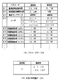
図7は、主基板31のCPU56が実行する遊技制御プログラム中で参照されるテーブルの構成例を示す説明図である。テーブルはROM54に設けられている。図7(A)には、通常時(確変状態でないとき)および確変時に使用されるパラメータ(状態変数)が格納されているパラメータテーブルの構成例を示す。後述するように、パラメータテーブルに設定されている各パラメータをROM54から直接読み出すように遊技制御プログラムを構成することもできるし、ROM54から一旦RAM55におけるワークエリアに読み出してワークエリアから読み出すように遊技制御プログラムを構成することもできる。
【0054】
図7(A)に示すように、この例では、普通図柄変動時間(#1)、普通電動役物開放時間(可変入賞球装置:#2)、確変ランプデータ(#3)、リーチ振り分け率(この例ではリーチ用乱数と比較される値:#4)、特別図柄変動時間(#5〜#9)が例示されている。なお、特別図柄変動時間#6は、確変状態においてはずれ時の特別図柄の変動が短縮される場合を考慮して設けられている。また、図7(A)に示された数値は一例であって、例えば、特別図柄の変動時間は確変時の方が短くてもよい。
【0055】
以下、遊技制御プログラムによってパラメータが読み出されるテーブルを指定テーブルという。パラメータがROM54のテーブルからそのまま読み出されるときには図7(A)に示されたパラメータテーブルが指定テーブルに相当するが、一度RAM55にデータが転送された後に、すなわちRAM55上にテーブルが再構築された後にデータが読み出される場合には、RAM55上のテーブルが指定テーブルに相当する。しかし、便宜上、指定テーブルは図7(A)に示されたテーブルであるとして説明を進める場合がある。
【0056】
また、図7(B)は、大当りとするか否か判定するときの判定値が設定されている大当り判定値テーブルを示す。後述するように、大当り判定時に、抽出されたランダム1(大当り判定用乱数)と大当り判定値テーブル中の値が一致すると大当りとされる。
【0057】
図8は、図7(A)に示された指定テーブルのROMにおけるデータ配列の一例を示す説明図である。図8に示された例では、先頭アドレスAAAAから通常時に使用されるパラメータが順次設定されている。また、先頭アドレスBBBBから確変時に使用されるパラメータが順次設定されている。なお、通常時のパラメータと確変時のパラメータとでは、同じパラメータは、先頭アドレスに対して同一のオフセット分離れた位置に設定されている。
【0058】
例えば、通常時の#4のリーチ振り分け率が先頭アドレスAAAAからm番地離れたアドレスに設定されているとすると、確変時の#4のリーチ振り分け率は先頭アドレスBBBBからm番地離れたアドレスに設定されている。
【0059】
なお、図7(A)に示すように、この例では、リーチ振り分け率は、ランダム6(リーチ用乱数)と比較される値として設定されている。例えば、通常時に実行されるリーチの種類を判定するときに、ランダム6の値が0〜14のいずれかであれば、リーチ1の態様でリーチ動作を行うことに決定され、15〜24のいずれかであれば、リーチ2の態様でリーチ動作を行うことに決定され、25〜29のいずれかであれば、リーチ3の態様でリーチ動作を行うことに決定される。
【0060】
次に、始動入賞口14への入賞にもとづいて可変表示部9に可変表示される図柄の決定方法について図9〜図11のフローチャートを参照して説明する。図9は打球が始動入賞口14に入賞したことを判定する処理を示し、図10は可変表示部9の可変表示の停止図柄を決定する処理を示す。図11は、大当りとするか否か決定する処理を示すフローチャートである。
【0061】
打球が遊技盤6に設けられている始動入賞口14に入賞すると、始動口センサ17がオンする。ステップS10のスイッチ処理において、CPU56は、スイッチ回路58を介して始動口センサ17がオンしたことを判定すると(ステップS41)、始動入賞記憶数が最大値である4に達しているかどうか確認する(ステップS42)。
【0062】
始動入賞記憶数が4に達していなければ、始動入賞記憶数を1増やし(ステップS43)、大当り図柄判定用乱数の値を抽出する。そして、それを始動入賞記憶数の値に対応した乱数値格納エリアに格納する(ステップS44)。なお、始動入賞記憶数が4に達している場合には、始動入賞記憶数を増やす処理を行わない。すなわち、この実施の形態では、最大4個の始動入賞口17に入賞した打球数が記憶可能である。
【0063】
図10に示すように、CPU56は、ステップS8の特別図柄プロセス処理において始動入賞記憶数の値を確認する(ステップS50)。始動入賞記憶数が0でなければ、始動入賞記憶数=1に対応する乱数値格納エリアに格納されている値を読み出すとともに(ステップS51)、始動入賞記憶数の値を1減らし、かつ、各乱数値格納エリアの値をシフトする(ステップS52)。すなわち、始動入賞記憶数=n(n=2,3,4)に対応する乱数値格納エリアに格納されている値を、始動入賞記憶数=n−1に対応する乱数値格納エリアに格納する。
【0064】
そして、CPU56は、ステップS51で読み出した値、すなわち抽出されている大当り図柄判定用乱数の値にもとづいて当たり/はずれを決定する(ステップS53)。ここでは、大当り図柄判定用乱数は0〜299の範囲の値をとることにする。図11に示すように、その値が図7(B)に示された大当り判定値テーブルに設定されている値と一致した場合に「大当り」と決定し、それ以外の値である場合には「はずれ」と決定する。なお、ステップS53の判断において、確変フラグによって現時点が通常時か確変時かの判断がなされ、通常時には図7(B)に示されたテーブルにおける通常時の値が使用され、確変時には図7(B)に示されたテーブルにおける確変時の値が使用される。
【0065】
大当たりと判定されたときには、CPU56は、大当り図柄が確率変動状態に移行させるためのあらかじめ決められている確変図柄であるか否か判定する(ステップS54)。確変図柄であれば、確変フラグをオンし(ステップS56)、そうでなければ確変フラグをオフする(ステップS55)。すなわち、この例では、確変状態は、次の大当り発生まで継続する。なお、実際に確変状態に移行するのは、特別図柄が確定(停止)し、それにもとづく大当り遊技が終了してからである。
【0066】
さらに、CPU56は、大当り予告を行うか否か決定する。すなわち、大当り予告用乱数(ランダム5)の値を抽出し、その値が0または1ならば大当り予告を行うことに決定する(ステップS65)。また、リーチ用乱数(ランダム6)を抽出しその値にもとづいてリーチ種類を決定する(ステップS57)。上述したように、CPU56は、指定テーブルの#4に設定されている値に応じてリーチ種類を決定する。
【0067】
ステップS53においてはずれと判定された場合には、CPU56は、リーチとするか否か判定する(ステップS58)。例えば、リーチ判定用の乱数であるランダム4の値が「105」〜「1530」のいずれかである場合には、リーチとしないと決定する。そして、リーチ判定用乱数の値が「0」〜「104」のいずれかである場合にはリーチとすることを決定する。リーチとすることを決定したときには、CPU56は、リーチ図柄の決定を行う。
【0068】
この実施の形態では、ランダム2−1の値に従って左右図柄を決定する(ステップS59)。また、ランダム2−2の値に従って中図柄を決定する(ステップS60)。すなわち、ランダム2−1およびランダム2−2の値の0〜15の値に対応したいずれかの図柄が停止図柄として決定される。ここで、決定された中図柄が左右図柄と一致した場合には、中図柄に対応した乱数の値に1加算した値に対応する図柄を中図柄の確定図柄として、大当たり図柄と一致しないようにする。
【0069】
さらに、CPU56は、大当り予告用乱数(ランダム5)の値を抽出し、その値が0または1ならば大当り予告を行うことに決定する(ステップS66)。また、リーチ用乱数(ランダム6)を抽出しその値にもとづいてリーチ種類を決定する(ステップS57)。
【0070】
ステップS58において、リーチしないことに決定された場合には、ランダム2−1〜2−3の値に応じて左右中図柄を決定する(ステップS61)。
以上のようにして、始動入賞にもとづく図柄変動の表示態様が大当たりとするか、リーチ態様とするか、はずれとするか決定され、それぞれの停止図柄の組合せが決定される。
なお、この実施の形態で用いられた乱数および乱数値の範囲は一例であって、どのような乱数を用いてもよいし、範囲設定も任意である。
【0071】
また、高確率状態において、次に大当たりとなる確率が上昇するとともに、7セグメントLEDによる可変表示器10の可変表示の確定までの時間が短縮され、かつ、可変表示器10の可変表示結果にもとづく当たり時の可変入賞球装置15の開放回数および開放時間が高められるようにパチンコ遊技機1が構成されていてもよいし、可変表示器10の可変表示結果にもとづく当たりの確率が高くなるように構成されていてもよい。また、それらのうちのいずれか一つまたは複数の状態のみが生ずるパチンコ遊技機1においても本発明は適用可能である。
【0072】
すなわち、特別遊技状態とは、特別図柄による大当り確率が高められることによって遊技者に所定の遊技価値が付与可能となる状態を生じ易くする場合の他に、普通図柄の変動時間が短縮されることや普通図柄による当り確率が高められることによって遊技者に所定の遊技価値が付与可能となる状態を生じ易くする場合も含まれる概念である。
【0073】
図12は、CPU56が実行する特別図柄プロセス処理のプログラムの一例を示すフローチャートである。図12に示す特別図柄プロセス処理は、図5のフローチャートにおけるステップS11の具体的な処理である。CPU56は、特別図柄プロセス処理を行う際に、その内部状態に応じて、図12に示すステップS300〜S309のうちのいずれかの処理を行う。各処理において、以下のような処理が実行される。
【0074】
特別図柄変動待ち処理(ステップS300):始動入賞口14(この実施の形態では可変入賞球装置15の入賞口)に打球入賞して始動口センサ17がオンするのを待つ。始動口センサ17がオンすると、始動入賞記憶数が満タンでなければ、始動入賞記憶数を+1するとともに大当り判定用乱数を抽出する。すなわち、図9に示された処理が実行される。
特別図柄判定処理(ステップS301):特別図柄の可変表示が開始できる状態になると、始動入賞記憶数を確認する。始動入賞記憶数が0でなければ、抽出されている大当り判定用乱数の値に応じて大当たりとするかはずれとするか決定する。すなわち、図10に示された処理の前半が実行される。
停止図柄設定処理(ステップS302):左右中図柄の停止図柄を決定する。すなわち、図10に示された処理の中半が実行される。
【0075】
リーチ動作設定処理(ステップS303):リーチ判定用乱数の値に応じてリーチ動作するか否か決定するとともに、リーチ用乱数の値に応じてリーチ時の変動期間を決定する。すなわち、図10に示された処理の後半が実行される。
【0076】
全図柄変動開始処理(ステップS304):可変表示部9において全図柄が変動開始されるように制御する。このとき、表示制御基板80に対して、左右中最終停止図柄と変動期間を指令する情報とが送信される。また、可変表示部9に背景やキャラクタも表示される場合には、それに応じた表示制御コマンドデータが表示制御基板80に送出されるように制御する。
【0077】
全図柄停止待ち処理(ステップS305):変動期間が終了するのを待ち、変動期間が経過すると、例えば、可変表示部9において表示される全図柄を停止すべきことを示す全図柄停止コマンドが表示制御基板80に送出されるように制御する。
【0078】
大当たり表示処理(ステップS306):停止図柄が大当たり図柄の組み合わせである場合には、内部状態(プロセスフラグ)をステップS307に移行するように更新する。そうでない場合には、内部状態をステップS309に移行するように更新する。なお、大当たり図柄の組み合わせは、左右中図柄が揃った組み合わせである。また、左右図柄が揃うとリーチとなる。
【0079】
大入賞口開放開始処理(ステップS307):大入賞口を開放する制御を開始する。具体的には、カウンタやフラグを初期化するとともに、ソレノイド21を駆動して大入賞口を開放する。
【0080】
大入賞口開放中処理(ステップS308):大入賞口ラウンド表示の表示制御コマンドデータが表示制御基板80に送出する制御や大入賞口の閉成条件の成立を確認する処理等を行う。大入賞口の閉成条件が成立したら、大当り遊技状態の終了条件が成立していなければ内部状態をステップS307に移行するように更新する。大当り遊技状態の終了条件が成立していれば、内部状態をステップS309に移行するように更新する。
【0081】
大当たり終了処理(ステップS309):大当たり遊技状態が終了したことを遊技者に報知するための表示を行う。その表示が終了したら、内部フラグ等を初期状態に戻し、内部状態をステップS300に移行するように更新する。
【0082】
上述したように、始動入賞口14に打球が入賞すると、基本回路53は、ステップS11(図5参照)の特別図柄プロセス処理において、大当たりとするかはずれとするか、停止図柄および可変表示期間を決定するが、その決定に応じた表示制御コマンドを表示制御基板80の表示制御用CPU101に与える。表示制御用CPU101は、主基板31からの表示制御コマンドに応じて可変表示部9の表示制御を行う。
【0083】
図13は、特別図柄プロセス処理におけるステップS309の主要な処理を示すフローチャートである。CPU56は、ステップS309において、確変フラグがオンしているか否か判定する(ステップS309a)。そして、確変フラグがオンしていれば、図7(A)に示された指定テーブルのうちの確変時テーブルを指定する(ステップS309b)。また、確変フラグがオンしていなければ、図7(A)に示された指定テーブルのうちの通常時テーブルを指定する(ステップS309c)。
【0084】
そして、指定されたテーブルを指定テーブルとして設定する(ステップS309d)。具体的には、ステップS309bまたはS309cの処理は、例えば、先頭アドレスAAAAまたは先頭アドレスBBBBをCPU56内部のレジスタに設定する処理である。そして、ステップS309dの処理では、レジスタに設定された値がそのまま保存されるか、または、所定のRAM領域に設定される。従って、この場合には、先頭アドレスAAAAまたは先頭アドレスBBBBを指すポインタの値が保存される。
【0085】
あるいは、先頭アドレスAAAAまたは先頭アドレスBBBBからの各パラメータを所定のRAM領域(ワークエリア)に転送し、そのRAM領域の先頭アドレスをレジスタまたは所定のRAM領域に設定してもよい。この場合には、確変フラグがオンしていたら先頭アドレスBBBBからの各パラメータ値がRAM55の所定の先頭アドレスから設定され、確変フラグがオフしていたら先頭アドレスAAAAからの各パラメータ値がRAM55の所定の先頭アドレスから設定される。そして、RAM領域の先頭アドレスを指すポインタの値が保存される。
【0086】
なお、この場合には、RAM領域内のデータが変更されるので、RAM領域の先頭アドレスを指すポインタの値は常に同じでよい。従って、この場合には、ステップS309dの処理を行わなくてもよい。
【0087】
図14は、遊技制御プログラム中で、図7(A)に示されたような指定テーブルに設定されている各パラメータを扱う部分の処理を示すフローチャートである。上述した例では、例えば、図10に示されたステップS57の処理において、指定テーブルに設定されているパラメータが扱われている。そこでは、#4のパラメータが扱われている。
【0088】
図14に示されたように、CPU56は、指定テーブルに設定されているパラメータを扱うときに、まず、保存されている指定テーブルの先頭アドレスをレジスタに設定する。先頭アドレスがレジスタに保存されているときには、そのレジスタ値をそのまま使用できる。そして、先頭アドレスからそのときに扱うパラメータ格納位置までのオフセットを先頭アドレスに加算する(ステップS91)。例えば、#4のパラメータを扱う場合、#1〜#3の領域がそれぞれ2バイトで構成されているときには、ステップS91の演算によって先頭アドレス+6がレジスタに演算結果として残る(1バイト/1アドレスの場合)。
【0089】
次いで、CPU56は、演算結果が設定されているレジスタの値をアドレスとして、そのアドレスに設定されているデータを読み出す(ステップS92)。読み出されたデータは、一般に、アドレスが設定されているレジスタとは異なるレジスタにロードされる。そして、レジスタにロードされたデータにもとづく処理が行われる(ステップS93)。
【0090】
例えば、#4のパラメータを扱う場合、抽出されているランダム6の値とレジスタにロードされたデータとの比較が行われる。なお、この例では、#4のパラメータを扱う場合には指定テーブルから複数のデータを読み出す必要があるので、図14に示された処理が繰り返し実行される。例えば、指定テーブルにおけるリーチ1,2,3に対応したそれぞれの領域の最後および#4の領域全体の最後に終了コードが設定され、終了コードが見つかるまで繰り返し実行される。
【0091】
図15は、遊技制御プログラム中で、図7(A)に示されたような指定テーブルに設定されている各パラメータを扱う部分の他の処理例を示すフローチャートである。この例でも、CPU56は、まず、保存されている指定テーブルの先頭アドレスをレジスタに設定する(ステップS94)。先頭アドレスがレジスタに保存されているときには、そのレジスタ値をそのまま使用できる。
【0092】
次いで、CPU56は、オフセットを指定してレジスタ値が指すアドレスのデータをロードする命令を実行する(ステップS95)。通常、CPUにはインデックスレジスタが設けられ、そのインデックスレジスタと数値によるオフセットとを指定すると、インデックスレジスタ値+オフセットをアドレッシングする命令が備えられている。従って、この例では、先頭アドレスがインデックスレジスタに設定される。インデックスレジスタ値+オフセットをアドレッシングする命令の実行によってアドレッシングされたアドレスのデータがレジスタにロードされる。そして、レジスタにロードされたデータにもとづく処理が行われる(ステップS96)。
【0093】
図14に示された例ではパラメータが設定されているアドレスを直接的に指定してデータがロードされ、図15に示された例ではインデックスレジスタを介して間接的にアドレスが指定されデータがロードされる。いずれの方式を採用しても、指定テーブルに設定されている各パラメータを扱う場合には、通常時であるのか確変時であるのかを判断する必要はない。図13に示されたステップS309の処理によって、状態に応じた指定テーブルの先頭アドレスが保存され、かつ、図8に示されたように、通常時でも確変時でも、同一パラメータの先頭アドレスからの距離(アドレス差=オフセット)は同じだからである。
【0094】
従って、各パラメータを扱う場合に、対応するパラメータについてのオフセットを与えれば、通常時と確変時とを特に意識しなくても、通常時には通常時用のパラメータを扱うことができ、確変時には確変時用のパラメータを扱うことができる。各パラメータを扱う際に通常時であるのか確変時であるのかを判断しなくてよいので、すなわち、そのような判断を行うステップが不要になるので、遊技制御プログラムの容量を少なくすることができる。
【0095】
以下、一例として、図7(A)に示された#1および#2のパラメータを使用する普通図柄変動制御について説明する。図16は、図5に示されたメイン処理における普通図柄プロセス処理を示すフローチャートである。CPU56は、普通図柄プロセス処理を行う際に、その内部状態に応じて、図16に示すステップS400〜S404のうちのいずれかの処理を行う。各処理において、以下のような処理が実行される。
【0096】
打球が通過ゲート11を通過してゲートスイッチ12がオンすると、通過記憶数が満タンでなければ、通過記憶数が+1されるとともに普通図柄判定用乱数が抽出される。普通図柄判定用乱数は図6には図示されなかったが、普通図柄判定用乱数を生成するためのカウンタは、やはりメイン処理(図5参照)の判定用乱数更新処理(ステップS10)で更新されている。なお、遊技機には通過記憶数を報知するための表示手段が設けられているが、図1では記載省略されている。
【0097】
普通図柄変動待ち処理(ステップS400):普通図柄の変動を開始できる状態になると、抽出されている普通図柄判定用乱数と当り判定値とを比較して当りとするか否かを決定する。当りとする場合に、当り図柄が複数ある場合には、いずれの図柄で当りとするのかも決定する。
【0098】
普通図柄変動開始処理(ステップS401):普通図柄の変動期間を決めるためのタイマをスタートさせて可変表示器10における普通図柄の変動を開始する。
【0099】
普通図柄変動中処理(ステップS402):1図柄変動の時間が経過すると、可変表示器10の表示図柄を次の図柄とする。そして、変動時間が終了すると普通図柄の変動を停止する。
【0100】
普通電動役物開放開始処理(ステップS403):停止図柄が当り図柄であれば、普通電動役物(この例では、可変入賞球装置15)の動作期間(可変入賞球装置15の開放期間)を決めるためのタイマをスタートさせ、可変入賞球装置15を開くためのソレノイド16をオンする。
【0101】
普通電動役物開放中処理(ステップS404):可変入賞球装置15の動作期間を決めるためのタイマがタイムアウトすると、可変入賞球装置15を開くためのソレノイド16をオフする。
【0102】
図17は、普通図柄変動待ち処理(ステップS400)を示すフローチャートである。普通図柄変動待ち処理において、CPU56は、通過記憶数が0でなければ(ステップS400a)、通過記憶数=1に対応する乱数値格納エリアに格納されている値を読み出すとともに(ステップS400b)、通過記憶数の値を1減らし、かつ、各乱数値格納エリアの値をシフトする(ステップS400c)。すなわち、通過記憶数=n(n=2,3,4)に対応する乱数値格納エリアに格納されている値を、通過記憶数=n−1に対応する乱数値格納エリアに格納する。
【0103】
次に、読み出された乱数値と当り判定とを比較する(ステップS400d)。当たり判定値と一致すれば、当り図柄を決定する(ステップS400e)。そして、普通図柄プロセスフラグを普通図柄変動開始待ち処理(ステップS401)に対応した値にする(ステップS400f)。
【0104】
図18は、普通図柄変動開始待ち処理(ステップS401)を示すフローチャートである。普通図柄変動開始待ち処理において、CPU56は、まず、指定テーブルから#1のパラメータ値を読み出す(ステップS401a)。そして、読み出した値を普通図柄変動タイマに設定しタイマをスタートさせる。この例では、通常時には29.5秒のタイマがスタートされ確変時には5.1秒のタイマがスタートされる。なお、指定テーブルからのパラメータ値読み出しの方法は、図14や図15のフローチャートに示されたとおりである。
【0105】
次に、1図柄の変動に対応した時間を示す値を変動速度タイマに設定してタイマをスタートさせ(ステップS401b)、普通図柄プロセスフラグを普通図柄変動中処理(ステップS402)に対応した値にする(ステップS401c)。
【0106】
図19は、普通図柄変動中処理(ステップS402)を示すフローチャートである。普通図柄変動中処理において、CPU56は、普通図柄変動タイマがタイムアウトしたか否か判断する(ステップS402a)。タイムアウトしていれば、可変表示器10における普通図柄の変動を停止し(ステップ402e)、普通図柄プロセスフラグを普通電動役物開放開始処理(ステップS403)に対応した値にする(ステップS401f)。
【0107】
普通図柄変動タイマがタイムアウトしていなければ、変動速度タイマがタイムアウトしたか否か判断する(ステップS402b)。タイムアウトしていれば、可変表示器10における表示図柄を次の図柄とする(ステップS402c)。また、変動速度タイマを再設定する(ステップS402d)。
【0108】
図20は、普通電動役物開放開始処理(ステップS403)を示すフローチャートである。普通電動役物開放開始処理において、CPU56は、可変入賞球装置15を開くためのソレノイド16をオンする(ステップS403a)。次いで、指定テーブルから#2のパラメータ値を読み出す(ステップS403b)。そして、読み出した値を開放タイマに設定しタイマをスタートさせる。
【0109】
この例では、通常時には0.2秒のタイマがスタートされ確変時には4秒のタイマがスタートされる。すなわち、通常時には可変入賞球装置15が0.2秒間開放し、確変時には4秒間開放する。なお、指定テーブルからのパラメータ値読み出しの方法は、図14や図15のフローチャートに示されたとおりである。また、可変入賞球装置15の開放回数が複数回とされている遊技機もあるが、そのような遊技機にも対応できるように、指定テーブルに、普通電動役物開放回数を示すパラメータ設定領域を設けてもよい。
【0110】
開放タイマをスタートさせたら、CPU56は、普通図柄プロセスフラグを普通電動役物開放中処理(ステップS404)に対応した値にする(ステップS403c)。なお、普通電動役物開放中処理では、開放タイマがタイムアウトしたらソレノイド16がオフされる。
【0111】
以上のように、普通図柄および普通電動役物に関する制御時に使用されるパラメータ値は、指定テーブルから読み出される。指定テーブルに設定されている各パラメータを扱う場合には、通常時であるのか確変時であるのかを判断する必要はない。すなわち、各パラメータを扱う場合に、対応するパラメータについてのオフセットを与えれば、通常時と確変時とを特に意識しなくても、通常時には通常時用のパラメータを扱うことができ、確変時には確変時用のパラメータを扱うことができる。
【0112】
上記の実施の形態のように、通常時および確変時のパラメータを指定テーブルに設定し、各処理モジュールでは指定テーブルの先頭アドレスに対してオフセットを与えてパラメータ値を読み出すようにすれば、各処理モジュールにおいて通常時であるのか確変時であるのかを判断しなくてよいのでプログラムステップ数が節減される。しかし、本発明によれば、そのような効果だけでなく、他機種にプログラムを流用する場合に最小限の変更で済むという効果もある。
【0113】
図21は、他の機種において用いられるパラメータテーブル(指定テーブル)および大当り判定値テーブルの例を示す説明図である。図21(B)に示すように、この例では、確変時の大当り確率が通常時の10倍とされている。また、図21(A)に示すように、普通図柄の変動および普通電動役物に関するパラメータ値は、通常時と確変時とで同じになっている。
【0114】
図21(A)に示されたテーブルにおけるパラメータの配置および各パラメータのメモリでのサイズは、図7(A)に示されたテーブルにおけるそれらと同じになっている。従って、図7(A)に示されたテーブルを使用する遊技機のプログラムを図21(A)に示されたテーブルを使用する遊技機に流用する場合に、テーブル設定を変えるだけでよい。指定テーブル内の各パラメータを扱う部分には変更をかけなくてもよい。
【0115】
図22は、図21(A)に示されたテーブルを用いる遊技機における可変表示部9の可変表示の停止図柄を決定する処理の一例を示すフローチャートである。この例では、図10に示された処理に対して、確変フラグをオンオフする部分のみが異なっている。すなわち、確変図柄で大当りとすることに決定されると、確変フラグがオンされるのであるが(ステップS56)、同時に、始動入賞記憶数+1の値がワークエリアに保存される(ステップS75)。
【0116】
そして、図23に示すように、特別図柄プロセス処理における全図柄停止待ち処理(ステップS305)において、ワークエリアの設定値が0でなければ(ステップS305a)、ワークエリアの内容が−1される(ステップS305b)。そして、−1後のワークエリアの設定値が0であれば(ステップS305c)、確変フラグがオフされる(ステップS305d)。その後、特別図柄プロセスフラグの値が次のプロセスに対応した値に設定される(ステップS305e)。なお、全図柄停止待ち処理は特別図柄変動中に実行される処理であるから特別図柄変動制御に関する処理も行われているが、図23では省略されている。
【0117】
この遊技機では、確変大当りが発生すると、その後、始動入賞記憶数に応じた回数分の特別図柄の変動が完了するまで確変フラグがオンされている。なお、図22におけるステップS75で始動入賞記憶数+1が設定されるのは、確変大当り発生時の特別図柄の変動が確変継続回数に含まれないようにするためである。
【0118】
図24は、図21(A)に示されたテーブルを用いる遊技機における可変表示部9の可変表示の停止図柄を決定する処理の他の例を示すフローチャートである。この例でも、図10に示された処理に対して、確変フラグをオンオフする部分のみが異なっている。すなわち、確変図柄で大当りとすることに決定されると、確変フラグがオンされるのであるが(ステップS56)、同時に、所定値(この例では50)がワークエリアに保存される(ステップS75)。
【0119】
そして、図23に示されたような特別図柄プロセス処理における全図柄停止待ち処理(ステップS305)において、ワークエリアの内容の−1処理と確変フラグオフ処理が行われる。よって、この遊技機では、確変大当りが発生すると、その後、50回の特別図柄の変動が完了するまで確変フラグがオンされている。
【0120】
なお、図24におけるステップS76で設定される値を指定テーブルに設定されるパラメータとしてもよい。そのように指定テーブルを構成する場合には、確変状態終了の条件として特別図柄変動回数を使用しない遊技機では、指定テーブルの該当個所に例えばFFFF(H)(10進で65535)が設定される。
【0121】
以上の各実施の形態に示されたように、遊技制御プログラムを、通常時および確変時のパラメータを指定テーブルに設定し、各処理モジュールでは指定テーブルの先頭アドレスに対してオフセットを与えてパラメータ値を読み出すように構成すれば、プログラムステップ数が節減されるとともに、他機種にプログラムを流用する場合等におけるプログラム変更を最小限で済ませることができる。
【0122】
なお、上記の各実施の形態では、指定テーブルに設定されているパラメータ値の使用例として、リーチ種類および普通図柄に関する制御を挙げた。しかし、通常時と確変時とで異なる値が用いられる可能性のあるその他のパラメータも指定テーブルに設定しておくのがよい。例えば、図7(A)や図21(A)にはその他のパラメータの一例として、確変ランプデータが示されている。
【0123】
確変状態ではランプやLEDによって確変状態であることを遊技者に報知する必要がある。ランプやLEDの制御は、例えばメイン処理(図5参照)におけるランプタイマ処理(ステップS7)で行われるのであるが、その処理においても、通常状態であるのか確変状態であるのか判定する必要はない。上述したように、状態に応じた指定テーブルの先頭アドレスが設定されているので、ランプタイマ処理では、確変ランプデータに対応したオフセットを指定するだけで、そのときの状態に応じたパラメータを入手できる。この場合、パラメータは、ランプやLEDの点灯パターンを示すデータである。従って、通常/確変の判断を行うことなく、状態に応じたランプやLEDの点灯制御を行うことができる。
【0124】
なお、上記の各実施の形態では、大当り判定値は指定テーブルに含まれていない。指定テーブルをワークエリア(RAM)に再構築して使用する場合にはその内容がノイズ等によって変更されてしまう可能性があるが、大当り判定値が指定テーブルに含まれないので、その値が変わってしまうことはない。すなわち、遊技者に有利な遊技価値を発生させるための条件が変わってしまうことはなく、遊技者に大きな不利益が与えられることは防止される。
【0125】
【発明の効果】
以上のように、本発明によれば、遊技機を、遊技者に所定の遊技価値が付与可能となる状態を生じやすい特別遊技状態とそれ以外の通常状態とで異なる遊技制御を行うプログラム部分で使用される各パラメータが設定される状態変数テーブルがROMに格納され、状態変数テーブル中で、通常状態の各パラメータとそれに対応する特別遊技状態の各パラメータとはそれぞれ同一順序で設定され、かつ、通常状態の各パラメータの先頭アドレスからのアドレス差は特別遊技状態の各パラメータの先頭アドレスからのアドレス差と同一であるように設定され、CPUは、特定遊技状態に移行させる前に特別遊技状態にするか否か判定し、該特定遊技状態が終了したときに、特別遊技状態にすると判定されている場合には特別遊技状態の各パラメータの先頭アドレスを示すデータを保存し、特別遊技状態にしないと判定されている場合には通常状態の各パラメータの先頭アドレスを示すデータを保存し、次に特定遊技状態に移行されて該特定遊技状態が終了するまで先頭アドレスを示すデータの保存状態を変更せず、保存されている先頭アドレスを示すデータに対して読み出すパラメータに対応するアドレス差であって通常状態でも特別遊技状態でも同一のアドレス差を、保存されている先頭アドレスを示すデータに加算した値を用いてアドレス指定を行うことによって状態変数テーブルから当該パラメータを入手し、入手したパラメータに従って演出装置を制御するように構成されているので、各処理モジュールにおいて特別遊技状態であるか否かの判定を行わずに済み、プログラム容量が低減され、かつプログラム変更も容易になる効果がある。また、いずれの状態にあっても一つのポインタによってパラメータを格納している箇所を指定することができ、プログラム構成を効率化することができる。また、各処理モジュールは、通常状態であるか特別遊技状態であるかを意識せずに、保存されている先頭アドレスによって必要なパラメータ値を入力できる。また、オフセットの指定のみで直ちに必要なパラメータ値を入力できる。また、普通図柄の変動時間が異なる他機種へのプログラム流用が容易になる効果がある。また、可変入賞球装置の動作時間が異なる他機種へのプログラム流用が容易になる効果がある。また、遊技制御プログラムにおける発光体制御部分は、通常状態であるのか確変状態であるのか判定することなく発光体の点灯態様を状態に合わせたものとすることができる。
【0133】
状態変数テーブルには、遊技者に所定の遊技価値が付与可能となる状態を発生させるか否か判定するための判定値が含まれないように構成されている場合には、状態変数テーブルをワークエリアに再構築して使用する場合であっても、判定値がノイズによって変化することがないという効果がある。
【図面の簡単な説明】
【図1】 パチンコ遊技機を正面からみた正面図である。
【図2】 パチンコ遊技機の内部構造を示す全体背面図である。
【図3】 パチンコ遊技機の遊技盤を背面からみた背面図である。
【図4】 主基板における回路構成の一例を示すブロック図である。
【図5】 基本回路のメイン処理を示すフローチャートである。
【図6】 各乱数を示す説明図である。
【図7】 遊技制御プログラム中で参照されるテーブルの構成例を示す説明図である。
【図8】 指定テーブルにおけるデータ配列の一例を示す説明図である。
【図9】 打球が始動入賞口に入賞したことを判定する処理を示すフローチャートである。
【図10】 可変表示の停止図柄を決定する処理およびリーチ種類を決定する処理を示すフローチャートである。
【図11】 大当たり判定の処理を示すフローチャートである。
【図12】 特別図柄プロセス処理を示すフローチャートである。
【図13】 大当り終了処理の主要部を示すフローチャートである。
【図14】 指定テーブル中のパラメータを使用するプログラム例を示すフローチャートである。
【図15】 指定テーブル中のパラメータを使用するプログラムの他の例を示すフローチャートである。
【図16】 普通図柄プロセス処理を示すフローチャートである。
【図17】 普通図柄変動待ち処理を示すフローチャートである。
【図18】 普通図柄変動開始処理を示すフローチャートである。
【図19】 普通図柄変動中処理を示すフローチャートである。
【図20】 普通電動役物開放開始処理を示すフローチャートである。
【図21】 指定テーブルにおけるデータ配列の他の例を示す説明図である。
【図22】 可変表示の停止図柄を決定する処理およびリーチ種類を決定する他の処理を示すフローチャートである。
【図23】 全図柄停止待ち処理の一例を示すフローチャートである。
【図24】 可変表示の停止図柄を決定する処理およびリーチ種類を決定するさらに他の処理を示すフローチャートである。
【符号の説明】
9 可変表示部
10 可変表示器
15 可変入賞球装置
16 ソレノイド
31 遊技制御基板(主基板)
53 基本回路
54 ROM
55 RAM
56 CPU[0001]
BACKGROUND OF THE INVENTION
The present invention relates to a gaming machine such as a pachinko gaming machine or a coin gaming machine, and particularly includes a variable display device whose display state can be changed, and a display result in the variable display device becomes a predetermined specific display mode. The present invention relates to a gaming machine that can be given a predetermined gaming value.
[0002]
[Prior art]
As a gaming machine, a variable display device having a variable display unit whose display state can be changed is provided, and a big hit game that is advantageous to the player when the display result of the variable display unit becomes a predetermined specific display mode Some are configured to transition to a state. The variable display device has a plurality of variable display units, and is usually configured to display the display results of the plurality of variable display units at different times. For example, special symbols are variably displayed on the variable display section.
[0003]
That the display result of the variable display unit is a combination of specific display modes determined in advance is usually referred to as “big hit”. Note that the game value is the right that the state of the variable winning ball device provided in the gaming area of the gaming machine is advantageous for a player who is likely to win a ball, or the advantageous state for a player. It is to generate.
[0004]
When a big hit occurs, for example, the big winning opening is opened a predetermined number of times, and the game shifts to a big hit gaming state in which a hit ball is easy to win. And in each open period, if there is a prize for a predetermined number (for example, 10) of the big prize opening, the big prize opening is closed. And the number of times the special winning opening is opened is fixed to a predetermined number (for example, 16 rounds). An opening time (for example, 29.5 seconds) is determined for each opening, and even if the number of winnings does not reach a predetermined number, the big winning opening is closed when the opening time elapses. In addition, when a predetermined condition (for example, winning in a V zone provided in the big prize opening) is not established at the time when the big prize opening is closed, the big hit game even if the predetermined number of times is not reached The state ends.
[0005]
In addition, among the combinations of “out of” display modes other than the “big hit” combination, the display results are already derived and displayed at a stage where some of the display results of the plurality of variable display portions have not yet been derived and displayed. A state in which the display mode of the variable display unit satisfies a display condition that is a combination of specific display modes is referred to as “reach”. A player plays a game while enjoying how to generate a big hit.
[0006]
Some gaming machines improve the probability of generating a big hit when a predetermined condition is established. The predetermined condition is satisfied, for example, when the combination of the stop symbol of the special symbol becomes a combination of the predetermined symbol (probability variation symbol). A state in which the probability of generating a big hit is improved is called a probability variation (probability variation) state. In a gaming machine having a function of shifting to a probability changing state, the player plays a game while enjoying how to generate a combination of special symbols that are conditions for shifting to the probability changing state.
[0007]
In addition, some gaming machines normally display symbols in a variable manner. Normal symbols are simple symbols and numbers compared to special symbols. When the predetermined condition is satisfied, variable display of the normal symbol is started, and when the stop symbol matches the winning symbol, the so-called electric accessory is opened and the game ball is easily won. In this case, the variable display period of the normal symbol may be shortened or the opening time of the electric accessory may be lengthened in the probability variation state described above. In addition, there are cases in which different game control is performed in the probability variation state and the state in which it is not.
Each game control described above is executed by game control means, and the game control means is generally configured to include a microcomputer, so that each game control is realized by a program executed by the microcomputer.
[0008]
[Problems to be solved by the invention]
Normally, there is a limit on the capacity of the program storage area (ROM) that can be installed in a gaming machine, so if the amount of programs for realizing each game control can be reduced, a game with a more complicated performance will be realized as a whole. can do. However, generally, when trying to compress the program capacity, the program content tends to become complicated. This is because each function is realized with a shorter number of steps. As the program content becomes complicated, it becomes difficult to divert a program of one model to another model.
[0009]
Although it is preferable that the game machine development period is short, if the program can be easily diverted, the game machine development period can be shortened as a result. However, if an attempt is made to achieve an effect with a higher gaming effect, it is difficult to divert the program to other models for the reasons described above. From the above, it is a big problem in gaming machines that a program capable of realizing a more complicated game effect can be realized with a low capacity, and that the program can be easily diverted to other models.
[0010]
In view of the above, an object of the present invention is to provide a gaming machine including a game control means in which the program capacity is reduced and the program can be easily changed.
[0011]
[Means for Solving the Problems]
The gaming machine according to the present invention plays a game based on the player's operation,Display result of variable display deviceButCombination of specific display modesBecamesometimesA gaming machine capable of shifting to a specific gaming state advantageous to a player,Equipped with a variable display that variably displays normal symbols,The CPU that controls the progress of the game performs the game control based on the game control program stored in the ROM, and a special game state in which a predetermined game value can easily be given to the player, and other normal states A state variable table in which a plurality of parameters used in the program part for performing game control are set in ROM in different storage areas is stored in the ROM, and each parameter in the normal state and a special corresponding to it are stored in the state variable table. Each parameter in the gaming state is set in the same order, and the address difference from the starting address of each parameter in the normal gaming state is set to be the same as the address difference from the starting address of each parameter in the special gaming state. , CPUIt is determined whether or not to enter the special gaming state before shifting to the specific gaming state, and when it is determined that the special gaming state is set when the specific gaming state ends, the start address of each parameter of the special gaming state Is stored when it is determined not to enter the special gaming state.Save the data indicating the start address of each parameter in the status,Next, the display result is already derived and displayed at the stage where the display result is not derived and displayed on the variable display device without changing the storage state of the data indicating the head address until the specific gaming state is completed after the transition to the specific gaming state. A selection process for selecting a reach state satisfying a display condition in which the displayed display mode is a combination of specific display modes is selected from a plurality of types, and the state variable table includes a state in which a game medium is easy to win. Information that can specify the variation time of the normal symbol for determining the operating condition of the variable winning ball device that can be changed to a state that is difficult to win, information that indicates the operating time of the variable winning ball device, and light emission that indicates the special gaming state Information that can identify the lighting pattern of the body and reach selection data for selecting which reach type to select in the selection process are included.SaveHas beenStores the same address difference in the normal state and special game state corresponding to the parameter to be read for the data indicating the start address.Has beenBy specifying the address using the value added to the data indicating the start addressFrom the state variable tableThe parameter is obtained, and the rendering device is controlled according to the obtained parameter.
[0019]
It is preferable that the state variable table does not include a determination value for determining whether or not to generate a state (for example, a big hit state) in which a predetermined game value can be given to the player.
[0020]
DETAILED DESCRIPTION OF THE INVENTION
Hereinafter, an embodiment of the present invention will be described with reference to the drawings.
First, the overall configuration of a pachinko gaming machine that is an example of a gaming machine will be described. 1 is a front view of the
[0021]
As shown in FIG. 1, the
[0022]
Near the center of the
[0023]
The hit ball that has passed through the passing
[0024]
An open / close plate 20 that is opened by a
[0025]
At the bottom of the
[0026]
The
[0027]
In this example, a
[0028]
The hit ball fired from the hit ball launching device enters the
[0029]
The rotation of the image in the
[0030]
When the combination of images in the
[0031]
Further, when the stop symbol on the
[0032]
Next, the structure of the back surface of the
On the back surface of the
[0033]
The
[0034]
FIG. 3 is a rear view of the game board of the
[0035]
In order to perform the winning ball payout control, signals from the winning
[0036]
For example, when the winning
[0037]
FIG. 4 is a block diagram illustrating an example of a circuit configuration in the main board 31. FIG. 4 also shows a prize
[0038]
Further, according to the data given from the basic circuit 53, the jackpot information indicating the occurrence of the jackpot, the effective starting information indicating the number of starting winning balls used for starting the image display of the
[0039]
The basic circuit 53 includes a
[0040]
Further, an
Note that there is also switch information input to the main board 31 from the ball dispensing device 97, but these are omitted in FIG.
[0041]
A ball hitting device for hitting and launching a game ball is driven by a
[0042]
Next, the operation of the gaming machine will be described.
FIG. 5 is a flowchart showing the operation of the basic circuit 53 on the main board 31. As described above, this processing is started, for example, every 2 ms by a reset pulse generated by the
[0043]
Next, the CPU 56 performs a stack setting process for setting the designated address of the stack pointer (step S2). In this example, 00FFH is set in the stack pointer. Then, a system check process is performed (step S3). In the system check process, the CPU 56 determines whether or not an error is included in the RAM 55. If the error is included, the CPU 56 performs a process such as initializing the RAM 55.
[0044]
Next, after performing processing for setting command data sent to the display control board 80 in a predetermined area of the RAM 55 (display control data setting processing: step S4), processing for outputting the command data as display control command data is performed. Performed (display control data output processing: step S5).
[0045]
Next, a process of outputting the contents of the storage area for various output data to each output port is performed (data output process: step S6). Also, the process of decrementing the lamp timer by 1 is performed, and when the lamp timer times out (= 0), the lamp data pointer is updated and a new value is set in the lamp timer (lamp timer process: step S7).
[0046]
Further, output data setting processing is performed for setting output data such as address data indicated by the lamp data pointer, jackpot information output to the hall management computer, start information, probability variation information, etc. in the storage area (step S8). Further, various abnormality diagnosis processes are performed by the self-diagnosis function provided in the
[0047]
Next, a process of updating each counter indicating each determination random number such as a big hit determination random number used for game control is performed (step S10).
FIG. 6 is an explanatory diagram showing each random number. Each random number is used as follows.
(1) Random 1: Decide whether or not to generate a big hit (for big hit determination = special symbol determination)
(2) Random 2-1 to 2-3: For determining the left and right out-of-line symbols
(3) Random 3: The combination of symbols at the time of jackpot is determined (for jackpot symbol determination = special symbol judgment)
(4) Random 4: Decide whether or not to reach when falling off (for reach determination)
(5) Random 5: Decide whether or not to make a jackpot notice (for jackpot notice)
(6) Random 6: Determine reach type (for reach)
[0048]
In order to enhance the game effect, random numbers other than the random numbers (1) to (6) are also used.
In step S10, the CPU 56 counts up (adds 1) a counter for generating the jackpot determination random number (1) and the jackpot symbol determination random number (3). That is, they are determination random numbers.
[0049]
Next, the CPU 56 performs special symbol process processing (step S11). In the special symbol process control, corresponding processing is selected and executed according to a special symbol process flag for controlling the
[0050]
Further, the CPU 56 inputs the state of each switch via the
[0051]
The basic circuit 53 further performs a process of updating the display random number (step S15). That is, the counter for generating
[0052]
The basic circuit 53 performs signal processing with the prize ball control board 37 (step S16). That is, when a predetermined condition is satisfied, a prize ball control command indicating the number of prize balls is output to the prize
After that, the basic circuit 53 repeats the display random number update process in step S17 until the next reset pulse is given from the
[0053]
FIG. 7 is an explanatory diagram showing a configuration example of a table referred to in the game control program executed by the CPU 56 of the main board 31. The table is provided in the
[0054]
As shown in FIG. 7A, in this example, the normal symbol variation time (# 1), the normal electric accessory release time (variable winning ball device: # 2), the probability variation ramp data (# 3), the reach distribution rate (In this example, the value compared with the reach random number: # 4), the special symbol variation time (# 5- # 9) is illustrated. Note that the special symbol
[0055]
Hereinafter, a table from which parameters are read by the game control program is referred to as a designation table. When the parameters are read from the table of the
[0056]
FIG. 7B shows a jackpot determination value table in which a determination value for determining whether or not to win is set. As will be described later, at the time of jackpot determination, if the extracted random 1 (big hit determination random number) matches the value in the jackpot determination value table, a jackpot is determined.
[0057]
FIG. 8 is an explanatory diagram showing an example of a data arrangement in the ROM of the designation table shown in FIG. In the example shown in FIG. 8, the parameters that are normally used are set sequentially from the start address AAAA. Further, parameters used at the time of probability change are sequentially set from the head address BBBB. It should be noted that the same parameter is set at the same offset-separated position with respect to the start address in the normal parameter and the parameter at the time of probability change.
[0058]
For example, if the reach distribution rate of # 4 at the normal time is set to an address that is separated from the start address AAAA by m addresses, the reach distribution rate of # 4 at the time of probability change is set to an address that is separated from the start address BBBB by m addresses. Has been.
[0059]
As shown in FIG. 7A, in this example, the reach distribution rate is set as a value to be compared with random 6 (reach random number). For example, when the type of reach that is normally executed is determined, if the value of random 6 is any of 0 to 14, it is determined to perform the reach operation in the form of
[0060]
Next, a method for determining a symbol variably displayed on the
[0061]
When the hit ball wins the
[0062]
If the starting winning memory number has not reached 4, the starting winning memory number is increased by 1 (step S43), and the value of the random number for jackpot symbol determination is extracted. Then, it is stored in a random value storage area corresponding to the value of the number of stored start winning prizes (step S44). When the start winning memory number has reached 4, the process for increasing the starting win memory number is not performed. That is, in this embodiment, it is possible to store the number of hit balls that have been won in a maximum of four start winning
[0063]
As shown in FIG. 10, the CPU 56 confirms the value of the number of start winning prizes stored in the special symbol process in step S8 (step S50). If the starting winning memory number is not 0, the value stored in the random number value storage area corresponding to the starting winning memory number = 1 is read (step S51), the value of the starting winning memory number is decreased by 1, and each The value in the random value storage area is shifted (step S52). That is, the value stored in the random number value storage area corresponding to the starting winning memory number = n (n = 2, 3, 4) is stored in the random number value storing area corresponding to the starting winning memory number = n−1. .
[0064]
Then, the CPU 56 determines the winning / losing based on the value read in step S51, that is, the extracted value of the jackpot symbol determining random number (step S53). Here, the jackpot symbol determining random number takes a value in the range of 0-299. As shown in FIG. 11, when the value matches the value set in the jackpot determination value table shown in FIG. 7B, the jackpot is determined, and when the value is other than that, It is determined as “out of”. In the determination of step S53, it is determined whether the current time is the normal time or the probability change time by the probability change flag, and the normal value in the table shown in FIG. 7B is used in the normal state. The value at the time of probability change in the table shown in B) is used.
[0065]
When it is determined that the jackpot is determined, the CPU 56 determines whether or not the jackpot symbol is a predetermined probability variation symbol for shifting to the probability variation state (step S54). If it is a probability variation symbol, the probability variation flag is turned on (step S56),soIf not, the probability variation flag is turned off (step S55). That is, in this example, the probability variation state continues until the next jackpot occurrence. Note that the actual transition to the probability change state is after the special symbol is confirmed (stopped) and the big hit game based on the special symbol ends.
[0066]
Further, the CPU 56 determines whether or not to make a jackpot notice. That is, the value of the random number for jackpot warning (random 5) is extracted, and if the value is 0 or 1, it is decided to perform the jackpot warning (step S65). Further, the reach random number (random 6) is extracted and the reach type is determined based on the value (step S57). As described above, the CPU 56 determines the reach type according to the value set in # 4 of the designation table.
[0067]
If it is determined in step S53 that there is a gap, the CPU 56 determines whether or not to reach (step S58). For example, when the value of random 4, which is a random number for reach determination, is any one of “105” to “1530”, it is determined not to reach. If the value of the reach determination random number is any one of “0” to “104”, it is determined to reach. When determining to reach, the CPU 56 determines the reach symbol.
[0068]
In this embodiment, the left and right symbols are determined according to the value of random 2-1 (step S59). Further, the medium symbol is determined according to the value of random 2-2 (step S60). That is, any symbol corresponding to 0 to 15 of random 2-1 and random 2-2 is determined as a stop symbol. Here, when the determined middle symbol matches the left and right symbols, the symbol corresponding to the value obtained by adding 1 to the random number value corresponding to the middle symbol is set as the determined symbol of the middle symbol so as not to match the jackpot symbol To do.
[0069]
Furthermore, the CPU 56 extracts the value of the random number for jackpot warning (random 5), and if the value is 0 or 1, it determines to perform the jackpot warning (step S66). Further, the reach random number (random 6) is extracted and the reach type is determined based on the value (step S57).
[0070]
If it is decided not to reach in step S58, the left and right middle symbols are decided according to the random values 2-1 to 2-3 (step S61).
As described above, it is determined whether the display mode of the symbol variation based on the start winning is a big hit, a reach mode, or a deviation mode, and a combination of each stop symbol is determined.
Note that the random number and the range of random number values used in this embodiment are examples, and any random number may be used, and the range setting is also arbitrary.
[0071]
Further, in the high probability state, the probability of the next big hit increases, the time until the variable display of the
[0072]
In other words, the special game state means that, in addition to the case where it is easy to generate a state in which a predetermined game value can be given to the player by increasing the probability of jackpot due to the special symbol, the fluctuation time of the normal symbol is reduced. It is also a concept that includes a case where it is easy to generate a state in which a predetermined game value can be given to a player by increasing the probability of hitting with a normal symbol.
[0073]
FIG. 12 is a flowchart illustrating an example of a special symbol process processing program executed by the CPU 56. The special symbol process shown in FIG. 12 is a specific process of step S11 in the flowchart of FIG. When performing the special symbol process, the CPU 56 performs any one of steps S300 to S309 shown in FIG. 12 according to the internal state. In each process, the following process is executed.
[0074]
Special symbol variation waiting process (step S300): Waiting for the
Special symbol determination process (step S301): When variable symbol special display can be started, the number of start winning memories is confirmed. If the starting winning memorization number is not 0, it is determined whether to win or not depending on the value of the extracted jackpot determination random number. That is, the first half of the process shown in FIG. 10 is executed.
Stop symbol setting process (step S302): The stop symbol of the middle left and right symbols is determined. That is, the middle half of the process shown in FIG. 10 is executed.
[0075]
Reach operation setting processing (step S303): It is determined whether or not a reach operation is performed according to the value of the reach determination random number, and a variation period during reach is determined according to the value of the reach random number. That is, the second half of the process shown in FIG. 10 is executed.
[0076]
All symbol variation start processing (step S304): Control is performed so that the
[0077]
All symbol stop waiting process (step S305): Waiting for the end of the variable period. When the variable period elapses, for example, an all symbol stop command indicating that all symbols displayed on the
[0078]
Jackpot display processing (step S306): If the stop symbol is a combination of jackpot symbols, the internal state (process flag) is updated to shift to step S307. If not, the internal state is updated to shift to step S309. The jackpot symbol combination is a combination of right and left middle symbols. Reaching is achieved when the left and right symbols are aligned.
[0079]
Big winning opening opening process (step S307): Control for opening the big winning opening is started. Specifically, the counter and the flag are initialized, and the
[0080]
Processing for opening a special prize opening (step S308): Control for sending display control command data for the big prize opening round display to the display control board 80, processing for confirming establishment of a closing condition for the special prize opening, and the like. If the closing condition for the big prize opening is satisfied, the internal state is updated to shift to step S307 if the end condition for the big hit gaming state is not satisfied. If the end condition for the big hit gaming state is satisfied, the internal state is updated to shift to step S309.
[0081]
Jackpot end process (step S309): A display for notifying the player that the jackpot gaming state has ended is performed. When the display is completed, the internal flag and the like are returned to the initial state, and the internal state is updated to shift to step S300.
[0082]
As described above, when a hit ball is won at the
[0083]
FIG. 13 is a flowchart showing the main processing of step S309 in the special symbol process. In step S309, the CPU 56 determines whether or not the probability variation flag is on (step S309a). If the probability variation flag is on, the probability variation time table of the designation table shown in FIG. 7A is designated (step S309b). If the probability variation flag is not turned on, the normal time table of the specified table shown in FIG. 7A is specified (step S309c).
[0084]
Then, the specified table is set as the specified table (step S309d). Specifically, the process of step S309b or S309c is a process of setting the start address AAAA or the start address BBBB in a register inside the CPU 56, for example. In the process of step S309d, the value set in the register is stored as it is or is set in a predetermined RAM area. Therefore, in this case, the value of the pointer pointing to the start address AAAA or the start address BBBB is stored.
[0085]
Alternatively, each parameter from the start address AAAA or the start address BBBB may be transferred to a predetermined RAM area (work area), and the start address of the RAM area may be set in a register or a predetermined RAM area. In this case, each parameter value from the head address BBBB is set from a predetermined head address in the RAM 55 if the probability variation flag is on, and each parameter value from the head address AAAA is a predetermined value in the RAM 55 if the probability variation flag is off. It is set from the first address. Then, a pointer value indicating the start address of the RAM area is stored.
[0086]
In this case, since the data in the RAM area is changed, the value of the pointer indicating the start address of the RAM area may always be the same. Therefore, in this case, step S309d need not be performed.
[0087]
FIG. 14 is a flowchart showing the process of the part that handles each parameter set in the designation table as shown in FIG. 7A in the game control program. In the example described above, for example, the parameters set in the designation table are handled in the process of step S57 shown in FIG. There, the
[0088]
As shown in FIG. 14, when handling the parameters set in the specified table, the CPU 56 first sets the head address of the stored specified table in the register. When the start address is stored in the register, the register value can be used as it is. Then, an offset from the head address to the parameter storage position handled at that time is added to the head address (step S91). For example, when the
[0089]
Next, the CPU 56 uses the value of the register in which the calculation result is set as an address, and reads data set at the address (step S92). The read data is generally loaded into a register different from the register in which the address is set. Then, processing based on the data loaded in the register is performed (step S93).
[0090]
For example, when the
[0091]
FIG. 15 is a flowchart showing another example of processing for handling each parameter set in the designation table as shown in FIG. 7A in the game control program. Also in this example, the CPU 56 first sets the start address of the stored designation table in the register (step S94). When the start address is stored in the register, the register value can be used as it is.
[0092]
Next, the CPU 56 executes an instruction for designating an offset and loading data at an address indicated by the register value (step S95). Normally, an index register is provided in the CPU, and an instruction for addressing the index register value + offset is provided when the index register and a numerical offset are designated. Therefore, in this example, the head address is set in the index register. The data at the address addressed by the execution of the instruction addressing the index register value + offset is loaded into the register. Then, processing based on the data loaded into the register is performed (step S96).
[0093]
In the example shown in FIG. 14, data is loaded by directly specifying the address where the parameter is set, and in the example shown in FIG. 15, the address is specified indirectly via the index register and the data is loaded. Is done. Regardless of which method is employed, when each parameter set in the specified table is handled, it is not necessary to determine whether it is a normal time or a probability change time. By the process of step S309 shown in FIG. 13, the start address of the designation table corresponding to the state is saved, and as shown in FIG. This is because the distance (address difference = offset) is the same.
[0094]
Therefore, when each parameter is handled, if the offset for the corresponding parameter is given, the normal time parameter can be handled in normal time and the normal time parameter can be handled without any special consideration. Can handle parameters for Since it is not necessary to determine whether it is a normal time or a probable change when handling each parameter, that is, since the step for making such a determination becomes unnecessary, the capacity of the game control program can be reduced. .
[0095]
Hereinafter, as an example, the normal symbol variation control using the
[0096]
When the hit ball passes through the passing
[0097]
Normal symbol variation waiting process (step S400): When the normal symbol variation can be started, the extracted normal symbol random number is compared with the hit determination value to determine whether or not to win. In the case of winning, if there are a plurality of winning symbols, it is also determined which symbol is the winning symbol.
[0098]
Normal symbol variation start processing (step S401): A timer for determining the variation period of the ordinary symbol is started to start variation of the ordinary symbol on the
[0099]
Normal symbol variation processing (step S402): When the symbol variation time elapses, the display symbol of the
[0100]
Normal electric accessory release start process (step S403): If the stop symbol is a winning symbol, the operation period of the normal electric accessory (in this example, the variable winning ball device 15) (the opening period of the variable winning ball device 15) is set. A timer for determining is started, and a
[0101]
Processing during opening of ordinary electric accessory (step S404): When the timer for determining the operation period of the variable winning
[0102]
FIG. 17 is a flowchart showing the normal symbol variation waiting process (step S400). In the normal symbol variation waiting process, the CPU 56 reads the value stored in the random number storage area corresponding to the passing memory count = 1 if the passing memory count is not 0 (step S400a) (step S400b). The value of the stored number is reduced by 1 and the value of each random number storage area is shifted (step S400c). That is, the value stored in the random number storage area corresponding to the passing memory number = n (n = 2, 3, 4) is stored in the random value storing area corresponding to the passing memory number = n−1.
[0103]
Next, the read random number value is compared with the hit determination (step S400d). If it matches the winning determination value, the winning symbol is determined (step S400e). Then, the normal symbol process flag is set to a value corresponding to the normal symbol variation start waiting process (step S401) (step S400f).
[0104]
FIG. 18 is a flowchart showing the normal symbol variation start waiting process (step S401). In the normal symbol variation start waiting process, the CPU 56 first reads the parameter value of # 1 from the designation table (step S401a). Then, the read value is set in the normal symbol variation timer and the timer is started. In this example, a 29.5 second timer is normally started, and a 5.1 second timer is started when the probability is changed. Note that the method of reading the parameter value from the designation table is as shown in the flowcharts of FIGS.
[0105]
Next, a value indicating the time corresponding to the variation of one symbol is set in the variation speed timer and the timer is started (step S401b), and the normal symbol process flag is set to a value corresponding to the normal symbol variation processing (step S402). (Step S401c).
[0106]
FIG. 19 is a flowchart showing the normal symbol variation processing (step S402). In the normal symbol variation processing, the CPU 56 determines whether or not the normal symbol variation timer has timed out (step S402a). If time-out has occurred, the variation of the normal symbol on the
[0107]
If the normal symbol variation timer has not timed out, it is determined whether or not the variation rate timer has timed out (step S402b). If time-out has occurred, the display symbol on the
[0108]
FIG. 20 is a flowchart showing the ordinary electric accessory release start process (step S403). In the ordinary electric accessory release start process, the CPU 56 turns on the
[0109]
In this example, a 0.2 second timer is normally started, and a 4 second timer is started when the probability changes. In other words, the variable winning
[0110]
When the release timer is started, the CPU 56 sets the normal symbol process flag to a value corresponding to the process for releasing the normal electric accessory (step S404) (step S403c). In the process of opening the ordinary electric accessory, the
[0111]
As described above, the parameter values used at the time of control related to the normal symbol and the ordinary electric accessory are read from the designation table. When handling each parameter set in the specified table, it is not necessary to determine whether it is normal time or probability change time. In other words, when each parameter is handled, if the offset for the corresponding parameter is given, the normal time parameter can be handled in normal time and the normal time parameter can be handled without any special consideration. Can handle parameters for
[0112]
As in the above-described embodiment, each process module is configured so that parameters at normal time and probability change are set in the specified table, and each processing module reads the parameter value by giving an offset to the start address of the specified table. Since it is not necessary to determine whether the module is in normal or probable change, the number of program steps is saved. However, according to the present invention, not only such an effect but also an effect that a minimum change is required when the program is diverted to another model.
[0113]
FIG. 21 is an explanatory diagram showing an example of a parameter table (designation table) and a jackpot determination value table used in other models. As shown in FIG. 21B, in this example, the jackpot probability at the time of probability change is set to 10 times that at the normal time. Further, as shown in FIG. 21A, the parameter values regarding the variation of the normal symbol and the normal electric accessory are the same at the normal time and at the time of the probability change.
[0114]
The arrangement of parameters in the table shown in FIG. 21A and the size of each parameter in the memory are the same as those in the table shown in FIG. Therefore, when the game machine program using the table shown in FIG. 7A is diverted to the game machine using the table shown in FIG. 21A, it is only necessary to change the table setting. There is no need to change the part that handles each parameter in the specified table.
[0115]
FIG. 22 is a flowchart showing an example of processing for determining a variable display stop symbol of the
[0116]
Then, as shown in FIG. 23, in the all symbol stop waiting process (step S305) in the special symbol process, if the set value of the work area is not 0 (step S305a), the content of the work area is decremented by 1 ( Step S305b). If the set value of the work area after −1 is 0 (step S305c), the probability variation flag is turned off (step S305d). Thereafter, the value of the special symbol process flag is set to a value corresponding to the next process (step S305e). Note that the all symbol stop waiting process is a process executed during the special symbol variation, and therefore a process related to the special symbol variation control is also performed, but is omitted in FIG.
[0117]
In this gaming machine, when the probability variation jackpot occurs, the probability variation flag is turned on until the variation of the special symbol for the number of times corresponding to the number of start winning memories is completed. The reason why the start winning memorized number +1 is set in step S75 in FIG. 22 is to prevent the variation in the special symbol when the probability variation big hit occurs from being included in the probability variation continuation number.
[0118]
FIG. 24 is a flowchart showing another example of the process for determining the variable display stop symbol of the
[0119]
Then, in the all symbol stop waiting process (step S305) in the special symbol process as shown in FIG. 23, the -1 process of the contents of the work area and the probability variation flag off process are performed. Therefore, in this gaming machine, when the probability variation big hit occurs, the probability variation flag is turned on until the variation of 50 special symbols is completed thereafter.
[0120]
Note that the value set in step S76 in FIG. 24 may be a parameter set in the designation table. In the case where the designation table is configured in such a manner, for a gaming machine that does not use the special symbol variation count as a condition for ending the probability variation state, for example, FFFF (H) (decimal 65535) is set at a corresponding portion of the designation table. .
[0121]
As shown in each of the above embodiments, the game control program sets the normal time and probability change parameters in the specified table, and each processing module gives an offset to the start address of the specified table and sets the parameter value. If the configuration is such that the number of program steps is read, the number of program steps can be reduced, and the program change when diverting the program to another model can be minimized.
[0122]
In each of the above-described embodiments, the control relating to the reach type and the normal symbol is given as an example of using the parameter value set in the designation table. However, it is also preferable to set other parameters in the specification table that may use different values between the normal time and the probability change time. For example, FIG. 7A and FIG. 21A show probability variation ramp data as an example of other parameters.
[0123]
In the probability variation state, it is necessary to notify the player that the probability variation state is present using a lamp or LED. The control of the lamp and LED is performed, for example, in the lamp timer process (step S7) in the main process (see FIG. 5), but even in this process, it is not necessary to determine whether it is a normal state or a probable state. . As described above, since the head address of the specification table corresponding to the state is set, in the ramp timer process, the parameter corresponding to the state at that time can be obtained simply by specifying the offset corresponding to the probability variation lamp data. . In this case, the parameter is data indicating the lighting pattern of the lamp or LED. Therefore, it is possible to perform lighting control of the lamp and the LED according to the state without performing the determination of normal / accuracy.
[0124]
In each of the above embodiments, the jackpot determination value is not included in the designation table. When the specified table is reconstructed and used in the work area (RAM), its contents may be changed due to noise, etc., but the value will change because the specified value is not included in the specified table. There is no end to it. That is, the condition for generating a game value advantageous to the player is not changed, and it is possible to prevent the player from being greatly disadvantaged.
[0125]
【The invention's effect】
As described above, according to the present invention, the gaming machine is a program part that performs different game control in a special game state that is likely to give a player a predetermined game value and a normal state other than that. A state variable table in which each parameter to be used is set is stored in the ROM, and in the state variable table, each parameter in the normal state and each parameter in the special gaming state corresponding thereto are set in the same order, and The address difference from the head address of each parameter in the normal state is set to be the same as the address difference from the head address of each parameter in the special gaming state, and the CPUIt is determined whether or not to enter the special gaming state before shifting to the specific gaming state, and when it is determined that the special gaming state is set when the specific gaming state ends, the start address of each parameter of the special gaming state Is stored when it is determined not to enter the special gaming state.Save the data indicating the start address of each parameter in the status,Next, without changing the storage state of the data indicating the head address until the specific gaming state is finished after the transition to the specific gaming state,SaveHas beenStores the same address difference in the normal state and special game state corresponding to the parameter to be read for the data indicating the start address.Has beenBy specifying the address using the value added to the data indicating the start addressFrom the state variable tableSince it is configured to obtain the parameter and control the effect device according to the obtained parameter, it is not necessary to determine whether each processing module is in a special gaming state, the program capacity is reduced, and The program can be easily changed.In any state, the location where the parameters are stored can be specified by one pointer, and the program configuration can be made efficient. Further, each processing module can input a necessary parameter value based on the stored head address without being conscious of whether it is a normal state or a special game state. In addition, necessary parameter values can be input immediately by only specifying the offset. Also, there is an effect that the program can be easily used for other models with different normal symbol fluctuation times. In addition, there is an effect that the program can be easily diverted to other models having different operation times of the variable winning ball apparatus. In addition, the light emitter control portion in the game control program can match the lighting mode of the light emitter with the state without determining whether the light emitter is in the normal state or the probability variation state.
[0133]
If the state variable table is configured not to include a determination value for determining whether or not to generate a state in which a predetermined game value can be given to the player, the state variable table Even when the area is reconstructed and used, there is an effect that the determination value does not change due to noise.
[Brief description of the drawings]
FIG. 1 is a front view of a pachinko gaming machine as viewed from the front.
FIG. 2 is an overall rear view showing the internal structure of the pachinko gaming machine.
FIG. 3 is a rear view of the game board of the pachinko gaming machine as viewed from the back.
FIG. 4 is a block diagram illustrating an example of a circuit configuration on a main board.
FIG. 5 is a flowchart showing main processing of the basic circuit.
FIG. 6 is an explanatory diagram showing each random number.
FIG. 7 is an explanatory diagram showing a configuration example of a table referred to in the game control program.
FIG. 8 is an explanatory diagram showing an example of a data array in a designation table.
FIG. 9 is a flowchart showing a process of determining that a hit ball has won a start winning opening.
FIG. 10 is a flowchart showing processing for determining a variable display stop symbol and processing for determining a reach type.
FIG. 11 is a flowchart showing a jackpot determination process.
FIG. 12 is a flowchart showing a special symbol process.
FIG. 13 is a flowchart showing a main part of a big hit end process.
FIG. 14 is a flowchart illustrating an example of a program that uses parameters in a specification table.
FIG. 15 is a flowchart showing another example of a program that uses parameters in a specification table.
FIG. 16 is a flowchart showing a normal symbol process.
FIG. 17 is a flowchart showing normal symbol variation waiting processing;
FIG. 18 is a flowchart showing normal symbol variation start processing;
FIG. 19 is a flowchart showing normal symbol variation processing;
FIG. 20 is a flowchart showing a normal electric accessory release start process.
FIG. 21 is an explanatory diagram showing another example of the data arrangement in the designation table.
FIG. 22 is a flowchart showing a process for determining a variable display stop symbol and another process for determining a reach type.
FIG. 23 is a flowchart showing an example of all symbol stop waiting processing;
FIG. 24 is a flowchart showing a process for determining a variable display stop symbol and a further process for determining a reach type.
[Explanation of symbols]
9 Variable display section
10 Variable display
15 Variable winning ball equipment
16 Solenoid
31 Game control board (main board)
53 Basic circuit
54 ROM
55 RAM
56 CPU
Claims (2)
普通図柄を可変表示する可変表示器を備え、
遊技の進行を制御するCPUはROMに格納されている遊技制御プログラムにもとづいて遊技制御を行い、
遊技者に所定の遊技価値が付与可能となる状態を生じやすい特別遊技状態とそれ以外の通常状態とで異なる格納領域に、遊技制御を行うプログラム部分で使用される複数のパラメータがそれぞれ設定された状態変数テーブルが前記ROMに格納され、
前記状態変数テーブル中で、前記通常状態の各パラメータとそれに対応する前記特別遊技状態の各パラメータとはそれぞれ同一順序で設定され、かつ、前記通常状態の各パラメータの先頭アドレスからのアドレス差は前記特別遊技状態の各パラメータの先頭アドレスからのアドレス差と同一であるように設定され、
前記CPUは、
前記特定遊技状態に移行させる前に前記特別遊技状態にするか否か判定し、該特定遊技状態が終了したときに、前記特別遊技状態にすると判定されている場合には前記特別遊技状態の各パラメータの先頭アドレスを示すデータを保存し、前記特別遊技状態にしないと判定されている場合には前記通常状態の各パラメータの先頭アドレスを示すデータを保存し、次に特定遊技状態に移行されて該特定遊技状態が終了するまで先頭アドレスを示すデータの保存状態を変更せず、
前記可変表示装置に表示結果が導出表示されていない段階で既に表示結果が導出表示されている表示態様が特定の表示態様の組合せとなる表示条件を満たしているリーチ状態を複数種類のうちから選択する選択処理を実行し、
前記状態変数テーブルには、遊技媒体が入賞しやすい状態と入賞しにくい状態とに可変可能な可変入賞球装置の動作条件を決めるための前記普通図柄の変動時間を特定可能な情報と、前記可変入賞球装置の動作時間を示す情報と、前記特別遊技状態を示す発光体の点灯パターンを特定可能な情報と、前記選択処理でいずれのリーチ種類とするのか選択するためのリーチ選択用データとが含まれ、
前記CPUは、保存されている先頭アドレスを示すデータに対して読み出すパラメータに対応するアドレス差であって前記通常状態でも前記特別遊技状態でも同一のアドレス差を、保存されている先頭アドレスを示すデータに加算した値を用いてアドレス指定を行うことによって前記状態変数テーブルから当該パラメータを入手し、入手したパラメータに従って演出装置を制御する
ことを特徴とする遊技機。A gaming machine that performs a game based on a player's operation and is capable of shifting to a specific gaming state advantageous to the player when the display result of the variable display device is a combination of specific display modes ,
Equipped with a variable display that variably displays normal symbols,
The CPU that controls the progress of the game performs the game control based on the game control program stored in the ROM,
A plurality of parameters used in the program part for controlling the game are set in different storage areas in the special game state and the normal state other than the normal game state in which the player can easily give a predetermined game value. A state variable table is stored in the ROM;
In the state variable table, each parameter in the normal state and each parameter in the special gaming state corresponding thereto are set in the same order, and the address difference from the start address of each parameter in the normal state is It is set to be the same as the address difference from the top address of each parameter in the special gaming state,
The CPU
It is determined whether or not to enter the special gaming state before the transition to the specific gaming state, and when it is determined to enter the special gaming state when the specific gaming state ends, each of the special gaming state Data indicating the start address of the parameter is stored, and if it is determined not to enter the special gaming state, the data indicating the start address of each parameter in the normal state is stored, and then the transition to the specific gaming state is performed. The storage state of the data indicating the head address is not changed until the specific gaming state ends,
Select from among a plurality of types of reach states that satisfy a display condition in which the display mode in which the display result has already been derived and displayed at the stage where the display result is not derived and displayed on the variable display device is a combination of specific display modes Execute the selection process to
In the state variable table, information that can specify the variation time of the normal symbol for determining the operating condition of the variable winning ball apparatus that can be varied between a state where the game medium is easy to win and a state where it is difficult to win, and the variable Information indicating the operation time of the winning ball apparatus, information capable of specifying the lighting pattern of the light emitter indicating the special gaming state, and reach selection data for selecting which reach type is selected in the selection process Included,
Wherein the CPU, the data indicating the head address of the same address difference in the special game state in the normal state an address difference corresponding to the parameter to be read to the data indicating the leading address stored, are stored A gaming machine, wherein the parameter is obtained from the state variable table by performing addressing using a value added to, and the rendering device is controlled according to the obtained parameter.
請求項1記載の遊技機。Wherein the state variable table, the gaming machine according to claim 1, wherein not included determination value for the predetermined game value to determine whether to generate a state that enables awarded to a player.
Priority Applications (1)
| Application Number | Priority Date | Filing Date | Title |
|---|---|---|---|
| JP04918699A JP4420998B2 (en) | 1999-02-25 | 1999-02-25 | Game machine |
Applications Claiming Priority (1)
| Application Number | Priority Date | Filing Date | Title |
|---|---|---|---|
| JP04918699A JP4420998B2 (en) | 1999-02-25 | 1999-02-25 | Game machine |
Publications (3)
| Publication Number | Publication Date |
|---|---|
| JP2000245911A JP2000245911A (en) | 2000-09-12 |
| JP2000245911A5 JP2000245911A5 (en) | 2005-09-15 |
| JP4420998B2 true JP4420998B2 (en) | 2010-02-24 |
Family
ID=12824014
Family Applications (1)
| Application Number | Title | Priority Date | Filing Date |
|---|---|---|---|
| JP04918699A Expired - Fee Related JP4420998B2 (en) | 1999-02-25 | 1999-02-25 | Game machine |
Country Status (1)
| Country | Link |
|---|---|
| JP (1) | JP4420998B2 (en) |
Families Citing this family (7)
| Publication number | Priority date | Publication date | Assignee | Title |
|---|---|---|---|---|
| JP4233265B2 (en) * | 2002-03-29 | 2009-03-04 | 株式会社三共 | Game machine |
| JP2007167567A (en) * | 2005-12-26 | 2007-07-05 | Daiichi Shokai Co Ltd | Pachinko game machine |
| JP2007167583A (en) * | 2005-12-26 | 2007-07-05 | Daiichi Shokai Co Ltd | Pachinko game machine |
| JP2017023356A (en) * | 2015-07-21 | 2017-02-02 | 株式会社三共 | Game machine |
| JP2017023357A (en) * | 2015-07-21 | 2017-02-02 | 株式会社三共 | Game machine |
| JP6940883B2 (en) * | 2016-07-07 | 2021-09-29 | 株式会社ソフイア | Pachinko machine |
| JP6570094B1 (en) * | 2018-12-28 | 2019-09-04 | 株式会社オリンピア | Game machine |
-
1999
- 1999-02-25 JP JP04918699A patent/JP4420998B2/en not_active Expired - Fee Related
Also Published As
| Publication number | Publication date |
|---|---|
| JP2000245911A (en) | 2000-09-12 |
Similar Documents
| Publication | Publication Date | Title |
|---|---|---|
| JP3836265B2 (en) | Game machine | |
| JP6681149B2 (en) | Slot machine | |
| JP2002000833A (en) | Game machine | |
| JPH11216237A (en) | Game machine | |
| JP2010125195A (en) | Game machine | |
| JP4420998B2 (en) | Game machine | |
| JPH11300011A (en) | Game machine | |
| JP2006271750A (en) | Game machine | |
| JPH11299985A (en) | Game machine | |
| JP2000084143A (en) | Game machine | |
| JPH11239638A (en) | Game machine | |
| JPH11299986A (en) | Game machine | |
| JP2002058837A (en) | Game machine | |
| JP2000317070A (en) | Game machine | |
| JPH11285576A (en) | Game machine | |
| JPH11309242A (en) | Game machine | |
| JP2006230936A (en) | Game machine | |
| JP4271283B2 (en) | Game machine | |
| JP4435326B2 (en) | Game machine | |
| JP2006320536A (en) | Game machine | |
| JP2003019273A (en) | Game machine | |
| JP4436004B2 (en) | Gaming machine and gaming error processing method | |
| JP3961145B2 (en) | Game machine | |
| JP2004057282A (en) | Game machine | |
| JP2000176099A (en) | Game machine |
Legal Events
| Date | Code | Title | Description |
|---|---|---|---|
| A521 | Written amendment |
Free format text: JAPANESE INTERMEDIATE CODE: A523 Effective date: 20050324 |
|
| RD03 | Notification of appointment of power of attorney |
Free format text: JAPANESE INTERMEDIATE CODE: A7423 Effective date: 20060118 |
|
| A131 | Notification of reasons for refusal |
Free format text: JAPANESE INTERMEDIATE CODE: A131 Effective date: 20060404 |
|
| A521 | Written amendment |
Free format text: JAPANESE INTERMEDIATE CODE: A523 Effective date: 20060602 |
|
| A131 | Notification of reasons for refusal |
Free format text: JAPANESE INTERMEDIATE CODE: A131 Effective date: 20070130 |
|
| A521 | Written amendment |
Free format text: JAPANESE INTERMEDIATE CODE: A523 Effective date: 20070329 |
|
| A02 | Decision of refusal |
Free format text: JAPANESE INTERMEDIATE CODE: A02 Effective date: 20070828 |
|
| A521 | Written amendment |
Free format text: JAPANESE INTERMEDIATE CODE: A523 Effective date: 20070927 |
|
| A911 | Transfer of reconsideration by examiner before appeal (zenchi) |
Free format text: JAPANESE INTERMEDIATE CODE: A911 Effective date: 20071102 |
|
| A912 | Removal of reconsideration by examiner before appeal (zenchi) |
Free format text: JAPANESE INTERMEDIATE CODE: A912 Effective date: 20071122 |
|
| A01 | Written decision to grant a patent or to grant a registration (utility model) |
Free format text: JAPANESE INTERMEDIATE CODE: A01 |
|
| A61 | First payment of annual fees (during grant procedure) |
Free format text: JAPANESE INTERMEDIATE CODE: A61 Effective date: 20091202 |
|
| FPAY | Renewal fee payment (event date is renewal date of database) |
Free format text: PAYMENT UNTIL: 20121211 Year of fee payment: 3 |
|
| R150 | Certificate of patent or registration of utility model |
Ref document number: 4420998 Country of ref document: JP Free format text: JAPANESE INTERMEDIATE CODE: R150 Free format text: JAPANESE INTERMEDIATE CODE: R150 |
|
| FPAY | Renewal fee payment (event date is renewal date of database) |
Free format text: PAYMENT UNTIL: 20121211 Year of fee payment: 3 |
|
| FPAY | Renewal fee payment (event date is renewal date of database) |
Free format text: PAYMENT UNTIL: 20121211 Year of fee payment: 3 |
|
| FPAY | Renewal fee payment (event date is renewal date of database) |
Free format text: PAYMENT UNTIL: 20131211 Year of fee payment: 4 |
|
| R250 | Receipt of annual fees |
Free format text: JAPANESE INTERMEDIATE CODE: R250 |
|
| R250 | Receipt of annual fees |
Free format text: JAPANESE INTERMEDIATE CODE: R250 |
|
| R250 | Receipt of annual fees |
Free format text: JAPANESE INTERMEDIATE CODE: R250 |
|
| R250 | Receipt of annual fees |
Free format text: JAPANESE INTERMEDIATE CODE: R250 |
|
| R250 | Receipt of annual fees |
Free format text: JAPANESE INTERMEDIATE CODE: R250 |
|
| LAPS | Cancellation because of no payment of annual fees |