JP3920527B2 - Elevator for construction - Google Patents
Elevator for construction Download PDFInfo
- Publication number
- JP3920527B2 JP3920527B2 JP2000102489A JP2000102489A JP3920527B2 JP 3920527 B2 JP3920527 B2 JP 3920527B2 JP 2000102489 A JP2000102489 A JP 2000102489A JP 2000102489 A JP2000102489 A JP 2000102489A JP 3920527 B2 JP3920527 B2 JP 3920527B2
- Authority
- JP
- Japan
- Prior art keywords
- machine room
- car
- hoistway
- floor
- construction
- Prior art date
- Legal status (The legal status is an assumption and is not a legal conclusion. Google has not performed a legal analysis and makes no representation as to the accuracy of the status listed.)
- Expired - Lifetime
Links
Images


Landscapes
- Types And Forms Of Lifts (AREA)
Description
【0001】
【発明の属する技術分野】
本発明は、高層ビル等の建築工事現場で工事進行過程に応じて昇降路内の仮設機械室を上方へ移設することにより乗りかごを運行するサービス階を順次上方へ拡大していく工事用エレベータおよびその据付方法に関する。
【0002】
【従来の技術】
従来、例えば特開平8−133635号公報や特開平4−243786号公報に開示されているように、ビルの建築工事の進行過程に合わせて、昇降路内に仮設した機械室を上方へ移設していき、乗りかごの昇降行程を順次延長可能な工事用エレベータが提案されている。このような従来の工事用エレベータでは、高層ビルの建築工事現場であっても、エレベータが未完成の間に乗りかごを用いて上層階へ建築資材を運搬したり建設作業者を昇降できるので、ビル建築工事の効率化を図ることができる。
【0003】
【発明が解決しようとする課題】
ところで、前述した従来の工事用エレベータでは、仮設機械室を建築工事の進行に応じて昇降路内の上方に移設していくため、仮設機械室内の機器、すなわち制御盤、巻上げ機およびロープ送出し装置等をすべて昇降路寸法より狭い仮設機械室内に配置する必要があり、したがって、仮設機械室内にスペースの余裕がなくなり仮設機械室内の機器の保守・点検が困難であった。
【0004】
また、上述した仮設機械室内の機器を配置するために仮設機械室の高さ寸法を大きくする必要があるが、仮設機械室の高さ寸法を大きくした場合には、工場から建築現場までの運搬用トラックに載せた際に道路交通法上の高さ制限以下にすることが難しいため、仮設機械室を分割して運搬して現地で組み立てるという煩雑な手間が発生していた。
【0005】
また、上述した仮設機械室を建築現場のタワークレーン等の揚重設備により昇降路内に搬入するため、この揚重能力の制約を受けないよう、極力軽量化する必要があり、同時に、制御盤、巻上げ機等の機器を解体・搬出する揚重設備を仮設機械室内に設置するために仮設機械室自体の強度も必要であったが、この点への考慮が十分でなかった。
【0009】
本発明は、このような従来技術における実情に鑑みてなされたもので、その第1の目的は、仮設機械室内にスペースの余裕を設けることができ、仮設機械室内の機器の保守・点検作業を容易に行なうことのできる工事用エレベータを提供することにある。
【0010】
また、その第2の目的は、仮設機械室が軽量であり、搬入や移設に際して安全にかつ効率良く位置決め作業ができ、かつトラックで運搬しやすく現地でも容易に組立てることのできる工事用エレベータを提供することにある。
【0011】
また、その第3の目的は、完成した昇降路内から仮設機械室内の機器を効率よく解体・搬出することのできる工事用エレベータを提供することにある。
【0015】
【課題を解決するための手段】
上記第1の目的を達成するために、本発明の請求項1に係る発明は、建築中の建物の昇降路内に昇降可能に設けられる乗りかごおよびつり合いおもりと、前記昇降路内に立設され、前記乗りかごおよび前記つり合いおもりをそれぞれ案内する乗りかご用ガイドレールおよびつり合いおもり用ガイドレールと、前記昇降路内に納められ、前記建物の築造に合わせて順次前記乗りかご用ガイドレールに案内されて上方に移設される仮設機械室と、この仮設機械室に設けられ、前記乗りかごと前記つり合いおもりを釣瓶式で昇降させる主ロープが巻掛けられる巻上げ機とを有し、前記仮設機械室の移設に伴い前記乗りかごを運行するサービス階を上方へ拡大するようにした工事用エレベータにおいて、前記仮設機械室の床面に、前記乗りかご用ガイドレールが立設される側の昇降路壁面に向けて張り出され、前記ガイドレールの立設方向とほぼ直交する床面を形成する張出し床を着脱可能に備えたことを特徴する。
【0016】
このように構成した本発明の請求項1に係る発明では、仮設機械室の床面から、乗りかご用ガイドレールが立設される側の昇降路壁面に向けて張出し床が張り出しているので、その張出し床の分だけ仮設機械室内にスペースの余裕ができ、これによって、仮設機械室内の機器の保守・点検が容易になる。
【0017】
また、上記第2の目的を達成するために、本発明の請求項2に係る発明は、建築中の建物の昇降路内に昇降可能に設けられる乗りかごおよびつり合いおもりと、前記昇降路内に立設され、前記乗りかごおよび前記つり合いおもりをそれぞれ案内する乗りかご用ガイドレールおよびつり合いおもり用ガイドレールと、前記昇降路内に納められ、前記建物の築造に合わせて順次前記乗りかご用ガイドレールに案内されて上方に移設される仮設機械室と、この仮設機械室に設けられ、前記乗りかごと前記つり合いおもりを釣瓶式で昇降させる主ロープが巻掛けられる巻上げ機とを有し、前記仮設機械室の移設に伴い前記乗りかごを運行するサービス階を上方へ拡大するようにした工事用エレベータにおいて、前記仮設機械室が、前記巻上げ機および乗りかごの昇降を制御する制御盤、前記乗りかごの異常速度を検出するガバナ装置、および前記主ロープを保持するロープ固定装置とが予め組込まれるとともに、前記仮設機械室の床面に、前記乗りかご用ガイドレールが立設される側の昇降路壁面に向けて張り出され、前記乗りかご用ガイドレールの立設方向とほぼ直交する床面を形成する着脱可能な張出し床を有する下部機械室と、前記主ロープを送り出すロープ送出し装置、および前記制御盤と乗りかごを接続するテールコードを送り出すテールコード送出し装置が予め組込まれる上部機械室と、上下部にそれぞれ前記乗りかご用ガイドレールに係合するガイド体を有し、前記上部機械室および下部機械室を連結する一対の連結柱とから構成されたことを特徴とする。
【0018】
このように構成した本発明の請求項2に係る発明では、下部機械室と上部機械室に2分割とし、それぞれに予め機械室内機器を取り付けた状態としたことで、道路交通法上の高さ制限にも対応でき、現地での組立も容易に行える。また、一対の連結柱の上下部ガイド体を乗りかご用ガイドレールに係合させることにより、仮設機械室が乗りかご用ガイドレールに沿って円滑に案内されるので、仮設機械室を精度良く、かつ安全に移設・設置できる。
【0019】
また、上記第2の目的を達成するために、本発明の請求項3に係る発明は、請求項1に係る発明において、前記仮設機械室が、前記昇降路内に所定間隔をおいて立設される一対の連結柱と、これらの連結柱の下端部に連結される床部、この床部の端部にそれぞれ立設される複数本の下柱、およびこれらの下柱の上端間に設けられるとともに前記連結柱に連結される下連結梁を有する下部機械室と、前記連結柱の上端部に連結される天井部、この天井部の端部よりそれぞれ垂下される複数本の上柱、およびこれらの上柱の下端間に設けられ、前記連結柱および下連結梁に連結される上連結梁を有する上部機械室とから構成した。
【0020】
このように構成した本発明の請求項3に係る発明では、一対の連結柱の上下端にそれぞれ天井部および床部を設けるとともに、その中間部に上連結梁および下連結梁を設け、これらの上連結梁と天井部とを連結する複数本の上柱、および下連結梁と床部とを連結する複数本の下柱を備えて機械室を構成したため、軽量でかつ高剛性を有する機械室構造とすることができる。
【0021】
また、上記第3の目的を達成するために、本発明の請求項4に係る発明は、請求項2に係る発明において、前記上部機械室の天井部に、前記巻上げ機、制御盤、ガバナ装置、およびロープ固定装置のうちの少なくとも1つを解体・搬出するための揚重用フックを備えた構成にした。
【0022】
このように構成した本発明の請求項4に係る発明では、上部機械室の天井部に設けた揚重用フックに揚重装置を装着し、この揚重装置で機械室内機器の解体・搬出を行なうことにより、本解体・搬出作業を効率良く行なうことができる。
【0029】
【発明の実施の形態】
以下、本発明の実施の形態を図に基づいて説明する。
【0030】
図1は本発明の一実施形態に係る工事用エレベータの全体構成を示す縦断面図、図2は本実施形態に設けられる仮設機械室の側面図、図3は本実施形態に設けられる下部機械室の平面図、図4は下部機械室の側面図、図5は本実施形態に設けられる上部機械室の側面図、図6は仮設機械室の斜視図、図7は本実施形態に設けられる乗りかごの側面図、図8は乗りかごの斜視図、図9は昇降路内にガイドレールを立設する工程を示す図、図10は昇降路内から止水板および養生板を取り外す工程を示す図、図11は昇降路内に乗りかごおよび仮設機械室を搬入する工程を示す図、図12は仮設機械室を下降させた状態を示す図、図13はガイドレールを上方へ伸ばす工程を示す図、図14は仮設機械室を上方へ移設した状態を示す図、図15は昇降路頂部に止水板を設置する工程を示す図である。
【0031】
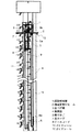
本実施形態の工事用エレベータは、図1に示すように、機械室受けビーム2を介して所定階床の建屋梁10に支持される仮設機械室1と、この仮設機械室1に設置された巻上げ機3と、この巻上げ機3より駆動力を伝達され、昇降路4内をガイドレール11、12によりそれぞれガイドされ釣瓶式に昇降する乗りかご5およびつり合いおもり6と、仮設機械室1から送り出されるとともに乗りかご5上部に設置されたかご上プーリ5aと巻上げ機シーブ3aとつり合いおもり6の上部に設置されたつり合いおもりプーリ6aとを巻回したあと仮設機械室1に固定されるよう張設される主ロープ7と、乗りかご5と仮設機械室1との間に張設され電力および制御信号を伝送するテールコード8と、乗りかご5とつり合いおもり6との間に張設されるコンペンチェーン9と、仮設機械室1内に設置され制御信号を発信するとともにエレベータ全体の走行制御を行なう制御盤13とを有している。
【0032】
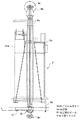
仮設機械室1は、図2に示すように上部機械室1aおよび下部機械室1bと、昇降路4内に所定間隔をおいて立設され、上部機械室1aおよび下部機械室1bを連結する一対の連結柱1cとから構成されている。上部機械室1aには、主ロープ7が送出し可能に巻回されるロープ送出し装置71と、テールコード8が送出し可能に巻回されるテールコード送出し装置81とが設置されている。一方、下部機械室1bに、主ロープ7が巻掛けられる巻上げ機3と、テールコード8を介して制御信号を発信するとともにエレベータ全体の走行制御を行なう制御盤13と、乗りかご5の昇降速度が過速度となったことを検出するガバナ装置14と、ロープ送出し装置71から送り出された主ロープ7を保持するロープ固定装置72とが設置されている。連結柱1cの上下部には、それぞれ乗りかご用ガイドレール11に係合し、仮設機械室1をガイドする上部ガイド体15a、下部ガイド体15bが設けられている。また、図6に示すように、仮設機械室1の底面には機械室受けビーム2の出し入れをガイドする機械室ビームガイド2aが設けられている。
【0033】
上部機械室1aは、連結柱1cの上端部に連結される天井部101aと、この天井部101aの四隅よりそれぞれ垂下される複数本の上柱103aと、これらの上柱103aの下端間に設けられ、連結柱1cの中間部に連結される上連結梁102aとからなっている。天井部101aには、揚重用フック16が取付けられ、この揚重用フック16に、機械室内機器である巻上げ機3、制御盤13、ガバナ装置14、およびロープ固定装置72のうちの少なくとも1つを解体・搬出するための図示しない揚重装置が装着可能である。
【0034】
下部機械室1bは、連結柱1cの下端部に連結される床部101bと、この床部101bの四隅にそれぞれ立設される複数本の下柱103bと、これらの下柱103bの上端間に設けられるとともに連結柱1cおよび上連結梁102aに連結される下連結梁102bとからなっている。図3に示すように、床101bの端部に張り出し床104bが着脱可能に設けられており、この張り出し床104bは対向する昇降路4壁面に向けて張り出され、ガイドレール11の立設方向とほぼ直交する床面を形成している。
【0035】
乗りかご5は、図7、図8に示すように、枠体5b上に装着され、主ロープ7が巻回されるかご上プーリ5aを有し、枠体5bの上下端に、乗りかご用ガイドレール11と係合して乗りかご5を案内するかご走行案内体5dが設けられている。乗りかご5の底部には、かご受けビーム51が挿入され、かご受けビーム51をガイドしその落下を防止するかごビームガイド5cが設けられており、かご受けビーム51は、建屋梁10間に設けられ、乗りかご5を支持するようになっている。乗りかご5の天井部5eの上部には、図示しない長物の建築資材を収納し運搬できる上部トランク51aが設けられている。
【0036】
次に、工事用エレベータの据付方法を図9から図12を用いて説明する。すなわち、図9に示す昇降路4の頂部に、昇降路4内の浸水を防ぐ止水板17が設けられ、各階床乗場に、昇降路4内への落下を防ぐ養生板18が設けられている。この状態で、まず止水板17および養生板18を足場として、乗りかご用ガイドレール11およびつり合いおもり用ガイドレール12を昇降路4の全行程に立設するとともに、出入口装置19を各階床乗場に据え付ける。
【0037】
次に、図10に示すように、止水板17および養生板18を図示しないタワークレーン等を用いて撤去した後、図11に示すようにつり合いおもり6をタワークレーン等を用いて吊持し、ガイドレール12により案内させながら昇降路4底部まで吊下ろし載置する。次に乗りかご5を同様に吊持して昇降路4内に吊下ろし、乗りかご5を運行するサービス階のうちの最上階(例えば6階)に前述したかご受けビーム51を用いて乗りかご5を載置した後、上記のサービス階の上方階(ここでは8階)に機械室受けビーム2を用いて仮設機械室1を吊下ろして載置する。このとき、タワークレーン等揚重設備の能力に制限がある場合、仮設機械室1を上部機械室1a、下部機械室1bに2分割して別々に二度に分けて吊上げて昇降路4内に搬入する。
【0038】
次に、仮設機械室1内のロープ固定装置72による固定を解除し、ロープ送出し装置71から主ロープ7を昇降路4下方に向けてそのロープ端を送出し、かご上プーリ5aに巻回させ、巻上げ機シーブ3aに巻回させ、つり合いおもり6のシーブ6aに巻回させた後、仮設機械室1の床部101bに主ロープ7のロープ端を連結し、その送出しを抑制するようロープ固定装置72で主ロープ7を固定することにより主ロープ7のローピング作業を行なう。
【0039】
次に、テールコード送出し装置81から乗りかご5の昇降に必要な行程分(ここでは6階床分)のテールコード8を引出し、その引出した先端を乗りかご5に連結する。このテールコード8の他端は制御盤13および図示しない電源に連結されており、前記の連結を行なうことにより乗りかご5と仮設機械室1間で電力および制御信号の伝達が可能となる。そして、乗りかご5に設けた図示しないガバナロープ送出し装置からガバナロープを送出し、仮設機械室1に設けたガバナ装置14と昇降路4底部に設けた図示しないガバナプーリとに巻回させることに応じて、乗りかご5の過速度も検出可能となる。
【0040】
最後に、かご受けビーム51をかごビームガイド5cから抜き取り、図12に示すように止水板17を昇降路4の頂部(ここでは10階)に設置すれば、乗りかご5は6階から地下階(B1階)の間で運行サービスが可能となる。
【0041】
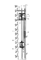
次に、本実施形態に係る昇降階を上方へ拡大(以下ステップアップと称する)する際の作業方法を図13〜図15を用いて説明する。すなわち、まず図13に示すように止水板17上に、ガイドレール11、12をユニット化したレールユニット91をタワークレーン等を用いて吊下ろした後、止水板17上に足場20を組上げる。この足場20を利用して、先程吊下ろした乗りかご用ガイドレール11およびつり合いおもり用ガイドレール12を、建築完了した建屋分(ここでは14階床まで)立設固定した後、足場20および止水板17を昇降路4内から撤去する。
【0042】
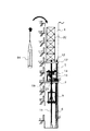
次に、ロープ固定装置72の固定状態を解除してから、仮設機械室1の底部と乗りかご5とをチェーンブロック21にて連結して、止水板17が設置可能となる階床(ここでは12階)まで吊り上げ、前記の据付時と同様に、図14に示すように機械室受けビーム2とかご受けビーム51とを用いて仮設機械室1および乗りかご5を載置する。この際、ロープ固定装置72はその固定を解除されているため、主ロープ7はロープ送出し装置71から送り出され、つり合いおもり6と仮設機械室1間のロープ長さが伸長していくこととなる。同時に、ガバナロープ送出し装置からもガバナロープが送り出され、上方へ拡大した分が新たに張設される。
【0043】
そして前述した据付時と同様に、テールコード8を昇降工程の拡大分(ここでは2階床分)送出し、チェーンブロック21による連結を解き、かご受けビーム51を抜き取り、ロープ固定装置72による主ロープ7の固定を行い、図15に示すように止水板17を昇降路4の頂部に設置すればステップアップ作業は終了し、新たに10階から地下階(B1階)までの乗りかご5の運行サービスが可能である。なお、この工事用エレベータが据え付けられる建屋における最大サービス階床が25階床であれば、図1に示したようにステップアップすれば22階からB1階まで乗りかご5の運行サービスが可能である。
【0044】
このように構成した本実施形態の工事用エレベータでは、下部機械室1bに必要に応じて張出し可能な張出し床104bを設けてあるため、仮設機械室1内の制御盤13、巻上げ機3等の点検保守をする際にそのスペースを確保可能であり作業効率を向上できる。
【0045】
また、本実施形態の工事用エレベータでは、仮設機械室1の連結柱1cによる連結を解いて上連結梁102aと下連結梁102bの連結を解けば、図4、図5に示すように上部機械室1a、下部機械室1bに2分割可能であるので、工場から建築現場までの運搬用トラックに載せた際に道路交通法上の高さ制限以下にすることが可能である。また、上部機械室1a、下部機械室1bの2分割で軽量となるため、建築現場のタワークレーン等の揚重能力の制約を受けることなく昇降路4内に搬入でき、さらに、搬入や移設に際して安全にかつ効率良く位置決め作業ができる。
【0046】
また、本実施形態の工事用エレベータでは、仮設機械室1内に揚重用フック16を設けたため、このフック16に揚重装置を装着すれば、完成した昇降路4内から仮設機械室1内の機器を効率良く解体・搬出できる。そして、仮設機械室1に梁102a、102bおよび柱103a、103bを設けた構造としたことから、最終的に制御盤13、巻上げ機3等を解体・搬出するための揚重装置を仮設機械室1内に設置するための強度を確保でき、さらにその揚重装置を揚重用フック16に装着することにより揚重作業の円滑化が図れる。
【0047】
また、本実施形態の工事用エレベータでは、乗りかご5および仮設機械室1の建屋梁10への載置の際に、それぞれの受けビーム2、51の出し入れをガイドするガイド2a、5cを設けたことから、出し入れ時にビーム2、51を落下させることなく安全に、かつ円滑に効率よく受けビーム2、51の取付・取外し作業を行なうことができる。また、ロープ92を介して図示しないタワークレーンに吊上げられた仮設機械室1の機械室ビームガイド2aに機械室受けビーム2をガイドさせて出し入れすればビームが落下することなく円滑に仮設機械室1を機械室ビームガイド2aを介して建屋梁10へ載置することができる。
【0048】
また、本実施形態の工事用エレベータでは、乗りかご5の天井部5e上に設けた上部トランク51aで長尺物などの建築資材を運搬することにより、その運搬を効率良く行える。
【0049】
なお、前述の据付方法によれば、止水板17および養生板18を設置してある建屋状態においても、これらの止水板17および養生板18を利用して乗りかご用ガイドレール11、つり合いおもり用ガイドレール12および乗場出入口装置19を据え付けることができるため、工事用エレベータを効率良く据え付けることができる。
【0050】
【発明の効果】
以上説明したように、本発明の請求項1に係る発明は、仮設機械室の床面から、乗りかご用ガイドレールが立設される側の昇降路壁面に向けて張出し床が張り出しているので、その張出し床の分だけ仮設機械室内にスペースの余裕ができ、したがって、仮設機械室内の機器の保守・点検が容易になる。
【0051】
また、本発明の請求項2に係る発明は、下部機械室と上部機械室に2分割としてそれぞれに予め機械室内機器を取り付けた状態としたことで道路交通法上の高さ制限にも対応でき、現地での組立も容易に行える。また、一対の連結柱の上下部に設けたガイド体により仮設機械室が乗りかご用ガイドレールに沿って円滑に案内されるのでを精度良く、かつ安全に移設・設置できる。
【0052】
また、本発明の請求項3に係る発明は、仮設機械室の天井部および床部間を連結する複数本の柱や連結梁を設けて一対の連結柱で連結したため、軽量でかつ高剛性を有する機械室構造とすることができる。
【0053】
また、本発明の請求項4に係る発明は、上部機械室の天井部に設けた揚重用フックに揚重装置を装着し、この揚重装置で機械室内機器の解体・搬出を行なうことにより解体・搬出作業を効率良く行なうことができる。
【図面の簡単な説明】
【図1】本発明の一実施形態に係る工事用エレベータの全体構成を示す縦断面図である。
【図2】本実施形態に設けられる仮設機械室の側面図である。
【図3】本実施形態に設けられる下部機械室の平面図である。
【図4】下部機械室の側面図である。
【図5】本実施形態に設けられる上部機械室の側面図である。
【図6】仮設機械室の斜視図である。
【図7】本実施形態に設けられる乗りかごの側面図である。
【図8】乗りかごの斜視図である。
【図9】昇降路内にガイドレールを立設する工程を示す図である。
【図10】昇降路内から止水板および養生板を取り外す工程を示す図である。
【図11】昇降路内に乗りかごおよび仮設機械室を搬入する工程を示す図である。
【図12】仮設機械室を下降させた状態を示す図である。
【図13】ガイドレールを上方へ伸ばす工程を示す図である。
【図14】仮設機械室を上方へ移設した状態を示す図である。
【図15】昇降路頂部に止水板を設置する工程を示す図である。
【符号の説明】
1 仮設機械室
1a 上部機械室
1b 下部機械室
1c 連結柱
2 機械室受けビーム
2a 機械室ビームガイド
3 巻上げ機
4 昇降路
5 乗りかご
5c かごビームガイド
5e 天井部
7 主ロープ
8 テールコード
11 ガイドレール
12 ガイドレール
13 制御盤
14 ガバナ装置
15a 上部ガイド体
15b 下部ガイド体
16 揚重用フック
17 止水板
18 養生板
51 かご受けビーム
51a 上部トランク
71 ロープ送出し装置
72 ロープ固定装置
81 テールコード送出し装置
101a 天井部
101b 床部
102a 上連結梁
102b 下連結梁
103a 上柱
103b 下柱
104b 張出し床[0001]
BACKGROUND OF THE INVENTION
The present invention relates to a construction elevator that sequentially expands a service floor for operating a car by moving a temporary machine room in a hoistway upward according to the progress of construction at a construction site such as a high-rise building. And its installation method.
[0002]
[Prior art]
Conventionally, as disclosed in, for example, JP-A-8-133635 and JP-A-4-243786, a machine room temporarily installed in a hoistway is moved upward in accordance with the progress of building construction work. There has been proposed an elevator for construction that can gradually extend the lifting and lowering process of the car. In such a conventional construction elevator, even if it is a building construction site of a high-rise building, it is possible to transport building materials to the upper floors using elevators and to raise and lower construction workers while the elevator is not completed. The efficiency of building construction can be improved.
[0003]
[Problems to be solved by the invention]
By the way, in the conventional construction elevator described above, the temporary machine room is moved upward in the hoistway according to the progress of the building work, so that equipment in the temporary machine room, that is, a control panel, a hoisting machine, and a rope are sent out. It is necessary to arrange all the devices and the like in a temporary machine room that is narrower than the hoistway dimension. Therefore, there is no room in the temporary machine room and it is difficult to maintain and inspect equipment in the temporary machine room.
[0004]
Moreover, in order to arrange the equipment in the temporary machine room described above, it is necessary to increase the height dimension of the temporary machine room. However, if the height dimension of the temporary machine room is increased, transport from the factory to the construction site is required. When it is placed on a truck, it is difficult to make it less than the height limit under the Road Traffic Law, so that the troublesome work of dividing and transporting the temporary machine room and assembling it on site has occurred.
[0005]
Moreover, since the temporary machine room mentioned above is carried into the hoistway by a lifting equipment such as a tower crane at a construction site, it is necessary to reduce the weight as much as possible so as not to be restricted by this lifting capacity, In order to install the lifting equipment for disassembling and carrying out equipment such as a hoisting machine in the temporary machine room, the strength of the temporary machine room itself was necessary, but this point was not fully considered.
[0009]
The present invention has been made in view of such circumstances in the prior art, and a first object of the present invention is to provide a space in the temporary machine room, and to perform maintenance / inspection work for equipment in the temporary machine room. It is to provide an elevator for construction that can be easily performed.
[0010]
The second purpose is to provide a construction elevator that is light in the temporary machine room, can be positioned safely and efficiently during loading and moving, and can be easily transported by truck and easily assembled on site. There is to do.
[0011]
A third object of the present invention is to provide a construction elevator that can efficiently dismantle and carry out equipment in the temporary machine room from the completed hoistway.
[0015]
[Means for Solving the Problems]
In order to achieve the first object, the invention according to
[0016]
In the invention according to
[0017]
In order to achieve the second object, an invention according to
[0018]
In the invention according to
[0019]
In order to achieve the second object, the invention according to
[0020]
In the invention according to
[0021]
In order to achieve the third object, the invention according to
[0022]
In the invention according to
[0029]
DETAILED DESCRIPTION OF THE INVENTION
Hereinafter, embodiments of the present invention will be described with reference to the drawings.
[0030]
FIG. 1 is a longitudinal sectional view showing the overall construction of a construction elevator according to an embodiment of the present invention, FIG. 2 is a side view of a temporary machine room provided in the present embodiment, and FIG. 3 is a lower machine provided in the present embodiment. 4 is a side view of the lower machine room, FIG. 5 is a side view of the upper machine room provided in the present embodiment, FIG. 6 is a perspective view of the temporary machine room, and FIG. 7 is provided in the present embodiment. FIG. 8 is a perspective view of the car, FIG. 9 is a diagram showing a process of erecting a guide rail in the hoistway, and FIG. 10 is a process of removing the water stop plate and the curing board from the hoistway. FIG. 11 is a diagram showing a process of carrying a car and a temporary machine room into the hoistway, FIG. 12 is a diagram showing a state where the temporary machine room is lowered, and FIG. 13 is a process of extending the guide rail upward. FIG. 14 is a diagram showing a state where the temporary machine room is moved upward, and FIG. It illustrates a step of installing a water stop plate on the front top.
[0031]
As shown in FIG. 1, the construction elevator according to the present embodiment is installed in a
[0032]
As shown in FIG. 2, the
[0033]
The
[0034]
The
[0035]
As shown in FIGS. 7 and 8, the
[0036]
Will now be described with reference to FIG. 12 a method of installation engineering matters elevator from FIG. That is, a
[0037]
Next, as shown in FIG. 10, after removing the
[0038]
Next, the fixing by the
[0039]
Next, the
[0040]
Finally, if the
[0041]
Next, an operation method when the elevator floor according to the present embodiment is expanded upward (hereinafter referred to as “step-up”) will be described with reference to FIGS. 13 to 15. That is, first, as shown in FIG. 13, a
[0042]
Next, after the fixed state of the
[0043]
Then, as in the case of the above-mentioned installation, the
[0044]
In the construction elevator according to the present embodiment configured as described above, the
[0045]
Further, in the construction elevator according to the present embodiment, if the connection of the
[0046]
In the construction elevator according to the present embodiment, the lifting
[0047]
In the construction elevator according to the present embodiment, guides 2a and 5c are provided for guiding the receiving
[0048]
In the construction elevator according to the present embodiment, building materials such as long objects can be efficiently transported by the
[0049]
In addition, according to the above-mentioned installation method, even in the building state in which the
[0050]
【The invention's effect】
As described above, in the invention according to
[0051]
Further, the invention according to
[0052]
In the invention according to
[0053]
In the invention according to
[Brief description of the drawings]
FIG. 1 is a longitudinal sectional view showing an overall configuration of a construction elevator according to an embodiment of the present invention.
FIG. 2 is a side view of a temporary machine room provided in the present embodiment.
FIG. 3 is a plan view of a lower machine room provided in the present embodiment.
FIG. 4 is a side view of the lower machine room.
FIG. 5 is a side view of an upper machine room provided in the present embodiment.
FIG. 6 is a perspective view of a temporary machine room.
FIG. 7 is a side view of a car provided in the present embodiment.
FIG. 8 is a perspective view of a car.
FIG. 9 is a diagram showing a step of erecting a guide rail in the hoistway.
FIG. 10 is a diagram showing a process of removing the water stop plate and the curing plate from the hoistway.
FIG. 11 is a diagram showing a process of carrying a car and a temporary machine room into the hoistway.
FIG. 12 is a view showing a state where the temporary machine room is lowered.
FIG. 13 is a diagram showing a step of extending the guide rail upward.
FIG. 14 is a diagram showing a state where the temporary machine room is moved upward.
FIG. 15 is a diagram showing a process of installing a water stop plate at the top of the hoistway.
[Explanation of symbols]
DESCRIPTION OF
Claims (4)
前記仮設機械室の床面に、前記乗りかご用ガイドレールが立設される側の昇降路壁面に向けて張り出され、前記ガイドレールの立設方向とほぼ直交する床面を形成する張出し床を着脱可能に備えたことを特徴とする工事用エレベータ。For a car and a counterweight provided in a hoistway of a building under construction so as to be movable up and down, and for a car guide rail and a counterweight standing in the hoistway and guiding the car and the counterweight respectively. and the guide rail, is accommodated in the hoistway, the temporary machine room is moved upwards are sequentially guided to the car guide rails in accordance with the construction of the building, provided in the temporary machine room, the ride For a construction work that has a hoisting machine on which a main rope for raising and lowering the counterweight in a fishing bottle type is wound, and that the service floor for operating the car is expanded upward with the relocation of the temporary machine room In the elevator
An overhanging floor is formed on the floor surface of the temporary machine room so as to protrude toward the hoistway wall on the side where the guide rail for the car is erected, and forms a floor surface substantially orthogonal to the direction in which the guide rail is erected. Elevator for construction, characterized in that it is detachable.
前記仮設機械室が、
前記巻上げ機および乗りかごの昇降を制御する制御盤、前記乗りかごの異常速度を検出するガバナ装置、および前記主ロープを保持するロープ固定装置とが予め組込まれるとともに、前記仮設機械室の床面に、前記乗りかご用ガイドレールが立設される側の昇降路壁面に向けて張り出され、前記乗りかご用ガイドレールの立設方向とほぼ直交する床面を形成する着脱可能な張出し床を有する下部機械室と、
前記主ロープを送り出すロープ送出し装置、および前記制御盤と乗りかごを接続するテールコードを送り出すテールコード送出し装置が予め組込まれる上部機械室と、
上下部にそれぞれ前記乗りかご用ガイドレールに係合するガイド体を有し、前記上部機械室および下部機械室を連結する一対の連結柱とから構成されたことを特徴とする工事用エレベータ。For a car and a counterweight provided in a hoistway of a building under construction so as to be movable up and down, and for a car guide rail and a counterweight standing in the hoistway and guiding the car and the counterweight respectively. and the guide rail, is accommodated in the hoistway, the temporary machine room is moved upwards are sequentially guided to the car guide rails in accordance with the construction of the building, provided in the temporary machine room, the ride For a construction work that has a hoisting machine on which a main rope for raising and lowering the counterweight in a fishing bottle type is wound, and that the service floor for operating the car is expanded upward with the relocation of the temporary machine room In the elevator
The temporary machine room is
A control panel for controlling the hoisting and lifting of the car, a governor device for detecting an abnormal speed of the car, and a rope fixing device for holding the main rope are incorporated in advance, and the floor surface of the temporary machine room A detachable extended floor that protrudes toward the hoistway wall on the side where the guide rail for the car is erected and forms a floor surface that is substantially orthogonal to the direction in which the guide rail for the car is erected A lower machine room having,
An upper machine chamber in which a rope feeding device for feeding out the main rope, and a tail cord feeding device for sending out a tail cord for connecting the control panel and a car in advance,
A construction elevator characterized in that upper and lower portions each have a guide body that engages with the guide rail for the car, and is composed of a pair of connecting columns that connect the upper machine room and the lower machine room.
前記仮設機械室は、前記昇降路内に所定間隔をおいて立設される一対の連結柱と、
これらの連結柱の下端部に連結される床部、この床部の端部にそれぞれ立設される複数本の下柱、およびこれらの下柱の上端間に設けられるとともに前記連結柱に連結される下連結梁とを有する下部機械室と、
前記連結柱の上端部に連結される天井部と、この天井部の端部よりそれぞれ垂下される複数本の上柱、およびこれらの上柱の下端間に設けられ、前記連結柱および下連結梁に連結される上連結梁を有する上部機械室とから構成されたことを特徴とする工事用エレベータ。The construction elevator according to claim 1,
The temporary machine room has a pair of connecting pillars standing at a predetermined interval in the hoistway,
A floor portion connected to the lower end portions of these connecting pillars, a plurality of lower pillars standing on the end portions of the floor portions, and provided between the upper ends of these lower pillars and connected to the connecting pillars. A lower machine room having a lower connecting beam,
A ceiling portion connected to an upper end portion of the connection column; a plurality of upper columns respectively suspended from the end portion of the ceiling portion; and the connection column and the lower connection beam provided between lower ends of the upper columns. And an upper machine room having an upper connecting beam connected to the elevator.
前記上部機械室の天井部に、前記巻上げ機、制御盤、ガバナ装置およびロープ固定装置のうちの少なくとも1つを解体・搬出するための揚重用フックを備えたことを特徴とする工事用エレベータ。In the construction elevator according to claim 2,
An elevator for construction comprising a lifting hook for disassembling and carrying out at least one of the hoisting machine, the control panel, the governor device, and the rope fixing device on the ceiling of the upper machine room.
Priority Applications (1)
| Application Number | Priority Date | Filing Date | Title |
|---|---|---|---|
| JP2000102489A JP3920527B2 (en) | 2000-04-04 | 2000-04-04 | Elevator for construction |
Applications Claiming Priority (1)
| Application Number | Priority Date | Filing Date | Title |
|---|---|---|---|
| JP2000102489A JP3920527B2 (en) | 2000-04-04 | 2000-04-04 | Elevator for construction |
Publications (2)
| Publication Number | Publication Date |
|---|---|
| JP2001287881A JP2001287881A (en) | 2001-10-16 |
| JP3920527B2 true JP3920527B2 (en) | 2007-05-30 |
Family
ID=18616361
Family Applications (1)
| Application Number | Title | Priority Date | Filing Date |
|---|---|---|---|
| JP2000102489A Expired - Lifetime JP3920527B2 (en) | 2000-04-04 | 2000-04-04 | Elevator for construction |
Country Status (1)
| Country | Link |
|---|---|
| JP (1) | JP3920527B2 (en) |
Families Citing this family (3)
| Publication number | Priority date | Publication date | Assignee | Title |
|---|---|---|---|---|
| JP5137013B2 (en) * | 2007-12-27 | 2013-02-06 | 東芝エレベータ株式会社 | Elevator by rise-up method |
| JP5799546B2 (en) * | 2011-03-30 | 2015-10-28 | 株式会社大林組 | Elevator, its installation method and elevator installation method |
| EP4234471A1 (en) | 2020-10-20 | 2023-08-30 | Hitachi, Ltd. | Construction elevator and method for extending main rope of construction elevator |
Family Cites Families (7)
| Publication number | Priority date | Publication date | Assignee | Title |
|---|---|---|---|---|
| JPS6026051Y2 (en) * | 1980-12-24 | 1985-08-05 | フジテツク株式会社 | Construction elevator machine room |
| JP2862681B2 (en) * | 1991-01-25 | 1999-03-03 | 株式会社東芝 | Elevator installation method for construction using this equipment |
| JPH0776472A (en) * | 1993-09-08 | 1995-03-20 | Hitachi Building Syst Eng & Service Co Ltd | Method for installing elevator |
| JPH08133635A (en) * | 1994-11-02 | 1996-05-28 | Otis Elevator Co | Temporary machine room for jump-up elevator |
| JPH08175776A (en) * | 1994-12-26 | 1996-07-09 | Toshiba Elevator Technos Kk | Machine room of elevator |
| JPH08324932A (en) * | 1995-06-01 | 1996-12-10 | Otis Elevator Co | Car of elevator |
| JP3579816B2 (en) * | 1997-11-25 | 2004-10-20 | 清水建設株式会社 | Multipurpose stage for building frame |
-
2000
- 2000-04-04 JP JP2000102489A patent/JP3920527B2/en not_active Expired - Lifetime
Also Published As
| Publication number | Publication date |
|---|---|
| JP2001287881A (en) | 2001-10-16 |
Similar Documents
| Publication | Publication Date | Title |
|---|---|---|
| US7559409B2 (en) | Procedure and apparatus for the installation of an elevator | |
| CA2002158C (en) | Elevator erection system using pit storage and roof hoist | |
| US20090223751A1 (en) | Method and apparatus for installing an elevator without machine room during construction of a building, and use of a hoisting machine | |
| JPH03264482A (en) | Method for installing elevator | |
| JPWO2020035933A1 (en) | How to apply elevator head extension technology | |
| WO2020142001A1 (en) | A moveable platform | |
| JP3920527B2 (en) | Elevator for construction | |
| JP3844944B2 (en) | Demolition method of construction elevator | |
| KR101976724B1 (en) | Method for installing elevator guide rails without a machine room | |
| JPH09278325A (en) | Construction work elevator lifting method and construction work elevator device | |
| JP5150313B2 (en) | Three-dimensional parking device in void and its construction method | |
| JP2008063873A (en) | Transfer mechanism of ceiling and execution method | |
| JPH05262475A (en) | Installation method of elevator | |
| JPH021066B2 (en) | ||
| JPH05201648A (en) | Installation of elevator | |
| JP3253441B2 (en) | Elevator installation method | |
| JPH01127585A (en) | Method of installation construction of elevator | |
| JP2612258B2 (en) | Elevator installation construction method | |
| JPH05113026A (en) | Temporary scaffold structure | |
| JPH07315740A (en) | Carrying out method for escalator truss | |
| JPH10140839A (en) | Device for vertically hoisting form material and pipe support | |
| JP2011020803A (en) | Renewal method of elevator | |
| JP4454744B2 (en) | Temporary elevator device | |
| WO2023160818A1 (en) | An elevator construction arrangement and a method | |
| JPH0776473A (en) | Apparatus and method for installing elevator |
Legal Events
| Date | Code | Title | Description |
|---|---|---|---|
| A131 | Notification of reasons for refusal |
Free format text: JAPANESE INTERMEDIATE CODE: A131 Effective date: 20060509 |
|
| A521 | Written amendment |
Free format text: JAPANESE INTERMEDIATE CODE: A523 Effective date: 20060705 |
|
| TRDD | Decision of grant or rejection written | ||
| A01 | Written decision to grant a patent or to grant a registration (utility model) |
Free format text: JAPANESE INTERMEDIATE CODE: A01 Effective date: 20070206 |
|
| A61 | First payment of annual fees (during grant procedure) |
Free format text: JAPANESE INTERMEDIATE CODE: A61 Effective date: 20070215 |
|
| R150 | Certificate of patent or registration of utility model |
Free format text: JAPANESE INTERMEDIATE CODE: R150 Ref document number: 3920527 Country of ref document: JP Free format text: JAPANESE INTERMEDIATE CODE: R150 |
|
| FPAY | Renewal fee payment (event date is renewal date of database) |
Free format text: PAYMENT UNTIL: 20100223 Year of fee payment: 3 |
|
| FPAY | Renewal fee payment (event date is renewal date of database) |
Free format text: PAYMENT UNTIL: 20130223 Year of fee payment: 6 |
|
| FPAY | Renewal fee payment (event date is renewal date of database) |
Free format text: PAYMENT UNTIL: 20130223 Year of fee payment: 6 |
|
| FPAY | Renewal fee payment (event date is renewal date of database) |
Free format text: PAYMENT UNTIL: 20150223 Year of fee payment: 8 |
|
| S531 | Written request for registration of change of domicile |
Free format text: JAPANESE INTERMEDIATE CODE: R313531 |
|
| R350 | Written notification of registration of transfer |
Free format text: JAPANESE INTERMEDIATE CODE: R350 |
|
| EXPY | Cancellation because of completion of term |