JP3701882B2 - Paste applicator - Google Patents
Paste applicator Download PDFInfo
- Publication number
- JP3701882B2 JP3701882B2 JP2001157495A JP2001157495A JP3701882B2 JP 3701882 B2 JP3701882 B2 JP 3701882B2 JP 2001157495 A JP2001157495 A JP 2001157495A JP 2001157495 A JP2001157495 A JP 2001157495A JP 3701882 B2 JP3701882 B2 JP 3701882B2
- Authority
- JP
- Japan
- Prior art keywords
- paste
- frame
- coating
- substrate
- heads
- Prior art date
- Legal status (The legal status is an assumption and is not a legal conclusion. Google has not performed a legal analysis and makes no representation as to the accuracy of the status listed.)
- Expired - Lifetime
Links
Images


Landscapes
- Materials For Photolithography (AREA)
- Coating Apparatus (AREA)
- Linear Motors (AREA)
Description
【0001】
【発明の属する技術分野】
本発明は、フラットパネルやプリント基板或いは半導体組立の製造過程などで用い、ノズルの吐出口に対向するように基板をテ−ブル上に載置し、ペースト収納筒に充填されたペーストをこのノズルの吐出口から基板上に吐出させながら基板とノズルの相対位置関係を変化させ、基板上に所望形状のペーストパタ−ンを塗布するペースト塗布機に係り、特に、ノズルを含む塗布ヘッドの駆動機構に関する。
【0002】
【従来の技術】
テーブル上に該基板における上面と平行な一方向に移動し得るようにフレームを設け、ペースト収納筒と基板に吐出口が対向するノズルを備えた塗布ヘッドをフレームの伸延方向に移動し得るように設け、フレームと塗布ヘッドを基板上の所望の位置に移動させてノズルの吐出口より該基板上の所望の位置にぺーストを塗布させるペースト塗布機があり、塗布ヘッドはボールネジを用いたサーボモータで駆動されている(特開2000―93866号公報参照)。
【0003】
【発明が解決しようとする課題】
この場合、複数の塗布ヘッドを設け、それらのノズルから夫々ペーストを所望のパターンで基板上に同時に塗布しようとすると、各塗布ヘッド毎にボールネジやサーボモータを必要とし、構造が複雑になり、また、装置重量が増加するが、さらに、それだけでなく、各ボールネジは稼動中の温度上昇に起因して熱膨張差を生じ、各塗布ヘッドの正確な位置制御が困難になるという問題があった。また、基板上に存在する複数の可動部での発塵があり、基板が汚染するという問題もあった。
【0004】
本発明の目的は、簡単な構成で軽重量化を図ることができ、基板上に正確に所望のパターンでペーストを塗布することを可能とし、さらに、基板の汚染が生じないペースト塗布機を提供することにある。
【0005】
本発明の他の目的は、簡単な構成であっても、基板上に安定して高速に、かつ正確な所望形状のパターンでペーストを塗布することを可能としたペースト塗布機を提供することにある。
【0006】
【課題を解決するための手段】
上記目的を達成するために、本発明は、架台に設けられたテーブル上に基板を搭載し、基板上に所望形状のペーストパターンを塗布描画するペースト塗布機において、架台に、第1のリニアスケールを第1の方向に伸延するように設けるとともに、架台上で第1の方向とは異なる第2の方向に伸延し、かつ第1のリニアスケールを検出する第1の検出器と第2の方向に伸延した第2のリニアスケールとが設けられ、リニアモータの駆動により、テーブルに搭載された基板のペーストパターンが塗布描画される面に平行な面内で架台上を第1の方向に移動可能なフレームと、フレームに複数個配列されて、夫々が、第2のリニアスケールを検出する第2の検出器とともに、ペースト収納筒とペースト収納筒に充填されたペーストを吐出するペースト吐出口を有するノズルが設けられ、リニアモータの駆動により、フレームに沿って移動可能な塗布ヘッドと、第1,第2の検出器によるフレームと夫々の塗布ヘッドとの位置検出結果に応じてフレームと夫々の塗布ヘッドとのリニアモータを駆動し、フレームや複数の塗布ヘッド夫々の位置制御を行なうことにより、ペースト吐出口がテーブルに搭載された基板に対向する範囲内で、架台に対してフレームを移動させ、かつフレームに対して複数の塗布ヘッドを移動させながら、複数の塗布ヘッドのペースト吐出口からペーストを吐出させる制御をする制御手段とを設け、複数の塗布ヘッドによって基板上に所望形状のペーストパターンを複数塗布描画する構成とする。
【0007】
そして、複数の塗布ヘッド夫々のリニアモータは、フレームに、その伸延方向に沿って、設けられたマグネットと、マグネットに対向して塗布ヘッドに設けられた電機子コイルとからなる構成とするものである。
【0008】
上記他の目的を達成するために、本発明は、上記構成において、制御手段は、フレームの伸延方向に沿って複数の塗布ヘッドを移動させた場合、隣合う2個の塗布ヘッドが予め設定された相互の干渉範囲内に入るときには、これら2個のうちの一方の塗布ヘッドを停止させて他方の塗布ヘッドを移動させ、他方の塗布ヘッドの移動終了後、一方の塗布ヘッドを移動させるように制御するものである。
【0009】
また、フレームとしては、互いに平行な配置関係で2個以上設けられ、制御手段は、これらフレームを移動させた場合、隣合う2つのフレームが予め設定された相互の干渉範囲内に入るときには、これら2個のうちの一方のフレームを停止させて他方のフレームを移動させ、他方のフレームの移動終了後、一方のフレームを移動させるように制御することものである。
【0010】
【発明の実施の形態】
以下、本発明の実施形態を図面を用いて説明する。
図1は本発明ペースト塗布機の一実施形態を示す斜視図であって、1は架台、2A,2Bはフレーム、3A,3Bは固定部、4A〜4Dは可動部、5A〜5Dは塗布ヘッド、6は基板保持盤、7はθ軸回転テ−ブル、8は基板、9は主制御部、10は副制御部、11はモニタ、12はキ−ボ−ドである。
【0011】
同図において、架台1上には、固定部3A,3Bと可動部4A〜4Dとフレーム2A,2BとからなるX軸駆動機構が設けられている。固定部3A,3Bは架台1上にX軸方向に沿って固定されており、固定部3A上を2つの可動部4A,4Cが、固定部3B上を2つの可動部4B,4Dが夫々移動可能に設けられている。そして、可動部4Aと可動部4Bとにまたがって(即ち、Y軸方向に沿って)フレーム2Aが、また、可動部4Cと可動部4Dとにまたがって(即ち、Y軸方向に沿って)フレーム2Bが夫々設けられている。
【0012】
フレーム2Aには、2つの塗布ヘッド5A,5Bがこのフレーム2Aの長手方向(即ち、Y方向)に移動可能に設けられており、また、フレーム2Bには、2つの塗布ヘッド5C,5Dがこのフレーム2Bの長手方向(即ち、Y方向)に移動可能に設けられている。
【0013】
架台1上、X軸駆動機構の固定部3A,3B間には、基板保持盤6を搭載し、かつθ軸方向に回転可能なθ軸回転テーブル7が設けられ、この基板保持盤6上に基板8が吸着保持(載置)される。また、架台1には、モニタ11やキーボード12が設けられ、主制御部9や副制御部10などが内蔵されている。
【0014】
図2は図1におけるX軸駆動機構の可動部4Aの部分を示す図であって、同図(a)はこの部分をY軸方向から見た側面図、同図(b)はこの部分をX軸方向から見た図である。なお、3a1はマグネット、3a2,3a3はリニアガイド、3a4はリニアスケール、4a1は電機子コイル、4a2は検出部であり、図1に対応する部分には同一符号を付けている。
【0015】
図2(a),(b)において、X軸駆動機構の固定部3Aには、X軸方向(紙面に垂直な方向)に並行したマグネット3a1とリニアガイド3a2,3a3とリニアスケール3a4とが設けられ、可動部4Aには、固定部3Aのマグネット3a1とでリニアモータを構成する電機子コイル4a1とリニアスケール3a4の検出部4a2とが設けられている。可動部4Aは、リニアモータの駆動力により、リニアガイド3a2,3a3にX軸方向に移動する。
【0016】
図1における固定部3Bもこの固定部3Aと同様の構成をなし、また、可動部4Bも可動部4Aと同じ構成をなしており、可動部4Aの検出部4a2が検出した固定部3Aのリニアスケール3a4の検出結果と可動部4Bの検出部が検出した固定部3Bのリニアスケールの検出結果とをもとに、主制御部9が固定部3A,可動部4Aのリニアモータと固定部3B,可動部4Bのリニアモータとを制御することにより、これら検出結果が一致するように可動部4A,4Bの位置制御をして、フレーム2Aの長手方向が精度良く固定部3A,3Bに垂直な方向(即ち、Y軸方向)に一致するようにしている。
【0017】
また、図1における可動部4C,4Dも可動部4a1と同様の構成をなしており、これらの検出部の検出結果に応じて主制御部9が同様のこれら可動部4C,4Dの位置制御を行なう。
【0018】
図3は図1における塗布ヘッドの部分を示す図であって、同図(a)はY方向から見た側面図、同図(b)は斜視図である。なお、2a1はマグネット、2a2〜2a4はリニアガイド、2a5はリニアスケール、5a1は基台、5a2は電機子コイル、5a3は検出部、5A1はZ軸サーボモータ、5A2はZ軸ガイド、5A3はZ軸テ−ブル、5A4は光学式距離計、5A5ペースト収納筒(シリンジ)、5A6は画像認識カメラであり、図1に対応する部分には同一符号を付けている。
【0019】
以下では、塗布ヘッド5Aについて説明するが、他の塗布ヘッド5B〜5Dについても同様である。
【0020】
図3(a),(b)において、フレーム2Aには、塗布ヘッド5Aの(従って、塗布ヘッド5Bの)Y軸駆動機構の固定部(固定側)にもなるものであり、その上面の長手方向(Y軸方向)に沿ってマグネット2a1が、その両脇にそれと平行に2つのリニアガイド2a2,2a3が、さらに、その一方の側面にリニアガイド2a4が、他方の側面にリニアスケール2a5が夫々設けられている。
【0021】
また、塗布ヘッド5Aは、このフレーム2Aをまたがるように配置された基台5a1を有し、この基台5a1に、フレーム2Aのマグネット2a1とともにリニアモータを構成する電機子コイル5a2と、フレーム2Aのリニアスケール2a5の検出部5a3とが設けられている。
【0022】
リニアスケール2a5はフレーム2Aの側面にY軸方向に沿って設けられており、これを検出する検出部5a3は、このリニアスケール2a5に対向して、塗布ヘッド5A、設けられている。この検出部5a3のリニアスケール2a5からの検出結果に基いて主制御部9が塗布ヘッド5Aの電機子コイル5a2とフレーム2Aのマグネット2a1からなるリニアモータを制御することにより、フレーム2A上でのY軸方向の位置制御がなされる。
【0023】
塗布ヘッド5Aの基台5a1には、また、Z軸サーボモータ5A1が設けられ、このZ軸サーボモータ5A1にZ軸ガイド5A2が、さらにこのZ軸ガイド5A2にZ軸テ−ブル5A3が、さらにこのZ軸テ−ブル5A3に距離計5A4が、さらに距離計5A4にペースト収納筒5A5が夫々設けられており、Z軸テ−ブル5A3に、さらに、画像認識カメラ5A6が設けられている。
【0024】
Z軸サーボモータ5A1は、Z軸テ−ブル5A3上に設置された距離計5A4の検出結果に基づく副制御部10(図1)の制御により、Z軸ガイド5A2を介してペースト収納筒5A5や画像認識カメラ5A6をZ軸方向に駆動する。
【0025】
図1に示すような他の塗布ヘッド5B〜5Dについても、これと同様の構成をなすものである。
【0026】
図4は図3(b)における光学式距離計5A4とペースト収納筒5A5の先端に設けられたノズルの位置関係を示する斜視図であって、5A7はノズル支持具、5A8はノズルであり、図3に対応する部分には同一符号を付けている。
【0027】
同図において、ペースト収納筒5A5の下端にノズル支持具5A7が設けられており、その先端部に基板8に向けてペースト吐出口が開いているノズル5A8が取り付けられている。ペースト収納筒5A5とノズル5A8とはノズル支持具5A7で連通しており、ノズル5A8のペースト吐出口は、基板8の上面において、光学式距離計5A4の距離計測光の反射点RAとΔX,ΔYの微差で接近している。
【0028】
この距離計5A4は、ノズル5A8の先端部(ペースト吐出口)から基板8の表面(上面)までの垂直(Z軸方向の)距離を非接触の三角測法で計測する。ノズル5A8の吐出口と距離計5A4での距離計測光の反射点RAのずれΔX,ΔYは、基板8の表面の凹凸によって影響されない程度に設定されているので、ノズル5A8の先端部(ペースト吐出口)から基板8の表面(上面)までの垂直(Z軸方向の)距離には、このずれΔX,ΔYによる殆ど誤差がない。
【0029】
従って、この距離計5A4の計測結果に基いてZ軸サーボモータ5A1を制御し、基板8の表面の凹凸(うねり)に合わせてノズル先端部を上下させることにより、基板8の表面(上面)までの垂直距離(間隔)を常に一定に維持することができる。
【0030】
図1に示す他の塗布ヘッド5B〜5Dについても、これと同様の構成をなすものである。
【0031】
次に、この実施形態における電気及び空圧の制御系統について説明する。
【0032】
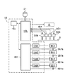
図5は図1における主制御部9の一具体例の構成を示すブロック図であって、4b1〜4d1,5b2〜5d2は電機子コイル、4b2〜4d2,5b3〜5d3は検出器、7aはサーボモータ、7bはθ軸エンコーダ、9aはマイクロコンピュ−タ、9bは外部インターフェース、9cは画像処理装置、9dはモ−タコントロ−ラ、9e1〜9e4はX軸系リニアモータ用アンプ、9e5〜9e8はY軸系リニアモータ用アンプ、9e9、16は正圧源、18は負圧源、17はレギュレータ、19はレギュレータ、20はバルブユニット20であり、図一に対応する部分には同一符号を付けている。
【0033】
同図において、主制御部9は、マイクロコンピュ−タ9aや外部インターフェース9b,画像処理装置9c,モ−タコントロ−ラ9d,X軸系リニアモータ用アンプ9e1〜9e4,Y軸系リニアモータ用アンプ9e5〜9e8及びθ軸回転テーブル7を駆動するサーボモータ7aのアンプ9e9を備えている。なお、サーボモータ7aには、θ軸エンコーダ7bが設けられている。
【0034】
電機子コイル4b1,4c1,4d1は夫々、図1における可動部4B,4C,4Dの電機子コイルであって、図2に示した可動部4Aに対する電機子コイル4a1に相当するものである。電機子コイル5b2,5c2,5d2は夫々、図1における塗布ヘッド5B,5C,5Dの電機子コイルであって、図3に示した可動部5Aに対する電機子コイル5a2に相当するものである。
【0035】
また、検出器4b2,4c2,4d2は夫々、固定部3A,3Bに設けられたリニアスケール(固定部3Aでは、図2(b)に示すリニアスケール3a4)を検出するための可動部4B,4C,4D(図1)での検出器であって、図2(b)に示す可動部4Aでの検出器4a2に対応するものである。検出器5b3,5c3,5d3は夫々、固定部3A,3Bに設けられたリニアスケール(固定部3Aでは、図2(b)に示すリニアスケール3a4)を検出するための塗布ヘッド5B,5C,5D(図1)での検出器であって、図3(a)に示す塗布ヘッド5Aでの検出器5a3に対応するものである。
【0036】
検出器4a2〜4d2,5a3〜5d3の検出出力はモータコントローラ9dに供給され、これら検出出力に応じた駆動信号がモータコントローラ9dが出力され、X軸系リニアモータ用アンプ9e1〜9e4,Y軸系リニアモータ用アンプ9e5〜9e8で増幅された後、電機子コイル4a1〜4d1,5a2〜5d2に供給され、これにより、可動部4A,4Bや塗布ヘッド5A〜5Dのリニアモータが駆動制御されて可動部4A,4Bや塗布ヘッド5A〜5Dが位置制御される。
【0037】
画像処理装置9cは、塗布ヘッド5Aに設けられている画像認識カメラ5A6(図3(b))や塗布ヘッド5B〜5Dに同様に設けられている画像認識カメラで得られた基板8上の映像信号を処理するものであって、これによって得られた映像処理データをもとに、基板8の位置決めなどを行なう。
【0038】
塗布ヘッド5A〜5Dによって基板8上の所望の位置に適宜なパターンでペーストを塗布するには、正圧源16あるいは負圧源18からレギュレータ17,19及びバルブユニット20を介して所望の空気圧を塗布ヘッド5A〜5Dのペースト収納筒(塗布ヘッド5Aでは、図3でのペースト収納5A5)に印加するが、その場合のレギュレータ17,19及びバルブユニット20の制御信号は、外部インターフェース9bから送出される。15はハードディスクである。
【0039】
マイクロコンピュ−タ9aは、図示しないが、主演算部や後述する塗布描画を行なうための処理プログラムを格納したROM,主演算部での処理結果や外部インタ−フェ−ス9bや画像処理装置9cやモ−タコントロ−ラ9dなどからの入力デ−タを格納するRAM,外部インタ−フェ−ス9bや画像処理装置9cやモ−タコントロ−ラ9dなどとデ−タをやりとりする入出力部などを備えている。ハードディスク15には、キーボード12からの描画するペーストパターンを表わすデータなどの入力データやマイクロコンピュータ9aの処理結果のデータなどが格納される。
【0040】
図6は図1における副制御部10の一具体例を示すブロック図であって、5B1,5C1,5D1は塗布ヘッド5B,5C,5DのZ軸サーボモータ、5B4,5C4,5D4は塗布ヘッド5B,5C,5Dの光学式距離計、5A1a,5B1a,5C1a,5D1aは塗布ヘッド5A,5B,5C,5DのZ軸エンコーダ、10aはマイクロコンピュ−タ、10bは外部インターフェース、10cはモ−タコントロ−ラ、10d1〜10d4は夫々Z軸サーボモータ5A1,5B1,5C1,5D1用のアンプ、21はハードディスクである。
【0041】
同図において、副制御部17は、マイクロコンピュ−タ10aや外部インターフェース10b,モ−タコントロ−ラ10c、Z軸サーボモータ用アンプ10d1〜10d4を備えている。
【0042】
各塗布ヘッド5Aでは、Z軸サーボモータ5A1にZ軸エンコーダ5A1aが設けられており、Z軸サーボモータ5A1の回転量がZ軸エンコーダ5A1aで検出され、その検出出力が外部インタ−フェ−ス10bを介してマイクロコンピュータ10aに供給される。
【0043】
一方、光学式距離計5A4の計測結果が外部インタ−フェ−ス10bを介してマイクロコンピュータ10aに供給され、基板8の塗布面からノズル5A8(図4)までの距離(ノズル高さ)が算出され、規定のノズル高さとなるための駆動信号を生成される。この駆動信号はモータコントローラ10cを介し、Z軸サーボモータ用アンプ10d1で増幅された後、Z軸サーボモータ5A1に供給される。このように、外部インタ−フェ−ス10bを介して光学式距離計5A4の計測結果を得て、Z軸サーボモータ5A1を操作し、図5に示したZ軸テ−ブル5A3を上下させて、図4に示したノズル5A8のZ軸方向の位置制御を行なう。
【0044】
同様にして、他の塗布ヘッド5B〜5Dも、図4に示す塗布ヘッド5Aと同じ構成をなしており、夫々のZ軸サーボモータ5B1〜5D1の回転量が夫々のZ軸エンコーダ5B1a〜5D1aで検出されてモ−タコントロ−ラ10cからマイクロコンピュータ10aに供給される。モ−タコントロ−ラ10cは、外部インタ−フェ−ス10bを介して塗布ヘッド5B〜5Dの光学式距離計5B4〜5D4の計測結果を得て、Z軸サーボモータ5B1〜5D1を操作し、図5に示す塗布ヘッド5AのZ軸テ−ブル5A3に相当するZ軸テーブルを上下させて、それらのノズルのZ軸方向の位置制御を行なう。
【0045】
マイクロコンピュ−タ10aには、図示しないが、主演算部や後述する塗布描画時のノズルの高さ制御を行なうための処理プログラムを格納したROM,主演算部での処理結果や外部インタ−フェ−ス10bやモ−タコントロ−ラ10cなどからの入力デ−タを格納するRAM,外部インタ−フェ−ス10bやモ−タコントロ−ラ10cとデ−タをやりとりする入出力部などを備えている。また、ハードディスク21には、所望のデータが格納される。
【0046】
主制御部9と副制御部10とは以上のように構成されており、X軸方向(図1)に移動可能な可動部4A,4Bとでの各リニアモ−タの電機子コイル4a1〜4dやY軸方向(図1)に移動可能な塗布ヘッド5A〜5Dの各リニアモ−タの電機子コイル5a2〜5d2及びZ軸サーボモータ5A1〜5D1が、主制御部9の外部インタ−フェ−ス9b,10bを介して主制御部9と副制御部10とで連携しており、これにより、キ−ボ−ド12から予め入力されてマイクロコンピュ−タ9aのRAMに格納されているデ−タに基いて、塗布ヘッド5A〜5Dが(従って、それらのノズルが)、基板保持盤6に吸着保持した基板8に対して、X,Y各軸方向に移動し、また、塗布ヘッド5A〜5DのZ軸テ−ブル(塗布ヘッド5Aでは、Z軸テ−ブル5A3(図3))を介して支持されたノズル(塗布ヘッド5Aでは、ノズル5A8(図4))をZ軸方向に任意の距離を移動し、その移動中、ペースト収納筒(塗布ヘッド5aでは、ペースト収納筒5A5(図3))にキ−ボ−ド12から入力されてマイクロコンピュ−タ9aのRAMに格納されているデ−タに基いた正圧レギュレータ17で調節される気圧が継続して印加され、これらノズルの先端のペースト吐出口からペーストが吐出され、基板8に所望のペーストパタ−ンが塗布描画される。
【0047】
そして、かかるペースト塗布動作中では、後述するように、主制御部9(図5)のモータコントローラ9dにより、各リニアモータの電機子4a1〜4d1,5a2〜5d2の位置が予め設定された干渉範囲(塗布ヘッドが近づき過ぎて衝突が生ずる恐れがある塗布ヘッド間の距離範囲)にあるかどうかの監視を常時行なっており、誤った移動指令が入った場合にも、この監視プログラムにより、衝突しないように、塗布処理を停止させることができるようにしている。
【0048】
X軸方向に移動する可動部4A〜4DやY軸方向に移動する塗布ヘッド5A〜5Dのリニアモータは、複数のマグネットを並置してなるものを固定側(固定部3A,3B側やフレーム2A,2B側に設けている。)とし、電機子コイルを可動側(可動部4A〜4D側や塗布ヘッド5A〜5D側に設けられている)として、固定側マグネットを共用する形になっているために、従来のボールネジ駆動で発生していた熱膨張による差を生じるようなことはなく、可動側の電機子コイルへ誤信号が与えられないかぎり、XY軸方向での位置誤差はなく、各塗布ヘッド5A〜5Dの正確な位置制御ができる。また、構成は簡単で、発塵が少ない。そして、固定側のマグネットと可動側の電機子コイルとの間に常に吸引力が働いているので、塗布ヘッドは架台1側に拘束される形式であり、移動に際して振動せず、基板8の上主面(ペーストを塗布する面)にうねりがなければ、基板8の上主面から各塗布ヘッド5A〜5Dのノズルのペースト吐出口までの距離に変動は殆ど発生しない。
【0049】
図7はこの実施形態で基板8上に塗布するペーストパターンの一具体例を示す図であって、PTa〜PTdはペーストパターン、Sa〜SdはペーストパターンPTa〜PTdの塗布開始位置である。
【0050】
この具体例では、図7に示すように、図1に示す4個の塗布ヘッド5A〜5Dにより、基板8上に4個のペーストパターンPTa〜PTdを塗布するものである。これらペーストパターンPTa〜PTdは同一形状であって、塗布開始位置Sa〜Sdから終了位置までの2次元経路データが設定されており、ペーストパターンPTaの塗布開始位置Saは、基板8の中心0を原点として、座標(X1,Y1)に、ペーストパターンPTbの塗布開始位置Sbは、同じく座標(X2,Y2)に、ペーストパターンPTcの塗布開始位置Scは、同じく座標(X3,Y3)に、ペーストパターンPTdの塗布開始位置Sdは、同じく座標(X4,Y4)に夫々位置設定されるものとする。
【0051】
次に、図8により、この実施形態のペーストパターンの塗布描画動作について説明する。
【0052】
図8において、まず、電源を投入し(ステップ100)、装置の初期設定をするステップ(200)。
【0053】
この初期設定では、図1において、サーボモータ7a(図5)を駆動してθ軸回転テーブル7を回転させることにより、基板保持盤6はθ方向に移動させて所定の基準角度に位置決めし、可動部4A,4Bと塗布ヘッド5A〜5Dのリニアモータを駆動することにより、これら塗布ヘッド5A〜5Dを移動させてそれらのノズル先端のペースト吐出口を予め決められた所定の原点位置に設定するとともに、ペーストパタ−ンPTa〜PTdの塗布開始位置から終了位置までの2次元経路デ−タや位置決め用マ−クデ−タ,ペースト塗布高さ(各塗布ヘッド5A〜5Dについての基板8の表面からノズル先端のペースト吐出口までの距離)などの設定を行なう。
【0054】
これらデ−タの入力はキ−ボ−ド12から行ない、各入力デ−タは主制御部9のマイクロコンピュ−タ9a(図5)や副制御部10のマイクロコンピュータ10a(図6)に内蔵のRAMに格納するとともに、それら制御部9,10の外部記憶装置であるハードディスク15,21などの記憶媒体に記憶保管しておく。
【0055】
なお、塗布ヘッド5A,5B,5C,5Dのノズル先端のペースト吐出口のXY座標系での上記原点位置は、図9に示すように、基板8外の所定の位置Ta〜Tdとし、塗布開始前にこれらノズルペーストが垂れても、基板8を汚さないようにする。
【0056】
以上の初期設定(ステップ200)の処理が終了すると、次に、基板8を基板保持盤6上に載置して保持させる(ステップ300)。
【0057】
続いて、基板8の位置決めを行なう(ステップ400)。この処理では、塗布ヘッド5A〜5Dの画像認識カメラ(塗布ヘッド5Aでは、画像認識カメラ5A6(図3))のうちのステップ200で初期設定した任意の画像認識カメラを、基板保持盤6に載置した基板8の位置決め用マ−クを撮影できる位置に位置決めして、この位置決め用マークを撮影する。撮影した位置決め用マ−クの重心位置が主制御装置9(図5)の画像処理で求められて、基板8のθ方向での傾きが検出され、この検出結果に基づいてサ−ボモ−タ7aでθ軸回転テーブル7を駆動することにより、基板8のθ方向の傾きが補正される。また、XY軸方向の誤差分(ΔX1,ΔY1)は後述する開始点移動時に補正されるが、このため、上記位置決め用マークの画像データが、マイクロコンピュ−タ9aのRAMに格納されて保管される。
【0058】
ステップ400の基板8の位置決めが終了すると、次に、ペーストの塗布動作が行なわれる(ステップ500)。これを、図10により説明する。
【0059】
同図において、まず、基板8上に未塗布パターンがあるかどうか(即ち、塗布しなければならないが、未だ塗布描画されていないパターンがあるかどうか)を確認する(ステップ510)。未塗布パターンの有無については、後述する。
【0060】
塗布開始時点では、塗布すべき全てのパターンが未塗布であるから、次の開始点移動工程(ステップ520)に進む。これは、塗布ヘッド5A〜5Dを移動させ、図9に示す上記原点位置Ta〜TdからペーストパターンPTa〜PTdの塗布開始位置Sa〜Sdに塗布ヘッド5A〜5D夫々のノズル先端のペースト吐出口が対向するように、これら塗布ヘッド5A〜5Dを位置決め移動させる処理である。これを図11により説明する。
【0061】
同図において、まず、描画対象とするパターン(ここでは、4個のパターン)が同一形状であることを確認し(ステップ521)、同一パターンであれば、同時に塗布可能なパターンであることを確認する(ステップ522)。
【0062】
同時に塗布可能の判断条件は、塗布開始点位置Sa,Sbが同一のX軸上にあり、かつ塗布開始点位置Sc,Sdが同一のX軸上にあることであり、X1=X2、かつX3=X4が成立するとき、同時に塗布可能とするものである。
【0063】
いずれのパターンも同時に塗布可能であるときには、互いに近接した2以上の塗布開始位置があると、夫々にノズル先端が位置付けられる塗布ヘッド同士やノズル同士が衝突する可能性があるので(このような可能性がある距離範囲を干渉範囲という)、塗布開始位置Sa〜Sdにノズル毎が互いに干渉範囲にあるかどうかの確認を行なう(ステップ523)。
【0064】
図12はX軸方向のかかる干渉範囲を説明する図である。
【0065】
同図において、塗布すべきペーストパターンが図7に示すパターンPTa〜PTdの場合、X軸方向について、パターンPTa,PTbでは、基板8の中心OからX軸方向に距離X1(=X2)だけ離れた位置が塗布開始位置Sa,Sbになる。また、パターンPTc,PTdでは、基板8の中心Oから距離X3(=X4)だけ離れた位置が塗布開始位置Sc,Sdになる。塗布開始時では、塗布ヘッド5A,5B,5C,5Dのノズルが夫々、これら塗布開始位置Sa,Sb,Sc,Sdに設定されることになる。
【0066】
ここで、これら塗布開始位置Sa,Sb,Sc,Sdから基板中心Oに向かうX軸方向に干渉範囲XCを設定する。ここで、
(X1−XC)-(X3+XC)>0
即ち、
X1−X3−2XC>0
のとき、フレーム2Aでの塗布ヘッド5A,5Bとフレーム2Bでの塗布ヘッド5C,5Dとは、互いに干渉せず、動作可能である。
【0067】
図13はY軸方向の干渉範囲を説明する図である。
【0068】
同図において、図7の示すパターンのPTa〜PTdの場合、Y軸方向について、パターンPTaでは、基板8の中心Oから距離Y1だけ離れた位置が塗布開始位置Saであり、塗布パターンPTbでは、基板8の中心Oから距離Y2だけ離れた位置が塗布開始位置Sb、塗布パターンPTcでは、基板8の中心OからY3離れた位置が塗布開始位置Sc、塗布パターンPTdでは、基板8の中心OからY4離れた位置が塗布開始位置Sdになる。夫々の塗布開始位置から基板中心0に向かう方向に干渉範囲YCを設定する。
【0069】
パターンPTa,PTbでは、
(Y2−YC)−(Y1+YC)>0
即ち、
Y2−Y1−2YC>0
のとき、塗布ヘッド5A,5Bは、互いに干渉せず動作可能である。また、パターンPTc,PTdでは、
(Y4−YC)−(Y3+YC)>0
即ち、
Y4−Y3−2YC>0
のとき、塗布ヘッド5C,5Dは、互いに干渉せず動作可能である。
【0070】
図11のステップ521〜523の全ての条件を満足する(Yesの判定がある)パターンについては、次のステップ525の処理に進むが、これらステップ521〜523のいずれかの条件を満足しないと(Noの判定があると)、全てのパターンを一括同時塗布することは不可能であり、一括塗布不可能な2つのパターンのうちの片方を未塗布パターンとして記憶させておき(ステップ524)、他方は、ステップ521〜523の全ての条件を満足するパターンとともに、塗布可能パターンとし、これらパターンを塗布する塗布ヘッドが夫々の原点位置で待機するようにする。
【0071】
そして、塗布可能パターンを塗布するための塗布ヘッドを移動させ、それらのノズルが図9に示す該当の原点位置から塗布するパータンの塗布開始位置までのX,Y軸方向の移動量を位置偏差から算出する(ステップ525)。いま、例えば、塗布ヘッド5C,5Dについて「干渉あり」との判定があるとすると(ステップ523)、これらのうちの一方、例えば、塗布ヘッド5Dを未塗布パターンとし、他方の塗布ヘッド5Cと塗布ヘッド5A,5Bとについて、上記のステップ525の処理を行なう。
【0072】
また、塗布可能パターンを塗布する塗布ヘッドの原点位置から塗布するパータンの塗布開始位置までのX,Y軸方向の移動量は、次のように求められる。
いま、例えば、塗布ヘッド5Aを例とし、その原点位置Taの位置座標を(X011,Y011)とすると、原点位置Taからこの塗布ヘッド5Aのノズル5A8の塗布開始点Sa(X1,Y1)までの移動量LX111,LY111は、
LX111=X1−X011,LY111=Y1−Y011
と容易に計算できる。
【0073】
このようにして、未塗布パターンに対する塗布ヘッドも含めて全ての塗布ヘッド5A〜5Dの移動量を計算し(ステップ525)、これを設定する(ステップ526)。ここで、塗布ヘッド5A〜5Dのノズルの設定した移動量を夫々、
塗布ヘッド5A:(LX111,LY111)
塗布ヘッド5B:(LX112,LY112)
塗布ヘッド5C:(LX121,LY121)
塗布ヘッド5D:(LX122,LY122)
とする。但し、LXはX軸方向の移動量、LYはY軸方向の移動量である。
【0074】
以上の設定に基づいて、塗布可能パターンに用いる塗布ヘッドをこの設定した移動量だけ移動させ、それらのノズルの先端を該当するパターンの塗布開始位置に設定する(ステップ527)。
【0075】
ここで、塗布ヘッドを移動させる場合、Y軸移動機構のフレーム2Aを駆動する可動部4A,4Bの電機子コイル4a1,4a2は、同時に駆動しなくてはならない。また、Y軸移動機構のフレーム2Bを駆動する可動部4C,4Dの電機子コイル4c,4dも、同時に駆動しなくてはならない。
【0076】
いま、塗布ヘッド5A〜5Dを移動させるものとして、図14により説明すると(ここで、4a1〜4d1,5a2〜5d2は、固定部4A〜4D及び塗布ヘッド5A〜5Dの図5に示すリニアモータの電機子コイルである)、可動部4Aと可動部4Bとが、あたかも1つのモータであるかのように、モータコントローラ9dで電気的に設定し、また、可動部4Cと可動部4Dとも、あたかも1つのモータであるかのように、モータコントローラ9dで電気的に設定し、マイクロコンピュータ9a上で稼動するプログラムにより、フレーム2Aとフレーム2Bとを夫々距離LX111,LX121だけ移動させる指令を出す。距離LX111の指令は可動部4A,4Bのリニアモータの電機子コイル4a1,4b1に供給され、距離LX121の指令は可動部4C,4Dのリニアモータの電機子コイル4c1,4d1に供給される。
【0077】
また、Y軸方向については、塗布ヘッド5Aには、そのリニアモータの電機子コイル5a1に距離LY111の指令が、塗布ヘッド5Bには、そのリニアモータの電機子コイル5b1に距離LY112の指令が、塗布ヘッド5Cには、そのリニアモータの電機子コイル5c1に距離LY121の指令が、塗布ヘッド5Dには、そのリニアモータの電機子コイル5d1に距離LY122の指令が夫々個別に供給される。
【0078】
以上のように、図11のステップ527では、固定部4A〜4D及び塗布ヘッド5A〜5Dの図5に示すリニアモータの電機子コイルには、上記の移動指令がアンプ9e1〜9e8(図5)を介して同時に供給される。但し、この場合、図11のステップ524で未塗布パターンとされたパターンに使用する塗布ヘッドは含まれない。
【0079】
また、各塗布ヘッドのノズルの移動では、直線補間演算を行ない、これらノズルが該当するパターン夫々の塗布開始位置に同時に到着するようにするとよい。
【0080】
以上のように、各塗布ヘッド5A〜5Dが移動し、それらのノズルの該当するパターンの塗布開始位置Sa〜Sdへの移動が完了すると(ステップ528)、図10のステップ520が終了したことになる。
【0081】
そこで、図10において、ステップ520が終了すると、塗布ヘッド5A〜5Dのノズルのギャップ設定を行なう(ステップ530)。この「ギャップ」とは、基板8のペースト塗布面からのノズル先端の高さであって、この工程は、塗布ヘッド5A〜5Dにおいて、そのZ軸サーボモータ5A1〜5D1(図6)を駆動してZ軸テ−ブルをZ軸方向に移動させ、夫々のノズル先端のペースト吐出口の位置(基板8の上面からの距離)を塗布するペーストパターンPTa〜PTd(図7,図9)の塗布高さに設定するものである。
【0082】
このために、まず、各塗布ヘッド5A〜5Dについて、予め設定されているこれらのノズルについての初期移動距離データに基いて、これらノズルをこの初期移動距離分下降させ、基板8の表面からの高さを夫々に設けられている距離計(塗布ヘッド5Aの場合、距離計5A4(図3))で計測する。次に、各ノズルの先端がペーストパターンを描画する高さに設定されているか否かを塗布ヘッド5A〜5D毎に確認し、各々のノズル先端がペーストパターンを描画する高さに設定されている場合には、このステップ530の工程が終了となる。
【0083】
なお、ノズル先端がペーストパターンを描画する高さに設定されていない場合には、このノズルを微小距離下降させ、基板8のペースト塗布面までの距離を距離計で計測し、かかる距離計測とノズルの微小距離下降とを繰り返し行なうようにし、全てのノズル先端がペーストパターンを描画する高さに設定されるまでこの処理を繰り返す。
【0084】
以上のステップ530の処理が終了すると、次に、ペースト塗布移動処理を行なう(ステップ540)。
【0085】
ここでは、自在に動作可能な塗布ヘッド5A〜5Dのノズルが同じ経路を描くようにする。そこで、図15に示すように、塗布ヘッド5A〜5DをX軸方向に移動させる各電機子コイル4a1〜4d1が、あたかも1つのモータであるかのように、モータコントローラ9d(図5)で電気的な設定がなされ、同様にして、塗布ヘッド5A〜5DをY軸方向に移動させるこれら塗布ヘッド5A〜5Dの電機子コイル5a2〜5d2が、あたかも1つのモータであるかのように、モータコントローラ9dで電気的な設定がなされ、マイクロコンピュータ9a上で稼動するプログラムからは、パターンデータに基づいてX,Y軸の2軸でペーストパターンを描くようX,Y軸に塗布指令を与えればよい。
【0086】
これにより、各塗布ヘッド5A〜5Dのノズル先端のペースト吐出口が、基板8に対向した状態で、このペーストパターンデータに応じて、X,Y軸方向に移動するとともに、図5で説明したように、塗布ヘッド5A〜5Dのペースト収納筒(塗布ヘッド5Aでは、ペースト収納筒5Aa5(図3))に僅かな気圧が印加されて、各ノズル先端のペースト吐出口からペーストの吐出が開始される。
【0087】
そして、先に説明したように、副制御部10のマイクロコンピュータ10aは、塗布ヘッド5A〜5Dの距離計(塗布ヘッド5Aでは、距離計5A4(図3,図4))から得られる塗布ヘッド5A〜5Dのペースト吐出口と基板8のペースト塗布面との間の間隔の実測デ−タで基板8の表面のうねりを測定し、この測定値に応じて塗布ヘッド5A〜5DのZ軸サーボモータ(塗布ヘッド5Aでは、Z軸サーボモータ5A1(図3))を駆動することにより、基板8のペースト塗布面からのペースト吐出口の高さが各々設定値に維持される。これにより、所望の塗布量でペーストパターンを塗布することができる。
【0088】
以上のようにして、図7,図9に示すペーストパターンPTa〜PTdの描画が進むが、夫々のペースト吐出口が基板8上の上記ペーストパターンデータによって決まる描画パタ−ンの終端であるか否かを常時判断し、その終端でなければ、再び基板8の表面うねりの測定処理に戻り、以下、上記の塗布描画を繰り返して、ペーストパターン形成が描画パタ−ンの終端に達するまで継続する。
【0089】
そして、ペースト吐出口が描画パタ−ン終端に達すると、塗布ヘッド5A〜5Dでは、そのZ軸サーボモータを駆動してそのノズルを上昇させる。そして、塗布済みのパターンの番号をマイクロコンピュータ10a(図6)のRAMに登録し(ステップ550)、ステップ510に戻る。
【0090】
ところで、先に説明したように、図11のステップ524により、塗布ヘッド間の干渉を生じる2つのパターンの一方は未塗布パターンとして登録してあるから、図10において、塗布済みのパターンを除いて、未塗布パターンがあるか否かを判断する(ステップ510)。これがあれば、この未塗布パターンについて、以上のステップ520〜550の動作を実行する。このとき、この塗布ヘッドと干渉する恐れがあった他の塗布ヘッドは、ペーストパターンの塗布が終了してその原点位置に退避しているので、干渉が生ずることがない。そして、全てのパターンが塗布済みとなると(ステップ510)、図8でのペースト塗布工程(ステップ500)が終了する。
【0091】
図8において、ステップ500が終了すると、次に、基板保持盤6(図1)を解除し、塗布が完了した基板8を装置外に排出する(ステップ600)。そして、複数枚の基板に同じパタ−ンでペ−ストパターンを形成する場合には(ステップ700)、新たにペーストパターンの塗布描画する基板について、ステップ300からの上記の動作が実行され、その後、全ての基板についてかかる一連のペーストパターン描画処理が終了すると(ステップ700)、作業終了とする(ステップ800)。
【0092】
以上、本発明の一実施形態について説明したが、本発明は、この実施形態に限らず、以下のようにしてもよい。即ち、
フレームとしては、1基のみを設置するようにしてもよいし、あるいは3基以上設置するようにしてもよいし、1フレームに3個以上の塗布ヘッドを設けるようにしてもよい。
また、塗布ヘッドが描く所望形状のペーストパタ−ンとしては、基板上に複数の点状に千鳥に塗布したり、波形や鋸歯状に塗布するものでもよいし、閉曲線状に塗布するようなものであってもよい。
さらに、基板に塗布するペーストは何でもよい。
さらに、塗布ヘッドに設けるリニアモータとしては、フレーム側が固定部、塗布ヘッド側が可動部となる構成のものであれば、どのような種類・形式のものでもよい。
【0093】
【発明の効果】
以上説明したように、本発明によれば、簡単な構成で軽重量化を図ることができ、基板上に正確に所望形状のパターンでペーストを塗布することが可能となり、基板の汚染の恐れもない。
【0094】
また、本発明によれば、簡単な構成であっても、安定して高速に基板上に正確に所望形状のパターンでペーストを塗布することを可能とする。
【図面の簡単な説明】
【図1】本発明によるペースト塗布機の一実施形態を示す概略斜視図である。
【図2】図1に示したペースト塗布機におけるフレームとその駆動機構の一具体例を示す側面図である。
【図3】図1に示したペースト塗布機における塗布ヘッドとその駆動機構の一具体例を示す部分横断面図である。
【図4】図1に示した塗布ヘッドにおける光学式距離計とペースト収納の先端に設けたノズルの位置関係を示す斜視図である。
【図5】図1における主制御部とその制御系の一具体例を示すブロック図である。
【図6】図1における副制御部とその制御系の一具体例を示すブロック図である。
【図7】図1に示す実施形態で基板上に塗布するペーストパターンの一具体例を示す図である。
【図8】図1に示す実施形態の基板へのペーストパターンの塗布描画動作の一具体例を示すフローチャートである。
【図9】図8でのステップ500を説明するための図である。
【図10】図8でのステップ500を詳細に示すフローチャートである。
【図11】図10でのステップ520を詳細に示すフローチャートである。
【図12】図7で示すパターンでペーストを塗布する場合のX軸方向でのフレームの干渉領域の設定について説明するための図である。
【図13】図7で示すパターンでペーストを塗布する場合のY軸方向での塗布ヘッドの干渉領域の設定について説明するための図である。
【図14】図9に示すノズルの移動について、移動指令の出し方を示す図である。
【図15】図10のペースト塗布移動処理について塗布指令の出し方を示す図である。
【符号の説明】
1 架台
2A,2B フレーム
2a1 マグネット
2a2〜2a4 リニアガイド
2a5 リニアスケール
3A,3B X軸駆動機構の固定部
3a1 マグネット
3a2,3a3 リニアガイド
3a4 リニアスケール
4A〜4D X軸駆動機構の可動部
4a1〜4d1 電機子コイル
4a2 検出器
5A〜5D 塗布ヘッド
5A1〜5D1 Z軸サーボモータ
5A2 Z軸ガイド
5A3 Z軸テーブル
5A4 光学式距離計
5A5 ペースト収納筒
5A6 画像認識カメラ
5A7 ノズル支持具
5A8 ノズル
5a1 基台
5a2〜5d2 電機子コイル
5a3 検出器
6 基板保持盤
7 θ軸回転テ−ブル
7a θ軸サーボモータ
8 基板
9 主制御部
10 副制御部
PTa〜PTd ペーストパターン
Sa〜Sd 塗布開始位置
Ta〜Td 原点位置
Xc X軸方向の干渉範囲
YC Y軸方向の干渉範囲[0001]
BACKGROUND OF THE INVENTION
The present invention is used in a manufacturing process of a flat panel, a printed circuit board, or a semiconductor assembly, and a substrate is placed on a table so as to face a discharge port of a nozzle, and a paste filled in a paste storage cylinder is used for the nozzle. BACKGROUND OF THE
[0002]
[Prior art]
A frame is provided on the table so as to be able to move in one direction parallel to the upper surface of the substrate, and a coating head provided with a paste storage cylinder and a nozzle whose discharge port faces the substrate can be moved in the extending direction of the frame. There is a paste coating machine that moves a frame and a coating head to a desired position on a substrate and applies paste to a desired position on the substrate from a nozzle outlet, and the coating head is a servo motor using a ball screw. (See JP 2000-93866 A).
[0003]
[Problems to be solved by the invention]
In this case, if a plurality of coating heads are provided and pastes are simultaneously applied to the substrate in a desired pattern from the nozzles, a ball screw and a servo motor are required for each coating head, and the structure becomes complicated. In addition, the weight of the apparatus increases, but moreover, there is a problem that each ball screw causes a difference in thermal expansion due to a temperature rise during operation, and accurate position control of each coating head becomes difficult. In addition, there is a problem in that dust is generated at a plurality of movable parts existing on the substrate and the substrate is contaminated.
[0004]
An object of the present invention is to provide a paste applicator that can achieve a light weight with a simple configuration, can accurately apply a paste on a substrate in a desired pattern, and does not cause contamination of the substrate. There is.
[0005]
Another object of the present invention is to provide a paste applicator capable of applying a paste in a pattern of a desired shape stably and at high speed on a substrate even with a simple configuration. is there.
[0006]
[Means for Solving the Problems]
In order to achieve the above object, the present invention provides: The board is mounted on the table provided on the gantry, In a paste applicator that applies and draws a paste pattern of a desired shape on a substrate, A first linear scale is provided on the gantry so as to extend in the first direction, and is extended in a second direction different from the first direction on the gantry, and the first linear scale is detected. Detector and a second linear scale extending in the second direction are provided, and by driving the linear motor, In a plane parallel to the surface on which the paste pattern of the substrate mounted on the table is applied and drawn Moveable in the first direction on the gantry Frame and frame Multiple Arranged, Each with a second detector that detects a second linear scale, There is provided a nozzle having a paste discharge port and a paste discharge port for discharging the paste filled in the paste storage tube. Can be moved along the frame by driving a linear motor. An application head; Drive the linear motors of the frame and the respective coating heads according to the position detection results of the frame and the respective coating heads by the first and second detectors to control the position of the frame and each of the plurality of coating heads. By In the range where the paste discharge port faces the substrate mounted on the table, Stand Moved the frame against And Control means for controlling the discharge of paste from the paste discharge ports of the plurality of coating heads while moving the plurality of coating heads with respect to the frame, and a paste pattern having a desired shape is formed on the substrate by the plurality of coating heads. Multiple It is set as the structure which carries out coating drawing.
[0007]
The linear motor of each of the plurality of coating heads is configured to include a magnet provided on the frame along the extending direction and an armature coil provided on the coating head so as to face the magnet. is there.
[0008]
In order to achieve the other object, in the present invention, in the configuration described above, when the control unit moves a plurality of application heads along the extending direction of the frame, two adjacent application heads are preset. When entering the mutual interference range, one of the two coating heads is stopped and the other coating head is moved, and after the movement of the other coating head is finished, one coating head is moved. It is something to control.
[0009]
Further, two or more frames are provided in a parallel arrangement relationship with each other, and when the control means moves these frames, when two adjacent frames fall within a preset mutual interference range, One of the two frames is stopped and the other frame is moved, and after the movement of the other frame is finished, one frame is controlled to move.
[0010]
DETAILED DESCRIPTION OF THE INVENTION
Hereinafter, embodiments of the present invention will be described with reference to the drawings.
FIG. 1 is a perspective view showing an embodiment of the paste applicator of the present invention, wherein 1 is a frame, 2A and 2B are frames, 3A and 3B are fixed parts, 4A to 4D are movable parts, and 5A to 5D are application heads. , 6 is a substrate holding plate, 7 is a θ-axis rotation table, 8 is a substrate, 9 is a main control unit, 10 is a sub-control unit, 11 is a monitor, and 12 is a keyboard.
[0011]
In the figure, an X-axis drive mechanism including fixed
[0012]
Two
[0013]
On the
[0014]
2A and 2B are diagrams showing a portion of the
[0015]
2A and 2B, the
[0016]
The fixed
[0017]
Also, the
[0018]
3A and 3B are diagrams showing a portion of the coating head in FIG. 1, wherein FIG. 3A is a side view seen from the Y direction, and FIG. 3B is a perspective view. 2a1 is a magnet, 2a2 to 2a4 are linear guides, 2a5 is a linear scale, 5a1 is a base, 5a2 is an armature coil, 5a3 is a detector, 5A1 is a Z-axis servomotor, 5A2 is a Z-axis guide, and 5A3 is Z An axial table, 5A4 is an optical distance meter, 5A5 paste storage cylinder (syringe), and 5A6 is an image recognition camera, and parts corresponding to those in FIG.
[0019]
Hereinafter, the
[0020]
3A and 3B, the
[0021]
The
[0022]
The linear scale 2a5 is provided on the side surface of the
[0023]
The base 5a1 of the
[0024]
The Z-axis servo motor 5A1 is controlled by the sub-control unit 10 (FIG. 1) based on the detection result of the distance meter 5A4 installed on the Z-axis table 5A3. The image recognition camera 5A6 is driven in the Z-axis direction.
[0025]
The other coating heads 5B to 5D as shown in FIG. 1 have the same configuration.
[0026]
FIG. 4 is a perspective view showing the positional relationship between the optical distance meter 5A4 and the tip of the paste storage cylinder 5A5 in FIG. 3B, 5A7 is a nozzle support, and 5A8 is a nozzle. The parts corresponding to those in FIG.
[0027]
In the same figure, a nozzle support 5A7 is provided at the lower end of the paste storage cylinder 5A5, and a nozzle 5A8 having a paste discharge port open toward the
[0028]
The distance meter 5A4 measures the vertical (Z-axis direction) distance from the tip (paste discharge port) of the nozzle 5A8 to the surface (upper surface) of the
[0029]
Accordingly, the Z-axis servomotor 5A1 is controlled based on the measurement result of the distance meter 5A4, and the nozzle tip is moved up and down in accordance with the irregularities (swells) on the surface of the
[0030]
The other coating heads 5B to 5D shown in FIG. 1 have the same configuration.
[0031]
Next, an electric and pneumatic control system in this embodiment will be described.
[0032]
FIG. 5 is a block diagram showing the configuration of one specific example of the
[0033]
In the figure, the
[0034]
The armature coils 4b1, 4c1, and 4d1 are armature coils of the
[0035]
The detectors 4b2, 4c2, and 4d2 are
[0036]
The detection outputs of the detectors 4a2 to 4d2 and 5a3 to 5d3 are supplied to the
[0037]
The
[0038]
In order to apply the paste in an appropriate pattern on a desired position on the
[0039]
Although not shown, the
[0040]
FIG. 6 is a block diagram showing a specific example of the
[0041]
In the figure, the sub-control unit 17 includes a
[0042]
In each
[0043]
On the other hand, the measurement result of the optical distance meter 5A4 is supplied to the
[0044]
Similarly, the other coating heads 5B to 5D have the same configuration as the
[0045]
Although not shown, the
[0046]
The
[0047]
During the paste application operation, as will be described later, an interference range in which the positions of the armatures 4a1 to 4d1 and 5a2 to 5d2 of each linear motor are set in advance by the
[0048]
The linear motors of the
[0049]
FIG. 7 is a diagram showing a specific example of a paste pattern to be applied on the
[0050]
In this specific example, as shown in FIG. 7, four paste patterns PTa to PTd are applied onto the
[0051]
Next, the paste pattern application and drawing operation of this embodiment will be described with reference to FIG.
[0052]
In FIG. 8, first, the power is turned on (step 100), and the apparatus is initialized (step 200).
[0053]
In this initial setting, in FIG. 1, by driving the
[0054]
These data are input from the
[0055]
The origin position in the XY coordinate system of the paste discharge port at the nozzle tip of the coating heads 5A, 5B, 5C, and 5D is set to a predetermined position Ta to Td outside the
[0056]
When the above initial setting (step 200) is completed, the
[0057]
Subsequently, the
[0058]
When the positioning of the
[0059]
In the figure, first, it is confirmed whether or not there is an uncoated pattern on the substrate 8 (that is, whether or not there is a pattern that must be coated but not yet coated and drawn) (step 510). The presence or absence of an uncoated pattern will be described later.
[0060]
Since all the patterns to be applied have not been applied at the start of application, the process proceeds to the next start point moving step (step 520). This is because the coating heads 5A to 5D are moved, and the paste discharge ports at the nozzle tips of the coating heads 5A to 5D are moved from the origin positions Ta to Td shown in FIG. 9 to the coating start positions Sa to Sd of the paste patterns PTa to PTd. In this process, the coating heads 5A to 5D are positioned and moved so as to face each other. This will be described with reference to FIG.
[0061]
In the figure, first, it is confirmed that patterns to be drawn (here, four patterns) have the same shape (step 521), and if they are the same pattern, it is confirmed that the patterns can be applied simultaneously. (Step 522).
[0062]
The determination condition for simultaneous application is that the application start point positions Sa and Sb are on the same X axis, and the application start point positions Sc and Sd are on the same X axis, and X1 = X2 and X3. When X4 is satisfied, application is possible at the same time.
[0063]
When both patterns can be applied at the same time, if there are two or more application start positions close to each other, there is a possibility that the application heads where the nozzle tips are positioned and the nozzles collide with each other (such a possibility) The distance range having the characteristic is called the interference range), and it is confirmed whether or not the nozzles are within the interference range at the application start positions Sa to Sd (step 523).
[0064]
FIG. 12 is a diagram for explaining the interference range in the X-axis direction.
[0065]
In the figure, when the paste patterns to be applied are the patterns PTa to PTd shown in FIG. 7, the patterns PTa and PTb are separated from the center O of the
[0066]
Here, an interference range XC is set in the X-axis direction from these application start positions Sa, Sb, Sc, Sd toward the substrate center O. here,
(X1-XC)-(X3 + XC)> 0
That is,
X1-X3-2XC> 0
At this time, the coating heads 5A and 5B in the
[0067]
FIG. 13 is a diagram for explaining the interference range in the Y-axis direction.
[0068]
In the figure, in the case of the patterns PTa to PTd shown in FIG. 7, in the pattern PTa, the position away from the center O of the
[0069]
In the patterns PTa and PTb,
(Y2-YC)-(Y1 + YC)> 0
That is,
Y2-Y1-2YC> 0
At this time, the coating heads 5A and 5B can operate without interfering with each other. In the patterns PTc and PTd,
(Y4-YC)-(Y3 + YC)> 0
That is,
Y4-Y3-2YC> 0
At this time, the coating heads 5C and 5D can operate without interfering with each other.
[0070]
For a pattern that satisfies all the conditions of
[0071]
Then, the application head for applying the applicationable pattern is moved, and the amount of movement in the X and Y-axis directions from the corresponding origin position shown in FIG. Calculate (step 525). For example, if it is determined that there is “interference” for the coating heads 5C and 5D (step 523), one of these, for example, the
[0072]
Further, the amount of movement in the X and Y axis directions from the origin position of the coating head for coating the coatable pattern to the coating start position of the pattern to be coated is obtained as follows.
Now, for example, when the
LX111 = X1-X011, LY111 = Y1-Y011
And can be calculated easily.
[0073]
In this way, the movement amounts of all the coating heads 5A to 5D including the coating head with respect to the uncoated pattern are calculated (step 525) and set (step 526). Here, the movement amounts set by the nozzles of the coating heads 5A to 5D are respectively shown.
Coating head 5B: (LX112, LY112)
Coating head 5C: (LX121, LY121)
And However, LX is a movement amount in the X-axis direction, and LY is a movement amount in the Y-axis direction.
[0074]
Based on the above settings, the coating head used for the coatable pattern is moved by the set amount of movement, and the tips of these nozzles are set to the coating start position of the corresponding pattern (step 527).
[0075]
Here, when the coating head is moved, the armature coils 4a1 and 4a2 of the
[0076]
Now, the movement of the coating heads 5A to 5D will be described with reference to FIG. 14 (here, 4a1 to 4d1 and 5a2 to 5d2 are fixed
[0077]
For the Y-axis direction, the
[0078]
As described above, in
[0079]
Further, when moving the nozzles of each coating head, it is preferable to perform linear interpolation calculation so that these nozzles arrive at the coating start positions of the corresponding patterns at the same time.
[0080]
As described above, when the application heads 5A to 5D are moved and the movement of the nozzles to the application start positions Sa to Sd of the corresponding pattern is completed (step 528),
[0081]
Therefore, in FIG. 10, when
[0082]
For this purpose, first, for each of the coating heads 5A to 5D, these nozzles are lowered by this initial movement distance based on the preset initial movement distance data for these nozzles, and the height from the surface of the
[0083]
When the tip of the nozzle is not set to the height at which the paste pattern is drawn, the nozzle is lowered by a small distance, and the distance to the paste application surface of the
[0084]
When the processing in
[0085]
Here, the nozzles of the coating heads 5 </ b> A to 5 </ b> D that can operate freely draw the same path. Therefore, as shown in FIG. 15, each armature coil 4a1 to 4d1 that moves the coating heads 5A to 5D in the X-axis direction is electrically operated by a
[0086]
As a result, the paste discharge ports at the tip of the nozzles of the coating heads 5A to 5D move in the X and Y axis directions according to the paste pattern data in a state of facing the
[0087]
As described above, the
[0088]
As described above, drawing of the paste patterns PTa to PTd shown in FIGS. 7 and 9 proceeds. Whether each paste discharge port is the end of the drawing pattern determined by the paste pattern data on the
[0089]
When the paste discharge port reaches the drawing pattern end, the coating heads 5A to 5D drive the Z-axis servo motor to raise the nozzle. Then, the number of the applied pattern is registered in the RAM of the
[0090]
By the way, as described above, one of the two patterns that cause interference between the coating heads is registered as an uncoated pattern in
[0091]
In FIG. 8, when
[0092]
Although one embodiment of the present invention has been described above, the present invention is not limited to this embodiment, and may be as follows. That is,
As the frame, only one unit may be installed, or three or more units may be installed, or three or more coating heads may be provided in one frame.
In addition, the paste pattern of the desired shape drawn by the coating head may be applied in a staggered pattern on the substrate in a zigzag pattern, or may be applied in a waveform or sawtooth shape, or in a closed curve shape. It may be.
Furthermore, any paste may be applied to the substrate.
Further, the linear motor provided in the coating head may be of any type and form as long as the frame side is a fixed portion and the coating head side is a movable portion.
[0093]
【The invention's effect】
As described above, according to the present invention, the weight can be reduced with a simple configuration, the paste can be accurately applied on the substrate in a pattern having a desired shape, and there is no fear of contamination of the substrate. .
[0094]
Further, according to the present invention, even with a simple configuration, it is possible to apply a paste in a pattern of a desired shape on a substrate stably and at high speed.
[Brief description of the drawings]
FIG. 1 is a schematic perspective view showing an embodiment of a paste applicator according to the present invention.
FIG. 2 is a side view showing a specific example of a frame and its drive mechanism in the paste applicator shown in FIG. 1;
3 is a partial cross-sectional view showing a specific example of a coating head and a driving mechanism thereof in the paste coating machine shown in FIG. 1. FIG.
4 is a perspective view showing the positional relationship between the optical distance meter and the nozzle provided at the tip of the paste storage in the coating head shown in FIG. 1. FIG.
FIG. 5 is a block diagram showing a specific example of the main control unit and its control system in FIG. 1;
6 is a block diagram showing a specific example of the sub-control unit and its control system in FIG. 1. FIG.
7 is a diagram showing a specific example of a paste pattern applied on a substrate in the embodiment shown in FIG.
FIG. 8 is a flowchart showing a specific example of a paste pattern application drawing operation on a substrate according to the embodiment shown in FIG. 1;
FIG. 9 is a diagram for explaining
FIG. 10 is a flowchart showing in
FIG. 11 is a flowchart showing in
12 is a diagram for describing setting of an interference region of a frame in the X-axis direction when applying a paste with the pattern shown in FIG. 7;
13 is a diagram for describing setting of the interference area of the coating head in the Y-axis direction when the paste is applied with the pattern shown in FIG. 7; FIG.
14 is a diagram showing how to issue a movement command for the movement of the nozzle shown in FIG. 9; FIG.
15 is a diagram showing how to issue a coating command for the paste coating movement process of FIG. 10;
[Explanation of symbols]
1 frame
2A, 2B frame
2a1 magnet
2a2 to 2a4 linear guide
2a5 linear scale
3A, 3B Fixed part of X-axis drive mechanism
3a1 magnet
3a2, 3a3 linear guide
3a4 linear scale
4A-4D Movable part of X-axis drive mechanism
4a1-4d1 Armature coil
4a2 detector
5A-5D coating head
5A1-5D1 Z-axis servo motor
5A2 Z-axis guide
5A3 Z-axis table
5A4 optical distance meter
5A5 paste storage cylinder
5A6 Image recognition camera
5A7 Nozzle support
5A8 nozzle
5a1 base
5a2-5d2 Armature coil
5a3 detector
6 Substrate holder
7 θ-axis rotation table
7a θ-axis servo motor
8 Board
9 Main control unit
10 Sub-control unit
PTa to PTd paste pattern
Sa to Sd Application start position
Ta to Td Origin position
Xc X-axis interference range
YC Interference range in the Y-axis direction
Claims (4)
該架台に、第1のリニアスケールを第1の方向に伸延するように設けるとともに、
該架台上で該第1の方向とは異なる第2の方向に伸延し、かつ該第1のリニアスケールを検出する第1の検出器と該第2の方向に伸延した第2のリニアスケールとが設けられ、リニアモータの駆動により、該テーブルに搭載された該基板のペーストパターンが塗布描画される面に平行な面内で該架台上を該第1の方向に移動可能なフレームと、
該フレームに複数個配列されて、夫々が、該第2のリニアスケールを検出する第2の検出器とともに、ペースト収納筒と該ペースト収納筒に充填されたペーストを吐出するペースト吐出口を有するノズルが設けられ、リニアモータの駆動により、該フレームに沿って移動可能な塗布ヘッドと、
該第1,第2の検出器による該フレームと夫々の該塗布ヘッドとの位置検出結果に応じて該フレームと夫々の該塗布ヘッドとのリニアモータを駆動し、該フレームや複数の該塗布ヘッド夫々の位置制御を行なうことにより、該ペースト吐出口が該テーブルに搭載された該基板に対向する範囲内で、該架台に対して該フレームを移動させ、かつ該フレームに対して該複数の塗布ヘッドを移動させながら、該複数の塗布ヘッドの該ペースト吐出口からペーストを吐出させる制御をする制御手段と
を設け、
該複数の塗布ヘッドによって該基板上に該所望形状のペーストパターンを複数塗布描画するようにしたことを特徴とするペースト塗布機。 The substrate was mounted on a table provided in the gantry, the paste applying equipment for applying drawing a paste pattern of the desired shape on said substrate,
The gantry is provided with a first linear scale extending in the first direction,
A first detector extending on the gantry in a second direction different from the first direction and detecting the first linear scale; and a second linear scale extending in the second direction A frame that is movable in the first direction on the gantry in a plane parallel to a surface on which the paste pattern of the substrate mounted on the table is applied and drawn by driving a linear motor ;
A plurality of nozzles arranged in the frame, each having a second detector for detecting the second linear scale, and a paste storage tube and a paste discharge port for discharging the paste filled in the paste storage tube is provided et is, by driving the linear motor, a coating head which is movable along said frame,
A linear motor between the frame and each coating head is driven according to the position detection result between the frame and each coating head by the first and second detectors, and the frame and the plurality of coating heads are driven. by controlling the position of each, the paste discharge port within a range facing the substrate mounted on the table to move the frame relative to the frame, and the plurality of relative to the frame Control means for controlling the discharge of the paste from the paste discharge ports of the plurality of coating heads while moving the coating head;
Paste applying machine, characterized in that the desired shape of the paste pattern on the substrate by the plurality of coating heads and such that a plurality applied drawing.
複数の前記塗布ヘッド夫々のリニアモータは、
前記フレームに、その伸延方向に沿って、設けられたマグネットと、
該マグネットに対向して前記塗布ヘッドに設けられた電機子コイルと
からなるものであることを特徴とするペースト塗布機。In claim 1,
The linear motor of each of the plurality of coating heads is
A magnet provided along the extending direction of the frame, and
A paste applicator comprising an armature coil provided on the coating head so as to face the magnet.
前記制御手段は、前記フレームの伸延方向に沿って複数の前記塗布ヘッドを移動させた場合、隣合う2個の前記塗布ヘッドが予め設定された相互の干渉範囲内に入るときには、これら2個のうちの一方の前記塗布ヘッドを停止させて他方の前記塗布ヘッドを移動させ、他方の前記塗布ヘッドの移動終了後、一方の前記塗布ヘッドを移動させるように制御することを特徴とするペースト塗布機。In claim 1,
When the plurality of application heads are moved along the extending direction of the frame, the control means, when two adjacent application heads fall within a preset mutual interference range, One of the coating heads is stopped, the other coating head is moved, and after the movement of the other coating head is finished, one of the coating heads is controlled to move. .
前記フレームは、互いに平行な配置関係で2個以上設けられ、
前記制御手段は、これらフレームを移動させた場合、隣合う2つの前記フレームが予め設定された相互の干渉範囲内に入るときには、これら2個のうちの一方の前記フレームを停止させて他方の前記フレームを移動させ、他方の前記フレームの移動終了後、一方の前記フレームを移動させるように制御することを特徴とするペースト塗布機。In claim 1,
Two or more of the frames are provided in parallel with each other,
When these frames are moved, when the two adjacent frames fall within a preset mutual interference range, the control means stops one of the two frames and stops the other frame. A paste applicator, wherein a frame is moved, and control is performed so that one of the frames is moved after the other frame is moved.
Priority Applications (3)
| Application Number | Priority Date | Filing Date | Title |
|---|---|---|---|
| JP2001157495A JP3701882B2 (en) | 2001-05-25 | 2001-05-25 | Paste applicator |
| TW091108582A TW576759B (en) | 2001-05-25 | 2002-04-25 | Paste applicator |
| KR10-2002-0028818A KR100476287B1 (en) | 2001-05-25 | 2002-05-24 | Paste applicator |
Applications Claiming Priority (1)
| Application Number | Priority Date | Filing Date | Title |
|---|---|---|---|
| JP2001157495A JP3701882B2 (en) | 2001-05-25 | 2001-05-25 | Paste applicator |
Publications (2)
| Publication Number | Publication Date |
|---|---|
| JP2002346452A JP2002346452A (en) | 2002-12-03 |
| JP3701882B2 true JP3701882B2 (en) | 2005-10-05 |
Family
ID=19001348
Family Applications (1)
| Application Number | Title | Priority Date | Filing Date |
|---|---|---|---|
| JP2001157495A Expired - Lifetime JP3701882B2 (en) | 2001-05-25 | 2001-05-25 | Paste applicator |
Country Status (1)
| Country | Link |
|---|---|
| JP (1) | JP3701882B2 (en) |
Cited By (3)
| Publication number | Priority date | Publication date | Assignee | Title |
|---|---|---|---|---|
| WO2007102321A1 (en) * | 2006-03-06 | 2007-09-13 | Ulvac, Inc. | Stage unit |
| WO2007105455A1 (en) * | 2006-02-28 | 2007-09-20 | Ulvac, Inc. | Stage device |
| WO2008146472A1 (en) * | 2007-05-23 | 2008-12-04 | Musashi Engineering, Inc. | Gantry work apparatus |
Families Citing this family (36)
| Publication number | Priority date | Publication date | Assignee | Title |
|---|---|---|---|---|
| US6782928B2 (en) | 2002-03-15 | 2004-08-31 | Lg.Philips Lcd Co., Ltd. | Liquid crystal dispensing apparatus having confirming function for remaining amount of liquid crystal and method for measuring the same |
| KR100771907B1 (en) * | 2002-12-20 | 2007-11-01 | 엘지.필립스 엘시디 주식회사 | Dispenser for liquid crystal display panel and method thereof |
| US20050056215A1 (en) * | 2003-03-11 | 2005-03-17 | Shibaura Mechantronics Corporation | Apparatus for applying paste and method of applying paste |
| JP4117793B2 (en) * | 2003-03-11 | 2008-07-16 | 芝浦メカトロニクス株式会社 | Paste applicator |
| CN100359393C (en) * | 2003-12-17 | 2008-01-02 | Lg.菲利浦Lcd株式会社 | Liquid crystal dispensing unit |
| JP2005218971A (en) * | 2004-02-06 | 2005-08-18 | Hitachi Industries Co Ltd | Paste applicator and application method |
| JP4347187B2 (en) * | 2004-02-13 | 2009-10-21 | セイコーエプソン株式会社 | Droplet ejection device, electro-optical device manufacturing method, electro-optical device, and electronic apparatus |
| JP4815872B2 (en) * | 2005-05-20 | 2011-11-16 | 株式会社日立プラントテクノロジー | Paste applicator |
| JP4936099B2 (en) * | 2005-08-19 | 2012-05-23 | 日立金属株式会社 | Moving coil type Z-axis linear motor |
| JP2007074832A (en) * | 2005-09-08 | 2007-03-22 | Neomax Co Ltd | Moving magnet-type z-axis linear motor and manufacturing equipment for functional thin films |
| JP4771554B2 (en) * | 2005-10-31 | 2011-09-14 | 武蔵エンジニアリング株式会社 | Liquid material applicator |
| JP2007178964A (en) * | 2005-12-28 | 2007-07-12 | Top Engineering Co Ltd | Alignment adjusting method and device for support frame of sealant dispenser |
| EP1972385B1 (en) * | 2005-12-28 | 2011-10-05 | Sharp Kabushiki Kaisha | Droplet applicator |
| JP4893016B2 (en) * | 2006-02-17 | 2012-03-07 | 株式会社日立プラントテクノロジー | Paste applicator |
| JP4893116B2 (en) * | 2006-06-09 | 2012-03-07 | 株式会社日立プラントテクノロジー | Paste applicator |
| KR100795137B1 (en) | 2006-02-17 | 2008-01-17 | 가부시키가이샤 히타치플랜트테크놀로지 | Paste coating apparatus |
| JP4057037B2 (en) | 2006-04-21 | 2008-03-05 | シャープ株式会社 | Defect repair device, defect repair method, program, and computer-readable recording medium |
| JP4058452B2 (en) * | 2006-04-25 | 2008-03-12 | シャープ株式会社 | Droplet discharge apparatus and droplet discharge method |
| JP2007289884A (en) * | 2006-04-26 | 2007-11-08 | Sharp Corp | Liquid droplet discharge device and liquid droplet discharge method |
| JP4058453B2 (en) * | 2006-05-08 | 2008-03-12 | シャープ株式会社 | Droplet applicator |
| TW200914146A (en) * | 2007-02-06 | 2009-04-01 | Shibaura Mechatronics Corp | Paste applicator and paste application method |
| US7923056B2 (en) * | 2007-06-01 | 2011-04-12 | Illinois Tool Works Inc. | Method and apparatus for dispensing material on a substrate |
| US7833572B2 (en) * | 2007-06-01 | 2010-11-16 | Illinois Tool Works, Inc. | Method and apparatus for dispensing a viscous material on a substrate |
| JP4598036B2 (en) * | 2007-08-20 | 2010-12-15 | シャープ株式会社 | Defect repair device, defect repair method, program, and computer-readable recording medium |
| CN101918148A (en) * | 2008-03-26 | 2010-12-15 | 芝浦机械电子装置股份有限公司 | Paste applying apparatus and paste applying method |
| KR101047411B1 (en) | 2008-11-07 | 2011-07-08 | 기아자동차주식회사 | Magnetic paint coating method and device using magnetic balls |
| JP5525182B2 (en) * | 2009-05-14 | 2014-06-18 | 株式会社日立製作所 | Paste coating apparatus and coating method |
| WO2010137403A1 (en) * | 2009-05-29 | 2010-12-02 | シャープ株式会社 | Drawing device for liquid crystal display panel |
| JP5525190B2 (en) * | 2009-06-10 | 2014-06-18 | 株式会社日立製作所 | Coating apparatus and coating method |
| JP5866094B2 (en) * | 2011-03-07 | 2016-02-17 | 芝浦メカトロニクス株式会社 | Paste coating apparatus and paste coating method |
| JP5789389B2 (en) * | 2011-03-23 | 2015-10-07 | ファスフォードテクノロジ株式会社 | Die bonder and semiconductor manufacturing method |
| JP5843551B2 (en) * | 2011-09-30 | 2016-01-13 | 富士機械製造株式会社 | Multi dispenser device |
| US9374905B2 (en) * | 2013-09-30 | 2016-06-21 | Illinois Tool Works Inc. | Method and apparatus for automatically adjusting dispensing units of a dispenser |
| JP6093480B2 (en) * | 2014-11-06 | 2017-03-08 | 株式会社エナテック | Coating apparatus, coating head, and coating method |
| US9815081B2 (en) | 2015-02-24 | 2017-11-14 | Illinois Tool Works Inc. | Method of calibrating a dispenser |
| JP7417939B2 (en) * | 2020-04-17 | 2024-01-19 | パナソニックIpマネジメント株式会社 | Stage equipment and printing equipment |
-
2001
- 2001-05-25 JP JP2001157495A patent/JP3701882B2/en not_active Expired - Lifetime
Cited By (6)
| Publication number | Priority date | Publication date | Assignee | Title |
|---|---|---|---|---|
| WO2007105455A1 (en) * | 2006-02-28 | 2007-09-20 | Ulvac, Inc. | Stage device |
| KR100931590B1 (en) * | 2006-02-28 | 2009-12-14 | 가부시키가이샤 알박 | Stage device |
| CN100590836C (en) * | 2006-02-28 | 2010-02-17 | 株式会社爱发科 | Stage device |
| WO2007102321A1 (en) * | 2006-03-06 | 2007-09-13 | Ulvac, Inc. | Stage unit |
| JP5027108B2 (en) * | 2006-03-06 | 2012-09-19 | 株式会社アルバック | Stage equipment |
| WO2008146472A1 (en) * | 2007-05-23 | 2008-12-04 | Musashi Engineering, Inc. | Gantry work apparatus |
Also Published As
| Publication number | Publication date |
|---|---|
| JP2002346452A (en) | 2002-12-03 |
Similar Documents
| Publication | Publication Date | Title |
|---|---|---|
| JP3701882B2 (en) | Paste applicator | |
| TWI294794B (en) | Apparatus and method for applying adhesive to a substrate | |
| JP6876470B2 (en) | Work processing equipment, work processing methods, programs and computer storage media | |
| JP6078298B2 (en) | Work device having position correction function and work method | |
| JP2008173639A (en) | Paste coating apparatus | |
| JP3492190B2 (en) | Paste application method and paste application machine | |
| JP3619791B2 (en) | Paste applicator | |
| JP3520205B2 (en) | Paste application method and paste application machine | |
| JP4803613B2 (en) | Paste applicator | |
| JP3806661B2 (en) | Paste application method and paste applicator | |
| JP2003225606A (en) | Paste applicator | |
| JP2004321932A (en) | Coater for adhesive and coating method for adhesive | |
| JP5013816B2 (en) | Surface mount equipment | |
| JP2752553B2 (en) | Paste coating machine | |
| KR100476287B1 (en) | Paste applicator | |
| JP2021091033A (en) | Polishing device, polishing head, polishing method, and manufacturing method of semiconductor device | |
| JP2001105170A (en) | Laser beam machining device | |
| JP2003243286A (en) | Substrate processing apparatus | |
| JPH11188603A (en) | Device and method for controlling feed speed of work to be cut in wire-type cutting device | |
| JP5558743B2 (en) | Paste coating apparatus and paste coating method | |
| JP2004290972A (en) | Paste coating device and paste coating method | |
| JP4537223B2 (en) | Electronic component mounting device | |
| TW201143902A (en) | Paste applying device and paste applying method | |
| JPH09122554A (en) | Paste applying device | |
| JP2000317373A (en) | Method for positioning nozzle height of paste coater |
Legal Events
| Date | Code | Title | Description |
|---|---|---|---|
| A977 | Report on retrieval |
Free format text: JAPANESE INTERMEDIATE CODE: A971007 Effective date: 20040412 |
|
| A131 | Notification of reasons for refusal |
Free format text: JAPANESE INTERMEDIATE CODE: A131 Effective date: 20041005 |
|
| A521 | Written amendment |
Free format text: JAPANESE INTERMEDIATE CODE: A523 Effective date: 20041201 |
|
| TRDD | Decision of grant or rejection written | ||
| A01 | Written decision to grant a patent or to grant a registration (utility model) |
Free format text: JAPANESE INTERMEDIATE CODE: A01 Effective date: 20050705 |
|
| A61 | First payment of annual fees (during grant procedure) |
Free format text: JAPANESE INTERMEDIATE CODE: A61 Effective date: 20050714 |
|
| R150 | Certificate of patent or registration of utility model |
Ref document number: 3701882 Country of ref document: JP Free format text: JAPANESE INTERMEDIATE CODE: R150 Free format text: JAPANESE INTERMEDIATE CODE: R150 |
|
| S111 | Request for change of ownership or part of ownership |
Free format text: JAPANESE INTERMEDIATE CODE: R313111 |
|
| R350 | Written notification of registration of transfer |
Free format text: JAPANESE INTERMEDIATE CODE: R350 |
|
| FPAY | Renewal fee payment (event date is renewal date of database) |
Free format text: PAYMENT UNTIL: 20090722 Year of fee payment: 4 |
|
| FPAY | Renewal fee payment (event date is renewal date of database) |
Free format text: PAYMENT UNTIL: 20090722 Year of fee payment: 4 |
|
| FPAY | Renewal fee payment (event date is renewal date of database) |
Free format text: PAYMENT UNTIL: 20100722 Year of fee payment: 5 |
|
| FPAY | Renewal fee payment (event date is renewal date of database) |
Free format text: PAYMENT UNTIL: 20100722 Year of fee payment: 5 |
|
| FPAY | Renewal fee payment (event date is renewal date of database) |
Free format text: PAYMENT UNTIL: 20110722 Year of fee payment: 6 |
|
| S531 | Written request for registration of change of domicile |
Free format text: JAPANESE INTERMEDIATE CODE: R313531 |
|
| FPAY | Renewal fee payment (event date is renewal date of database) |
Free format text: PAYMENT UNTIL: 20110722 Year of fee payment: 6 |
|
| R154 | Certificate of patent or utility model (reissue) |
Free format text: JAPANESE INTERMEDIATE CODE: R154 |
|
| FPAY | Renewal fee payment (event date is renewal date of database) |
Free format text: PAYMENT UNTIL: 20110722 Year of fee payment: 6 |
|
| R350 | Written notification of registration of transfer |
Free format text: JAPANESE INTERMEDIATE CODE: R350 |
|
| FPAY | Renewal fee payment (event date is renewal date of database) |
Free format text: PAYMENT UNTIL: 20120722 Year of fee payment: 7 |
|
| FPAY | Renewal fee payment (event date is renewal date of database) |
Free format text: PAYMENT UNTIL: 20130722 Year of fee payment: 8 |
|
| FPAY | Renewal fee payment (event date is renewal date of database) |
Free format text: PAYMENT UNTIL: 20130722 Year of fee payment: 8 |
|
| FPAY | Renewal fee payment (event date is renewal date of database) |
Free format text: PAYMENT UNTIL: 20140722 Year of fee payment: 9 |
|
| S111 | Request for change of ownership or part of ownership |
Free format text: JAPANESE INTERMEDIATE CODE: R313111 |
|
| R350 | Written notification of registration of transfer |
Free format text: JAPANESE INTERMEDIATE CODE: R350 |
|
| S111 | Request for change of ownership or part of ownership |
Free format text: JAPANESE INTERMEDIATE CODE: R313111 |
|
| R350 | Written notification of registration of transfer |
Free format text: JAPANESE INTERMEDIATE CODE: R350 |
|
| R250 | Receipt of annual fees |
Free format text: JAPANESE INTERMEDIATE CODE: R250 |
|
| R250 | Receipt of annual fees |
Free format text: JAPANESE INTERMEDIATE CODE: R250 |
|
| R250 | Receipt of annual fees |
Free format text: JAPANESE INTERMEDIATE CODE: R250 |
|
| R250 | Receipt of annual fees |
Free format text: JAPANESE INTERMEDIATE CODE: R250 |
|
| EXPY | Cancellation because of completion of term |