JP2021111996A - 電気接続箱及びワイヤハーネス - Google Patents
電気接続箱及びワイヤハーネス Download PDFInfo
- Publication number
- JP2021111996A JP2021111996A JP2020000908A JP2020000908A JP2021111996A JP 2021111996 A JP2021111996 A JP 2021111996A JP 2020000908 A JP2020000908 A JP 2020000908A JP 2020000908 A JP2020000908 A JP 2020000908A JP 2021111996 A JP2021111996 A JP 2021111996A
- Authority
- JP
- Japan
- Prior art keywords
- bus bar
- flat plate
- electrical connection
- housing
- plate electrical
- Prior art date
- Legal status (The legal status is an assumption and is not a legal conclusion. Google has not performed a legal analysis and makes no representation as to the accuracy of the status listed.)
- Granted
Links
Images


Classifications
-
- H—ELECTRICITY
- H01—ELECTRIC ELEMENTS
- H01H—ELECTRIC SWITCHES; RELAYS; SELECTORS; EMERGENCY PROTECTIVE DEVICES
- H01H85/00—Protective devices in which the current flows through a part of fusible material and this current is interrupted by displacement of the fusible material when this current becomes excessive
- H01H85/02—Details
- H01H85/20—Bases for supporting the fuse; Separate parts thereof
- H01H85/205—Electric connections to contacts on the base
-
- H—ELECTRICITY
- H02—GENERATION; CONVERSION OR DISTRIBUTION OF ELECTRIC POWER
- H02G—INSTALLATION OF ELECTRIC CABLES OR LINES, OR OF COMBINED OPTICAL AND ELECTRIC CABLES OR LINES
- H02G3/00—Installations of electric cables or lines or protective tubing therefor in or on buildings, equivalent structures or vehicles
- H02G3/02—Details
- H02G3/08—Distribution boxes; Connection or junction boxes
- H02G3/081—Bases, casings or covers
-
- B—PERFORMING OPERATIONS; TRANSPORTING
- B60—VEHICLES IN GENERAL
- B60R—VEHICLES, VEHICLE FITTINGS, OR VEHICLE PARTS, NOT OTHERWISE PROVIDED FOR
- B60R16/00—Electric or fluid circuits specially adapted for vehicles and not otherwise provided for; Arrangement of elements of electric or fluid circuits specially adapted for vehicles and not otherwise provided for
- B60R16/02—Electric or fluid circuits specially adapted for vehicles and not otherwise provided for; Arrangement of elements of electric or fluid circuits specially adapted for vehicles and not otherwise provided for electric constitutive elements
- B60R16/023—Electric or fluid circuits specially adapted for vehicles and not otherwise provided for; Arrangement of elements of electric or fluid circuits specially adapted for vehicles and not otherwise provided for electric constitutive elements for transmission of signals between vehicle parts or subsystems
- B60R16/0238—Electrical distribution centers
-
- B—PERFORMING OPERATIONS; TRANSPORTING
- B60—VEHICLES IN GENERAL
- B60R—VEHICLES, VEHICLE FITTINGS, OR VEHICLE PARTS, NOT OTHERWISE PROVIDED FOR
- B60R16/00—Electric or fluid circuits specially adapted for vehicles and not otherwise provided for; Arrangement of elements of electric or fluid circuits specially adapted for vehicles and not otherwise provided for
- B60R16/02—Electric or fluid circuits specially adapted for vehicles and not otherwise provided for; Arrangement of elements of electric or fluid circuits specially adapted for vehicles and not otherwise provided for electric constitutive elements
- B60R16/0207—Wire harnesses
-
- H—ELECTRICITY
- H01—ELECTRIC ELEMENTS
- H01R—ELECTRICALLY-CONDUCTIVE CONNECTIONS; STRUCTURAL ASSOCIATIONS OF A PLURALITY OF MUTUALLY-INSULATED ELECTRICAL CONNECTING ELEMENTS; COUPLING DEVICES; CURRENT COLLECTORS
- H01R13/00—Details of coupling devices of the kinds covered by groups H01R12/70 or H01R24/00 - H01R33/00
- H01R13/40—Securing contact members in or to a base or case; Insulating of contact members
-
- H—ELECTRICITY
- H01—ELECTRIC ELEMENTS
- H01R—ELECTRICALLY-CONDUCTIVE CONNECTIONS; STRUCTURAL ASSOCIATIONS OF A PLURALITY OF MUTUALLY-INSULATED ELECTRICAL CONNECTING ELEMENTS; COUPLING DEVICES; CURRENT COLLECTORS
- H01R13/00—Details of coupling devices of the kinds covered by groups H01R12/70 or H01R24/00 - H01R33/00
- H01R13/66—Structural association with built-in electrical component
- H01R13/68—Structural association with built-in electrical component with built-in fuse
- H01R13/696—Structural association with built-in electrical component with built-in fuse the fuse being integral with the terminal, e.g. pin or socket
-
- H—ELECTRICITY
- H01—ELECTRIC ELEMENTS
- H01R—ELECTRICALLY-CONDUCTIVE CONNECTIONS; STRUCTURAL ASSOCIATIONS OF A PLURALITY OF MUTUALLY-INSULATED ELECTRICAL CONNECTING ELEMENTS; COUPLING DEVICES; CURRENT COLLECTORS
- H01R25/00—Coupling parts adapted for simultaneous co-operation with two or more identical counterparts, e.g. for distributing energy to two or more circuits
- H01R25/16—Rails or bus-bars provided with a plurality of discrete connecting locations for counterparts
- H01R25/161—Details
-
- H—ELECTRICITY
- H01—ELECTRIC ELEMENTS
- H01R—ELECTRICALLY-CONDUCTIVE CONNECTIONS; STRUCTURAL ASSOCIATIONS OF A PLURALITY OF MUTUALLY-INSULATED ELECTRICAL CONNECTING ELEMENTS; COUPLING DEVICES; CURRENT COLLECTORS
- H01R9/00—Structural associations of a plurality of mutually-insulated electrical connecting elements, e.g. terminal strips or terminal blocks; Terminals or binding posts mounted upon a base or in a case; Bases therefor
- H01R9/22—Bases, e.g. strip, block, panel
- H01R9/226—Bases, e.g. strip, block, panel comprising a plurality of conductive flat strips providing connection between wires or components
-
- H—ELECTRICITY
- H02—GENERATION; CONVERSION OR DISTRIBUTION OF ELECTRIC POWER
- H02G—INSTALLATION OF ELECTRIC CABLES OR LINES, OR OF COMBINED OPTICAL AND ELECTRIC CABLES OR LINES
- H02G3/00—Installations of electric cables or lines or protective tubing therefor in or on buildings, equivalent structures or vehicles
- H02G3/02—Details
- H02G3/08—Distribution boxes; Connection or junction boxes
- H02G3/16—Distribution boxes; Connection or junction boxes structurally associated with support for line-connecting terminals within the box
-
- H—ELECTRICITY
- H01—ELECTRIC ELEMENTS
- H01H—ELECTRIC SWITCHES; RELAYS; SELECTORS; EMERGENCY PROTECTIVE DEVICES
- H01H85/00—Protective devices in which the current flows through a part of fusible material and this current is interrupted by displacement of the fusible material when this current becomes excessive
- H01H85/02—Details
- H01H85/20—Bases for supporting the fuse; Separate parts thereof
- H01H2085/2075—Junction box, having holders integrated with several other holders in a particular wiring layout
- H01H2085/208—Junction box, having holders integrated with several other holders in a particular wiring layout specially adapted for vehicles
-
- H—ELECTRICITY
- H01—ELECTRIC ELEMENTS
- H01R—ELECTRICALLY-CONDUCTIVE CONNECTIONS; STRUCTURAL ASSOCIATIONS OF A PLURALITY OF MUTUALLY-INSULATED ELECTRICAL CONNECTING ELEMENTS; COUPLING DEVICES; CURRENT COLLECTORS
- H01R4/00—Electrically-conductive connections between two or more conductive members in direct contact, i.e. touching one another; Means for effecting or maintaining such contact; Electrically-conductive connections having two or more spaced connecting locations for conductors and using contact members penetrating insulation
- H01R4/28—Clamped connections, spring connections
- H01R4/30—Clamped connections, spring connections utilising a screw or nut clamping member
- H01R4/305—Clamped connections, spring connections utilising a screw or nut clamping member having means for facilitating engagement of conductive member or for holding it in position
-
- H—ELECTRICITY
- H01—ELECTRIC ELEMENTS
- H01R—ELECTRICALLY-CONDUCTIVE CONNECTIONS; STRUCTURAL ASSOCIATIONS OF A PLURALITY OF MUTUALLY-INSULATED ELECTRICAL CONNECTING ELEMENTS; COUPLING DEVICES; CURRENT COLLECTORS
- H01R4/00—Electrically-conductive connections between two or more conductive members in direct contact, i.e. touching one another; Means for effecting or maintaining such contact; Electrically-conductive connections having two or more spaced connecting locations for conductors and using contact members penetrating insulation
- H01R4/28—Clamped connections, spring connections
- H01R4/30—Clamped connections, spring connections utilising a screw or nut clamping member
- H01R4/34—Conductive members located under head of screw
Landscapes
- Engineering & Computer Science (AREA)
- Mechanical Engineering (AREA)
- Architecture (AREA)
- Civil Engineering (AREA)
- Structural Engineering (AREA)
- Connection Or Junction Boxes (AREA)
Abstract
Description
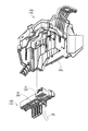
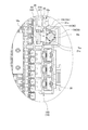
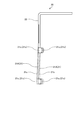
本発明に係る電気接続箱及びワイヤハーネスの実施形態の1つを図1から図10に基づいて説明する。
10 筐体
10d 挿入口
10g 受け部
20 中継バスバ
21 電気接続体
21A 平板電気接続体
21a 一方の平面(合わせ面)
21b 他方の平面
21c ガイド部
22 連結体
30 電子部品
40 バスバ
41 平板電気接続体
41a 一方の平面(合わせ面)
41b 他方の平面
50 固定構造
51,52 貫通孔
53 雌螺子部材
54 雄螺子部材
We 電線
WH ワイヤハーネス
Claims (5)
- 絶縁性の筐体と、
前記筐体の内方で前記筐体に保持される導電性の中継バスバと、
前記筐体の内方の収容完了位置まで挿入され、かつ、前記中継バスバに接続させる導電性のバスバが設けられた電子部品と、
前記筐体に予め保持されている前記中継バスバに対して前記収容完了位置の前記バスバを物理的且つ電気的に接続させる固定構造と、
を備え、
前記中継バスバは、複数の電気接続体と、複数の前記電気接続体を連結させる連結体と、を有し、
複数の前記電気接続体の内の少なくとも1つは、2つの平面を前記筐体の内方で前記筐体に対する前記電子部品の挿入方向に沿わせた平板状の平板電気接続体であり、
前記バスバは、2つの平面を前記挿入方向に沿わせた平板状の平板電気接続体を有し、
前記中継バスバと前記バスバのそれぞれの前記平板電気接続体における2つの平面の内の一方は、前記固定構造によって互いに接し合わされる合わせ面であり、
前記中継バスバと前記バスバのそれぞれの前記平板電気接続体の内の少なくとも一方には、各々の前記合わせ面に対する交差方向への弾性変形が可能な可撓性を持たせ、かつ、前記収容完了位置の前記バスバの前記平板電気接続体が前記中継バスバの前記平板電気接続体に前記固定構造によって接続されていない状態で、前記弾性変形に伴う反力を接続相手となる相手方の前記平板電気接続体に作用させ、
前記筐体には、前記中継バスバの前記平板電気接続体が前記バスバの前記平板電気接続体に作用させた力を前記電子部品から受ける受け部を設けることを特徴とした電気接続箱。 - 前記筐体の内方における前記中継バスバの前記平板電気接続体は、前記筐体に対する前記バスバの前記平板電気接続体の挿入軌跡上に配置することを特徴とした請求項1に記載の電気接続箱。
- 前記筐体は、前記収容完了位置まで前記電子部品を挿入させる挿入口を有し、
前記中継バスバの前記平板電気接続体には、前記筐体の内方での前記挿入口側の端部に、前記挿入口から挿入されてきた前記バスバの前記平板電気接続体の前記合わせ面を自身の前記合わせ面まで案内させるガイド部を設けることを特徴とした請求項1又は2に記載の電気接続箱。 - 前記固定構造は、前記中継バスバと前記バスバのそれぞれの前記平板電気接続体に各々形成された貫通孔と、前記中継バスバの前記平板電気接続体における2つの平面の内の他方に対向配置される雌螺子部材と、前記バスバの前記平板電気接続体における2つの平面の内の他方側からそれぞれの前記貫通孔に挿通させ、前記雌螺子部材に螺合させる雄螺子部材と、を備えることを特徴とした請求項1,2又は3に記載の電気接続箱。
- 絶縁性の筐体と、
前記筐体の内方で前記筐体に保持される導電性の中継バスバと、
前記筐体の内方の収容完了位置まで挿入され、かつ、前記中継バスバに接続させる導電性のバスバが設けられた電子部品と、
前記筐体に予め保持されている前記中継バスバに対して前記収容完了位置の前記バスバを物理的且つ電気的に接続させる固定構造と、
前記中継バスバ及び前記バスバに電気接続され、かつ、前記筐体の内方から外方に引き出される電線と、
を備え、
前記中継バスバは、複数の電気接続体と、複数の前記電気接続体を連結させる連結体と、を有し、
複数の前記電気接続体の内の少なくとも1つは、2つの平面を前記筐体の内方で前記筐体に対する前記電子部品の挿入方向に沿わせた平板状の平板電気接続体であり、
前記バスバは、2つの平面を前記挿入方向に沿わせた平板状の平板電気接続体を有し、
前記中継バスバと前記バスバのそれぞれの前記平板電気接続体における2つの平面の内の一方は、前記固定構造によって互いに接し合わされる合わせ面であり、
前記中継バスバと前記バスバのそれぞれの前記平板電気接続体の内の少なくとも一方には、各々の前記合わせ面に対する交差方向への弾性変形が可能な可撓性を持たせ、かつ、前記収容完了位置の前記バスバの前記平板電気接続体が前記中継バスバの前記平板電気接続体に前記固定構造によって接続されていない状態で、前記弾性変形に伴う反力を接続相手となる相手方の前記平板電気接続体に作用させ、
前記筐体には、前記中継バスバの前記平板電気接続体が前記バスバの前記平板電気接続体に作用させた力を前記電子部品から受ける受け部を設けることを特徴としたワイヤハーネス。
Priority Applications (4)
| Application Number | Priority Date | Filing Date | Title |
|---|---|---|---|
| JP2020000908A JP7013496B2 (ja) | 2020-01-07 | 2020-01-07 | 電気接続箱及びワイヤハーネス |
| EP20216464.6A EP3848251B1 (en) | 2020-01-07 | 2020-12-22 | Electrical connection box and wire harness |
| US17/133,642 US11615935B2 (en) | 2020-01-07 | 2020-12-24 | Electrical connection box and wire harness |
| CN202110011545.2A CN113161947B (zh) | 2020-01-07 | 2021-01-06 | 电气接线箱以及线束 |
Applications Claiming Priority (1)
| Application Number | Priority Date | Filing Date | Title |
|---|---|---|---|
| JP2020000908A JP7013496B2 (ja) | 2020-01-07 | 2020-01-07 | 電気接続箱及びワイヤハーネス |
Publications (2)
| Publication Number | Publication Date |
|---|---|
| JP2021111996A true JP2021111996A (ja) | 2021-08-02 |
| JP7013496B2 JP7013496B2 (ja) | 2022-01-31 |
Family
ID=73856799
Family Applications (1)
| Application Number | Title | Priority Date | Filing Date |
|---|---|---|---|
| JP2020000908A Active JP7013496B2 (ja) | 2020-01-07 | 2020-01-07 | 電気接続箱及びワイヤハーネス |
Country Status (4)
| Country | Link |
|---|---|
| US (1) | US11615935B2 (ja) |
| EP (1) | EP3848251B1 (ja) |
| JP (1) | JP7013496B2 (ja) |
| CN (1) | CN113161947B (ja) |
Families Citing this family (1)
| Publication number | Priority date | Publication date | Assignee | Title |
|---|---|---|---|---|
| JP2021111997A (ja) * | 2020-01-07 | 2021-08-02 | 矢崎総業株式会社 | 電気接続箱及びワイヤハーネス |
Citations (4)
| Publication number | Priority date | Publication date | Assignee | Title |
|---|---|---|---|---|
| JPS57155683U (ja) * | 1981-03-26 | 1982-09-30 | ||
| JPH0584122U (ja) * | 1992-04-17 | 1993-11-12 | 矢崎総業株式会社 | 電気接続箱 |
| JP2012005162A (ja) * | 2010-06-14 | 2012-01-05 | Yazaki Corp | 電気接続箱 |
| JP2019030204A (ja) * | 2017-08-02 | 2019-02-21 | 矢崎総業株式会社 | 電気配線ブロック接合体、電気接続箱及びワイヤハーネス |
Family Cites Families (18)
| Publication number | Priority date | Publication date | Assignee | Title |
|---|---|---|---|---|
| DE3735205A1 (de) * | 1987-10-17 | 1989-04-27 | Reinshagen Kabelwerk Gmbh | Mehrpolige steckbare kupplungshaelfte fuer elektrische leitungen |
| JPH0311912A (ja) * | 1989-06-06 | 1991-01-21 | Naka Tech Lab | フロアパネル開口部の塞ぎ板 |
| JPH05326053A (ja) * | 1992-05-26 | 1993-12-10 | Fujitsu Ltd | 端子ブロック |
| US6322376B1 (en) * | 2000-03-31 | 2001-11-27 | Yazaki North America | Stud bolt holder for a power distribution box |
| JP2004253163A (ja) * | 2003-02-18 | 2004-09-09 | Yazaki Corp | 中継端子及びコネクタ |
| JP5074744B2 (ja) * | 2006-11-15 | 2012-11-14 | 矢崎総業株式会社 | 電気接続箱 |
| JP5109812B2 (ja) * | 2008-05-30 | 2012-12-26 | 住友電装株式会社 | 電気接続箱 |
| JP5228679B2 (ja) * | 2008-07-31 | 2013-07-03 | 住友電装株式会社 | 電流センサーを備えた電気接続箱 |
| JP5157765B2 (ja) * | 2008-09-03 | 2013-03-06 | 住友電装株式会社 | 電気接続箱 |
| JP5141451B2 (ja) * | 2008-09-03 | 2013-02-13 | 住友電装株式会社 | 電気接続箱 |
| US7931479B1 (en) * | 2009-11-17 | 2011-04-26 | Delphi Technologies, Inc. | Bussed electrical center with combination electrical and mechanical connection |
| JP5494236B2 (ja) * | 2010-05-28 | 2014-05-14 | 株式会社オートネットワーク技術研究所 | アース接続装置およびそれを用いたワイヤハーネス |
| CN102290468B (zh) * | 2011-06-17 | 2013-06-12 | 人和光伏科技有限公司 | 太阳能电池接线盒 |
| US8961198B2 (en) * | 2012-06-08 | 2015-02-24 | Lear Corporation | Electrical junction box connections |
| JP6209558B2 (ja) * | 2015-05-29 | 2017-10-04 | 矢崎総業株式会社 | 電気接続箱及びワイヤハーネス |
| FR3041168B1 (fr) * | 2015-09-11 | 2017-09-29 | Schneider Electric Ind Sas | Systeme de raccordement d'une cosse a œil avec un moyen de serrage et des moyens de retenue pour retenir la cosse a œil avant serrage |
| JP2019022312A (ja) * | 2017-07-14 | 2019-02-07 | 日本電産株式会社 | モータ製造方法及びモータ |
| JP6950866B2 (ja) * | 2018-02-08 | 2021-10-13 | 住友電装株式会社 | 暗電流回路の断続構造およびそれを備えた電気接続箱 |
-
2020
- 2020-01-07 JP JP2020000908A patent/JP7013496B2/ja active Active
- 2020-12-22 EP EP20216464.6A patent/EP3848251B1/en active Active
- 2020-12-24 US US17/133,642 patent/US11615935B2/en active Active
-
2021
- 2021-01-06 CN CN202110011545.2A patent/CN113161947B/zh active Active
Patent Citations (4)
| Publication number | Priority date | Publication date | Assignee | Title |
|---|---|---|---|---|
| JPS57155683U (ja) * | 1981-03-26 | 1982-09-30 | ||
| JPH0584122U (ja) * | 1992-04-17 | 1993-11-12 | 矢崎総業株式会社 | 電気接続箱 |
| JP2012005162A (ja) * | 2010-06-14 | 2012-01-05 | Yazaki Corp | 電気接続箱 |
| JP2019030204A (ja) * | 2017-08-02 | 2019-02-21 | 矢崎総業株式会社 | 電気配線ブロック接合体、電気接続箱及びワイヤハーネス |
Also Published As
| Publication number | Publication date |
|---|---|
| US20210210301A1 (en) | 2021-07-08 |
| JP7013496B2 (ja) | 2022-01-31 |
| CN113161947A (zh) | 2021-07-23 |
| EP3848251B1 (en) | 2022-03-09 |
| US11615935B2 (en) | 2023-03-28 |
| EP3848251A1 (en) | 2021-07-14 |
| CN113161947B (zh) | 2022-08-26 |
Similar Documents
| Publication | Publication Date | Title |
|---|---|---|
| JP4100319B2 (ja) | 自動車用のスプライス吸収構造 | |
| WO2016208364A1 (ja) | ジョイントコネクタ | |
| JP4046033B2 (ja) | 自動車用電気接続箱におけるバスバーの半嵌合検知構造 | |
| WO2016208368A1 (ja) | ジョイントコネクタ | |
| JPH0517905U (ja) | 自動車用電気接続装置 | |
| KR20160123214A (ko) | 커넥터 어셈블리 | |
| JPH0680318U (ja) | 電気接続箱 | |
| JP7013496B2 (ja) | 電気接続箱及びワイヤハーネス | |
| JP2005149935A (ja) | 圧接ジョイントコネクタ | |
| US8507809B2 (en) | Component-equipped-holder mounting structure | |
| JP7381523B2 (ja) | 電気接続箱 | |
| CN108174621B (zh) | 连接器单元、装入电气部件的连接器以及带连接器的电气部件 | |
| US7189102B2 (en) | Connector especially for an airbag-ignition system | |
| JP6768304B2 (ja) | コネクタの組立方法 | |
| JP7152251B2 (ja) | 電気配線ブロック接合体、電気接続箱及びワイヤハーネス | |
| JP7118538B2 (ja) | バスバ保持構造、電気接続箱、および、ワイヤハーネス | |
| CN114361841A (zh) | 电端子 | |
| JP5107004B2 (ja) | 合体コネクタ | |
| CN113196576A (zh) | 线束部件 | |
| JP7152250B2 (ja) | 電気配線ブロック接合体、電気接続箱及びワイヤハーネス | |
| JP7080563B2 (ja) | 電気配線ブロック接合体、電気接続箱及びワイヤハーネス | |
| JP4592359B2 (ja) | コネクタ及びコネクタの導通検査方法 | |
| JP2000083313A (ja) | 電気接続箱 | |
| CN107768900B (zh) | 电连接器 | |
| JP2001333517A (ja) | 電気接続箱の分岐接続構造 |
Legal Events
| Date | Code | Title | Description |
|---|---|---|---|
| A621 | Written request for application examination |
Free format text: JAPANESE INTERMEDIATE CODE: A621 Effective date: 20210318 |
|
| A977 | Report on retrieval |
Free format text: JAPANESE INTERMEDIATE CODE: A971007 Effective date: 20220114 |
|
| TRDD | Decision of grant or rejection written | ||
| A01 | Written decision to grant a patent or to grant a registration (utility model) |
Free format text: JAPANESE INTERMEDIATE CODE: A01 Effective date: 20220118 |
|
| A61 | First payment of annual fees (during grant procedure) |
Free format text: JAPANESE INTERMEDIATE CODE: A61 Effective date: 20220119 |
|
| R150 | Certificate of patent or registration of utility model |
Ref document number: 7013496 Country of ref document: JP Free format text: JAPANESE INTERMEDIATE CODE: R150 |
|
| S531 | Written request for registration of change of domicile |
Free format text: JAPANESE INTERMEDIATE CODE: R313531 |
|
| R350 | Written notification of registration of transfer |
Free format text: JAPANESE INTERMEDIATE CODE: R350 |