JP2017147027A - 端子金具付き電線および端子金具付き電線の製造方法 - Google Patents
端子金具付き電線および端子金具付き電線の製造方法 Download PDFInfo
- Publication number
- JP2017147027A JP2017147027A JP2016025565A JP2016025565A JP2017147027A JP 2017147027 A JP2017147027 A JP 2017147027A JP 2016025565 A JP2016025565 A JP 2016025565A JP 2016025565 A JP2016025565 A JP 2016025565A JP 2017147027 A JP2017147027 A JP 2017147027A
- Authority
- JP
- Japan
- Prior art keywords
- braided wire
- metal foil
- terminal
- wire
- terminal fitting
- Prior art date
- Legal status (The legal status is an assumption and is not a legal conclusion. Google has not performed a legal analysis and makes no representation as to the accuracy of the status listed.)
- Pending
Links
Images


Classifications
-
- H—ELECTRICITY
- H01—ELECTRIC ELEMENTS
- H01R—ELECTRICALLY-CONDUCTIVE CONNECTIONS; STRUCTURAL ASSOCIATIONS OF A PLURALITY OF MUTUALLY-INSULATED ELECTRICAL CONNECTING ELEMENTS; COUPLING DEVICES; CURRENT COLLECTORS
- H01R4/00—Electrically-conductive connections between two or more conductive members in direct contact, i.e. touching one another; Means for effecting or maintaining such contact; Electrically-conductive connections having two or more spaced connecting locations for conductors and using contact members penetrating insulation
- H01R4/10—Electrically-conductive connections between two or more conductive members in direct contact, i.e. touching one another; Means for effecting or maintaining such contact; Electrically-conductive connections having two or more spaced connecting locations for conductors and using contact members penetrating insulation effected solely by twisting, wrapping, bending, crimping, or other permanent deformation
- H01R4/18—Electrically-conductive connections between two or more conductive members in direct contact, i.e. touching one another; Means for effecting or maintaining such contact; Electrically-conductive connections having two or more spaced connecting locations for conductors and using contact members penetrating insulation effected solely by twisting, wrapping, bending, crimping, or other permanent deformation by crimping
- H01R4/183—Electrically-conductive connections between two or more conductive members in direct contact, i.e. touching one another; Means for effecting or maintaining such contact; Electrically-conductive connections having two or more spaced connecting locations for conductors and using contact members penetrating insulation effected solely by twisting, wrapping, bending, crimping, or other permanent deformation by crimping for cylindrical elongated bodies, e.g. cables having circular cross-section
-
- H—ELECTRICITY
- H01—ELECTRIC ELEMENTS
- H01R—ELECTRICALLY-CONDUCTIVE CONNECTIONS; STRUCTURAL ASSOCIATIONS OF A PLURALITY OF MUTUALLY-INSULATED ELECTRICAL CONNECTING ELEMENTS; COUPLING DEVICES; CURRENT COLLECTORS
- H01R11/00—Individual connecting elements providing two or more spaced connecting locations for conductive members which are, or may be, thereby interconnected, e.g. end pieces for wires or cables supported by the wire or cable and having means for facilitating electrical connection to some other wire, terminal, or conductive member, blocks of binding posts
- H01R11/11—End pieces or tapping pieces for wires, supported by the wire and for facilitating electrical connection to some other wire, terminal or conductive member
- H01R11/12—End pieces terminating in an eye, hook, or fork
-
- H—ELECTRICITY
- H01—ELECTRIC ELEMENTS
- H01R—ELECTRICALLY-CONDUCTIVE CONNECTIONS; STRUCTURAL ASSOCIATIONS OF A PLURALITY OF MUTUALLY-INSULATED ELECTRICAL CONNECTING ELEMENTS; COUPLING DEVICES; CURRENT COLLECTORS
- H01R4/00—Electrically-conductive connections between two or more conductive members in direct contact, i.e. touching one another; Means for effecting or maintaining such contact; Electrically-conductive connections having two or more spaced connecting locations for conductors and using contact members penetrating insulation
- H01R4/10—Electrically-conductive connections between two or more conductive members in direct contact, i.e. touching one another; Means for effecting or maintaining such contact; Electrically-conductive connections having two or more spaced connecting locations for conductors and using contact members penetrating insulation effected solely by twisting, wrapping, bending, crimping, or other permanent deformation
- H01R4/18—Electrically-conductive connections between two or more conductive members in direct contact, i.e. touching one another; Means for effecting or maintaining such contact; Electrically-conductive connections having two or more spaced connecting locations for conductors and using contact members penetrating insulation effected solely by twisting, wrapping, bending, crimping, or other permanent deformation by crimping
- H01R4/20—Electrically-conductive connections between two or more conductive members in direct contact, i.e. touching one another; Means for effecting or maintaining such contact; Electrically-conductive connections having two or more spaced connecting locations for conductors and using contact members penetrating insulation effected solely by twisting, wrapping, bending, crimping, or other permanent deformation by crimping using a crimping sleeve
-
- H—ELECTRICITY
- H01—ELECTRIC ELEMENTS
- H01R—ELECTRICALLY-CONDUCTIVE CONNECTIONS; STRUCTURAL ASSOCIATIONS OF A PLURALITY OF MUTUALLY-INSULATED ELECTRICAL CONNECTING ELEMENTS; COUPLING DEVICES; CURRENT COLLECTORS
- H01R43/00—Apparatus or processes specially adapted for manufacturing, assembling, maintaining, or repairing of line connectors or current collectors or for joining electric conductors
- H01R43/033—Apparatus or processes specially adapted for manufacturing, assembling, maintaining, or repairing of line connectors or current collectors or for joining electric conductors for wrapping or unwrapping wire connections
-
- H—ELECTRICITY
- H01—ELECTRIC ELEMENTS
- H01R—ELECTRICALLY-CONDUCTIVE CONNECTIONS; STRUCTURAL ASSOCIATIONS OF A PLURALITY OF MUTUALLY-INSULATED ELECTRICAL CONNECTING ELEMENTS; COUPLING DEVICES; CURRENT COLLECTORS
- H01R43/00—Apparatus or processes specially adapted for manufacturing, assembling, maintaining, or repairing of line connectors or current collectors or for joining electric conductors
- H01R43/04—Apparatus or processes specially adapted for manufacturing, assembling, maintaining, or repairing of line connectors or current collectors or for joining electric conductors for forming connections by deformation, e.g. crimping tool
- H01R43/048—Crimping apparatus or processes
-
- H—ELECTRICITY
- H01—ELECTRIC ELEMENTS
- H01R—ELECTRICALLY-CONDUCTIVE CONNECTIONS; STRUCTURAL ASSOCIATIONS OF A PLURALITY OF MUTUALLY-INSULATED ELECTRICAL CONNECTING ELEMENTS; COUPLING DEVICES; CURRENT COLLECTORS
- H01R43/00—Apparatus or processes specially adapted for manufacturing, assembling, maintaining, or repairing of line connectors or current collectors or for joining electric conductors
- H01R43/28—Apparatus or processes specially adapted for manufacturing, assembling, maintaining, or repairing of line connectors or current collectors or for joining electric conductors for wire processing before connecting to contact members, not provided for in groups H01R43/02 - H01R43/26
-
- H—ELECTRICITY
- H01—ELECTRIC ELEMENTS
- H01R—ELECTRICALLY-CONDUCTIVE CONNECTIONS; STRUCTURAL ASSOCIATIONS OF A PLURALITY OF MUTUALLY-INSULATED ELECTRICAL CONNECTING ELEMENTS; COUPLING DEVICES; CURRENT COLLECTORS
- H01R9/00—Structural associations of a plurality of mutually-insulated electrical connecting elements, e.g. terminal strips or terminal blocks; Terminals or binding posts mounted upon a base or in a case; Bases therefor
- H01R9/03—Connectors arranged to contact a plurality of the conductors of a multiconductor cable, e.g. tapping connections
- H01R9/05—Connectors arranged to contact a plurality of the conductors of a multiconductor cable, e.g. tapping connections for coaxial cables
- H01R9/0518—Connection to outer conductor by crimping or by crimping ferrule
Abstract
Description
本発明の端子金具付き電線の製造方法は、編組線を切断する切断工程と、前記編組線に金属箔を巻き付ける巻き付け工程と、前記金属箔が巻き付けられた編組線の端部に前記端子金具を接続する端子接続工程と、を経る方法である。
本発明の端子金具付き電線は、前記編組線の端部が折り返されて重ね合わされているものとしてもよい。
以下、本発明を具体化した実施例1について、図1〜図3を参照しつつ詳細に説明する。
本実施例における端子金具付き電線10は、編組線11と、編組線11の長手方向の両端部に接続された一対の端子金具12とを備えている。
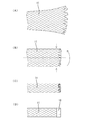
まず、編組線11を切断する切断工程を行う。切断工程は、編組線11を幅方向に折り返していない状態(幅方向に平たく延びた状態)で行う。図示しないカッター装置により、編組線11の所定の位置を切断し、編組線11を所定の長さ寸法にする。切断された編組線11の端部は、図3(A)に示すように、素線がばらけて広がりやすくなっている。
以上により、端子金具付き電線10の製造が完了する。
本実施例の端子金具付き電線10は、編組線11の端部に、金属箔18が巻き付けられるとともに、端子金具12が接続されているものである。この構成によれば、金属箔18によって、編組線11の端部の素線がばらけて広がることを防ぐことができるから、溶接装置を用いることなく端子金具付き電線10を製造することができる。
次に、本発明を具体化した実施例2に係る端子金具付き電線10の製造方法を説明する。
本実施例の端子金具付き電線10の製造方法は、編組線11の切断部位に金属箔18を巻き付ける巻き付け工程の後に、金属箔18が巻き付けられた状態の切断部位を切断する切断工程を行う点で、実施例1とは相違する。なお、実施例1と同様の構成には同一符号を付して重複する説明を省略する。
まず、編組線11の切断部位に、金属箔18を巻き付ける巻き付け工程を行う。実施例1と同様、所定の長さ寸法にカットした金属箔18を、編組線11の切断部位に全周にわたって巻き付けて接着する。巻き付け工程は、編組線11を幅方向に折り返していない状態(幅方向に平たく延びた状態)で行う。
本発明は上記記述及び図面によって説明した実施例に限定されるものではなく、例えば次のような実施例も本発明の技術的範囲に含まれる。
(1)上記実施例では、編組線11の両端部に接続される端子金具12の具体例を示したが、これに限らず、端子金具は、各種の端子金具を用いることができる。
(2)上記実施例では、編組線11の端部が二つ折りされているが、これに限らず、例えば編組線の端部を三つ折りにしたり丸めたりしてもよい。
(3)上記実施例では、編組線11の端部が折り返されて重ね合わされているが、これに限らず、編組線の端部を折り返さないで平坦なものとしてもよい。
(4)上記実施例では、編組線11の端部が、幅方向における中心で二つ折りされているが、これに限らず、編組線の端部の幅方向における両端縁部を中心側に折り返してもよい。
(5)上記実施例では、編組線11の端部が幅方向に折り返されているが、これに限らず、編組線の端部を軸方向に折り返してもよい。
(6)上記実施例1では、折り返し工程の後に巻き付け工程を行っているが、これに限らず、巻き付け工程の後に折り返し工程を行ってもよい。
(7)上記実施例2では、巻き付け工程の後に折り返し工程を行っているが、これに限らず、折り返し工程の後に巻き付け工程を行ってもよい。
11…編組線
12…端子金具
18…金属箔
Claims (6)
- 編組線の端部に、金属箔が巻き付けられるとともに、巻き付けられた前記金属箔の外側に、端子金具が接続されている端子金具付き電線。
- 前記編組線の端部が折り返されて重ね合わされている請求項1に記載の端子金具付き電線。
- 編組線を切断する切断工程と、
前記編組線に金属箔を巻き付ける巻き付け工程と、
前記金属箔が巻き付けられた編組線の端部に前記端子金具を接続する端子接続工程と、
を経る端子金具付き電線の製造方法。 - 前記切断工程の後に、前記編組線の端部に前記金属箔を巻き付ける巻き付け工程を行う請求項3に記載の端子金具付き電線の製造方法。
- 前記編組線の切断部位に前記金属箔を巻き付ける巻き付け工程の後に、
前記金属箔が巻き付けられた状態の前記切断部位を切断する切断工程を行う請求項3に記載の端子金具付き電線の製造方法。 - 前記切断工程の後に、
前記編組線の端部を折り返して重ね合わせる折り返し工程を行う請求項3ないし請求項5のいずれか一項に記載の端子金具付き電線の製造方法。
Priority Applications (3)
| Application Number | Priority Date | Filing Date | Title |
|---|---|---|---|
| JP2016025565A JP2017147027A (ja) | 2016-02-15 | 2016-02-15 | 端子金具付き電線および端子金具付き電線の製造方法 |
| US15/427,739 US9847586B2 (en) | 2016-02-15 | 2017-02-08 | Metal terminal fitting crimped to a folded end portion of a braided wire |
| CN201710073634.3A CN107086379B (zh) | 2016-02-15 | 2017-02-10 | 带端子零件的电线以及带端子零件的电线的制造方法 |
Applications Claiming Priority (1)
| Application Number | Priority Date | Filing Date | Title |
|---|---|---|---|
| JP2016025565A JP2017147027A (ja) | 2016-02-15 | 2016-02-15 | 端子金具付き電線および端子金具付き電線の製造方法 |
Publications (1)
| Publication Number | Publication Date |
|---|---|
| JP2017147027A true JP2017147027A (ja) | 2017-08-24 |
Family
ID=59561813
Family Applications (1)
| Application Number | Title | Priority Date | Filing Date |
|---|---|---|---|
| JP2016025565A Pending JP2017147027A (ja) | 2016-02-15 | 2016-02-15 | 端子金具付き電線および端子金具付き電線の製造方法 |
Country Status (3)
| Country | Link |
|---|---|
| US (1) | US9847586B2 (ja) |
| JP (1) | JP2017147027A (ja) |
| CN (1) | CN107086379B (ja) |
Families Citing this family (2)
| Publication number | Priority date | Publication date | Assignee | Title |
|---|---|---|---|---|
| CN111370381B (zh) * | 2020-03-27 | 2022-04-01 | 广东芯聚能半导体有限公司 | 连接组件、功率半导体及适用于功率半导体的连接方法 |
| JP7435338B2 (ja) * | 2020-07-27 | 2024-02-21 | 住友電装株式会社 | シールド電線の端末構造およびスリーブ |
Family Cites Families (13)
| Publication number | Priority date | Publication date | Assignee | Title |
|---|---|---|---|---|
| JP3421555B2 (ja) * | 1997-11-07 | 2003-06-30 | 矢崎総業株式会社 | 同軸ケーブル用コネクタの接続構造及びその接続方法 |
| JP4074097B2 (ja) * | 2001-04-27 | 2008-04-09 | モレックス インコーポレーテッド | プラグ |
| JP5072098B2 (ja) * | 2008-01-24 | 2012-11-14 | 矢崎総業株式会社 | 圧着端子 |
| JP5058082B2 (ja) * | 2008-06-18 | 2012-10-24 | 株式会社オートネットワーク技術研究所 | 端子金具及び端子付き電線 |
| JP5147648B2 (ja) * | 2008-11-07 | 2013-02-20 | 矢崎総業株式会社 | 圧着端子及び圧着端子における電線固定構造 |
| JP5233822B2 (ja) * | 2009-04-24 | 2013-07-10 | 住友電装株式会社 | 端子金具 |
| JP5566716B2 (ja) * | 2010-02-05 | 2014-08-06 | 矢崎総業株式会社 | ワイヤハーネス |
| JP5359975B2 (ja) * | 2010-04-07 | 2013-12-04 | 住友電装株式会社 | 端子金具 |
| JP2012009229A (ja) * | 2010-06-23 | 2012-01-12 | Jst Mfg Co Ltd | 同軸ケーブル用コンタクト及び端末処理方法 |
| JP5687955B2 (ja) * | 2011-05-20 | 2015-03-25 | 矢崎総業株式会社 | アルミ電線と金属端子の圧着接続部の構造及びその製法 |
| CN202584921U (zh) * | 2012-04-17 | 2012-12-05 | 浙江万马天屹通信线缆有限公司 | 三屏蔽同轴电缆的短卷边形铝箔 |
| JP6032558B2 (ja) | 2013-09-17 | 2016-11-30 | 住友電装株式会社 | 端子金具付き導体 |
| US9362633B2 (en) * | 2013-11-07 | 2016-06-07 | Pds Electronics, Inc. | Hybridized coaxial cable connector |
-
2016
- 2016-02-15 JP JP2016025565A patent/JP2017147027A/ja active Pending
-
2017
- 2017-02-08 US US15/427,739 patent/US9847586B2/en not_active Expired - Fee Related
- 2017-02-10 CN CN201710073634.3A patent/CN107086379B/zh not_active Expired - Fee Related
Also Published As
| Publication number | Publication date |
|---|---|
| CN107086379B (zh) | 2019-11-12 |
| US20170237183A1 (en) | 2017-08-17 |
| CN107086379A (zh) | 2017-08-22 |
| US9847586B2 (en) | 2017-12-19 |
Similar Documents
| Publication | Publication Date | Title |
|---|---|---|
| JP5913851B2 (ja) | 電線の接続方法 | |
| US9444154B2 (en) | Terminal fitting-equipped conductor | |
| JP5235369B2 (ja) | ワイヤーハーネスおよびその製造方法ならびに絶縁電線の接続方法 | |
| JP6163149B2 (ja) | 端子付き電線の製造方法 | |
| US9755325B2 (en) | Terminal, wire harness, terminal and coated conductor wire connection method, and wire harness structure | |
| JP2014011133A (ja) | 端子金具付き編組線および端子金具付き編組線の製造方法 | |
| JP5369637B2 (ja) | 端子金具付き電線及びその製造方法 | |
| JP2015041509A (ja) | 導電路及び電線 | |
| JP2017147027A (ja) | 端子金具付き電線および端子金具付き電線の製造方法 | |
| JP2017220392A (ja) | 端子付き電線 | |
| JP6774627B2 (ja) | 電線の接合構造及びワイヤハーネス | |
| JP6316230B2 (ja) | 接続端子付き電線及びその電線の製造方法 | |
| JP6479535B2 (ja) | 端子、端子付き電線、ワイヤハーネス構造体 | |
| WO2018092597A1 (ja) | 圧着端子および端子付き電線 | |
| JP2016167340A (ja) | ジョイント部材及びワイヤーハーネス | |
| JP2016201330A (ja) | ワイヤーハーネス及びシート状電線部材 | |
| JP6316229B2 (ja) | 接続端子付き電線及びその電線の製造方法 | |
| JP6022525B2 (ja) | 電線接続用スリーブ | |
| JP2017168400A (ja) | 端子付電線及びその製造方法 | |
| JP2014022143A (ja) | 端子付き導電体及び端子付き導電体の製造方法 | |
| JP5720955B2 (ja) | 端子の製造方法および連鎖端子 | |
| US10892566B2 (en) | Conductor connection, connection piece and method for fabricating a conductor connection | |
| JP2017168398A (ja) | 端子付電線及びその製造方法 | |
| JP2014164828A (ja) | 端子付電線製造方法、及び端子付電線 | |
| JP2020004653A (ja) | 端子付電線及びその製造方法 |
Legal Events
| Date | Code | Title | Description |
|---|---|---|---|
| A621 | Written request for application examination |
Free format text: JAPANESE INTERMEDIATE CODE: A621 Effective date: 20180530 |
|
| A977 | Report on retrieval |
Free format text: JAPANESE INTERMEDIATE CODE: A971007 Effective date: 20190319 |
|
| A131 | Notification of reasons for refusal |
Free format text: JAPANESE INTERMEDIATE CODE: A131 Effective date: 20190409 |
|
| A521 | Request for written amendment filed |
Free format text: JAPANESE INTERMEDIATE CODE: A523 Effective date: 20190523 |
|
| A02 | Decision of refusal |
Free format text: JAPANESE INTERMEDIATE CODE: A02 Effective date: 20191008 |