JP2010143316A - 単線固定循環式索道の停留場構造 - Google Patents
単線固定循環式索道の停留場構造 Download PDFInfo
- Publication number
- JP2010143316A JP2010143316A JP2008320975A JP2008320975A JP2010143316A JP 2010143316 A JP2010143316 A JP 2010143316A JP 2008320975 A JP2008320975 A JP 2008320975A JP 2008320975 A JP2008320975 A JP 2008320975A JP 2010143316 A JP2010143316 A JP 2010143316A
- Authority
- JP
- Japan
- Prior art keywords
- pulley
- cableway
- rope
- boarding position
- carrier
- Prior art date
- Legal status (The legal status is an assumption and is not a legal conclusion. Google has not performed a legal analysis and makes no representation as to the accuracy of the status listed.)
- Granted
Links
Images
Landscapes
- Lift-Guide Devices, And Elevator Ropes And Cables (AREA)
Abstract
単線固定循環式索道の停留場で滑車を周回した搬器の遠心力による振れを乗車位置で緩和して乗客が移動する搬器へ乗車し易くする。
【解決手段】
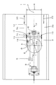
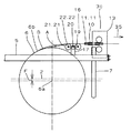
単線固定循環式索道の停留場3で索条12を巻き掛けて、搬器13を到着側3aから出発側3bへ転向する原動滑車6の滑車径Dを線路ゲージRより小さい寸度として、接線が到着側3aの索道線路1と一致するように、索道中心2よりオフセット量Fだけ到着側3aに変位して配置する。そして、出発側3aでは原動滑車6の索条12の接触起点6bと、乗車位置3c上に配置した2輪索受装置10との間に2輪拡索装置16を設けて、平面視で緩和曲線Bに近似する近似屈曲経路Aを構成し、原動滑車6を周回する際に生じた遠心力による振れを乗車位置3cを通過するまでに緩和する。
【選択図】 図4
Description
2 索道中心
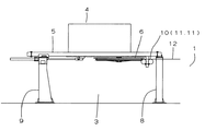
3 停留場
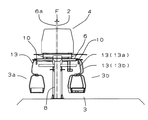
3a 到着側
3b 出発側
3c 乗車位置
4 原動装置
5 原動フレーム
6 原動滑車
6a 滑車中心
6b 接触起点
7 アーム
8 前脚
9 後脚
10 2輪索受装置
11,11 受索輪
12 索条
13,13,… 搬器
13a 搬器滑車出口位置
13b 搬器乗車位置
14 握索機
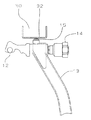
15 振止プラグ
16 2輪拡索装置
17 ブラケット
19 2輪ビーム
20 2輪ビームピン
21,21 索輪
22,22 ピン
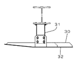
30 振止ガイド
31 ブラケット
32 レール
33,34,35 矢印
A 近似屈曲経路
B 緩和曲線
D 滑車径
F オフセット量
R 線路ゲージ
Claims (2)
- 単線固定循環式索道の停留場で、線路ゲージより小径で搬器を懸垂した索条を巻き掛けて、該索条を到着側より出発側に転向するための滑車と、該滑車の索条との接触起点から乗車位置に設けた索受装置との間に装着し、索条を前記滑車の出発側出口から線路ゲージにまで水平方向に屈曲させて搬器の屈曲移動経路を形成するための拡索装置とよりなり、前記屈曲移動経路は滑車の索条との接触起点と乗車位置との間にできる緩和曲線に近似させて構成したことを特徴とする単線固定循環式索道の停留場構造。
- 前記滑車の索条を巻き掛けた到着側の接線は到着側の索道線路と一致するように、滑車の滑車中心を線路ゲージの中心に対して到着側へオフセットして配置した請求項1に記載の単線固定循環式索道の停留場構造。
Priority Applications (1)
| Application Number | Priority Date | Filing Date | Title |
|---|---|---|---|
| JP2008320975A JP5191370B2 (ja) | 2008-12-17 | 2008-12-17 | 単線固定循環式索道の停留場構造 |
Applications Claiming Priority (1)
| Application Number | Priority Date | Filing Date | Title |
|---|---|---|---|
| JP2008320975A JP5191370B2 (ja) | 2008-12-17 | 2008-12-17 | 単線固定循環式索道の停留場構造 |
Publications (2)
| Publication Number | Publication Date |
|---|---|
| JP2010143316A true JP2010143316A (ja) | 2010-07-01 |
| JP5191370B2 JP5191370B2 (ja) | 2013-05-08 |
Family
ID=42564203
Family Applications (1)
| Application Number | Title | Priority Date | Filing Date |
|---|---|---|---|
| JP2008320975A Active JP5191370B2 (ja) | 2008-12-17 | 2008-12-17 | 単線固定循環式索道の停留場構造 |
Country Status (1)
| Country | Link |
|---|---|
| JP (1) | JP5191370B2 (ja) |
Cited By (1)
| Publication number | Priority date | Publication date | Assignee | Title |
|---|---|---|---|---|
| CN105329240A (zh) * | 2015-11-20 | 2016-02-17 | 华南农业大学 | 一种链式货运索道减振装置及方法 |
Citations (5)
| Publication number | Priority date | Publication date | Assignee | Title |
|---|---|---|---|---|
| JPS5987364U (ja) * | 1982-12-06 | 1984-06-13 | 株式会社明輝電機製作所 | 索道搬器の振れ抑制装置 |
| JPS6027074Y2 (ja) * | 1979-06-29 | 1985-08-15 | 日本ケ−ブル株式会社 | リフト搬器用制振リングの緩衝構造 |
| JPS62174973U (ja) * | 1986-04-26 | 1987-11-06 | ||
| JPH10217954A (ja) * | 1997-02-10 | 1998-08-18 | Mitsubishi Heavy Ind Ltd | 搬器の制振装置 |
| JP2005271681A (ja) * | 2004-03-24 | 2005-10-06 | Nippon Cable Co Ltd | 緩衝機構を備えた索道搬器の補助振れ止めガイド |
-
2008
- 2008-12-17 JP JP2008320975A patent/JP5191370B2/ja active Active
Patent Citations (5)
| Publication number | Priority date | Publication date | Assignee | Title |
|---|---|---|---|---|
| JPS6027074Y2 (ja) * | 1979-06-29 | 1985-08-15 | 日本ケ−ブル株式会社 | リフト搬器用制振リングの緩衝構造 |
| JPS5987364U (ja) * | 1982-12-06 | 1984-06-13 | 株式会社明輝電機製作所 | 索道搬器の振れ抑制装置 |
| JPS62174973U (ja) * | 1986-04-26 | 1987-11-06 | ||
| JPH10217954A (ja) * | 1997-02-10 | 1998-08-18 | Mitsubishi Heavy Ind Ltd | 搬器の制振装置 |
| JP2005271681A (ja) * | 2004-03-24 | 2005-10-06 | Nippon Cable Co Ltd | 緩衝機構を備えた索道搬器の補助振れ止めガイド |
Cited By (1)
| Publication number | Priority date | Publication date | Assignee | Title |
|---|---|---|---|---|
| CN105329240A (zh) * | 2015-11-20 | 2016-02-17 | 华南农业大学 | 一种链式货运索道减振装置及方法 |
Also Published As
| Publication number | Publication date |
|---|---|
| JP5191370B2 (ja) | 2013-05-08 |
Similar Documents
| Publication | Publication Date | Title |
|---|---|---|
| US9033115B2 (en) | Zip line braking | |
| US8166885B2 (en) | Suspended cable amusement ride | |
| US8746149B2 (en) | Turn wheel and method for supporting a curved portion of a load-transporting cable | |
| RU2650058C1 (ru) | Рельсовые пути и привод аттракциона, установленного на башне | |
| US20090255436A1 (en) | Ricky braking system for zipline riders | |
| CN108579098B (zh) | 一种侧向摆动过山车 | |
| KR101635940B1 (ko) | 활강 레포츠 장치 | |
| KR102075864B1 (ko) | 영구자석을 이용한 와전류 브레이크가 설치된 짚라인 트롤리 | |
| CN105939764A (zh) | 改变轨道车辆行进方向的装置,具有这种装置的轨道游乐设施以及操作这种装置的方法 | |
| JP5191370B2 (ja) | 単線固定循環式索道の停留場構造 | |
| KR20190015284A (ko) | 오버헤드 운반 시스템 | |
| KR101300582B1 (ko) | 트롤리 락커 이동 장치 | |
| CN107792085A (zh) | 一种吊厢式滑车轨道变轨机构及索道网系统 | |
| JPH09323806A (ja) | 搬送装置 | |
| BR112016017695B1 (pt) | Sistema de teleférico | |
| JP6474074B2 (ja) | 索道の支索サドル | |
| KR102358956B1 (ko) | 활강 놀이기구 출도착 자동연동 브레이크 시스템 | |
| EP4208380B1 (fr) | Installation de transport | |
| KR102252838B1 (ko) | 안전도착 유도를 위한 보조 감속장치가 구비된 공중활강이동장치 | |
| JP4379975B2 (ja) | 制振装置の給電装置 | |
| CN111284505B (zh) | 一种架空乘人车防脱绳保护装置 | |
| JP5288856B2 (ja) | 複線交走式索道における搬器振れ抑制装置 | |
| FR2926803A1 (fr) | Economie d'energie par suppression du contrepoids d'un ascenseur pour machineries stationnaires avec un controle de positionnement et de vitesse | |
| JP5236248B2 (ja) | 固定循環式索道の乗り越し検出器 | |
| JP2011173451A (ja) | 索道設備のプラットホームにおける可動ステップ |
Legal Events
| Date | Code | Title | Description |
|---|---|---|---|
| A621 | Written request for application examination |
Free format text: JAPANESE INTERMEDIATE CODE: A621 Effective date: 20111213 |
|
| RD03 | Notification of appointment of power of attorney |
Free format text: JAPANESE INTERMEDIATE CODE: A7423 Effective date: 20111213 |
|
| A977 | Report on retrieval |
Free format text: JAPANESE INTERMEDIATE CODE: A971007 Effective date: 20130116 |
|
| TRDD | Decision of grant or rejection written | ||
| A01 | Written decision to grant a patent or to grant a registration (utility model) |
Free format text: JAPANESE INTERMEDIATE CODE: A01 Effective date: 20130129 |
|
| A61 | First payment of annual fees (during grant procedure) |
Free format text: JAPANESE INTERMEDIATE CODE: A61 Effective date: 20130129 |
|
| R150 | Certificate of patent or registration of utility model |
Ref document number: 5191370 Country of ref document: JP Free format text: JAPANESE INTERMEDIATE CODE: R150 Free format text: JAPANESE INTERMEDIATE CODE: R150 |
|
| FPAY | Renewal fee payment (event date is renewal date of database) |
Free format text: PAYMENT UNTIL: 20160208 Year of fee payment: 3 |