JP2010143316A - Station structure of single track fixed circulating type cableway - Google Patents
Station structure of single track fixed circulating type cableway Download PDFInfo
- Publication number
- JP2010143316A JP2010143316A JP2008320975A JP2008320975A JP2010143316A JP 2010143316 A JP2010143316 A JP 2010143316A JP 2008320975 A JP2008320975 A JP 2008320975A JP 2008320975 A JP2008320975 A JP 2008320975A JP 2010143316 A JP2010143316 A JP 2010143316A
- Authority
- JP
- Japan
- Prior art keywords
- pulley
- cableway
- rope
- boarding position
- carrier
- Prior art date
- Legal status (The legal status is an assumption and is not a legal conclusion. Google has not performed a legal analysis and makes no representation as to the accuracy of the status listed.)
- Granted
Links
Images
Landscapes
- Lift-Guide Devices, And Elevator Ropes And Cables (AREA)
Abstract
Description
本発明は主に単線固定循環式索道で、滑車を周回する際に搬器に生じる遠心力の変化を緩和させ、搬器の外振れを緩和するようにした停留場の構造に関する。 The present invention mainly relates to a structure of a stationary field which is a single track fixed circulation type cableway, and is designed to reduce a change in centrifugal force generated in a carrier when circling a pulley and to reduce an outer shake of the carrier.
山麓と山頂の停留場に配備した滑車間に、搬器を握索機で懸垂した索条を巻き掛けて、循環移動させることで搬器を運行する単線固定循環式索道で、搬器が滑車を周回する際に遠心力の作用で滑車の外側に向けて外振れする。この搬器の外振れを抑制するために、索条を握索して搬器を索条に固着懸垂する握索機の頂部に樹脂製の振止めプラグを上方に突出して具える。また、索条を巻き掛けた滑車には振止めプラグに当接する振止めリングを取り付ける。こうして、搬器が滑車を周回する際に、遠心力の作用で外側に振れようとすると、握索機の振止めプラグが滑車に取り付けた振止めリングに当接して、搬器の外振れが抑制されるようにしている。(特許文献1の図1を参照) A single-line fixed-circulation cableway that operates a carrier by wrapping a rope suspended by a grinder between the pulleys deployed at the foot of the mountain and the summit. The carrier circulates around the pulley. At that time, the outer side of the pulley swings out due to the centrifugal force. In order to suppress the external shake of the transporter, a resin swing plug is protruded upward at the top of the gripper that grips the rope and fixes the transporter to the rope. A pulley ring that abuts against a vibration plug is attached to the pulley around which the rope is wound. Thus, when the transporter orbits around the pulley, if it tries to swing outward by the action of centrifugal force, the swing plug of the grinder will abut against the swing ring attached to the pulley and the external swing of the transporter will be suppressed. I try to do it. (See FIG. 1 of Patent Document 1)
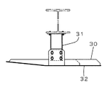
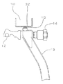
また、図5、図6で示すように滑車の索条が巻き掛け入り口側付近の原動フレームにブラケット31を取り付け側面視で略船型をしたレール32を懸架して構成した振止めガイド30を装備して、図6に示す搬器13の握索機14の頂部に取り付けた振止めプラグ15が前記振止めガイド30のレール32の底面に当接して、滑車の入り口側で搬器13の振れを抑止する装置が用いられている。
単線固定循環式索道では停留場に配備されて滑車を索条の移動速度(2.0m/s)速度で周回して搬器の進行方向が折り返されるが、かかる搬器には遠心力が作用する。この搬器の外振れは搬器が滑車を周回している間は、上記したように滑車に取り付けた振止めリングで搬器の握索機に具えた振止めプラグを押さえられて抑制される。その後搬器が滑車の周回を終わると、握索機の振止めプラグが滑車の振止めリングから外れて、搬器の遠心力が作用した座席の慣性で、線路の外側に振れながら乗車位置に向けて進行する。従って、乗車位置で待機している乗客は外振れしながら接近してくる搬器に乗車することになり、乗客に対して多少とも不安感や乗り辛さを感じさせることになる。本発明の課題は搬器が滑車を周回して乗車位置に移動するまでの経路で上記した搬器の外振れを緩和することで、乗客(スキーヤー等)が乗車位置で移動する搬器へ多少とも安全に乗車することができる単線固定循環式索道の停留場構造を提供することにある。 In the single track fixed circulation type cableway, it is installed at a stop and turns the pulley at the moving speed (2.0 m / s) of the rope to turn the traveling direction of the carrier, but centrifugal force acts on the carrier. While the carrier is orbiting the pulley, the outer shake of the carrier is suppressed by holding the vibration plug attached to the gripping device of the carrier with the vibration ring attached to the pulley as described above. After that, when the transporter finishes the rounding of the pulley, the gripping plug of the grappler comes off from the swinging ring of the pulley, and it moves toward the boarding position while swinging outside the track due to the inertia of the seat where the centrifugal force of the transporter acts. proceed. Therefore, the passenger waiting at the boarding position gets on the carrying device approaching while swinging, and makes the passenger feel a little uneasy or difficult to ride. An object of the present invention is to relax the above-mentioned external shake of the transporter on the route until the transporter goes around the pulley and moves to the boarding position, so that the passenger (skier or the like) moves to the transporter moving at the boarding position more or less safely. The object is to provide a single-line fixed circulation cableway stop structure that can be boarded.
この課題を解決するために本発明は、単線固定循環式索道の停留場で、線路ゲージより小径で搬器を懸垂した索条を巻き掛けて、該索条を到着側より出発側に転向するための滑車と、該滑車の出発側出口から乗車位置に設けた索受装置との間に装着し、索条を前記滑車の出発側出口から線路ゲージにまで水平方向に屈曲させて搬器の移動経路を形成するための拡索装置とよりなり、前記移動経路は滑車の出発側出口と乗車位置との間にできる緩和曲線に近似させて形成する。 In order to solve this problem, the present invention is for stopping a single-line fixed-circulation cableway, wrapping a cable having a smaller diameter than the line gauge and hanging the carrier, and turning the cable from the arrival side to the departure side. And a cable receiving device provided at the boarding position from the departure side exit of the pulley, and the rope is bent in the horizontal direction from the departure side exit of the pulley to the track gauge. The moving path is formed by approximating a relaxation curve formed between the starting exit of the pulley and the boarding position.
さらに、前記滑車の索条を巻き掛けた到着側の接線は到着側の索道線路と一致するように、滑車の滑車中心を線路ゲージの中心に対して到着側へオフセットして配置する。 Further, the pulley center of the pulley is arranged offset to the arrival side with respect to the center of the track gauge so that the arrival side tangent around which the strip of the pulley is wound coincides with the cableway on the arrival side.
従来の如く、搬器の振れを機械的に抑制するための振止めガイドを必要とせず、滑車を周回する際に遠心力で生じる搬器の振れを、滑車の出口から乗車位置までの移動経路で緩和することで、乗客が乗車位置で移動する搬器に乗車する際に、乗客に安全性や安心感を与えることができる効果がある。 Unlike conventional systems, there is no need for an anti-vibration guide to mechanically suppress the swing of the transporter, and the swing of the transporter caused by centrifugal force when circling the pulley is mitigated by the movement path from the exit of the pulley to the boarding position. Thus, when the passenger gets on the transporter that moves at the boarding position, there is an effect that safety and security can be given to the passenger.
停留場に設けて搬器を握索機で懸垂した索条を巻き掛けた滑車の直径を索道の線路ゲージより小さくして、滑車中心を線路中心に対して到着側へオフセットして到着側の索道線路と滑車の接線とを合致するように配備する。これに対して、出発側では平面視で滑車の索条の巻き掛け接触起点と乗車位置上にある索受装置の間に拡索装置を配置して、滑車の索条の巻き掛け接触起点と索受装置との間で作る緩和曲線に近似して搬器の屈曲移動経路を形成して、搬器が滑車を周回して滑車から離れ、乗車位置に到達するまでの間滑車を周回する際の遠心力による搬器の振れを緩和して、乗客が乗車位置で移動する搬器に乗車し易くする。 The cableway on the arrival side is offset by setting the diameter of the pulley around the cable gauge of the cableway to be smaller than the track gauge of the cableway, and offsetting the pulley center to the arrival side with respect to the track center. The track and the tangent line of the pulley are arranged to match. On the other hand, on the departure side, in a plan view, an expansion device is arranged between the pulley contact point of the pulley line and the receiving device on the boarding position, and the pulley contact point of the pulley line Approximate the relaxation curve created with the receiving device to form a bending movement path of the carrier, and the centrifuge when turning around the pulley until the carrier circulates around the pulley and leaves the pulley until it reaches the boarding position. The swing of the transporter due to the force is alleviated, and the passenger can easily get on the transporter moving at the boarding position.
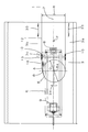
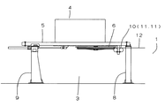
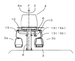
以下、本発明の実施の形態を図を用いて説明する。図1は単線固定循環式索道で本発明の構造を適用した停留場3の平面図、図2は図1の側面図、図3は図1の正面図を示す。図示した停留場3は原動装置4を配置した原動停留場である。即ち、地上には索道線路1の方向の前後に位置して前脚8と後脚9を立設して、この間、平面視で形鋼を長方形状に枠組しで構成の原動フレーム5を渡架固設する。かかる原動フレーム5には索道線路1方向に油圧緊張シリンダーで移動可能に原動滑車6を装着する。
Hereinafter, embodiments of the present invention will be described with reference to the drawings. FIG. 1 is a plan view of a
上記で、原動滑車6の滑車径Dは線路ゲージRより小さい寸度のものを用いる。そして、かかる原動滑車6の接線を到着側3aの線路ゲージRと一致させるように、滑車中心6aを索道中心2に対してオフセット量Fだけ到着側3a方向に変位させて原動フレーム5に回転可能に枢軸する。
In the above, the pulley diameter D of the
従って、図1で示すように、線路ゲージRより原動滑車6の滑車径Dが小さいため、停留場3の出発側3bでは線路ゲージRと原動滑車6の索道線路1に向かう接線との間には水平方向にオフセット量Fの2倍に相当する寸度のずれが生じる。
Therefore, as shown in FIG. 1, since the pulley diameter D of the
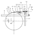
図4は上記を説明した原動滑車6の出発側3bでの索条12の移動経路、即ち、搬器13の移動経路を示した平面図である。図示するように、索道では周知であるが、原動フレーム5には乗車位置3c上に位置するようにして2輪の受索輪11,11を鉛直方向に回転可能に枢着して構成し、索条12を鉛直の向きで下から支承する2輪索受装置10をアーム7の先端部に配備する。
FIG. 4 is a plan view showing the moving path of the
つづいて、原動滑車6に索条12を巻き掛けた接触起点6bから前記線路ゲージRの出発側の線路上に位置する2輪索受装置10に向けて索条12を水平方向に屈曲誘導するための2輪拡索装置16を原動フレーム5へ装着する。該2輪拡索装置16は2輪ビーム19の両端部に各々ピン22,22で索輪21,21を水平方向に回転可能に枢着し、さらに該2輪ビーム19の中心を2輪ビームピン20でブラケット17へ水平方向に旋回可能に軸支した平衡構造にする。
Subsequently, the
上記した構造の2輪拡索装置16は原動滑車6の索条12の接触起点6bと乗車位置3cの上部に位置する2輪索受装置10との間に平面視で形成する緩和曲線と近似する搬器13の近似屈曲経路Aを構成するように原動フレーム5へ装備する。
The two-
こうして、図1、図3、図4で示すように、索道線路1から矢印33方向に進行して停留場3に到着した搬器13は、索条12と共に到着側3aでアーム7に装着された2輪索受装置10で原動滑車6に誘導され、出発側3bに向けて原動滑車6の外縁部を矢印34方向に周回する。
Thus, as shown in FIGS. 1, 3, and 4, the
続いて、搬器13は原動滑車6の索条12の接触起点6bまで周回した搬器滑車出口位置13aから、前記2輪拡索装置16で構成された緩和曲線Bに近似する近似屈曲経路Aを通過して出発側3bに配備した2輪索受装置10の搬器乗車位置13bに至り、索道線路1の線路ゲージRと一致させるように索条12の移動と共に運行する。
Subsequently, the
こうして、原動滑車6を周回して遠心力で該原動滑車6の外側に向けて振れた搬器13は、続く近似屈曲経路Aを通過することで前記搬器13の振れが緩和されて2輪索受装置10のある乗車位置3cに至り、該乗車位置3cで待機していた乗客が搬器13へ乗車した後に矢印35方向の索道線路1に向けて停留場3を出発する。こうして、乗客が乗車位置3cで移動する搬器13に乗車する際、原動滑車6を周回する際に生じた振れ緩和されるので、乗客はより安全かつ容易に乗車することが可能になる。
Thus, the
上記で、原動滑車6の索条12の接触起点6bと乗車位置3c上にある2輪索受装置10との間の平面視で緩和曲線Bに近似する近似屈曲経路Aを2輪拡索装置16で構成したが、索輪21の数や配置について前記説明に限定されること無く、本発明の主旨に基づき様々な態様は勿論可能である。
In the above, the two-wheel expansion device has an approximate bending path A that approximates the relaxation curve B in a plan view between the
1 索道線路
2 索道中心
3 停留場
3a 到着側
3b 出発側
3c 乗車位置
4 原動装置
5 原動フレーム
6 原動滑車
6a 滑車中心
6b 接触起点
7 アーム
8 前脚
9 後脚
10 2輪索受装置
11,11 受索輪
12 索条
13,13,… 搬器
13a 搬器滑車出口位置
13b 搬器乗車位置
14 握索機
15 振止プラグ
16 2輪拡索装置
17 ブラケット
19 2輪ビーム
20 2輪ビームピン
21,21 索輪
22,22 ピン
30 振止ガイド
31 ブラケット
32 レール
33,34,35 矢印
A 近似屈曲経路
B 緩和曲線
D 滑車径
F オフセット量
R 線路ゲージ
DESCRIPTION OF
13a Carriage
Claims (2)
Priority Applications (1)
| Application Number | Priority Date | Filing Date | Title |
|---|---|---|---|
| JP2008320975A JP5191370B2 (en) | 2008-12-17 | 2008-12-17 | Single track fixed circulation cableway stop structure |
Applications Claiming Priority (1)
| Application Number | Priority Date | Filing Date | Title |
|---|---|---|---|
| JP2008320975A JP5191370B2 (en) | 2008-12-17 | 2008-12-17 | Single track fixed circulation cableway stop structure |
Publications (2)
| Publication Number | Publication Date |
|---|---|
| JP2010143316A true JP2010143316A (en) | 2010-07-01 |
| JP5191370B2 JP5191370B2 (en) | 2013-05-08 |
Family
ID=42564203
Family Applications (1)
| Application Number | Title | Priority Date | Filing Date |
|---|---|---|---|
| JP2008320975A Active JP5191370B2 (en) | 2008-12-17 | 2008-12-17 | Single track fixed circulation cableway stop structure |
Country Status (1)
| Country | Link |
|---|---|
| JP (1) | JP5191370B2 (en) |
Cited By (1)
| Publication number | Priority date | Publication date | Assignee | Title |
|---|---|---|---|---|
| CN105329240A (en) * | 2015-11-20 | 2016-02-17 | 华南农业大学 | Chain-type freight ropeway vibration attenuation device and method |
Citations (5)
| Publication number | Priority date | Publication date | Assignee | Title |
|---|---|---|---|---|
| JPS5987364U (en) * | 1982-12-06 | 1984-06-13 | 株式会社明輝電機製作所 | Sway control device for cableway carriers |
| JPS6027074Y2 (en) * | 1979-06-29 | 1985-08-15 | 日本ケ−ブル株式会社 | Buffer structure of damping ring for lift carrier |
| JPS62174973U (en) * | 1986-04-26 | 1987-11-06 | ||
| JPH10217954A (en) * | 1997-02-10 | 1998-08-18 | Mitsubishi Heavy Ind Ltd | Damping device for carrier |
| JP2005271681A (en) * | 2004-03-24 | 2005-10-06 | Nippon Cable Co Ltd | Auxiliary swing preventing guide of cableway carrier provided with buffer mechanism |
-
2008
- 2008-12-17 JP JP2008320975A patent/JP5191370B2/en active Active
Patent Citations (5)
| Publication number | Priority date | Publication date | Assignee | Title |
|---|---|---|---|---|
| JPS6027074Y2 (en) * | 1979-06-29 | 1985-08-15 | 日本ケ−ブル株式会社 | Buffer structure of damping ring for lift carrier |
| JPS5987364U (en) * | 1982-12-06 | 1984-06-13 | 株式会社明輝電機製作所 | Sway control device for cableway carriers |
| JPS62174973U (en) * | 1986-04-26 | 1987-11-06 | ||
| JPH10217954A (en) * | 1997-02-10 | 1998-08-18 | Mitsubishi Heavy Ind Ltd | Damping device for carrier |
| JP2005271681A (en) * | 2004-03-24 | 2005-10-06 | Nippon Cable Co Ltd | Auxiliary swing preventing guide of cableway carrier provided with buffer mechanism |
Cited By (1)
| Publication number | Priority date | Publication date | Assignee | Title |
|---|---|---|---|---|
| CN105329240A (en) * | 2015-11-20 | 2016-02-17 | 华南农业大学 | Chain-type freight ropeway vibration attenuation device and method |
Also Published As
| Publication number | Publication date |
|---|---|
| JP5191370B2 (en) | 2013-05-08 |
Similar Documents
| Publication | Publication Date | Title |
|---|---|---|
| US8166885B2 (en) | Suspended cable amusement ride | |
| RU2650058C1 (en) | Tracks and roller coaster mounted on a tower area | |
| US20090255436A1 (en) | Ricky braking system for zipline riders | |
| US20130112103A1 (en) | Turn wheel for supporting a curved portion of a load-transporting cable | |
| CN108579098B (en) | Side direction swing roller coaster | |
| KR101635940B1 (en) | The apparatus for a leisure downhill sports | |
| KR102075864B1 (en) | Zip line trolley with eddy current brake using permanent magnet | |
| CN105939764A (en) | Device for changing the direction of travel of a rail-bound vehicle, rail-bound ride having such a device, and method for operating such a device | |
| JP5191370B2 (en) | Single track fixed circulation cableway stop structure | |
| CN109311485A (en) | Overhead Transport Equipment | |
| CN109501963B (en) | A kind of ship guide wire work control method | |
| KR101300582B1 (en) | apparatus for moving trolley locker | |
| JPH09323806A (en) | Transportation device | |
| BR112016017695B1 (en) | CABLE CAR SYSTEM | |
| ES2890824T3 (en) | air transportation facility | |
| JP6474074B2 (en) | Cableway Saddle | |
| KR102358956B1 (en) | Downhill ride brake system with the function of automatic connection between departure and arrival | |
| KR102252838B1 (en) | Zip coaster equipped with auxiliary reduction device for inducing safe arrival | |
| KR20130003224U (en) | Safe-arrival guidance system for an air descent experience ride | |
| JP4379975B2 (en) | Power supply device for vibration control device | |
| EP4208380B1 (en) | Transport facility | |
| CN111284505B (en) | A kind of anti-rope-off protection device for overhead passenger vehicle | |
| JP5288856B2 (en) | Carriage shake control device for double track crossing cableway | |
| JP5236248B2 (en) | Fixed circulation type cableway detector | |
| JP2008222105A (en) | Rubber liner for guide pulley for cableway |
Legal Events
| Date | Code | Title | Description |
|---|---|---|---|
| A621 | Written request for application examination |
Free format text: JAPANESE INTERMEDIATE CODE: A621 Effective date: 20111213 |
|
| RD03 | Notification of appointment of power of attorney |
Free format text: JAPANESE INTERMEDIATE CODE: A7423 Effective date: 20111213 |
|
| A977 | Report on retrieval |
Free format text: JAPANESE INTERMEDIATE CODE: A971007 Effective date: 20130116 |
|
| TRDD | Decision of grant or rejection written | ||
| A01 | Written decision to grant a patent or to grant a registration (utility model) |
Free format text: JAPANESE INTERMEDIATE CODE: A01 Effective date: 20130129 |
|
| A61 | First payment of annual fees (during grant procedure) |
Free format text: JAPANESE INTERMEDIATE CODE: A61 Effective date: 20130129 |
|
| R150 | Certificate of patent or registration of utility model |
Ref document number: 5191370 Country of ref document: JP Free format text: JAPANESE INTERMEDIATE CODE: R150 Free format text: JAPANESE INTERMEDIATE CODE: R150 |
|
| FPAY | Renewal fee payment (event date is renewal date of database) |
Free format text: PAYMENT UNTIL: 20160208 Year of fee payment: 3 |