JP2010093326A - イメージセンサモジュール - Google Patents
イメージセンサモジュール Download PDFInfo
- Publication number
- JP2010093326A JP2010093326A JP2008258270A JP2008258270A JP2010093326A JP 2010093326 A JP2010093326 A JP 2010093326A JP 2008258270 A JP2008258270 A JP 2008258270A JP 2008258270 A JP2008258270 A JP 2008258270A JP 2010093326 A JP2010093326 A JP 2010093326A
- Authority
- JP
- Japan
- Prior art keywords
- substrate
- case
- image sensor
- sensor module
- optical system
- Prior art date
- Legal status (The legal status is an assumption and is not a legal conclusion. Google has not performed a legal analysis and makes no representation as to the accuracy of the status listed.)
- Granted
Links
- 230000003287 optical effect Effects 0.000 claims abstract description 23
- 239000000758 substrate Substances 0.000 claims description 84
- 230000000903 blocking effect Effects 0.000 abstract 1
- 239000011521 glass Substances 0.000 description 6
- 230000001681 protective effect Effects 0.000 description 6
- 239000011347 resin Substances 0.000 description 4
- 229920005989 resin Polymers 0.000 description 4
- 238000006073 displacement reaction Methods 0.000 description 3
- 230000001678 irradiating effect Effects 0.000 description 2
- 229920003229 poly(methyl methacrylate) Polymers 0.000 description 2
- 239000000463 material Substances 0.000 description 1
- 230000000149 penetrating effect Effects 0.000 description 1
- 239000004926 polymethyl methacrylate Substances 0.000 description 1
Images


Landscapes
- Facsimile Heads (AREA)
Abstract
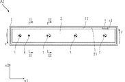
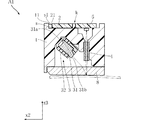
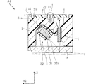
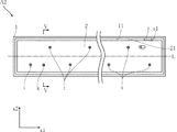
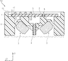
【解決手段】光源と、上記光源から発せられて画像読み取り領域から反射してくる光を集束させる光学系と、上記光学系によって集束された光を受けることにより所定の信号を出力するセンサチップを表面に搭載している、長矩形状の基板2と、上記光学系を収容しているとともに、基板2を装着しているケース1と、を備えるイメージセンサモジュールA1において、基板2は、ケース1に対する基板2の並進移動を阻止するとともに、ケース1に対する基板2の回転移動を許容する固定点kと、ネジを用いた締結部tと、においてケース1に装着されており、ケース1には、上記ネジの締結方向と逆方向yに向かって固定点を中心として基板2の側面21が回転する場合の進行方向の前方に、基板2の回転を停止させるストッパsが形成されている。
【選択図】 図1
Description
1 ケース
11 壁面
2 基板
21 側面
3 線状光源ユニット
31 導光体
31a 反射面
31b 出射面
32 リフレクタ
4 光学系
5 センサチップ
8 保護ガラス
s ストッパ
s1 面
k 固定点
t 締結部
t1 雄ネジ
t2 雌ネジ
L 基準線
Claims (4)
- 光源と、
上記光源から発せられて画像読み取り領域から反射してくる光を集束させる光学系と、
上記光学系によって集束された光を受けることにより所定の信号を出力するセンサチップを表面に搭載している、長矩形状の基板と、
上記光学系を収容しているとともに、上記基板を装着しているケースと、
を備えるイメージセンサモジュールにおいて、
上記基板は、上記ケースに対する上記基板の並進移動を阻止するとともに、上記ケースに対する上記基板の回転移動を許容する固定点と、ネジを用いた締結部と、において上記ケースに装着されており、
上記ケースには、上記ネジの締結方向と逆方向に向かって上記固定点を中心として上記基板の長手方向の側面が回転する場合の進行方向の前方に、上記基板の回転を停止させるストッパが形成されたことを特徴とする、イメージセンサモジュール。 - 上記ケースには、上記基板の長手方向に延びるとともに、隙間を隔てて上記側面と対向する壁面を備え、
上記ストッパは、上記壁面から上記側面に向かって突出しており、かつ、上記壁面と平行な、上記側面と当接している面を有する、請求項1に記載のイメージセンサモジュール。 - 上記固定点は、上記基板の中央と上記基板の上記長手方向の一端との間に位置しており、
上記基板が上記ストッパと接する部分は、上記基板の中央と上記基板の上記長手方向の他端との間に位置している、請求項1または2に記載のイメージセンサモジュール。 - 上記センサチップは、上記基板の長手方向に沿って延びる基準線に沿って配置されており、
複数の上記締結部は、上記基板の短手方向において上記基準線の両側に位置している、請求項1ないし3のいずれかに記載のイメージセンサモジュール。
Priority Applications (1)
| Application Number | Priority Date | Filing Date | Title |
|---|---|---|---|
| JP2008258270A JP5112242B2 (ja) | 2008-10-03 | 2008-10-03 | イメージセンサモジュール |
Applications Claiming Priority (1)
| Application Number | Priority Date | Filing Date | Title |
|---|---|---|---|
| JP2008258270A JP5112242B2 (ja) | 2008-10-03 | 2008-10-03 | イメージセンサモジュール |
Publications (2)
| Publication Number | Publication Date |
|---|---|
| JP2010093326A true JP2010093326A (ja) | 2010-04-22 |
| JP5112242B2 JP5112242B2 (ja) | 2013-01-09 |
Family
ID=42255684
Family Applications (1)
| Application Number | Title | Priority Date | Filing Date |
|---|---|---|---|
| JP2008258270A Expired - Fee Related JP5112242B2 (ja) | 2008-10-03 | 2008-10-03 | イメージセンサモジュール |
Country Status (1)
| Country | Link |
|---|---|
| JP (1) | JP5112242B2 (ja) |
Citations (3)
| Publication number | Priority date | Publication date | Assignee | Title |
|---|---|---|---|---|
| JPH02268562A (ja) * | 1989-04-11 | 1990-11-02 | Konica Corp | イメージセンサー |
| JPH07142691A (ja) * | 1993-11-16 | 1995-06-02 | Rohm Co Ltd | イメージセンサ |
| JPH08128590A (ja) * | 1994-10-31 | 1996-05-21 | Junichiro Kuze | 逆ネジ防止用カップラー |
-
2008
- 2008-10-03 JP JP2008258270A patent/JP5112242B2/ja not_active Expired - Fee Related
Patent Citations (3)
| Publication number | Priority date | Publication date | Assignee | Title |
|---|---|---|---|---|
| JPH02268562A (ja) * | 1989-04-11 | 1990-11-02 | Konica Corp | イメージセンサー |
| JPH07142691A (ja) * | 1993-11-16 | 1995-06-02 | Rohm Co Ltd | イメージセンサ |
| JPH08128590A (ja) * | 1994-10-31 | 1996-05-21 | Junichiro Kuze | 逆ネジ防止用カップラー |
Also Published As
| Publication number | Publication date |
|---|---|
| JP5112242B2 (ja) | 2013-01-09 |
Similar Documents
| Publication | Publication Date | Title |
|---|---|---|
| JP2004266313A (ja) | 画像読み取り装置 | |
| KR20150084904A (ko) | 화상 판독 장치 | |
| JP2007292756A (ja) | 高性能反射性光学エンコーダ | |
| JP3824357B2 (ja) | 光半導体装置 | |
| JP4313762B2 (ja) | 導光ユニットおよびこれを備えた画像読み取り装置 | |
| JP2009150690A (ja) | 反射型光学センサ | |
| JP4877048B2 (ja) | 導光体および線状光源装置 | |
| US7940433B2 (en) | Image sensor | |
| JP2006049231A (ja) | 車両用標識灯 | |
| JP4946603B2 (ja) | 導光体および線状光源装置 | |
| JP5012790B2 (ja) | 照明装置及びそれを用いた画像読取装置 | |
| JP5112242B2 (ja) | イメージセンサモジュール | |
| JP4999596B2 (ja) | 反射型フォトセンサ | |
| JP5161610B2 (ja) | イメージセンサモジュール | |
| JP2017076867A (ja) | イメージセンサモジュール | |
| JP4205117B2 (ja) | 光学式反射型情報読み取りセンサおよび電子機器 | |
| JP2009038321A (ja) | 反射型フォトセンサ | |
| JP5000535B2 (ja) | イメージセンサモジュール | |
| US20080084625A1 (en) | Scanning module | |
| TWI507011B (zh) | 接觸式影像感測裝置 | |
| JP2009165110A (ja) | 画像読取装置 | |
| JP5249592B2 (ja) | イメージセンサモジュールの製造方法およびイメージセンサモジュール | |
| JP5087520B2 (ja) | イメージセンサモジュール | |
| JP6247510B2 (ja) | イメージセンサモジュール | |
| JP2016015031A (ja) | 光学ラインセンサ装置 |
Legal Events
| Date | Code | Title | Description |
|---|---|---|---|
| A621 | Written request for application examination |
Free format text: JAPANESE INTERMEDIATE CODE: A621 Effective date: 20110921 |
|
| A977 | Report on retrieval |
Free format text: JAPANESE INTERMEDIATE CODE: A971007 Effective date: 20120907 |
|
| TRDD | Decision of grant or rejection written | ||
| A01 | Written decision to grant a patent or to grant a registration (utility model) |
Free format text: JAPANESE INTERMEDIATE CODE: A01 Effective date: 20120918 |
|
| A01 | Written decision to grant a patent or to grant a registration (utility model) |
Free format text: JAPANESE INTERMEDIATE CODE: A01 |
|
| A61 | First payment of annual fees (during grant procedure) |
Free format text: JAPANESE INTERMEDIATE CODE: A61 Effective date: 20121010 |
|
| FPAY | Renewal fee payment (event date is renewal date of database) |
Free format text: PAYMENT UNTIL: 20151019 Year of fee payment: 3 |
|
| R150 | Certificate of patent or registration of utility model |
Ref document number: 5112242 Country of ref document: JP Free format text: JAPANESE INTERMEDIATE CODE: R150 Free format text: JAPANESE INTERMEDIATE CODE: R150 |
|
| R250 | Receipt of annual fees |
Free format text: JAPANESE INTERMEDIATE CODE: R250 |
|
| R250 | Receipt of annual fees |
Free format text: JAPANESE INTERMEDIATE CODE: R250 |
|
| LAPS | Cancellation because of no payment of annual fees |