JP2010028919A - 電気接続箱の端子装着構造 - Google Patents
電気接続箱の端子装着構造 Download PDFInfo
- Publication number
- JP2010028919A JP2010028919A JP2008184692A JP2008184692A JP2010028919A JP 2010028919 A JP2010028919 A JP 2010028919A JP 2008184692 A JP2008184692 A JP 2008184692A JP 2008184692 A JP2008184692 A JP 2008184692A JP 2010028919 A JP2010028919 A JP 2010028919A
- Authority
- JP
- Japan
- Prior art keywords
- terminal
- plate portion
- pair
- bolt
- connection box
- Prior art date
- Legal status (The legal status is an assumption and is not a legal conclusion. Google has not performed a legal analysis and makes no representation as to the accuracy of the status listed.)
- Granted
Links
Images


Classifications
-
- B—PERFORMING OPERATIONS; TRANSPORTING
- B60—VEHICLES IN GENERAL
- B60R—VEHICLES, VEHICLE FITTINGS, OR VEHICLE PARTS, NOT OTHERWISE PROVIDED FOR
- B60R16/00—Electric or fluid circuits specially adapted for vehicles and not otherwise provided for; Arrangement of elements of electric or fluid circuits specially adapted for vehicles and not otherwise provided for
- B60R16/02—Electric or fluid circuits specially adapted for vehicles and not otherwise provided for; Arrangement of elements of electric or fluid circuits specially adapted for vehicles and not otherwise provided for electric constitutive elements
- B60R16/04—Arrangement of batteries
-
- B—PERFORMING OPERATIONS; TRANSPORTING
- B60—VEHICLES IN GENERAL
- B60R—VEHICLES, VEHICLE FITTINGS, OR VEHICLE PARTS, NOT OTHERWISE PROVIDED FOR
- B60R16/00—Electric or fluid circuits specially adapted for vehicles and not otherwise provided for; Arrangement of elements of electric or fluid circuits specially adapted for vehicles and not otherwise provided for
- B60R16/02—Electric or fluid circuits specially adapted for vehicles and not otherwise provided for; Arrangement of elements of electric or fluid circuits specially adapted for vehicles and not otherwise provided for electric constitutive elements
- B60R16/023—Electric or fluid circuits specially adapted for vehicles and not otherwise provided for; Arrangement of elements of electric or fluid circuits specially adapted for vehicles and not otherwise provided for electric constitutive elements for transmission of signals between vehicle parts or subsystems
- B60R16/0238—Electrical distribution centers
-
- H—ELECTRICITY
- H01—ELECTRIC ELEMENTS
- H01R—ELECTRICALLY-CONDUCTIVE CONNECTIONS; STRUCTURAL ASSOCIATIONS OF A PLURALITY OF MUTUALLY-INSULATED ELECTRICAL CONNECTING ELEMENTS; COUPLING DEVICES; CURRENT COLLECTORS
- H01R11/00—Individual connecting elements providing two or more spaced connecting locations for conductive members which are, or may be, thereby interconnected, e.g. end pieces for wires or cables supported by the wire or cable and having means for facilitating electrical connection to some other wire, terminal, or conductive member, blocks of binding posts
- H01R11/11—End pieces or tapping pieces for wires, supported by the wire and for facilitating electrical connection to some other wire, terminal or conductive member
- H01R11/12—End pieces terminating in an eye, hook, or fork
-
- H—ELECTRICITY
- H01—ELECTRIC ELEMENTS
- H01R—ELECTRICALLY-CONDUCTIVE CONNECTIONS; STRUCTURAL ASSOCIATIONS OF A PLURALITY OF MUTUALLY-INSULATED ELECTRICAL CONNECTING ELEMENTS; COUPLING DEVICES; CURRENT COLLECTORS
- H01R4/00—Electrically-conductive connections between two or more conductive members in direct contact, i.e. touching one another; Means for effecting or maintaining such contact; Electrically-conductive connections having two or more spaced connecting locations for conductors and using contact members penetrating insulation
- H01R4/28—Clamped connections, spring connections
- H01R4/30—Clamped connections, spring connections utilising a screw or nut clamping member
- H01R4/305—Clamped connections, spring connections utilising a screw or nut clamping member having means for facilitating engagement of conductive member or for holding it in position
-
- H—ELECTRICITY
- H01—ELECTRIC ELEMENTS
- H01R—ELECTRICALLY-CONDUCTIVE CONNECTIONS; STRUCTURAL ASSOCIATIONS OF A PLURALITY OF MUTUALLY-INSULATED ELECTRICAL CONNECTING ELEMENTS; COUPLING DEVICES; CURRENT COLLECTORS
- H01R4/00—Electrically-conductive connections between two or more conductive members in direct contact, i.e. touching one another; Means for effecting or maintaining such contact; Electrically-conductive connections having two or more spaced connecting locations for conductors and using contact members penetrating insulation
- H01R4/28—Clamped connections, spring connections
- H01R4/30—Clamped connections, spring connections utilising a screw or nut clamping member
- H01R4/34—Conductive members located under head of screw
Landscapes
- Engineering & Computer Science (AREA)
- Mechanical Engineering (AREA)
- Connection Or Junction Boxes (AREA)
- Connections Arranged To Contact A Plurality Of Conductors (AREA)
- Connections By Means Of Piercing Elements, Nuts, Or Screws (AREA)
- Cooling Or The Like Of Electrical Apparatus (AREA)
Abstract
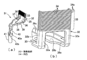
【解決手段】電気接続箱5のバスバー21に端子1をボルト20で締付接続し、端子がボルト頭部を挿通する垂直な開口8と、ボルト軸部を挿入する水平な切欠孔11とを連通して有する電気接続箱の端子装着構造で、ボルトの両側で接続箱本体6に一対のガイド壁18を対向して設け、ガイド壁は、上から下に傾斜した入口側の傾斜面18aと、傾斜面に続く真直な水平面18bとを有し、端子1は、傾斜面と水平面とに順次摺接する一対の外向きの突片3を有する。端子31の垂直な開口35を有する垂直板部32の上部に放熱板部33を一体に延長形成し、放熱板部の表裏面に複数本の線状の凹凸34を形成し、放熱板部の表裏両面を外部に露出させた。
【選択図】図1
Description
3,30 突片
5,42 電気接続箱
6 接続箱本体
8,35 開口
11,38 切欠孔
18,49 ガイド壁
18a 傾斜面
18b 水平面
20,45 ボルト
21,44 バスバー
32 垂直板部
33 放熱板部
34 凹凸
Claims (2)
- 電気接続箱のバスバーに端子がボルトで締付接続され、該端子がボルト頭部を挿通する垂直な開口と、ボルト軸部を挿入する水平な切欠孔とを連通して有した電気接続箱の端子装着構造であって、
前記ボルトの両側で接続箱本体に一対のガイド壁が対向して設けられ、該ガイド壁が、上から下に傾斜した入口側の傾斜面と、該傾斜面に続く真直な水平面とを有し、前記端子が、該傾斜面と該水平面とに順次摺接する一対の外向きの突片を有したことを特徴とする電気接続箱の端子装着構造。 - 前記端子の前記垂直な開口を有する垂直板部の上部に放熱板部が一体に延長形成され、該放熱板部の表裏面に複数本の線状の凹凸が形成され、該放熱板部の表裏両面が外部に露出されたことを特徴とする請求項1記載の電気接続箱の端子装着構造。
Priority Applications (6)
| Application Number | Priority Date | Filing Date | Title |
|---|---|---|---|
| JP2008184692A JP5131981B2 (ja) | 2008-07-16 | 2008-07-16 | 電気接続箱の端子装着構造 |
| CA2715523A CA2715523C (en) | 2008-07-16 | 2009-06-01 | Terminal mounting structure in electrical junction box |
| EP09797760.7A EP2302750B1 (en) | 2008-07-16 | 2009-06-01 | Terminal installation structure for electrical junction box |
| US12/866,816 US7914300B2 (en) | 2008-07-16 | 2009-06-01 | Terminal mounting structure in electrical junction box |
| CN200980107251.7A CN101960685B (zh) | 2008-07-16 | 2009-06-01 | 电接线盒的端子安装结构 |
| PCT/JP2009/059970 WO2010007832A1 (ja) | 2008-07-16 | 2009-06-01 | 電気接続箱の端子装着構造 |
Applications Claiming Priority (1)
| Application Number | Priority Date | Filing Date | Title |
|---|---|---|---|
| JP2008184692A JP5131981B2 (ja) | 2008-07-16 | 2008-07-16 | 電気接続箱の端子装着構造 |
Publications (2)
| Publication Number | Publication Date |
|---|---|
| JP2010028919A true JP2010028919A (ja) | 2010-02-04 |
| JP5131981B2 JP5131981B2 (ja) | 2013-01-30 |
Family
ID=41550241
Family Applications (1)
| Application Number | Title | Priority Date | Filing Date |
|---|---|---|---|
| JP2008184692A Active JP5131981B2 (ja) | 2008-07-16 | 2008-07-16 | 電気接続箱の端子装着構造 |
Country Status (6)
| Country | Link |
|---|---|
| US (1) | US7914300B2 (ja) |
| EP (1) | EP2302750B1 (ja) |
| JP (1) | JP5131981B2 (ja) |
| CN (1) | CN101960685B (ja) |
| CA (1) | CA2715523C (ja) |
| WO (1) | WO2010007832A1 (ja) |
Cited By (7)
| Publication number | Priority date | Publication date | Assignee | Title |
|---|---|---|---|---|
| JP2012239280A (ja) * | 2011-05-11 | 2012-12-06 | Toyota Motor Corp | 端子台の組み付け構造 |
| JP2013143802A (ja) * | 2012-01-10 | 2013-07-22 | Yazaki Corp | 電気接続箱 |
| JP2013248974A (ja) * | 2012-05-31 | 2013-12-12 | Hayama Denki Seisakusho:Kk | 給電接続具 |
| DE102014216934A1 (de) | 2013-09-03 | 2015-03-05 | Yazaki Corporation | Verbindungsstruktur für einen Schraubklemmenanschluß |
| JP2016031434A (ja) * | 2014-07-28 | 2016-03-07 | 株式会社リコー | サーモスタットの保持機構及び定着装置及び画像形成装置 |
| JP2018041580A (ja) * | 2016-09-06 | 2018-03-15 | 住友電装株式会社 | 端子モジュール |
| KR20230100398A (ko) * | 2021-12-28 | 2023-07-05 | 주식회사 유라코퍼레이션 | 정션블록 |
Families Citing this family (27)
| Publication number | Priority date | Publication date | Assignee | Title |
|---|---|---|---|---|
| JP5299698B2 (ja) * | 2009-10-28 | 2013-09-25 | 住友電装株式会社 | 電気接続箱 |
| JP5360582B2 (ja) * | 2009-10-28 | 2013-12-04 | 住友電装株式会社 | 電気接続箱 |
| US8547684B2 (en) * | 2009-12-17 | 2013-10-01 | Schneider Electric USA, Inc. | Panelboard having a parallel feeder bars distribution |
| CN102623812B (zh) * | 2011-01-27 | 2014-11-26 | 深圳市沃尔核材股份有限公司 | 电容型绝缘风电母线端部接线装置 |
| US8480423B2 (en) | 2011-08-16 | 2013-07-09 | Tyco Electronics Corporation | Contact region of an electrically conductive member |
| JP5370436B2 (ja) * | 2011-08-24 | 2013-12-18 | トヨタ自動車株式会社 | バッテリ搭載構造 |
| CN103959585B (zh) * | 2011-09-29 | 2017-09-01 | 矢崎总业株式会社 | 连接器 |
| JP5910942B2 (ja) * | 2012-05-29 | 2016-04-27 | 矢崎総業株式会社 | 端子保護カバーおよび電気接続箱 |
| DE102012218806A1 (de) * | 2012-10-16 | 2014-04-17 | Tyco Electronics Amp Gmbh | Gehäuse für einen Stromverteiler |
| SE536980C2 (sv) * | 2013-03-04 | 2014-11-25 | Scania Cv Ab | Ledningssko |
| JP2014189188A (ja) * | 2013-03-27 | 2014-10-06 | Showa Corp | ステアリング装置 |
| JP6106518B2 (ja) * | 2013-05-09 | 2017-04-05 | 矢崎総業株式会社 | 丸端子固定構造 |
| JP6287891B2 (ja) * | 2015-02-24 | 2018-03-07 | 株式会社オートネットワーク技術研究所 | 電気接続箱及び接続端子部品 |
| DE102015209279A1 (de) * | 2015-05-21 | 2016-11-24 | Robert Bosch Gmbh | Elektrische Kontaktanordnung |
| US9882357B2 (en) * | 2015-06-26 | 2018-01-30 | Hamilton Sundstrand Corporation | Power distribution panel connector having thermal management feature |
| KR102250291B1 (ko) * | 2015-08-13 | 2021-05-10 | 현대자동차주식회사 | 차량용 엔진룸의 전력공급장치 |
| US9887477B1 (en) * | 2016-09-22 | 2018-02-06 | Ford Global Technologies, Llc | Fused-wire cable connectors for a busbar |
| US10608301B2 (en) | 2017-08-29 | 2020-03-31 | Nio Usa, Inc. | Power electronics with integrated busbar cooling |
| US10217693B1 (en) * | 2017-08-29 | 2019-02-26 | Nio Usa, Inc. | Methods and systems for high voltage component cooling in electric vehicle for fast charge |
| CN108501840B (zh) * | 2018-03-14 | 2023-07-07 | 厦门宏发电力电器有限公司 | 一种配电盒连接结构 |
| JP6996483B2 (ja) * | 2018-12-06 | 2022-01-17 | 株式会社オートネットワーク技術研究所 | 回路構成体 |
| US10498053B1 (en) | 2019-02-19 | 2019-12-03 | Stephen Sawzin | Electrical wiring junction box |
| US10971714B2 (en) * | 2019-03-15 | 2021-04-06 | GM Global Technology Operations LLC | Battery pack and a pre-assembled electrical connection unit for the battery pack |
| USD925468S1 (en) * | 2019-09-04 | 2021-07-20 | S2B, Inc. | Relay box |
| CN211508140U (zh) * | 2020-04-01 | 2020-09-15 | 吉林省中赢高科技有限公司 | 一种异形接头 |
| KR102714029B1 (ko) * | 2020-10-29 | 2024-10-04 | 주식회사 엘지에너지솔루션 | 배터리 모듈, 이를 포함하는 배터리 팩 및 자동차 |
| EP4287409A1 (en) | 2022-06-03 | 2023-12-06 | Aptiv Technologies Limited | Electrical connector for connecting high voltage power cable comprising electrical conductor to electrical terminal |
Citations (2)
| Publication number | Priority date | Publication date | Assignee | Title |
|---|---|---|---|---|
| JPH10172633A (ja) * | 1996-12-03 | 1998-06-26 | Yazaki Corp | 端子保護カバー |
| JP2002184299A (ja) * | 2000-12-11 | 2002-06-28 | Toyota Auto Body Co Ltd | 斜め締め防止端子の締め忘れ防止構造 |
Family Cites Families (10)
| Publication number | Priority date | Publication date | Assignee | Title |
|---|---|---|---|---|
| JPH01213855A (ja) | 1988-02-23 | 1989-08-28 | Matsushita Electric Ind Co Ltd | テープガイド装置 |
| GB9408878D0 (en) * | 1994-05-05 | 1994-06-22 | Amp Gmbh | Electrical connector assembly with screw clamp terminals |
| JPH1131450A (ja) * | 1997-05-12 | 1999-02-02 | Yazaki Corp | ヒュージブルリンクの取付方法並びに該方法に用いる端子及びヒュージブルリンクハウジング |
| JPH11213855A (ja) | 1998-01-27 | 1999-08-06 | Yazaki Corp | ヒュージブルリンクの取付方法 |
| FR2790331B1 (fr) * | 1999-02-25 | 2001-06-01 | Peugeot Citroen Automobiles Sa | Dispositif de raccordement electrique d'un conducteur sur une surface de contact |
| JP4341464B2 (ja) * | 2004-05-11 | 2009-10-07 | 富士電機機器制御株式会社 | 電気機器の端子装置 |
| JP2006004733A (ja) | 2004-06-17 | 2006-01-05 | Yazaki Corp | ボルトを用いた端子接続構造とそれを備えた電気接続箱 |
| JP4344308B2 (ja) * | 2004-11-18 | 2009-10-14 | 矢崎総業株式会社 | 電気接続箱 |
| JP4878473B2 (ja) * | 2005-11-22 | 2012-02-15 | 矢崎総業株式会社 | 端子金具と該端子金具を備えた電気接続箱 |
| JP5123027B2 (ja) * | 2008-04-03 | 2013-01-16 | 矢崎総業株式会社 | ねじ締め用端子の係止構造 |
-
2008
- 2008-07-16 JP JP2008184692A patent/JP5131981B2/ja active Active
-
2009
- 2009-06-01 EP EP09797760.7A patent/EP2302750B1/en not_active Not-in-force
- 2009-06-01 CA CA2715523A patent/CA2715523C/en not_active Expired - Fee Related
- 2009-06-01 WO PCT/JP2009/059970 patent/WO2010007832A1/ja not_active Ceased
- 2009-06-01 CN CN200980107251.7A patent/CN101960685B/zh not_active Expired - Fee Related
- 2009-06-01 US US12/866,816 patent/US7914300B2/en not_active Expired - Fee Related
Patent Citations (2)
| Publication number | Priority date | Publication date | Assignee | Title |
|---|---|---|---|---|
| JPH10172633A (ja) * | 1996-12-03 | 1998-06-26 | Yazaki Corp | 端子保護カバー |
| JP2002184299A (ja) * | 2000-12-11 | 2002-06-28 | Toyota Auto Body Co Ltd | 斜め締め防止端子の締め忘れ防止構造 |
Cited By (8)
| Publication number | Priority date | Publication date | Assignee | Title |
|---|---|---|---|---|
| JP2012239280A (ja) * | 2011-05-11 | 2012-12-06 | Toyota Motor Corp | 端子台の組み付け構造 |
| JP2013143802A (ja) * | 2012-01-10 | 2013-07-22 | Yazaki Corp | 電気接続箱 |
| JP2013248974A (ja) * | 2012-05-31 | 2013-12-12 | Hayama Denki Seisakusho:Kk | 給電接続具 |
| DE102014216934A1 (de) | 2013-09-03 | 2015-03-05 | Yazaki Corporation | Verbindungsstruktur für einen Schraubklemmenanschluß |
| JP2016031434A (ja) * | 2014-07-28 | 2016-03-07 | 株式会社リコー | サーモスタットの保持機構及び定着装置及び画像形成装置 |
| JP2018041580A (ja) * | 2016-09-06 | 2018-03-15 | 住友電装株式会社 | 端子モジュール |
| KR20230100398A (ko) * | 2021-12-28 | 2023-07-05 | 주식회사 유라코퍼레이션 | 정션블록 |
| KR102667420B1 (ko) * | 2021-12-28 | 2024-05-20 | 주식회사 유라코퍼레이션 | 정션블록 |
Also Published As
| Publication number | Publication date |
|---|---|
| EP2302750A4 (en) | 2012-04-04 |
| US7914300B2 (en) | 2011-03-29 |
| CN101960685A (zh) | 2011-01-26 |
| EP2302750B1 (en) | 2013-11-06 |
| CN101960685B (zh) | 2013-10-09 |
| WO2010007832A1 (ja) | 2010-01-21 |
| JP5131981B2 (ja) | 2013-01-30 |
| CA2715523A1 (en) | 2010-01-21 |
| US20110003517A1 (en) | 2011-01-06 |
| EP2302750A1 (en) | 2011-03-30 |
| CA2715523C (en) | 2012-09-25 |
Similar Documents
| Publication | Publication Date | Title |
|---|---|---|
| JP5131981B2 (ja) | 電気接続箱の端子装着構造 | |
| CN100511895C (zh) | 电连接箱 | |
| US7611360B2 (en) | Terminal lock device for screw lock terminal | |
| JP5581983B2 (ja) | 基板用コネクタ | |
| WO2015194666A1 (ja) | 電気接続箱及びコネクタハウジング | |
| JP2010040455A (ja) | 端子金具及びワイヤーハーネス | |
| JP5956282B2 (ja) | 端子取付構造 | |
| US20130244508A1 (en) | Terminal connection structure | |
| US20210287843A1 (en) | Coil assembly, circuit assembly, and electrical junction box | |
| JP6601318B2 (ja) | 絶縁カバー、及び、絶縁カバー付き端子台 | |
| JP5286044B2 (ja) | 電気接続箱のハーネス経路規制構造 | |
| JP4914746B2 (ja) | 電気接続箱のハーネス付設構造 | |
| JP5088229B2 (ja) | 電気接続箱 | |
| JP7606631B2 (ja) | 電子制御装置 | |
| CN116762249B (zh) | 电接线盒 | |
| JPWO2006115101A1 (ja) | 電気接続箱 | |
| JP2000348810A (ja) | コネクタ用カバーの装着構造 | |
| US20260024973A1 (en) | Electrical junction box | |
| JP2022123476A (ja) | 電気接続箱 | |
| JP2022123464A (ja) | 電気接続箱 | |
| JP2022123489A (ja) | 電気接続箱 | |
| JP6709952B2 (ja) | 配線器具用取付枠 | |
| WO2017169613A1 (ja) | 基板付きコネクタ及び電気接続箱 | |
| JP2017077097A (ja) | 電気接続箱 | |
| JP2006158075A (ja) | 電気接続箱 |
Legal Events
| Date | Code | Title | Description |
|---|---|---|---|
| A621 | Written request for application examination |
Free format text: JAPANESE INTERMEDIATE CODE: A621 Effective date: 20110527 |
|
| A131 | Notification of reasons for refusal |
Free format text: JAPANESE INTERMEDIATE CODE: A131 Effective date: 20120807 |
|
| A521 | Request for written amendment filed |
Free format text: JAPANESE INTERMEDIATE CODE: A523 Effective date: 20120926 |
|
| TRDD | Decision of grant or rejection written | ||
| A01 | Written decision to grant a patent or to grant a registration (utility model) |
Free format text: JAPANESE INTERMEDIATE CODE: A01 Effective date: 20121016 |
|
| A01 | Written decision to grant a patent or to grant a registration (utility model) |
Free format text: JAPANESE INTERMEDIATE CODE: A01 |
|
| A61 | First payment of annual fees (during grant procedure) |
Free format text: JAPANESE INTERMEDIATE CODE: A61 Effective date: 20121105 |
|
| FPAY | Renewal fee payment (event date is renewal date of database) |
Free format text: PAYMENT UNTIL: 20151116 Year of fee payment: 3 |
|
| R150 | Certificate of patent or registration of utility model |
Free format text: JAPANESE INTERMEDIATE CODE: R150 Ref document number: 5131981 Country of ref document: JP Free format text: JAPANESE INTERMEDIATE CODE: R150 |
|
| R250 | Receipt of annual fees |
Free format text: JAPANESE INTERMEDIATE CODE: R250 |
|
| R250 | Receipt of annual fees |
Free format text: JAPANESE INTERMEDIATE CODE: R250 |
|
| R250 | Receipt of annual fees |
Free format text: JAPANESE INTERMEDIATE CODE: R250 |
|
| R250 | Receipt of annual fees |
Free format text: JAPANESE INTERMEDIATE CODE: R250 |
|
| R250 | Receipt of annual fees |
Free format text: JAPANESE INTERMEDIATE CODE: R250 |
|
| R250 | Receipt of annual fees |
Free format text: JAPANESE INTERMEDIATE CODE: R250 |
|
| R250 | Receipt of annual fees |
Free format text: JAPANESE INTERMEDIATE CODE: R250 |
|
| R250 | Receipt of annual fees |
Free format text: JAPANESE INTERMEDIATE CODE: R250 |
|
| R250 | Receipt of annual fees |
Free format text: JAPANESE INTERMEDIATE CODE: R250 |
|
| R250 | Receipt of annual fees |
Free format text: JAPANESE INTERMEDIATE CODE: R250 |
|
| R250 | Receipt of annual fees |
Free format text: JAPANESE INTERMEDIATE CODE: R250 |