JP2010025108A - 排気ガスから熱エネルギーを除去するためのヒートパイプ - Google Patents
排気ガスから熱エネルギーを除去するためのヒートパイプ Download PDFInfo
- Publication number
- JP2010025108A JP2010025108A JP2009166228A JP2009166228A JP2010025108A JP 2010025108 A JP2010025108 A JP 2010025108A JP 2009166228 A JP2009166228 A JP 2009166228A JP 2009166228 A JP2009166228 A JP 2009166228A JP 2010025108 A JP2010025108 A JP 2010025108A
- Authority
- JP
- Japan
- Prior art keywords
- exhaust
- heat pipes
- turbomachine
- heat pipe
- thermal energy
- Prior art date
- Legal status (The legal status is an assumption and is not a legal conclusion. Google has not performed a legal analysis and makes no representation as to the accuracy of the status listed.)
- Granted
Links
Images


Classifications
-
- F—MECHANICAL ENGINEERING; LIGHTING; HEATING; WEAPONS; BLASTING
- F02—COMBUSTION ENGINES; HOT-GAS OR COMBUSTION-PRODUCT ENGINE PLANTS
- F02C—GAS-TURBINE PLANTS; AIR INTAKES FOR JET-PROPULSION PLANTS; CONTROLLING FUEL SUPPLY IN AIR-BREATHING JET-PROPULSION PLANTS
- F02C7/00—Features, components parts, details or accessories, not provided for in, or of interest apart form groups F02C1/00 - F02C6/00; Air intakes for jet-propulsion plants
- F02C7/12—Cooling of plants
-
- F—MECHANICAL ENGINEERING; LIGHTING; HEATING; WEAPONS; BLASTING
- F01—MACHINES OR ENGINES IN GENERAL; ENGINE PLANTS IN GENERAL; STEAM ENGINES
- F01D—NON-POSITIVE DISPLACEMENT MACHINES OR ENGINES, e.g. STEAM TURBINES
- F01D25/00—Component parts, details, or accessories, not provided for in, or of interest apart from, other groups
- F01D25/08—Cooling; Heating; Heat-insulation
- F01D25/12—Cooling
-
- F—MECHANICAL ENGINEERING; LIGHTING; HEATING; WEAPONS; BLASTING
- F01—MACHINES OR ENGINES IN GENERAL; ENGINE PLANTS IN GENERAL; STEAM ENGINES
- F01D—NON-POSITIVE DISPLACEMENT MACHINES OR ENGINES, e.g. STEAM TURBINES
- F01D25/00—Component parts, details, or accessories, not provided for in, or of interest apart from, other groups
- F01D25/30—Exhaust heads, chambers, or the like
-
- F—MECHANICAL ENGINEERING; LIGHTING; HEATING; WEAPONS; BLASTING
- F01—MACHINES OR ENGINES IN GENERAL; ENGINE PLANTS IN GENERAL; STEAM ENGINES
- F01N—GAS-FLOW SILENCERS OR EXHAUST APPARATUS FOR MACHINES OR ENGINES IN GENERAL; GAS-FLOW SILENCERS OR EXHAUST APPARATUS FOR INTERNAL-COMBUSTION ENGINES
- F01N3/00—Exhaust or silencing apparatus having means for purifying, rendering innocuous, or otherwise treating exhaust
- F01N3/02—Exhaust or silencing apparatus having means for purifying, rendering innocuous, or otherwise treating exhaust for cooling, or for removing solid constituents of, exhaust
- F01N3/04—Exhaust or silencing apparatus having means for purifying, rendering innocuous, or otherwise treating exhaust for cooling, or for removing solid constituents of, exhaust using liquids
- F01N3/043—Exhaust or silencing apparatus having means for purifying, rendering innocuous, or otherwise treating exhaust for cooling, or for removing solid constituents of, exhaust using liquids without contact between liquid and exhaust gases
-
- F—MECHANICAL ENGINEERING; LIGHTING; HEATING; WEAPONS; BLASTING
- F01—MACHINES OR ENGINES IN GENERAL; ENGINE PLANTS IN GENERAL; STEAM ENGINES
- F01N—GAS-FLOW SILENCERS OR EXHAUST APPARATUS FOR MACHINES OR ENGINES IN GENERAL; GAS-FLOW SILENCERS OR EXHAUST APPARATUS FOR INTERNAL-COMBUSTION ENGINES
- F01N3/00—Exhaust or silencing apparatus having means for purifying, rendering innocuous, or otherwise treating exhaust
- F01N3/08—Exhaust or silencing apparatus having means for purifying, rendering innocuous, or otherwise treating exhaust for rendering innocuous
- F01N3/10—Exhaust or silencing apparatus having means for purifying, rendering innocuous, or otherwise treating exhaust for rendering innocuous by thermal or catalytic conversion of noxious components of exhaust
- F01N3/18—Exhaust or silencing apparatus having means for purifying, rendering innocuous, or otherwise treating exhaust for rendering innocuous by thermal or catalytic conversion of noxious components of exhaust characterised by methods of operation; Control
- F01N3/20—Exhaust or silencing apparatus having means for purifying, rendering innocuous, or otherwise treating exhaust for rendering innocuous by thermal or catalytic conversion of noxious components of exhaust characterised by methods of operation; Control specially adapted for catalytic conversion
- F01N3/2006—Periodically heating or cooling catalytic reactors, e.g. at cold starting or overheating
- F01N3/2046—Periodically cooling catalytic reactors
-
- F—MECHANICAL ENGINEERING; LIGHTING; HEATING; WEAPONS; BLASTING
- F01—MACHINES OR ENGINES IN GENERAL; ENGINE PLANTS IN GENERAL; STEAM ENGINES
- F01N—GAS-FLOW SILENCERS OR EXHAUST APPARATUS FOR MACHINES OR ENGINES IN GENERAL; GAS-FLOW SILENCERS OR EXHAUST APPARATUS FOR INTERNAL-COMBUSTION ENGINES
- F01N2240/00—Combination or association of two or more different exhaust treating devices, or of at least one such device with an auxiliary device, not covered by indexing codes F01N2230/00 or F01N2250/00, one of the devices being
- F01N2240/02—Combination or association of two or more different exhaust treating devices, or of at least one such device with an auxiliary device, not covered by indexing codes F01N2230/00 or F01N2250/00, one of the devices being a heat exchanger
-
- F—MECHANICAL ENGINEERING; LIGHTING; HEATING; WEAPONS; BLASTING
- F01—MACHINES OR ENGINES IN GENERAL; ENGINE PLANTS IN GENERAL; STEAM ENGINES
- F01N—GAS-FLOW SILENCERS OR EXHAUST APPARATUS FOR MACHINES OR ENGINES IN GENERAL; GAS-FLOW SILENCERS OR EXHAUST APPARATUS FOR INTERNAL-COMBUSTION ENGINES
- F01N3/00—Exhaust or silencing apparatus having means for purifying, rendering innocuous, or otherwise treating exhaust
- F01N3/08—Exhaust or silencing apparatus having means for purifying, rendering innocuous, or otherwise treating exhaust for rendering innocuous
- F01N3/10—Exhaust or silencing apparatus having means for purifying, rendering innocuous, or otherwise treating exhaust for rendering innocuous by thermal or catalytic conversion of noxious components of exhaust
- F01N3/18—Exhaust or silencing apparatus having means for purifying, rendering innocuous, or otherwise treating exhaust for rendering innocuous by thermal or catalytic conversion of noxious components of exhaust characterised by methods of operation; Control
- F01N3/20—Exhaust or silencing apparatus having means for purifying, rendering innocuous, or otherwise treating exhaust for rendering innocuous by thermal or catalytic conversion of noxious components of exhaust characterised by methods of operation; Control specially adapted for catalytic conversion
- F01N3/206—Adding periodically or continuously substances to exhaust gases for promoting purification, e.g. catalytic material in liquid form, NOx reducing agents
- F01N3/2066—Selective catalytic reduction [SCR]
-
- F—MECHANICAL ENGINEERING; LIGHTING; HEATING; WEAPONS; BLASTING
- F01—MACHINES OR ENGINES IN GENERAL; ENGINE PLANTS IN GENERAL; STEAM ENGINES
- F01N—GAS-FLOW SILENCERS OR EXHAUST APPARATUS FOR MACHINES OR ENGINES IN GENERAL; GAS-FLOW SILENCERS OR EXHAUST APPARATUS FOR INTERNAL-COMBUSTION ENGINES
- F01N3/00—Exhaust or silencing apparatus having means for purifying, rendering innocuous, or otherwise treating exhaust
- F01N3/08—Exhaust or silencing apparatus having means for purifying, rendering innocuous, or otherwise treating exhaust for rendering innocuous
- F01N3/10—Exhaust or silencing apparatus having means for purifying, rendering innocuous, or otherwise treating exhaust for rendering innocuous by thermal or catalytic conversion of noxious components of exhaust
- F01N3/24—Exhaust or silencing apparatus having means for purifying, rendering innocuous, or otherwise treating exhaust for rendering innocuous by thermal or catalytic conversion of noxious components of exhaust characterised by constructional aspects of converting apparatus
- F01N3/28—Construction of catalytic reactors
- F01N3/2882—Catalytic reactors combined or associated with other devices, e.g. exhaust silencers or other exhaust purification devices
- F01N3/2889—Catalytic reactors combined or associated with other devices, e.g. exhaust silencers or other exhaust purification devices with heat exchangers in a single housing
-
- F—MECHANICAL ENGINEERING; LIGHTING; HEATING; WEAPONS; BLASTING
- F05—INDEXING SCHEMES RELATING TO ENGINES OR PUMPS IN VARIOUS SUBCLASSES OF CLASSES F01-F04
- F05D—INDEXING SCHEME FOR ASPECTS RELATING TO NON-POSITIVE-DISPLACEMENT MACHINES OR ENGINES, GAS-TURBINES OR JET-PROPULSION PLANTS
- F05D2260/00—Function
- F05D2260/20—Heat transfer, e.g. cooling
- F05D2260/208—Heat transfer, e.g. cooling using heat pipes
-
- F—MECHANICAL ENGINEERING; LIGHTING; HEATING; WEAPONS; BLASTING
- F05—INDEXING SCHEMES RELATING TO ENGINES OR PUMPS IN VARIOUS SUBCLASSES OF CLASSES F01-F04
- F05D—INDEXING SCHEME FOR ASPECTS RELATING TO NON-POSITIVE-DISPLACEMENT MACHINES OR ENGINES, GAS-TURBINES OR JET-PROPULSION PLANTS
- F05D2270/00—Control
- F05D2270/01—Purpose of the control system
- F05D2270/08—Purpose of the control system to produce clean exhaust gases
- F05D2270/082—Purpose of the control system to produce clean exhaust gases with as little NOx as possible
-
- Y—GENERAL TAGGING OF NEW TECHNOLOGICAL DEVELOPMENTS; GENERAL TAGGING OF CROSS-SECTIONAL TECHNOLOGIES SPANNING OVER SEVERAL SECTIONS OF THE IPC; TECHNICAL SUBJECTS COVERED BY FORMER USPC CROSS-REFERENCE ART COLLECTIONS [XRACs] AND DIGESTS
- Y02—TECHNOLOGIES OR APPLICATIONS FOR MITIGATION OR ADAPTATION AGAINST CLIMATE CHANGE
- Y02T—CLIMATE CHANGE MITIGATION TECHNOLOGIES RELATED TO TRANSPORTATION
- Y02T10/00—Road transport of goods or passengers
- Y02T10/10—Internal combustion engine [ICE] based vehicles
- Y02T10/12—Improving ICE efficiencies
Landscapes
- Engineering & Computer Science (AREA)
- Chemical & Material Sciences (AREA)
- Mechanical Engineering (AREA)
- General Engineering & Computer Science (AREA)
- Combustion & Propulsion (AREA)
- Chemical Kinetics & Catalysis (AREA)
- Health & Medical Sciences (AREA)
- Toxicology (AREA)
- Exhaust Gas After Treatment (AREA)
- Exhaust Silencers (AREA)
- Chimneys And Flues (AREA)
- Heat-Exchange Devices With Radiators And Conduit Assemblies (AREA)
Abstract
【解決手段】ターボ機械10は、それに沿って排気16を導きかつ放出する少なくとも1つの排気通路18と、排気16から規制物質を除去することができる少なくとも1つの排気処理装置22とを含む。複数のヒートパイプ24が、少なくとも1つの排気処理装置22の上流で少なくとも部分的に排気通路18内に配置される。複数のヒートパイプ24は、排気16から該複数のヒートパイプ24に熱エネルギーを伝達させ、従って該排気16の温度を低下させて少なくとも1つの排気処理装置22の有効性を高めることができる。ターボ機械10排気16を放出する方法は、少なくとも1つの排気通路18に沿ってターボ機械10排気16を強制的に流すステップと、複数のヒートパイプ24を通過させて排気16を流すステップとを含む。熱エネルギーが、排気16から複数のヒートパイプ24に伝達され、従って該排気16の温度を低下させる。
【選択図】図1
Description
12 燃焼器
14 タービン
16 排気
18 排気ダクト
20 排気筒
22 選択触媒還元(SCR)系
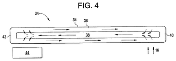
24 ヒートパイプ
26 SCRダクト
28 横列
30 縦列
32 アレイ
34 ケーシング
36 ウィック
38 蒸気空洞
40 高温端部
42 低温端部
44 ファン
46 固体媒体
Claims (10)
- それに沿って排気(16)を導きかつ放出する少なくとも1つの排気通路(18)と、
前記排気(16)から規制物質を除去することができる少なくとも1つの排気処理装置(22)と、
前記少なくとも1つの排気処理装置(22)の上流で少なくとも部分的に前記排気通路(18)内に配置された複数のヒートパイプ(24)と
を含むターボ機械であって、前記複数のヒートパイプ(24)が、前記排気(16)から該複数のヒートパイプ(24)に熱エネルギーを伝達させ、該排気(16)の温度を低下させて前記少なくとも1つの排気処理装置の有効性を高めることができる、ターボ機械(10)。 - 前記少なくとも1つの排気処理装置(22)が、少なくとも1つの選択触媒リアクタである、請求項1記載のターボ機械(10)。
- 前記複数のヒートパイプ(24)の少なくとも1つのヒートパイプが、蒸気空洞(38)内に配置された多量の流体と、前記蒸気空洞(38)内の流体を吸収することができるウィック(36)とを含んでいて、前記排気(16)の熱エネルギーが、前記ウィック(36)内の流体を前記蒸気空洞(38)に蒸発させることによって該ヒートパイプに伝達される、請求項1記載のターボ機械(10)。
- 前記複数のヒートパイプ(24)の少なくとも1つのヒートパイプが高熱伝導性固体媒体(46)を含んでいて、前記排気(16)の熱エネルギーが前記高熱伝導性固体媒体(46)を介して前記ヒートパイプに伝達される、請求項1記載のターボ機械(10)。
- 前記複数のヒートパイプ(24)が、前記排気(16)の温度を約800〜900°Fに低下させることができる、請求項1記載のターボ機械(10)。
- ターボ機械(10)排気(16)を放出する方法であって、
少なくとも1つの排気通路(18)に沿って前記排気(16)を流すステップと、
複数のヒートパイプ(24)を通過させて前記排気(16)を流すステップと、
前記排気(16)から前記複数のヒートパイプ(24)に熱エネルギーを伝達させ、従って該排気(16)の温度を低下させるステップと、
少なくとも1つの排気処理装置(22)を通して前記排気(16)を流すステップと、
前記少なくとも1つの排気処理装置(22)を介して前記排気(16)から規制物質を除去するステップと、
前記排気(16)を放免するステップと
を含む方法。 - 前記複数のヒートパイプ(24)の少なくとも1つのヒートパイプのウィック(36)内に含まれた液体を該複数のヒートパイプ(24)の少なくとも1つのヒートパイプの蒸気空洞(38)内に蒸発させることによって、前記排気(16)から熱エネルギーを伝達させるステップを含む、請求項6記載の方法。
- 前記少なくとも1つのヒートパイプの高温端部(40)から該少なくとも1つのヒートパイプの低温端部(42)に前記蒸発液体を流すステップを含む、請求項7記載の方法。
- 前記排気(16)から前記複数のヒートパイプ(24)の少なくとも1つのヒートパイプ内に配置された高熱伝導性固体媒体(46)に熱エネルギーを伝達するステップを含む、請求項6記載の方法。
- 前記排気(16)から前記複数のヒートパイプ(24)に熱エネルギーを伝達するステップが、該排気(16)の温度を約800〜900°Fに低下させる、請求項6記載の方法。
Applications Claiming Priority (2)
| Application Number | Priority Date | Filing Date | Title |
|---|---|---|---|
| US12/175,966 US8596073B2 (en) | 2008-07-18 | 2008-07-18 | Heat pipe for removing thermal energy from exhaust gas |
| US12/175,966 | 2008-07-18 |
Publications (2)
| Publication Number | Publication Date |
|---|---|
| JP2010025108A true JP2010025108A (ja) | 2010-02-04 |
| JP5903202B2 JP5903202B2 (ja) | 2016-04-13 |
Family
ID=40933794
Family Applications (1)
| Application Number | Title | Priority Date | Filing Date |
|---|---|---|---|
| JP2009166228A Expired - Fee Related JP5903202B2 (ja) | 2008-07-18 | 2009-07-15 | 排気ガスから熱エネルギーを除去するためのヒートパイプを備えるターボ機械並びに排気方法 |
Country Status (4)
| Country | Link |
|---|---|
| US (1) | US8596073B2 (ja) |
| EP (1) | EP2146075A3 (ja) |
| JP (1) | JP5903202B2 (ja) |
| CN (1) | CN101629516B (ja) |
Cited By (1)
| Publication number | Priority date | Publication date | Assignee | Title |
|---|---|---|---|---|
| US12454910B1 (en) | 2024-07-31 | 2025-10-28 | Ge Infrastructure Technology Llc | Combined cycle power plant with steam turbine bypass for simple cycle operation with heat recovery steam generator and method of use |
Families Citing this family (28)
| Publication number | Priority date | Publication date | Assignee | Title |
|---|---|---|---|---|
| US8516786B2 (en) * | 2009-08-13 | 2013-08-27 | General Electric Company | System and method for injection of cooling air into exhaust gas flow |
| US8973650B2 (en) * | 2010-07-20 | 2015-03-10 | General Electric Company | Superconductive heat transfer system |
| AT511051B1 (de) | 2011-01-27 | 2013-01-15 | Ge Jenbacher Gmbh & Co Ohg | Katalysatoranordnung für eine abgasreinigungsvorrichtung einer brennkraftmaschine |
| US8746975B2 (en) | 2011-02-17 | 2014-06-10 | Media Lario S.R.L. | Thermal management systems, assemblies and methods for grazing incidence collectors for EUV lithography |
| US8731139B2 (en) | 2011-05-04 | 2014-05-20 | Media Lario S.R.L. | Evaporative thermal management of grazing incidence collectors for EUV lithography |
| US9890672B2 (en) | 2012-09-06 | 2018-02-13 | Mitsubishi Hitachi Power Systems, Ltd. | Combustion gas cooling apparatus, denitration apparatus having the combustion gas cooling apparatus, and combustion gas cooling method |
| CN103195576B (zh) * | 2013-03-25 | 2015-05-20 | 哈尔滨工程大学 | 一种船舶燃气轮机排烟红外抑制装置 |
| US20150300261A1 (en) * | 2014-04-17 | 2015-10-22 | General Electric Company | Fuel heating system for use with a combined cycle gas turbine |
| JP6282184B2 (ja) | 2014-06-19 | 2018-02-21 | 三菱日立パワーシステムズ株式会社 | 伝熱装置及びそれを備えたガスタービン燃焼器 |
| CN104632461B (zh) * | 2015-02-04 | 2016-02-10 | 山东大学 | 一种换热量可控的汽车尾气换热器及其工作方法 |
| US9797310B2 (en) | 2015-04-02 | 2017-10-24 | General Electric Company | Heat pipe temperature management system for a turbomachine |
| JP6585073B2 (ja) | 2015-04-02 | 2019-10-02 | ゼネラル・エレクトリック・カンパニイ | ターボ機械におけるホイールおよびバケットのためのヒートパイプ温度管理システム |
| US20160290235A1 (en) * | 2015-04-02 | 2016-10-06 | General Electric Company | Heat pipe temperature management system for a turbomachine |
| US20160290214A1 (en) * | 2015-04-02 | 2016-10-06 | General Electric Company | Heat pipe cooled turbine casing system for clearance management |
| US9644512B2 (en) * | 2015-05-05 | 2017-05-09 | Cummins Emission Solutions, Inc. | Dosing module with integrated heat pipe |
| US10005016B2 (en) | 2015-12-28 | 2018-06-26 | General Electric Company | Hydrophobic filtration of tempering air |
| CN105626265B (zh) * | 2015-12-30 | 2017-04-19 | 中国航空工业集团公司沈阳发动机设计研究所 | 一种燃气轮机间冷回热系统 |
| US10450929B2 (en) | 2016-01-20 | 2019-10-22 | General Electric Company | Anti-icing system and method for gas turbine exhaust sections |
| US10092878B2 (en) | 2016-03-03 | 2018-10-09 | General Electric Company | System and method for mixing tempering air with flue gas for hot SCR catalyst |
| US10883387B2 (en) | 2016-03-07 | 2021-01-05 | General Electric Company | Gas turbine exhaust diffuser with air injection |
| US10385779B2 (en) | 2016-06-07 | 2019-08-20 | General Electric Company | System for cooling exhaust gas with absorption chiller |
| US20170356319A1 (en) * | 2016-06-09 | 2017-12-14 | General Electric Company | Exhaust Gas Heat Exchange for Ammonia Evaporation Using a Heat Pipe |
| CN105952519A (zh) * | 2016-07-16 | 2016-09-21 | 李陶胜 | 一种内燃机进排气系统净化装置 |
| US10309242B2 (en) * | 2016-08-10 | 2019-06-04 | General Electric Company | Ceramic matrix composite component cooling |
| US10450957B2 (en) * | 2017-01-23 | 2019-10-22 | United Technologies Corporation | Gas turbine engine with heat pipe system |
| KR102598538B1 (ko) * | 2018-10-22 | 2023-11-03 | 현대자동차주식회사 | 차량용 배기 테일 트림 |
| CN109989811A (zh) * | 2019-05-14 | 2019-07-09 | 河北工业大学 | 一种中间介质型内燃机尾气温差发电装置 |
| KR20220146652A (ko) * | 2020-03-06 | 2022-11-01 | 홀텍 인터내셔날 | 유도 통풍 공랭식 응축기 시스템 |
Citations (14)
| Publication number | Priority date | Publication date | Assignee | Title |
|---|---|---|---|---|
| JPS4893809A (ja) * | 1972-03-17 | 1973-12-04 | ||
| JPS492041U (ja) * | 1972-04-06 | 1974-01-09 | ||
| JPS56141039A (en) * | 1980-04-07 | 1981-11-04 | Nissan Motor Co Ltd | Recovering device of heat from exhaust gas |
| JPS6212717U (ja) * | 1985-07-08 | 1987-01-26 | ||
| JPH01119330A (ja) * | 1987-11-02 | 1989-05-11 | Ishikawajima Harima Heavy Ind Co Ltd | ガスタービン排ガスの脱硝方法 |
| JPH0193358U (ja) * | 1987-12-14 | 1989-06-20 | ||
| JPH06108877A (ja) * | 1992-09-25 | 1994-04-19 | Mitsubishi Heavy Ind Ltd | ガスタービン単独発電システム |
| JPH08293315A (ja) * | 1995-04-21 | 1996-11-05 | Toshiba Corp | 燃料電池発電装置用脱硫器 |
| JPH1193694A (ja) * | 1997-09-18 | 1999-04-06 | Toshiba Corp | ガスタービンプラント |
| US5918555A (en) * | 1996-04-19 | 1999-07-06 | Winegar; Phillip | Catalytic method for NOX reduction |
| JP2002501599A (ja) * | 1996-10-25 | 2002-01-15 | ク,ユズイ | 超伝導熱伝達媒質 |
| JP2002071090A (ja) * | 2000-08-31 | 2002-03-08 | Ishikawajima Harima Heavy Ind Co Ltd | 極小流量用の冷却器付きオイルタンク |
| JP2005069161A (ja) * | 2003-08-27 | 2005-03-17 | Toyota Motor Corp | 内燃機関の排気浄化処理装置 |
| JP2007064228A (ja) * | 2005-09-01 | 2007-03-15 | General Electric Co <Ge> | ガスタービンエンジンを動作させる装置 |
Family Cites Families (53)
| Publication number | Priority date | Publication date | Assignee | Title |
|---|---|---|---|---|
| DE294483C (ja) | ||||
| US3517730A (en) * | 1967-03-15 | 1970-06-30 | Us Navy | Controllable heat pipe |
| US3722797A (en) * | 1970-11-04 | 1973-03-27 | Cci Aerospace Corp | Convergent divergent ejector exhaust nozzle |
| US4036290A (en) * | 1972-01-24 | 1977-07-19 | Kelly Donald A | Helical expansion condenser |
| US3852805A (en) * | 1973-06-18 | 1974-12-03 | Gen Electric | Heat-pipe cooled power semiconductor device assembly having integral semiconductor device evaporating surface unit |
| GB1446750A (en) * | 1973-12-20 | 1976-08-18 | Plessey Co Ltd | Engines having heat re-cycling means |
| US4033406A (en) * | 1974-09-03 | 1977-07-05 | Hughes Aircraft Company | Heat exchanger utilizing heat pipes |
| US4372110A (en) * | 1976-02-13 | 1983-02-08 | Nasa | Noise suppressor for turbo fan jet engines |
| US4149588A (en) * | 1976-03-15 | 1979-04-17 | Mcdonnell Douglas Corporation | Dry cooling system |
| US4621681A (en) * | 1977-11-09 | 1986-11-11 | Q-Dot Corporation | Waste heat boiler |
| US4234782A (en) * | 1978-01-19 | 1980-11-18 | Saskatchewan Power Corporation | Space heating using off-peak electric heat storage |
| US4226282A (en) * | 1978-08-30 | 1980-10-07 | Foster Wheeler Energy Corporation | Heat exchange apparatus utilizing thermal siphon pipes |
| US4280554A (en) * | 1980-02-04 | 1981-07-28 | The Air Preheater Company, Inc. | Heat tube |
| US4567857A (en) * | 1980-02-26 | 1986-02-04 | The United States Of America As Represented By The Administrator Of The National Aeronautics And Space Administration | Combustion engine system |
| US4426959A (en) * | 1980-07-01 | 1984-01-24 | Q-Dot Corporation | Waste heat recovery system having thermal sleeve support for heat pipe |
| US6866092B1 (en) * | 1981-02-19 | 2005-03-15 | Stephen Molivadas | Two-phase heat-transfer systems |
| US4381817A (en) | 1981-04-27 | 1983-05-03 | Foster Wheeler Energy Corporation | Wet/dry steam condenser |
| US4570466A (en) * | 1983-09-09 | 1986-02-18 | Laser Products Corporation | Door locking methods and apparatus |
| US4932204A (en) * | 1989-04-03 | 1990-06-12 | Westinghouse Electric Corp. | Efficiency combined cycle power plant |
| CN2110932U (zh) | 1992-01-18 | 1992-07-22 | 李宗祥 | 吸热式冷却装置 |
| US5248252A (en) * | 1992-06-30 | 1993-09-28 | Gas Research Institute | Enhanced radiant output burner |
| US5233934A (en) * | 1992-08-20 | 1993-08-10 | Wahlco Environmental Systems, Inc. | Control of NOx reduction in flue gas flows |
| US5237939A (en) * | 1992-08-20 | 1993-08-24 | Wahlco Environmental Systems, Inc. | Method and apparatus for reducing NOx emissions |
| US5311930A (en) * | 1992-11-17 | 1994-05-17 | Bruenn Paul R | Heat reclamation device |
| US5632143A (en) * | 1994-06-14 | 1997-05-27 | Ormat Industries Ltd. | Gas turbine system and method using temperature control of the exhaust gas entering the heat recovery cycle by mixing with ambient air |
| DE19512466C1 (de) * | 1995-04-03 | 1996-08-22 | Siemens Ag | Verfahren zum Betreiben eines Abhitzedampferzeugers sowie danach arbeitender Abhitzedampferzeuger |
| EP0794401A3 (en) | 1996-03-06 | 1998-09-23 | Hudson Products Corporation | Steam condensing apparatus |
| US6916430B1 (en) * | 1996-10-25 | 2005-07-12 | New Qu Energy Ltd. | Superconducting heat transfer medium |
| US5845481A (en) * | 1997-01-24 | 1998-12-08 | Westinghouse Electric Corporation | Combustion turbine with fuel heating system |
| US6065280A (en) * | 1998-04-08 | 2000-05-23 | General Electric Co. | Method of heating gas turbine fuel in a combined cycle power plant using multi-component flow mixtures |
| US6241009B1 (en) * | 2000-02-07 | 2001-06-05 | Hudson Products Corporation | Integrated heat pipe vent condenser |
| US6397575B2 (en) * | 2000-03-23 | 2002-06-04 | General Electric Company | Apparatus and methods of reheating gas turbine cooling steam and high pressure steam turbine exhaust in a combined cycle power generating system |
| EP1193373A1 (de) * | 2000-09-29 | 2002-04-03 | Siemens Aktiengesellschaft | Verfahren zum Betreiben einer Gas- und Dampfturbinenanlage sowie entsprechende Anlage |
| US20030182944A1 (en) * | 2002-04-02 | 2003-10-02 | Hoffman John S. | Highly supercharged gas-turbine generating system |
| US7069716B1 (en) * | 2002-04-24 | 2006-07-04 | Express Integrated Technologies Llc | Cooling air distribution apparatus |
| US6782703B2 (en) * | 2002-09-11 | 2004-08-31 | Siemens Westinghouse Power Corporation | Apparatus for starting a combined cycle power plant |
| US6962051B2 (en) * | 2003-06-17 | 2005-11-08 | Utc Power, Llc | Control of flow through a vapor generator |
| US7131294B2 (en) * | 2004-01-13 | 2006-11-07 | Tecumseh Products Company | Method and apparatus for control of carbon dioxide gas cooler pressure by use of a capillary tube |
| GB2414690A (en) * | 2004-06-04 | 2005-12-07 | Ford Global Tech Llc | An emission control apparatus for an engine |
| JP2006090156A (ja) * | 2004-09-21 | 2006-04-06 | Shin Caterpillar Mitsubishi Ltd | 廃熱エネルギ再生方法および廃熱エネルギ再生装置 |
| US20060083626A1 (en) * | 2004-10-19 | 2006-04-20 | Manole Dan M | Compressor and hermetic housing with minimal housing ports |
| JP2006284144A (ja) * | 2005-04-04 | 2006-10-19 | Denso Corp | 排熱回収装置 |
| JP2006317013A (ja) * | 2005-04-12 | 2006-11-24 | Denso Corp | ヒートパイプおよびそれを用いた排熱回収装置 |
| US20070017207A1 (en) * | 2005-07-25 | 2007-01-25 | General Electric Company | Combined Cycle Power Plant |
| US7730727B2 (en) * | 2005-09-06 | 2010-06-08 | American Air Liquide, Inc. | Flexible flow control device for cogeneration ducting applications |
| US7523602B2 (en) * | 2005-09-27 | 2009-04-28 | United Technologies Corporation | Turbine exhaust catalyst |
| EP1801241A1 (en) * | 2005-12-23 | 2007-06-27 | Paul Wurth S.A. | A rotary charging device for a shaft furnace equipped with a cooling system |
| US7382047B2 (en) * | 2005-12-27 | 2008-06-03 | Fu Zhun Precision Industry (Shen Zhen) Co., Ltd. | Heat dissipation device |
| US7621720B2 (en) * | 2006-06-30 | 2009-11-24 | General Electric Company | Cooling device |
| US7584748B2 (en) | 2006-11-20 | 2009-09-08 | Gm Global Technology Operations, Inc. | Exhaust gas recirculation system for an internal combustion engine |
| US7784300B2 (en) * | 2006-12-22 | 2010-08-31 | Yiding Cao | Refrigerator |
| US20080164009A1 (en) * | 2007-01-07 | 2008-07-10 | Yong Chong | Direct Embedded Heat Pipe Apparatus |
| US8359824B2 (en) * | 2008-07-29 | 2013-01-29 | General Electric Company | Heat recovery steam generator for a combined cycle power plant |
-
2008
- 2008-07-18 US US12/175,966 patent/US8596073B2/en not_active Expired - Fee Related
-
2009
- 2009-07-13 EP EP09165356.8A patent/EP2146075A3/en not_active Withdrawn
- 2009-07-15 JP JP2009166228A patent/JP5903202B2/ja not_active Expired - Fee Related
- 2009-07-16 CN CN200910161615.1A patent/CN101629516B/zh not_active Expired - Fee Related
Patent Citations (14)
| Publication number | Priority date | Publication date | Assignee | Title |
|---|---|---|---|---|
| JPS4893809A (ja) * | 1972-03-17 | 1973-12-04 | ||
| JPS492041U (ja) * | 1972-04-06 | 1974-01-09 | ||
| JPS56141039A (en) * | 1980-04-07 | 1981-11-04 | Nissan Motor Co Ltd | Recovering device of heat from exhaust gas |
| JPS6212717U (ja) * | 1985-07-08 | 1987-01-26 | ||
| JPH01119330A (ja) * | 1987-11-02 | 1989-05-11 | Ishikawajima Harima Heavy Ind Co Ltd | ガスタービン排ガスの脱硝方法 |
| JPH0193358U (ja) * | 1987-12-14 | 1989-06-20 | ||
| JPH06108877A (ja) * | 1992-09-25 | 1994-04-19 | Mitsubishi Heavy Ind Ltd | ガスタービン単独発電システム |
| JPH08293315A (ja) * | 1995-04-21 | 1996-11-05 | Toshiba Corp | 燃料電池発電装置用脱硫器 |
| US5918555A (en) * | 1996-04-19 | 1999-07-06 | Winegar; Phillip | Catalytic method for NOX reduction |
| JP2002501599A (ja) * | 1996-10-25 | 2002-01-15 | ク,ユズイ | 超伝導熱伝達媒質 |
| JPH1193694A (ja) * | 1997-09-18 | 1999-04-06 | Toshiba Corp | ガスタービンプラント |
| JP2002071090A (ja) * | 2000-08-31 | 2002-03-08 | Ishikawajima Harima Heavy Ind Co Ltd | 極小流量用の冷却器付きオイルタンク |
| JP2005069161A (ja) * | 2003-08-27 | 2005-03-17 | Toyota Motor Corp | 内燃機関の排気浄化処理装置 |
| JP2007064228A (ja) * | 2005-09-01 | 2007-03-15 | General Electric Co <Ge> | ガスタービンエンジンを動作させる装置 |
Cited By (1)
| Publication number | Priority date | Publication date | Assignee | Title |
|---|---|---|---|---|
| US12454910B1 (en) | 2024-07-31 | 2025-10-28 | Ge Infrastructure Technology Llc | Combined cycle power plant with steam turbine bypass for simple cycle operation with heat recovery steam generator and method of use |
Also Published As
| Publication number | Publication date |
|---|---|
| US8596073B2 (en) | 2013-12-03 |
| US20100011738A1 (en) | 2010-01-21 |
| JP5903202B2 (ja) | 2016-04-13 |
| CN101629516A (zh) | 2010-01-20 |
| EP2146075A3 (en) | 2017-05-17 |
| EP2146075A2 (en) | 2010-01-20 |
| CN101629516B (zh) | 2015-10-07 |
Similar Documents
| Publication | Publication Date | Title |
|---|---|---|
| JP5903202B2 (ja) | 排気ガスから熱エネルギーを除去するためのヒートパイプを備えるターボ機械並びに排気方法 | |
| US8112998B2 (en) | Apparatus and method for cooling a turbine using heat pipes | |
| JP2010025107A (ja) | ターボ機械排気を冷却するための装置及び方法 | |
| JP5752367B2 (ja) | 排気ガス流中に冷却空気を噴射するためのシステム及び方法 | |
| US7748211B2 (en) | Vapor cooling of detonation engines | |
| EP3214278B1 (en) | System and method for mixing tempering air with flue gas for hot scr catalyst | |
| US20100263388A1 (en) | Vapor cooled static turbine hardware | |
| JP2007182874A (ja) | アクティブクリアランス制御のためのガスタービンエンジンリングの熱制御 | |
| TW201035494A (en) | Heat exchanger | |
| WO2018017737A1 (en) | Systems and methods for cooling components within a gas turbine engine | |
| JP2007162698A (ja) | ガスタービンエンジンアクティブクリアランス制御の使用済み冷却空気を排気するシステムおよび方法 | |
| US20140026751A1 (en) | System and method for capturing carbon dioxide from flue gas | |
| US20170350320A1 (en) | System for Cooling Exhaust Gas with Absorption Chiller | |
| US20170356319A1 (en) | Exhaust Gas Heat Exchange for Ammonia Evaporation Using a Heat Pipe | |
| KR20170087419A (ko) | 가스 터빈용 결빙-방지 시스템 | |
| JP6417167B2 (ja) | ガスタービン | |
| JP7091312B2 (ja) | ガスタービン選択的触媒還元システムのためのアンモニア注入調節 | |
| JP5099967B2 (ja) | ガスタービンエンジンを作動させるための方法及び装置 | |
| CN104204461B (zh) | 用于运行燃气轮机的方法和用于实施该方法的燃气轮机 | |
| JP2010048546A (ja) | ディンプル及びセレーション成形フィン付きチューブ構造 | |
| JP2013160406A (ja) | 潜熱回収型燃焼機器における排気の結露防止装置 | |
| US7954324B2 (en) | Gas turbine engine | |
| JP6929370B2 (ja) | 希釈選択的触媒還元システムを備える、化石燃料を動力源とするエンジンのための排気ダクト | |
| US20110262265A1 (en) | Installation having a thermal transfer arrangement | |
| JP5448938B2 (ja) | ガスタービンの吸気システムおよびこれを備えたガスタービン |
Legal Events
| Date | Code | Title | Description |
|---|---|---|---|
| A621 | Written request for application examination |
Free format text: JAPANESE INTERMEDIATE CODE: A621 Effective date: 20120711 |
|
| A131 | Notification of reasons for refusal |
Free format text: JAPANESE INTERMEDIATE CODE: A131 Effective date: 20130625 |
|
| A977 | Report on retrieval |
Free format text: JAPANESE INTERMEDIATE CODE: A971007 Effective date: 20130628 |
|
| A601 | Written request for extension of time |
Free format text: JAPANESE INTERMEDIATE CODE: A601 Effective date: 20130925 |
|
| A602 | Written permission of extension of time |
Free format text: JAPANESE INTERMEDIATE CODE: A602 Effective date: 20130930 |
|
| A601 | Written request for extension of time |
Free format text: JAPANESE INTERMEDIATE CODE: A601 Effective date: 20131024 |
|
| A602 | Written permission of extension of time |
Free format text: JAPANESE INTERMEDIATE CODE: A602 Effective date: 20131029 |
|
| A601 | Written request for extension of time |
Free format text: JAPANESE INTERMEDIATE CODE: A601 Effective date: 20131122 |
|
| A602 | Written permission of extension of time |
Free format text: JAPANESE INTERMEDIATE CODE: A602 Effective date: 20131127 |
|
| A521 | Written amendment |
Free format text: JAPANESE INTERMEDIATE CODE: A523 Effective date: 20131224 |
|
| A131 | Notification of reasons for refusal |
Free format text: JAPANESE INTERMEDIATE CODE: A131 Effective date: 20140603 |
|
| A601 | Written request for extension of time |
Free format text: JAPANESE INTERMEDIATE CODE: A601 Effective date: 20140902 |
|
| A602 | Written permission of extension of time |
Free format text: JAPANESE INTERMEDIATE CODE: A602 Effective date: 20140905 |
|
| A601 | Written request for extension of time |
Free format text: JAPANESE INTERMEDIATE CODE: A601 Effective date: 20141002 |
|
| A602 | Written permission of extension of time |
Free format text: JAPANESE INTERMEDIATE CODE: A602 Effective date: 20141007 |
|
| A601 | Written request for extension of time |
Free format text: JAPANESE INTERMEDIATE CODE: A601 Effective date: 20141031 |
|
| A602 | Written permission of extension of time |
Free format text: JAPANESE INTERMEDIATE CODE: A602 Effective date: 20141106 |
|
| A02 | Decision of refusal |
Free format text: JAPANESE INTERMEDIATE CODE: A02 Effective date: 20150707 |
|
| A521 | Written amendment |
Free format text: JAPANESE INTERMEDIATE CODE: A523 Effective date: 20151106 |
|
| A911 | Transfer of reconsideration by examiner before appeal (zenchi) |
Free format text: JAPANESE INTERMEDIATE CODE: A911 Effective date: 20151222 |
|
| A131 | Notification of reasons for refusal |
Free format text: JAPANESE INTERMEDIATE CODE: A131 Effective date: 20160126 |
|
| A521 | Written amendment |
Free format text: JAPANESE INTERMEDIATE CODE: A523 Effective date: 20160128 |
|
| TRDD | Decision of grant or rejection written | ||
| A01 | Written decision to grant a patent or to grant a registration (utility model) |
Free format text: JAPANESE INTERMEDIATE CODE: A01 Effective date: 20160216 |
|
| A61 | First payment of annual fees (during grant procedure) |
Free format text: JAPANESE INTERMEDIATE CODE: A61 Effective date: 20160314 |
|
| R150 | Certificate of patent or registration of utility model |
Ref document number: 5903202 Country of ref document: JP Free format text: JAPANESE INTERMEDIATE CODE: R150 |
|
| LAPS | Cancellation because of no payment of annual fees |